EP1506909A1 - Heckflügel für ein Kraftfahrzeug - Google Patents
Heckflügel für ein Kraftfahrzeug Download PDFInfo
- Publication number
- EP1506909A1 EP1506909A1 EP04014417A EP04014417A EP1506909A1 EP 1506909 A1 EP1506909 A1 EP 1506909A1 EP 04014417 A EP04014417 A EP 04014417A EP 04014417 A EP04014417 A EP 04014417A EP 1506909 A1 EP1506909 A1 EP 1506909A1
- Authority
- EP
- European Patent Office
- Prior art keywords
- rear wing
- web
- wing according
- transverse
- hollow body
- Prior art date
- Legal status (The legal status is an assumption and is not a legal conclusion. Google has not performed a legal analysis and makes no representation as to the accuracy of the status listed.)
- Granted
Links
Images


Classifications
-
- B—PERFORMING OPERATIONS; TRANSPORTING
- B62—LAND VEHICLES FOR TRAVELLING OTHERWISE THAN ON RAILS
- B62D—MOTOR VEHICLES; TRAILERS
- B62D35/00—Vehicle bodies characterised by streamlining
- B62D35/007—Rear spoilers
-
- Y—GENERAL TAGGING OF NEW TECHNOLOGICAL DEVELOPMENTS; GENERAL TAGGING OF CROSS-SECTIONAL TECHNOLOGIES SPANNING OVER SEVERAL SECTIONS OF THE IPC; TECHNICAL SUBJECTS COVERED BY FORMER USPC CROSS-REFERENCE ART COLLECTIONS [XRACs] AND DIGESTS
- Y02—TECHNOLOGIES OR APPLICATIONS FOR MITIGATION OR ADAPTATION AGAINST CLIMATE CHANGE
- Y02T—CLIMATE CHANGE MITIGATION TECHNOLOGIES RELATED TO TRANSPORTATION
- Y02T10/00—Road transport of goods or passengers
- Y02T10/80—Technologies aiming to reduce greenhouse gasses emissions common to all road transportation technologies
- Y02T10/82—Elements for improving aerodynamics
-
- Y—GENERAL TAGGING OF NEW TECHNOLOGICAL DEVELOPMENTS; GENERAL TAGGING OF CROSS-SECTIONAL TECHNOLOGIES SPANNING OVER SEVERAL SECTIONS OF THE IPC; TECHNICAL SUBJECTS COVERED BY FORMER USPC CROSS-REFERENCE ART COLLECTIONS [XRACs] AND DIGESTS
- Y10—TECHNICAL SUBJECTS COVERED BY FORMER USPC
- Y10S—TECHNICAL SUBJECTS COVERED BY FORMER USPC CROSS-REFERENCE ART COLLECTIONS [XRACs] AND DIGESTS
- Y10S180/00—Motor vehicles
- Y10S180/903—Airstream reactive vehicle or vehicle structure
Definitions
- a generic rear wing can be found in DE 100 02 511 A1. He is as Hollow body realized, the two - part of an upper and a lower part composed of a wing roof and a wing bottom. A front Section of the joining surface between the upper and lower part lies - seen in the direction of travel - on a front end of the rear wing. By a screw connection Upper and lower parts attached to each other.
- the rear wing also has an inside the hollow body arranged reinforcing structure, the one in the vehicle transverse direction extending transverse web, of which V - shaped aligned on both web surfaces Inclined webs and extending approximately in the vehicle longitudinal direction, between the Oblique webs lying longitudinal webs go out. At both lateral ends of the Hollow body are in the wing bottom each with a lateral distance to Reinforcement structure breakthroughs introduced, through each of which a coupling rod passes, the operation of a disposed within the hollow body Serve flap.
- the object of the invention is to provide a rear wing of the generic type, at the possibly penetrating into the hollow body water can be discharged again.
- Fig. 1 and 2 show a schematically illustrated in side view motor vehicle 1, in particular passenger cars, a rear end 2, at the top 3 a Aerodynamically effective and / or optical effect unfolding air guiding device 4th is arranged, the at least one the outer skin 5 of the body 6 of the motor vehicle superior rear wing 7 has.
- the louver 4 is as So-called split wing executed and therefore includes next to the rear wing 7 yet a below the rear wing 7 lying, fixed rear spoiler 8.
- the rear wing 7 from a retracted position shown in Fig. 1 RS in a in Fig. 2 illustrated operating position BS extendable, whereby between the rear wing 7 and fixed rear spoiler a gap 9 is formed.
- the Rear wing 7 Compared to the body 6 is the Rear wing 7, for example, two supports, of which only a support 10th is shown, supported, which - if the rear wing 7 is extendable - an exhibitor record (not shown).
- the rear wing 7 could in another embodiment in the position shown in Fig. 2 stationary and immovable with the body be connected.
- the rear wing 7 is described in more detail, as the hollow body 11th is executed, the upper wing roof 12 and a lower wing bottom 13th and further includes an inner reinforcing structure 14.
- the hollow body 11 is at least made in two parts and the parts 15 and 16 are the hollow body eleventh put together and lie in a circumferential joining surface 17 to each other, which Joining surface 17 at least one - seen in the direction of travel FR - front portion 18th has, which is located on a front end face 19 of the rear wing 7.
- Part 15 is as Lower shell 20 and the part 16 realized as an upper shell 21 of the hollow body 11, wherein the lower shell 20 the wing bottom 13 and possibly at least partially the end wall 19th and the upper shell 21, the wing roof 12 and possibly a rear wall 19 'has and each extend into the joint surface 17.
- the parts 15 and 16 are through a detent or clip connection, not shown attached to each other and in the Joining surface 17 push the parts 15 and 16 together if necessary unconnected.
- the detent or clip connection within the hollow body and adjacent to Joining surface 17 distributed distributed in several places.
- the reinforcing structure 14 has a plurality of upright, in the hollow body eleventh protruding webs, of which at least one in the vehicle transverse direction FQ extending transverse web 22 and other webs as extending in the vehicle longitudinal direction FL Longitudinal webs 23 are oriented.
- Another crosspiece 24 is - in the direction FR - seen - arranged at a distance behind the front crossbar 22. Between the two Transverse webs 22 and 24 extend the longitudinal webs 23, so that the section 18 facing web surface 25 of the front transverse web 22 without a seam, ie flat or smooth surface formed and otherwise the portion 18 of the joint surface 17 faces is.
- the longitudinal webs 23 thus extend between the flat web surface 25th remote from the back 25 'of the crosspiece 22 and the other lying behind Crosspiece 24, at the back 25 ", the longitudinal webs 23 may be continued.
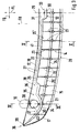
- At least the front transverse web 22 of the reinforcing structure 14 is connected to the inner surface 26 of the wing bottom 13 tightly connected and the transverse web 22 and the inner surface 26th Form walls 27 of a water channel 28, which extends in the vehicle transverse direction FQ may substantially extend the width of the rear wing 7.
- the inner surface 26 is preferably counter to the direction of travel FR inclined or falls in the direction of the web surface 25 and thus includes an angle with a horizontal, not shown, so that the water channel 28 may have an approximately V-shaped cross-section.
- Fig. 3 only one half of the rear wing 7 is shown, thus with respect to a in the vehicle longitudinal direction FL extending mirror axis 29 is symmetrical.
- the water channel 28 is at least one opening 30, the wing bottom 13th completely penetrated and so forms a water drainage opening.
- About - in Vehicle transverse direction FQ seen - center of the rear wing 7 is the crossbar 22nd counter to the direction of travel FR in a first region 31 via a step 32 set back so that a first basin-like collecting portion 33 of the water channel 28 is executed, in which the opening 30, preferably adjacent to the web surface 25, lies.
- the transverse web 22 is set back counter to the direction of travel FR, so that a second basin-like collecting portion 35 of the water channel 28 at the lateral end 36 of the Rear wing 7 is arranged, which collecting portion 35 a step 32 and a subsequent recessed collection sheet 37 has.
- the collection sheet 37 is a - seen in the direction of travel FR - in front of him ring collar 38th guided around and sets the crossbar 22 to the front portion 18 of the joint surface 17 away, so that a web end 39 adjacent to the section 18 is or thereto zoom ranges.
- the annular collar 38 forms a lying within the rear wing 7 Extension of the otherwise outside of the hollow body 11 support 10, which already mentioned, but not shown exhibitor for the rear wing 7 in its interior 40th can record.
- the annular collar 38 extends from the inner surface 26 of the lower shell 20th and prevents water from entering the interior 40 of the support 10 can.
- In one or both collection sections 33 and 35 is at least one breakthrough 30 arranged.
- the lower shell 20 with the reinforcing structure 14 and possibly with the Support 10 may be manufactured as a one-piece component, in particular made of plastic.
- a Wasserabweissteg 42 From the section through the rear wing 7 of FIG. 5 is at the part 16 and at the Upper shell 21 is still a Wasserab Stammsteg 42 can be seen that the flat web surface 25th - Seen in the direction of travel FR - upstream, ie between the section 18 of Joining surface 17 and the cross bar 22 is arranged upright.
- the Wasserabweissteg 42 runs along the transverse web 22 and possibly at least in sections parallel to Section 18 of the joining surface 17 and / or the transverse web 22; he extends preferably up to the web end 39 and starts from the wing roof bottom 43 and points in the direction of the wing bottom 13.
- the Wasserabweissteg 42 - Direction seen FR - lie at a distance to the cross bar 22 or even at it be created.
- the height of possibly integral with the - for example, plastic manufactured - upper shell 21 realized Wasserabweisstegs 42 is preferably so dimensioned that its free end 44 protrudes into the water channel 28, so with his End 44 is below the free end 45 of the crosspiece 22, but at a distance from Inner surface 26 completes.
- the Wasserab Stammg 42 thus forms a barrier for on Section 18, if necessary, penetrating water from the Wasserabweissteg 42 in the Water channel 28 drips off.
- Wasserabweissteg 42 and cross bar 22 thus form a labyrinthine seal, which is a penetration of the water to behind the crossbar 22nd prevented, but at least diminished.
Landscapes
- Engineering & Computer Science (AREA)
- Chemical & Material Sciences (AREA)
- Combustion & Propulsion (AREA)
- Transportation (AREA)
- Mechanical Engineering (AREA)
- Body Structure For Vehicles (AREA)
Abstract
Description
- Fig. 1
- ausschnittweise ein Kraftfahrzeug mit einer an einer Heckpartie angeordneten Luftleiteinrichtung mit einem Heckflügel in Ruhestellung,
- Fig. 2
- die Luftleiteinrichtung nach Fig. 1 mit dem in Betriebsstellung ausgefahrenen Heckflügel,
- Fig. 3
- eine Schnittdarstellung des Heckflügels entlang der Schnittlinie III - III in Fig. 2,
- Fig. 4
- eine Schnittdarstellung des Heckflügels entlang der Schnittlinie IV - IV in Fig. 3 und
- Fig. 5
- eine Schnittdarstellung des Heckflügels entlang der Schnittlinie V - V in Fig. 3.
Claims (19)
- Heckflügel für ein Kraftfahrzeug, mit einem Hohlkörper, der aus wenigstens zwei Teilen zusammengefügt ist, mit einem Flügeldach und einem Flügelboden, mit einer innerhalb des Hohlkörpers angeordneten, mehrere aufrechte Stege aufweisenden Verstärkungsstruktur, von der wenigstens ein in Fahrzeugquerrichtung verlaufender Quersteg mit der Innenfläche des Flügelbodens verbunden ist, und mit zumindest einem in dem Flügelboden eingebrachten Durchbruch, dadurch gekennzeichnet, dass der wenigstens eine Quersteg (22) eine ebene Stegfläche (25) aufweist, die eine Wandung (27) eines Wasserkanals (28) bildet, und dass im Verlauf des Wasserkanals (28) der zumindest eine Durchbruch (30) liegt.
- Heckflügel nach Anspruch 1, dadurch gekennzeichnet, dass die Stegfläche (25) zusammen mit der Innenfläche (26) des Flügelbodens (13) den Wasserkanal (28) bildet.
- Heckflügel nach Anspruch 1, dadurch gekennzeichnet, dass ein Teil (15) des Hohlkörpers (11) eine Unterschale (20) und der andere Teil (16) eine Oberschale (21) bildet.
- Heckflügel nach Anspruch 1, dadurch gekennzeichnet, dass ein vorderer Abschnitt (18) der Fügefläche (17) der beiden Teile (15, 16) an einer - in Fahrtrichtung (FR) gesehen - vorderen Stirnseite (19) des Heckflügels (7) liegt.
- Heckflügel nach Anspruch 4, dadurch gekennzeichnet, dass die ebene Stegfläche (25) dem vorderen Abschnitt (18) der Fügefläche (17) zugewandt ist.
- Heckflügel nach Anspruch 1, dadurch gekennzeichnet, dass auf der Innenfläche (26) ein aufrechter Ringkragen (38) angeordnet ist, der einer Stütze (10) für den Heckflügel (7) zugeordnet ist.
- Heckflügel nach Anspruch 1, dadurch gekennzeichnet, dass der Quersteg (22) in zumindest einem Bereich (31, 34) - in Fahrrichtung (FR) gesehen - zurückversetzt ist und so zumindest einen Sammelabschnitt (33, 35) des Wasserkanals (28) bildet.
- Heckflügel nach Anspruch 7, dadurch gekennzeichnet, dass ein erster Sammelabschnitt (33) - in Fahrzeugquerrichtung (FQ) gesehen - etwa in der Mitte des Heckflügels (7) liegt.
- Heckflügel nach Anspruch 6 und 7, dadurch gekennzeichnet, dass ein zweiter Sammelabschnitt (35) - in Fahrtrichtung (FR) gesehen - um den Ringkragen (38), vorzugsweise in einem Sammelbogen (37), herumgeführt ist.
- Heckflügel nach Anspruch 7, dadurch gekennzeichnet, dass in dem zumindest einen Sammelabschnitt (33, 35) der zumindest eine Durchbruch (30) liegt.
- Heckflügel nach Anspruch 4, dadurch gekennzeichnet, dass ein Stegende (39) des Querstegs (22) benachbart zum vorderen Abschnitt (18) der Fügefläche (17) liegt.
- Heckflügel nach Anspruch 9, dadurch gekennzeichnet, dass der zurückversetzte zweite Sammelabschnitt (35) bis zu dem Stegende (39) des Querstegs (22) fortgesetzt ist.
- Heckflügel nach Anspruch 7, dadurch gekennzeichnet, dass ein Stegabschnitt (41) des Querstegs (22) in Richtung des zumindest einen Sammelabschnitts (33, 35) abfallend ausgeführt ist.
- Heckflügel nach Anspruch 13, dadurch gekennzeichnet, dass der Stegabschnitt (41) in Richtung des ersten Sammelabschnitts (33) abfällt.
- Heckflügel nach Anspruch 13 oder 14, dadurch gekennzeichnet, dass zwischen dem Stegabschnitt (41) und dem zurückversetzten ersten Sammelabschnitt (33) eine Stufe (32) liegt.
- Heckflügel nach Anspruch 1, dadurch gekennzeichnet, dass die Verstärkungsstruktur (14) mehrere Längsstege (23) aufweist, die an einer der ebenen Stegfläche (25) abgewandten Rückseite (25') des Querstegs (22) liegen.
- Heckflügel nach Anspruch 1, dadurch gekennzeichnet, dass von der Unterseite (43) des Flügeldachs (13) ein Wasserabweissteg (42) ausgeht, der dem Quersteg (22) - in Fahrtrichtung (FR) gesehen - vorgelagert ist.
- Heckflügel nach Anspruch 17, dadurch gekennzeichnet, dass der Wasserabweissteg (42) in den Wasserkanal (28) hineinragt.
- Heckflügel nach Anspruch 17, dadurch gekennzeichnet, dass der Wasserabweissteg (42) entlang des Querstegs (22) verläuft.
Applications Claiming Priority (2)
| Application Number | Priority Date | Filing Date | Title |
|---|---|---|---|
| DE10336664A DE10336664A1 (de) | 2003-08-09 | 2003-08-09 | Heckflügel für ein Kraftfahrzeug |
| DE10336664 | 2003-08-09 |
Publications (2)
| Publication Number | Publication Date |
|---|---|
| EP1506909A1 true EP1506909A1 (de) | 2005-02-16 |
| EP1506909B1 EP1506909B1 (de) | 2006-11-02 |
Family
ID=33560282
Family Applications (1)
| Application Number | Title | Priority Date | Filing Date |
|---|---|---|---|
| EP04014417A Expired - Lifetime EP1506909B1 (de) | 2003-08-09 | 2004-06-19 | Heckflügel für ein Kraftfahrzeug |
Country Status (4)
| Country | Link |
|---|---|
| US (1) | US7036871B2 (de) |
| EP (1) | EP1506909B1 (de) |
| JP (1) | JP3954600B2 (de) |
| DE (2) | DE10336664A1 (de) |
Cited By (4)
| Publication number | Priority date | Publication date | Assignee | Title |
|---|---|---|---|---|
| CN105691474A (zh) * | 2014-12-12 | 2016-06-22 | 保时捷股份公司 | 下罩盖、用于生产下罩盖的成套部件及下罩盖的生产方法 |
| CN105691475A (zh) * | 2014-12-12 | 2016-06-22 | 保时捷股份公司 | 下罩盖、用于生产下罩盖的成套部件及下罩盖的生产方法 |
| CN107336757A (zh) * | 2017-06-25 | 2017-11-10 | 安徽机电职业技术学院 | 一种汽车尾翼安装板 |
| US20220281535A1 (en) * | 2021-03-04 | 2022-09-08 | Dr. Ing. H.C. F. Porsche Aktiengesellschaft | Rear spoiler arrangement |
Families Citing this family (19)
| Publication number | Priority date | Publication date | Assignee | Title |
|---|---|---|---|---|
| DE102004004360B4 (de) * | 2004-01-29 | 2007-01-25 | Dr.Ing.H.C. F. Porsche Ag | Kraftfahrzeug mit einer Luftleiteinrichtung |
| DE102004043544B4 (de) * | 2004-09-09 | 2007-09-06 | Audi Ag | Spoiler |
| US7654544B2 (en) * | 2005-11-02 | 2010-02-02 | Chrysler Group Llc | Air deflector arrangement for a vehicle |
| USD606917S1 (en) * | 2007-04-12 | 2009-12-29 | Dr. Ing. H.C. F. Porsche Aktiengesellschaft | Spoiler for an automobile |
| USD606918S1 (en) * | 2007-04-12 | 2009-12-29 | Dr. Ing. H.C. F. Porsche Aktiengesellschaft | Spoiler for an automobile |
| DE102010004560B4 (de) * | 2010-01-14 | 2024-09-12 | Dr. Ing. H.C. F. Porsche Aktiengesellschaft | Personenkraftfahrzeug mit heckseitiger Luftleitvorrichtung |
| DE102010004561A1 (de) * | 2010-01-14 | 2011-07-21 | Dr. Ing. h.c. F. Porsche Aktiengesellschaft, 70435 | Personenkraftfahrzeug mit heckseitiger Luftleitvorrichtung |
| JP5603182B2 (ja) * | 2010-09-14 | 2014-10-08 | 株式会社イノアックコーポレーション | スポイラ |
| DE102015102741A1 (de) * | 2015-02-26 | 2016-09-01 | Dr. Ing. H.C. F. Porsche Aktiengesellschaft | Luftleitvorrichtung und Verfahren zum Betreiben derselben |
| US9944335B2 (en) * | 2016-04-13 | 2018-04-17 | Fca Us Llc | Single form multi-airfoil element rear aerodynamic wing |
| KR101836736B1 (ko) * | 2016-11-14 | 2018-03-09 | 현대자동차주식회사 | Rv 차량의 스포일러 장치 |
| DE102017109523A1 (de) * | 2017-05-04 | 2018-11-08 | Dr. Ing. H.C. F. Porsche Aktiengesellschaft | Heckspoileranordnung für ein Kraftfahrzeug |
| DE102017124442B4 (de) * | 2017-10-19 | 2024-11-14 | Dr. Ing. H.C. F. Porsche Aktiengesellschaft | Kraftfahrzeug mit einer Luftleitvorrichtung und Verfahren zum Betreiben einer Luftleitvorrichtung an einem Kraftfahrzeug |
| EP3810494A1 (de) * | 2018-07-26 | 2021-04-28 | Magna Exteriors Inc. | Aktive, entfaltbare spoilerarchitektur mit zwei ebenen zur ermöglichung einer verringerung des luftwiderstands eines fahrzeugs |
| DE102020117282B4 (de) * | 2020-07-01 | 2024-03-28 | Dr. Ing. H.C. F. Porsche Aktiengesellschaft | Heckseitige Luftleitvorrichtung, Verfahren zum Betreiben einer heckseitigen Luftleitvorrichtung und Kraftfahrzeug |
| CN114394161B (zh) * | 2021-12-28 | 2023-10-20 | 重庆长安汽车股份有限公司 | 一种运动导流尾翼总成及车辆 |
| US12503249B2 (en) | 2023-02-23 | 2025-12-23 | ESS 2 Tech, LLC | Ram air turbine |
| WO2025029368A1 (en) * | 2023-08-02 | 2025-02-06 | ESS 2 Tech, LLC | Aerodynamic package for a land vehicle |
| DE102024101568B3 (de) | 2024-01-19 | 2025-02-20 | Dr. Ing. H.C. F. Porsche Aktiengesellschaft | Heckspoilervorrichtung und Kraftfahrzeug |
Citations (3)
| Publication number | Priority date | Publication date | Assignee | Title |
|---|---|---|---|---|
| US5240536A (en) * | 1989-12-16 | 1993-08-31 | Sakae Riken Kogyo Co., Ltd. | Method for manufacturing hollow air spoiler |
| WO1997032770A1 (fr) * | 1996-03-06 | 1997-09-12 | Zhengzhong Wang | Becquet arriere pour vehicule automobile |
| DE10002511A1 (de) * | 2000-01-21 | 2001-08-02 | Porsche Ag | Strömungsleitvorrichtung für ein Kraftfahrzeug |
Family Cites Families (7)
| Publication number | Priority date | Publication date | Assignee | Title |
|---|---|---|---|---|
| US4558898A (en) * | 1984-05-22 | 1985-12-17 | Deaver Dann T | Aerodynamic wing device and method of making same |
| DE3528569A1 (de) * | 1985-08-08 | 1987-02-19 | Bayerische Motoren Werke Ag | Aerodynamisch ausgebildeter dachskitraeger |
| JPH0686228B2 (ja) * | 1989-01-30 | 1994-11-02 | 本田技研工業株式会社 | 車両用リヤスポイラ |
| JPH0575075U (ja) * | 1992-03-18 | 1993-10-12 | マツダ株式会社 | 車両のリヤスポイラー取付構造 |
| JPH0624362A (ja) * | 1992-07-09 | 1994-02-01 | Aisin Seiki Co Ltd | 中空スポイラー |
| DE19758603C2 (de) * | 1997-06-05 | 2001-06-07 | Porsche Ag | Kraftfahrzeug mit einer heckseitigen Luftleitvorrichtung |
| KR100321876B1 (ko) * | 1999-04-07 | 2002-01-26 | 남홍 | 차량용 스포일러와 그 제조방법 |
-
2003
- 2003-08-09 DE DE10336664A patent/DE10336664A1/de not_active Ceased
-
2004
- 2004-06-19 DE DE502004001881T patent/DE502004001881D1/de not_active Expired - Lifetime
- 2004-06-19 EP EP04014417A patent/EP1506909B1/de not_active Expired - Lifetime
- 2004-07-29 US US10/901,034 patent/US7036871B2/en not_active Expired - Lifetime
- 2004-08-03 JP JP2004227194A patent/JP3954600B2/ja not_active Expired - Fee Related
Patent Citations (3)
| Publication number | Priority date | Publication date | Assignee | Title |
|---|---|---|---|---|
| US5240536A (en) * | 1989-12-16 | 1993-08-31 | Sakae Riken Kogyo Co., Ltd. | Method for manufacturing hollow air spoiler |
| WO1997032770A1 (fr) * | 1996-03-06 | 1997-09-12 | Zhengzhong Wang | Becquet arriere pour vehicule automobile |
| DE10002511A1 (de) * | 2000-01-21 | 2001-08-02 | Porsche Ag | Strömungsleitvorrichtung für ein Kraftfahrzeug |
Cited By (7)
| Publication number | Priority date | Publication date | Assignee | Title |
|---|---|---|---|---|
| CN105691474A (zh) * | 2014-12-12 | 2016-06-22 | 保时捷股份公司 | 下罩盖、用于生产下罩盖的成套部件及下罩盖的生产方法 |
| CN105691475A (zh) * | 2014-12-12 | 2016-06-22 | 保时捷股份公司 | 下罩盖、用于生产下罩盖的成套部件及下罩盖的生产方法 |
| CN105691475B (zh) * | 2014-12-12 | 2018-03-16 | 保时捷股份公司 | 下罩盖、用于生产下罩盖的成套部件及下罩盖的生产方法 |
| CN105691474B (zh) * | 2014-12-12 | 2018-03-16 | 保时捷股份公司 | 下罩盖、用于生产下罩盖的成套部件及下罩盖的生产方法 |
| CN107336757A (zh) * | 2017-06-25 | 2017-11-10 | 安徽机电职业技术学院 | 一种汽车尾翼安装板 |
| US20220281535A1 (en) * | 2021-03-04 | 2022-09-08 | Dr. Ing. H.C. F. Porsche Aktiengesellschaft | Rear spoiler arrangement |
| US11904956B2 (en) * | 2021-03-04 | 2024-02-20 | Dr. Ing. H.C. F. Porsche Aktiengesellschaft | Rear spoiler arrangement |
Also Published As
| Publication number | Publication date |
|---|---|
| US7036871B2 (en) | 2006-05-02 |
| JP2005059841A (ja) | 2005-03-10 |
| DE10336664A1 (de) | 2005-03-03 |
| DE502004001881D1 (de) | 2006-12-14 |
| US20050029835A1 (en) | 2005-02-10 |
| JP3954600B2 (ja) | 2007-08-08 |
| EP1506909B1 (de) | 2006-11-02 |
Similar Documents
| Publication | Publication Date | Title |
|---|---|---|
| EP1506909B1 (de) | Heckflügel für ein Kraftfahrzeug | |
| EP0584496B1 (de) | Fahrzeugdach | |
| DE68910358T2 (de) | Kippbare, zusammenschiebbare Lenksäule. | |
| DE4123806C2 (de) | Flanschring | |
| EP0887235A1 (de) | Strukturbauteil für Fahrzeuge | |
| EP1717107B1 (de) | Stossstange mit Halterungen | |
| DE4109129C2 (de) | ||
| EP2510214B1 (de) | Fangkorb | |
| WO1996026321A1 (de) | Bake mit fuss als leiteinrichtung für den strassenverkehr | |
| DE2631263A1 (de) | Filtertasche fuer filtervorrichtung | |
| CH636663A5 (en) | Road barrier device for keeping vehicles on a road | |
| DE3049232A1 (de) | Strebe fuer kunststoffkanister | |
| DE3801014C2 (de) | Filterplatte mit parallelen Kanalisierungselementen und mit dieser bestücktes mechanisches Sieb | |
| EP1163143B1 (de) | Plattenförmiges strangpressprofil | |
| DE19805804B4 (de) | Fahrzeugkarosserie | |
| DE102016206118B4 (de) | Anordnung eines separaten Elements an einem Außenhautelement eines Kraftfahrzeuges und Stoßfängerabdeckung zur Anordnung eines separaten Elements | |
| DE19961316B4 (de) | Kraftfahrzeug mit einer heckseitigen Luftumlenkeinrichtung | |
| DE102005011834B4 (de) | Seitlicher Dachrahmen für ein Kraftfahrzeug | |
| EP0790360A1 (de) | Entwässerungsrinne | |
| DE10146615B4 (de) | Laschenverbindung | |
| DE102009051039B4 (de) | Gussteil für eine Karosserie eines Kraftfahrzeugs | |
| DE202009013707U1 (de) | Zugdeichsel für einen Anhänger | |
| DE2855325A1 (de) | Absauganlage, insbesondere fuer die kraftfahrzeugindustrie | |
| WO1996027477A1 (de) | Abdeckung für ein maschinenbett einer werkzeugmaschine | |
| DE10314035B4 (de) | Scharniersäule einer Kraftwagenkarosserie, insbesondere einer Karosserie für einen Personenkraftwagen |
Legal Events
| Date | Code | Title | Description |
|---|---|---|---|
| PUAI | Public reference made under article 153(3) epc to a published international application that has entered the european phase |
Free format text: ORIGINAL CODE: 0009012 |
|
| AK | Designated contracting states |
Kind code of ref document: A1 Designated state(s): AT BE BG CH CY CZ DE DK EE ES FI FR GB GR HU IE IT LI LU MC NL PL PT RO SE SI SK TR |
|
| AX | Request for extension of the european patent |
Extension state: AL HR LT LV MK |
|
| 17P | Request for examination filed |
Effective date: 20050816 |
|
| AKX | Designation fees paid |
Designated state(s): DE FR GB IT |
|
| GRAP | Despatch of communication of intention to grant a patent |
Free format text: ORIGINAL CODE: EPIDOSNIGR1 |
|
| GRAS | Grant fee paid |
Free format text: ORIGINAL CODE: EPIDOSNIGR3 |
|
| GRAA | (expected) grant |
Free format text: ORIGINAL CODE: 0009210 |
|
| AK | Designated contracting states |
Kind code of ref document: B1 Designated state(s): DE FR GB IT |
|
| PG25 | Lapsed in a contracting state [announced via postgrant information from national office to epo] |
Ref country code: IT Free format text: LAPSE BECAUSE OF FAILURE TO SUBMIT A TRANSLATION OF THE DESCRIPTION OR TO PAY THE FEE WITHIN THE PRESCRIBED TIME-LIMIT;WARNING: LAPSES OF ITALIAN PATENTS WITH EFFECTIVE DATE BEFORE 2007 MAY HAVE OCCURRED AT ANY TIME BEFORE 2007. THE CORRECT EFFECTIVE DATE MAY BE DIFFERENT FROM THE ONE RECORDED. Effective date: 20061102 |
|
| REG | Reference to a national code |
Ref country code: GB Ref legal event code: FG4D Free format text: NOT ENGLISH |
|
| REF | Corresponds to: |
Ref document number: 502004001881 Country of ref document: DE Date of ref document: 20061214 Kind code of ref document: P |
|
| GBT | Gb: translation of ep patent filed (gb section 77(6)(a)/1977) |
Effective date: 20070131 |
|
| ET | Fr: translation filed | ||
| PLBE | No opposition filed within time limit |
Free format text: ORIGINAL CODE: 0009261 |
|
| STAA | Information on the status of an ep patent application or granted ep patent |
Free format text: STATUS: NO OPPOSITION FILED WITHIN TIME LIMIT |
|
| 26N | No opposition filed |
Effective date: 20070803 |
|
| PGRI | Patent reinstated in contracting state [announced from national office to epo] |
Ref country code: IT Effective date: 20080801 |
|
| REG | Reference to a national code |
Ref country code: FR Ref legal event code: TP |
|
| REG | Reference to a national code |
Ref country code: FR Ref legal event code: CD |
|
| REG | Reference to a national code |
Ref country code: FR Ref legal event code: TP |
|
| REG | Reference to a national code |
Ref country code: GB Ref legal event code: 732E Free format text: REGISTERED BETWEEN 20110310 AND 20110316 |
|
| REG | Reference to a national code |
Ref country code: GB Ref legal event code: 732E Free format text: REGISTERED BETWEEN 20110331 AND 20110406 |
|
| REG | Reference to a national code |
Ref country code: FR Ref legal event code: PLFP Year of fee payment: 13 |
|
| REG | Reference to a national code |
Ref country code: FR Ref legal event code: PLFP Year of fee payment: 14 |
|
| REG | Reference to a national code |
Ref country code: FR Ref legal event code: PLFP Year of fee payment: 15 |
|
| PGFP | Annual fee paid to national office [announced via postgrant information from national office to epo] |
Ref country code: FR Payment date: 20180626 Year of fee payment: 15 |
|
| PGFP | Annual fee paid to national office [announced via postgrant information from national office to epo] |
Ref country code: GB Payment date: 20180620 Year of fee payment: 15 Ref country code: IT Payment date: 20180627 Year of fee payment: 15 |
|
| GBPC | Gb: european patent ceased through non-payment of renewal fee |
Effective date: 20190619 |
|
| PG25 | Lapsed in a contracting state [announced via postgrant information from national office to epo] |
Ref country code: IT Free format text: LAPSE BECAUSE OF FAILURE TO SUBMIT A TRANSLATION OF THE DESCRIPTION OR TO PAY THE FEE WITHIN THE PRESCRIBED TIME-LIMIT Effective date: 20190619 Ref country code: GB Free format text: LAPSE BECAUSE OF NON-PAYMENT OF DUE FEES Effective date: 20190619 |
|
| PG25 | Lapsed in a contracting state [announced via postgrant information from national office to epo] |
Ref country code: FR Free format text: LAPSE BECAUSE OF NON-PAYMENT OF DUE FEES Effective date: 20190630 |
|
| PGFP | Annual fee paid to national office [announced via postgrant information from national office to epo] |
Ref country code: DE Payment date: 20210528 Year of fee payment: 18 |
|
| REG | Reference to a national code |
Ref country code: DE Ref legal event code: R119 Ref document number: 502004001881 Country of ref document: DE |
|
| PG25 | Lapsed in a contracting state [announced via postgrant information from national office to epo] |
Ref country code: DE Free format text: LAPSE BECAUSE OF NON-PAYMENT OF DUE FEES Effective date: 20230103 |