EP1503426A2 - Anschlusseinrichtung für ein Solarstrommodul - Google Patents
Anschlusseinrichtung für ein Solarstrommodul Download PDFInfo
- Publication number
- EP1503426A2 EP1503426A2 EP04014478A EP04014478A EP1503426A2 EP 1503426 A2 EP1503426 A2 EP 1503426A2 EP 04014478 A EP04014478 A EP 04014478A EP 04014478 A EP04014478 A EP 04014478A EP 1503426 A2 EP1503426 A2 EP 1503426A2
- Authority
- EP
- European Patent Office
- Prior art keywords
- contact
- connection
- housing
- plate
- elements
- Prior art date
- Legal status (The legal status is an assumption and is not a legal conclusion. Google has not performed a legal analysis and makes no representation as to the accuracy of the status listed.)
- Granted
Links
Images




Classifications
-
- H—ELECTRICITY
- H01—ELECTRIC ELEMENTS
- H01R—ELECTRICALLY-CONDUCTIVE CONNECTIONS; STRUCTURAL ASSOCIATIONS OF A PLURALITY OF MUTUALLY-INSULATED ELECTRICAL CONNECTING ELEMENTS; COUPLING DEVICES; CURRENT COLLECTORS
- H01R13/00—Details of coupling devices of the kinds covered by groups H01R12/70 or H01R24/00 - H01R33/00
- H01R13/46—Bases; Cases
- H01R13/52—Dustproof, splashproof, drip-proof, waterproof, or flameproof cases
- H01R13/5205—Sealing means between cable and housing, e.g. grommet
-
- H—ELECTRICITY
- H02—GENERATION; CONVERSION OR DISTRIBUTION OF ELECTRIC POWER
- H02S—GENERATION OF ELECTRIC POWER BY CONVERSION OF INFRARED RADIATION, VISIBLE LIGHT OR ULTRAVIOLET LIGHT, e.g. USING PHOTOVOLTAIC [PV] MODULES
- H02S40/00—Components or accessories in combination with PV modules, not provided for in groups H02S10/00 - H02S30/00
- H02S40/30—Electrical components
- H02S40/34—Electrical components comprising specially adapted electrical connection means to be structurally associated with the PV module, e.g. junction boxes
-
- H—ELECTRICITY
- H10—SEMICONDUCTOR DEVICES; ELECTRIC SOLID-STATE DEVICES NOT OTHERWISE PROVIDED FOR
- H10F—INORGANIC SEMICONDUCTOR DEVICES SENSITIVE TO INFRARED RADIATION, LIGHT, ELECTROMAGNETIC RADIATION OF SHORTER WAVELENGTH OR CORPUSCULAR RADIATION
- H10F77/00—Constructional details of devices covered by this subclass
- H10F77/93—Interconnections
- H10F77/933—Interconnections for devices having potential barriers
- H10F77/935—Interconnections for devices having potential barriers for photovoltaic devices or modules
- H10F77/939—Output lead wires or elements
-
- H—ELECTRICITY
- H01—ELECTRIC ELEMENTS
- H01R—ELECTRICALLY-CONDUCTIVE CONNECTIONS; STRUCTURAL ASSOCIATIONS OF A PLURALITY OF MUTUALLY-INSULATED ELECTRICAL CONNECTING ELEMENTS; COUPLING DEVICES; CURRENT COLLECTORS
- H01R13/00—Details of coupling devices of the kinds covered by groups H01R12/70 or H01R24/00 - H01R33/00
- H01R13/02—Contact members
- H01R13/22—Contacts for co-operating by abutting
-
- Y—GENERAL TAGGING OF NEW TECHNOLOGICAL DEVELOPMENTS; GENERAL TAGGING OF CROSS-SECTIONAL TECHNOLOGIES SPANNING OVER SEVERAL SECTIONS OF THE IPC; TECHNICAL SUBJECTS COVERED BY FORMER USPC CROSS-REFERENCE ART COLLECTIONS [XRACs] AND DIGESTS
- Y02—TECHNOLOGIES OR APPLICATIONS FOR MITIGATION OR ADAPTATION AGAINST CLIMATE CHANGE
- Y02E—REDUCTION OF GREENHOUSE GAS [GHG] EMISSIONS, RELATED TO ENERGY GENERATION, TRANSMISSION OR DISTRIBUTION
- Y02E10/00—Energy generation through renewable energy sources
- Y02E10/50—Photovoltaic [PV] energy
Definitions
- the invention relates to a connection device in a connection housing for a solar power module for connecting an electrical connection cable with electrical connection conductors of the solar power module, which within a Transluciden Scheibenverbundes are arranged and several photovoltaic Electrically connect solar elements with each other.
- connection device is required by the photovoltaic Solar elements in a solar power module generated solar power, for further utilization for a consumer by means of a connection cable to be able to forward.
- EP 1 006 593 A1 discloses a photovoltaic solar module in the form of a plate known, with an outer plate and an inner plate and a plastic layer embedded in the solar cells.
- a connection device provided, which includes a connector in an opening is arranged in the inner plate, and permanently with a plurality of connecting conductors the solar cell is connected.
- connection device of the type mentioned in the form of a simple and inexpensive to produce and implement without tools, detachable electrical connection between the connecting conductors of the solar modules and continuing electrical lines.
- This object is achieved in that the ends of the connecting conductor partially supported by a stiffening element, and that the connecting conductors in the area of support of the stiffening element with each contactable to a contact pin.
- contact pins are provided with a pyramidal surface structure, which allow a direct and gas-tight contact with the flat electrical connecting conductors within a solar module, with which the individual photovoltaic solar elements - embedded in a disc composite - electrically connected are. Since the connecting conductors made of copper are relatively soft for a pressure-generated connection, the connecting conductors are underlaid with a stiffening element, so that the connecting conductors, which are also still inserted in a likewise relatively soft plastic layer in the disc composite, form a corresponding counter-pressure to the contact pins , It is of particular advantage that the contact pins are held on a spring element and thus maintain a steady pressure against the connecting conductor, so that increased contact resistance can be avoided.
- latching means are further provided which are in engagement with latching means of an insulating contact plate.
- the contact plate is provided with a molded base plate which is held between the discs, wherein a collar-shaped connection part of the contact plate within a recess of one of the discs allows connection to a terminal housing which is placed on the recess of the disc.
- the advantageously resiliently held in the terminal housing contact pins are pressed against the connecting conductor in the disc composite.
- the contact plate within the composite pane has at most the height of the outer pane, so it does not tower above, advantageously more discs with solar modules for storage or transport can be stacked directly on each other, since initially only a protective cap against dirt and the like is provided to cover the recess , which is removed after the installation of the solar power module and is replaced by the connection housing.
- the overall height of the contact plate is provided lower to insert the terminal housing with an attached thereto collar for a polarized recording in the recess in the disc assembly.
- connection pins are in turn electrically conductively connected to a printed circuit board provided in the connection housing, of which an electrical connection to a connector is provided, which advantageously has a tool-free quick connector with an external connection cable and is designed here in the form of a cage clamp.
- connection housing with the contact pins is advantageously provided in a splash-water-proof and dust-tight version in order to realize a reliable electrical connection between the solar elements and a consumer independently of environmental influences.
- FIG. 1 shows a translucent disk assembly of a solar power module consisting of two disks, an outer disk 1 and an inner disk 3, between which a plastic layer 2 is embedded, in which solar photovoltaic elements (not shown here) are embedded.
- flat connecting conductor 4 are guided to a central transfer point, on which a designed as a flat housing part contact plate 10 is arranged.
- the connecting conductors 4 are inserted in conductor channels 8 in the plastic layer 2 and surrounded at their ends by partially encompassing stiffening elements 5.
- the contact plate 10 is designed as a flat, rectangular shaped part and has a base plate 12, on which a structure of different shapes is provided, which is surrounded by a collar 18.
- the contact plate is placed above the connecting conductor 4 in a corresponding to the base plate molding 7 on the plastic layer 2, wherein provided on the stiffening elements 5 locking means 6 in the contact plate each engage on an undercut 16.
- FIG. 2 is shown in an enlarged section of FIG. 1, as a stiffening element 5 in a rectangular recess 14 of the contact plate 10 can be inserted and the three sides cut free Latching hooks 6 are latched to an undercut 16.
- a polarization form 15 which is a circular ring with a formed web formed in the center of a threaded hole 17 is provided. (see also Fig. 3)
- the disc assembly After placing the upper disc 3 with the recess 9 precisely on the area in which the contact plate 10 is fixed on the plastic layer 2, the disc assembly is fully assembled.
- the recess can be covered with a protective cover o. ⁇ ., It being ensured that the maximum height of the contact plate 10 does not exceed the disc thickness. Normally, the height of the collar is shorter than the thickness of the disc 3 of the composite disc
- Fig. 3 is a fully assembled disc composite with a view of the Contact plate 10 shown.
- the rectangular recesses 14 recognizable in which the stiffening elements 5 are locked, and the Polarization 15 with the central threaded hole 17.
- the polarization is as Annular ring executed with an attached narrow bridge, leaving a later proteststeckendes connection housing with a correspondingly negative-shaped Polarization can only be plugged in one position.
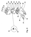
- the contact element 50 consists of a U-shaped spring element 57 on the arc section 58, a contact pin 52 is fixed.
- the contact surface 54 is provided with pyramidal tips, which put on the final assembly directly on the flat connecting conductor 4 and receive the flow of solar elements to a consumer.
- the terminal ends of the spring elements 57 are designed as pin-shaped connection ends 56 and are inserted into holes 36 on the circuit board 35 and soldered.
- the legs of the spring elements are guided in longitudinal slots 31 of the cover plate 30, while the contact pin 52 is held in a guide bore 23 in the contact housing 20.
- a negative polarization form 25 is formed in the contact housing 20 to the provided in the contact plate 10 polarization 15, which allows only a correct placement of the contact housing with the contact elements 50 on the contact plate 10 in the laminated pane 1, 2, 3.
- latching hooks 33 are provided, which engage in a mounting of the contact housing 20 with the cover plate 30, in latching openings 26 in the contact housing 20, so that the contact housing 20 with the contact element 50 and the cover plate 30 on the circuit board 35th form a unit.
- a central bore is provided, through which a screw 43 through the bores 34, 32, 22 of printed circuit board 35, cover plate 30 and contact housing 20 when mounting the connection housing to the solar power module is.
- Fig. 5 an assembled, latched housing 20 is mounted on the circuit board 35 shown.
- the contact elements protrude with the Contact pins 52 out of the contact housing, both elements due to the resilient property of the U-shaped spring element 57 independently can slide axially from each other in their guide holes 23.
- connection cables 38 are provided on the circuit board, which with Connection contacts 37 are provided.
- components 39 be provided on the circuit board.
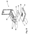
- FIG. 6 shows a connection housing 40 embodied rectangular in the extended state, consisting of a lower housing part 41 and a hinged housing cover 42.
- the housing cover 42 is rotatably supported by the legs 47 on the pins 49, while the leg 48 in cooperation with the pin 49 'causes a latching position of the cover in the open state.
- the lower housing part has an opening 46, into which the contact housing 20 is to be inserted with the printed circuit board 35, while the connection contacts 37 are to be connected to the connection plugs 60.
- the lower housing part and the housing cover are tightly closed by means of a screw 44 which can be screwed into a threaded bore 45, as well as a circumferential seal not shown between housing and cover, and as far as possible protected against environmental influences.
- connection housing The assembly of the connection housing is shown in FIG. 8.
- a double-sided adhesive film 70 with a recess 72 for the area in which the collar 41 'protrudes from the lower housing part, glued and then the terminal housing 40 placed on the area of the solar power module, in which the contact plate 10th is fixed in the disk composite 1,2,3.
- the terminal housing 40 is first placed without the contact housing 20 on the disc assembly. Only then is the insertion of the contact housing and the screwing by means of the screw 43 to the contact plate 10th
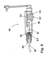
- FIG. 9 shows a section through the opened connection housing 40 in an area where one of the connection plugs 60 is plugged into the connection housing. It can thus be seen how the current is drawn off via the protruding contact pin 52 in the contact housing 20 to the printed circuit board 35 via the connecting cable 38, to the connection contact 37 and to the connection region 63 in the connection plug 60, which is embodied here by means of a cage tension spring 62 and further to the in the Cage tension spring fixed connection line 65 is passed.
- the cage tension spring can also be provided with an axial connection for stranded conductor in the connector 60.
Landscapes
- Photovoltaic Devices (AREA)
- Coupling Device And Connection With Printed Circuit (AREA)
- Connector Housings Or Holding Contact Members (AREA)
- Details Of Connecting Devices For Male And Female Coupling (AREA)
Abstract
Description
Da die aus Kupfer gefertigten Verbindungsleiter für eine durch Druck erzeugte Verbindungsart relativ weich sind, sind die Verbindungsleiter mit einem Versteifungselement unterlegt, so dass die Verbindungsleiter, die zudem noch in einer ebenfalls relativ weichen Kunststoffschicht im Scheibenverbund eingelegt sind, einen entsprechenden Gegendruck zu den Kontaktstiften ausbilden.
Dabei ist von besonderem Vorteil, dass die Kontaktstifte an einem Federelement gehalten sind und somit auch einen stetigen Druck gegen die Verbindungsleiter aufrechterhalten, so dass erhöhte Übergangswiderstände vermieden werden.
An den Versteifungselementen sind weiterhin Rastmittel vorgesehen, die mit Rastmitteln einer isolierenden Kontaktplatte in Eingriff stehen.
Die Kontaktplatte ist mit einer angeformten Grundplatte versehen, die zwischen den Scheiben gehalten ist, wobei ein kragenförmiges Anschlussteil der Kontaktplatte innerhalb einer Ausnehmung einer der Scheiben eine Verbindung mit einem Anschlussgehäuse ermöglicht, das auf die Ausnehmung der Scheibe aufgesetzt wird. Dabei werden die vorteilhafterweise federnd in dem Anschlussgehäuse gehaltenen Kontaktstifte gegen die Verbindungsleiter im Scheibenverbund gedrückt.
Da die Kontaktplatte innerhalb des Scheibenverbundes maximal die Höhe der äußeren Scheibe aufweist, also diese nicht überragt, können vorteilhafter mehrere Scheiben mit Solarstrommodulen für die Lagerung oder einen Transport direkt aufeinandergestapelt werden, da zur Abdeckung der Ausnehmung zunächst lediglich eine Schutzkappe gegen Schmutz und dergleichen vorgesehen ist, die nach der Montage des Solarstrommoduls entfernt wird und durch das Anschlussgehäuse ersetzt wird.
Vorzugsweise ist die Gesamthöhe der Kontaktplatte jedoch niedriger vorgesehen, um das Anschlussgehäuse mit einem daran angefügten Kragen für eine polarisierte Aufnahme in der Ausnehmung im Scheibenverbund einzufügen.
Die Kontaktstifte sind wiederum elektrisch leitend mit einer im Anschlussgehäuse vorgesehenen Leiterplatte verbunden, von der eine elektrische Verbindung zu einem Anschlussstecker vorgesehen ist, der vorteilhafterweise einen werkzeugloser Schnellanschluss mit einem externen Verbindungskabel aufweist und hier in Form einer Käfigzugfeder ausgeführt ist.
Dabei ist das Anschlussgehäuse mit den Kontaktstiften vorteilhafterweise in einer spritzwasser- und staubdichten Version vorgesehen, um unabhängig von Umwelteinflüssen eine sichere elektrische Verbindung zwischen den Solarelementen und einem Verbraucher zu realisieren.
- Fig. 1
- die Montage einer Kontaktplatte in einem Scheibenverbund eines Solarstrommoduls,
- Fig. 2
- eine Detaildarstellung der Kontaktplatte,
- Fig. 3
- eine Kontaktplatte fertig montiert im Scheibenverbund,
- Fig. 4
- eine auseinandergezogene Darstellung des Kontaktgehäuses,
- Fig. 5
- ein auf einer Leiterplatte montiertes Kontaktgehäuse mit Kontaktstiften,
- Fig. 6
- eine auseinandergezogene Darstellung des Anschlussgehäuses,
- Fig. 7
- eine Bodenansicht des Anschlussgehäuses,
- Fig. 8
- eine Montageansicht des Anschlussgehäuses auf dem Scheibenverbund, und
- Fig. 9
- eine Schnittdarstellung durch das Anschlussgehäuse mit einem Anschlussstecker.
Von den Solarelementen sind flache Verbindungsleiter 4 zu einem zentralen Übergabepunkt geführt, an dem eine als flaches Gehäuseteil ausgebildete Kontaktplatte 10 angeordnet ist.
Die Verbindungsleiter 4 sind in Leiterkanälen 8 in der Kunststoffschicht 2 eingelegt und an ihren Enden von teilweise umgreifenden Versteifungselementen 5 umgeben.
Die Kontaktplatte 10 ist als flaches, rechteckiges Formteil ausgeführt und weist eine Grundplatte 12 auf, auf der eine Struktur verschiedener Formgebungen vorgesehen ist, die von einem Kragen 18 umgeben ist.
Die Kontaktplatte wird oberhalb der Verbindungsleiter 4 in einer der Grundplatte entsprechenden Ausformung 7 auf der Kunststoffschicht 2 aufgelegt, wobei an den Versteifungselementen 5 vorgesehene Rastmittel 6 in der Kontaktplatte je an einem Hinterschnitt 16 verrasten.
Als Schutz gegen ein Eindringen von Schmutz bei einem Transport des Scheibenverbundes, kann die Ausnehmung mit einem Schutzdeckel o. ä. abgedeckt werden, wobei gewährleistet ist, dass die maximale Höhe der Kontaktplatte 10 die Scheibendicke nicht überschreitet. Normalerweise ist die Höhe des Kragens kürzer als die Dicke der Scheibe 3 des Scheibenverbundes
Das Kontaktelement 50 besteht aus einem U-förmig ausgebildeten Federelement 57 auf dessen Bogenabschnitt 58 ein Kontaktstift 52 fixiert ist.
Die Anschlussenden der Federelemente 57 sind als stiftförmige Anschlussenden 56 ausgeführt und werden in Bohrungen 36 auf der Leiterplatte 35 eingesetzt und verlötet.
Zur Fixierung sind die Schenkel der Federelemente in Längsschlitzen 31 der Deckelplatte 30 geführt, während der Kontaktstift 52 in einer Führungsbohrung 23 im Kontaktgehäuse 20 gehalten ist.
Zwischen den beiden Führungsbohrungen 23 ist in dem Kontaktgehäuse 20 eine negative Polarisationsform 25 zu der in der Kontaktplatte 10 vorgesehenen Polarisation 15 eingeformt, die nur ein korrektes Aufsetzen des Kontaktgehäuses mit den Kontaktelementen 50 auf die Kontaktplatte 10 im Scheibenverbund 1, 2, 3 zulässt.
An der Deckelplatte 30 sind weiterhin nach außen weisende Rasthaken 33 vorgesehen, die bei einer Montage des Kontaktgehäuses 20 mit der Deckelplatte 30, in Rastöffnungen 26 im Kontaktgehäuse 20 eingreifen, so dass das Kontaktgehäuse 20 mit dem Kontaktelement 50 und der Deckelplatte 30 auf der Leiterplatte 35 eine Einheit bilden.
Durch das gesamte montierte Gebilde von Kontaktgehäuse 20, Deckelplatte 30 und Leiterplatte 35 ist eine Zentralbohrung vorgesehen, durch die bei der Montage des Anschlussgehäuses auf das Solarstrommodul eine Schraube 43 durch die Bohrungen 34, 32, 22 von Leiterplatte 35, Deckelplatte 30 und Kontaktgehäuse 20 geführt ist.
Die Gehäuseabdeckung 42 ist mit den Schenkeln 47 an den Stiften 49 drehbar gehalten, während der Schenkel 48 in Zusammenspiel mit dem Stift 49' im geöffneten Zustand eine Einrastposition der Abdeckung bewirkt.
Das Gehäuseunterteil weist eine Öffnung 46 auf, in die das Kontaktgehäuse 20 mit der Leiterplatte 35 einzusetzen ist, während die Anschlusskontakte 37 mit den Anschlusssteckern 60 zu verbinden sind.
Das Gehäuseunterteil und die Gehäuseabdeckung sind mittels einer Schraube 44, die in einer Gewindebohrung 45 einschraubbar ist, sowie einer nicht weiter gezeigten umlaufenden Dichtung zwischen Gehäuse und Abdeckung dicht zu verschließen, und so weitestgehend gegen Umwelteinflüsse geschützt.
Das Anschlussgehäuse 40 wird zunächst ohne das Kontaktgehäuse 20 auf den Scheibenverbund aufgesetzt. Erst danach erfolgt das Einsetzen des Kontaktgehäuses und das Verschrauben mittels der Verschraubung 43 an der Kontaktplatte 10.
So ist erkennbar wie die Stromabnahme über den herausragenden Kontaktstift 52 im Kontaktgehäuse 20 zu der Leiterplatte 35 über das Verbindungskabel 38, zu dem Anschlusskontakt 37 und zum Anschlussbereich 63 im Anschlussstecker 60 erfolgt, der hier mittels einer Käfigzugfeder 62 ausgeführt ist und weiter an die in der Käfigzugfeder fixierte Anschlussleitung 65 geleitet wird.
Anstelle der Käfigzugfeder kann auch eine Verbindung mit einem axialen Anschluss für Litzenleiter in dem Anschlussstecker 60 vorgesehen sein.
Claims (10)
- Anschlusseinrichtung in einem Anschlussgehäuse (40) für ein Solarstrommodul zur Verbindung einer elektrischen Anschlussleitung (65) mit elektrischen Verbindungsleitern (4) des Solarstrommoduls, die innerhalb eines transluciden Scheibenverbundes (1, 2, 3) angeordnet sind und mehrere photovoltaische Solarelemente miteinander elektrisch verbinden, dadurch gekennzeichnet, dass die Enden der Verbindungsleiter (4) teilweise von einem Versteifungselement (5) unterstützt sind, und
dass die Verbindungsleiter (4) im Bereich der Unterstützung des Versteifungselementes (5) mit jeweils einem Kontaktstift (52) kontaktierbar sind. - Anschlusseinrichtung nach Anspruch 1, dadurch gekennzeichnet, dass das Versteifungselement (5) U-förmig ausgebildet ist.
- Anschlusseinrichtung nach Anspruch 1 oder 2, dadurch gekennzeichnet, dass das Versteifungselement (5) mit Rastmitteln (6) versehen ist, die an einer Hinterschneidung (16) in einer Kontaktplatte (10) verrasten, wobei die Kontaktplatte (10) in einer Ausformung (7) der transluciden Kunststoffschicht (2) fixiert ist, die zwischen den Scheiben (1, 3) des Scheibenverbundes angeordnet ist.
- Anschlusseinrichtung nach einem der vorstehenden Ansprüche, dadurch gekennzeichnet, dass der Kontaktstift (52) eine Kontaktfläche (54) mit einer Vielzahl pyramidenförmiger Spitzen aufweist.
- Anschlusseinrichtung nach einem der vorstehenden Ansprüche, dadurch gekennzeichnet, dass der Kontaktstift (52) mittig und nach außen weisend auf einem Bogenabschnitt (58) eines U-förmig gebogenen Federelementes (57) angeordnet ist.
- Anschlusseinrichtung nach einem der vorstehenden Ansprüche, dadurch gekennzeichnet, dass das Federelement (57) zwei Anschlussenden (56) aufweist, die jeweils in einem Längsschlitz (31) einer Deckelplatte (30) geführt sind und mit einer Leiterplatte (35) elektrisch leitend verbunden sind.
- Anschlusseinrichtung nach einem der vorstehenden Ansprüche, dadurch gekennzeichnet, dass die Deckelplatte (30) mit einem Kontaktgehäuse (20) verrastbar ist, wobei die Kontaktstifte (52) des Kontaktelementes (50) im Kontaktgehäuse (20) innerhalb einer Durchgangsbohrung (23) geführt sind.
- Anschlusseinrichtung nach einem der vorstehenden Ansprüche, dadurch gekennzeichnet, dass das Kontaktgehäuse (20), mit den Kontaktelementen (50), der Deckelplatte (30), und der Leiterplatte (35) als Einheit zusammengefügt sind und in dem Anschlussgehäuse (40) in eine Ausnehmung (46) eintauchen und mittels einer Schraubverbindung 43 an der Kontaktplatte 10 im Scheibenverbund fixierbar ist.
- Anschlusseinrichtung nach einem der vorstehenden Ansprüche, dadurch gekennzeichnet, dass das Anschlussgehäuse (40), die Kontaktplatte (10) in der Ausnehmung (9) abdeckend, mittels einer doppelseitigen Klebefolie (70) auf der Scheibe (3) des Scheibenverbundes (1, 2, 3) fixiert ist.
- Anschlusseinrichtung nach einem der vorstehenden Ansprüche, dadurch gekennzeichnet, dass an dem Anschlussgehäuse (40) Anschlussstecker (60) vorgesehen sind, so dass mittels je einer im Anschlussstecker angeordneten Käfigzugfeder (62), eine lösbare Verbindung zwischen der elektrischen Anschlussleitung (65) und den auf der Leiterplatte (35) im Anschlussgehäuse vorgesehenen Verbindungskabelstück (38) herstellbar ist.
Applications Claiming Priority (2)
| Application Number | Priority Date | Filing Date | Title |
|---|---|---|---|
| DE10334935 | 2003-07-31 | ||
| DE10334935A DE10334935B3 (de) | 2003-07-31 | 2003-07-31 | Anschlusseinrichtung für ein Solarstrommodul |
Publications (3)
| Publication Number | Publication Date |
|---|---|
| EP1503426A2 true EP1503426A2 (de) | 2005-02-02 |
| EP1503426A3 EP1503426A3 (de) | 2008-08-13 |
| EP1503426B1 EP1503426B1 (de) | 2011-02-02 |
Family
ID=33483094
Family Applications (1)
| Application Number | Title | Priority Date | Filing Date |
|---|---|---|---|
| EP04014478A Expired - Lifetime EP1503426B1 (de) | 2003-07-31 | 2004-06-21 | Anschlusseinrichtung für ein Solarstrommodul |
Country Status (8)
| Country | Link |
|---|---|
| US (1) | US7655859B2 (de) |
| EP (1) | EP1503426B1 (de) |
| JP (1) | JP3896370B2 (de) |
| CN (1) | CN100343999C (de) |
| AT (1) | ATE497640T1 (de) |
| CA (1) | CA2475184C (de) |
| DE (2) | DE10334935B3 (de) |
| ES (1) | ES2360359T3 (de) |
Cited By (4)
| Publication number | Priority date | Publication date | Assignee | Title |
|---|---|---|---|---|
| DE102009060306A1 (de) * | 2009-12-23 | 2011-06-30 | Yamaichi Electronics Deutschland GmbH, 81829 | Solarmodul, Anschlußdose, Solarmodulverbinderanordnung, Verfahren und Verwendung |
| WO2012168330A1 (de) | 2011-06-08 | 2012-12-13 | Hirschmann Automotive Gmbh | Photovoltaik-paneldose mit verbesserten aussenanschlüssen |
| EP2674988A1 (de) | 2012-06-13 | 2013-12-18 | Hirschmann Automotive GmbH | Photovoltaik-Paneldose mit Klemmkontaktierung der Bändchen des Solarelementes |
| US9331631B2 (en) | 2012-08-31 | 2016-05-03 | First Solar, Inc. | Direct connection of lead bar to conductive ribbon in a thin film photovoltaic device |
Families Citing this family (48)
| Publication number | Priority date | Publication date | Assignee | Title |
|---|---|---|---|---|
| DE102005024644A1 (de) | 2005-05-25 | 2006-11-30 | G. Spelsberg Gmbh & Co. Kg | Elektrische Anschluß- und Verbindungsdose |
| PL2059951T3 (pl) * | 2006-05-15 | 2015-11-30 | Antaya Tech Corporation | Zespół złącza elektrycznego |
| CN101461109A (zh) * | 2006-06-29 | 2009-06-17 | 胡贝尔和茹纳股份公司 | 接线盒 |
| DE102007027861A1 (de) * | 2006-10-04 | 2008-04-10 | Günther Spelsberg GmbH & Co. KG | Montageset für eine Elektrodose |
| DE102007020843A1 (de) * | 2007-03-28 | 2008-10-02 | Günther Spelsberg GmbH & Co. KG | Paneldose |
| DE202007005126U1 (de) * | 2007-04-04 | 2008-08-14 | Weidmüller Interface GmbH & Co. KG | Elektrische Anschlußvorrichtung für Kontakte, insbesondere Messerkontakte |
| ATE526687T1 (de) * | 2007-04-13 | 2011-10-15 | Huber+Suhner Ag | Anschlussdosen |
| US10468993B2 (en) * | 2007-05-17 | 2019-11-05 | Enphase Energy, Inc. | Inverter for use in photovoltaic module |
| US20090084426A1 (en) * | 2007-09-28 | 2009-04-02 | Enphase Energy, Inc. | Universal interface for a photovoltaic module |
| DE102008022297B4 (de) * | 2008-03-13 | 2011-04-14 | Fpe Fischer Gmbh | Verbindungsbox für Solar-Module und Verfahren zu deren Montage an den Modulen |
| DE102008022051A1 (de) * | 2008-05-03 | 2009-11-19 | Lumberg Connect Gmbh | Anschlussdose für ein Solarmodul |
| DE202009004930U1 (de) * | 2008-09-22 | 2010-03-04 | Weidmüller Interface GmbH & Co. KG | Elektrische Anschlussvorrichtung für Flachleiter |
| US7938661B2 (en) * | 2008-10-29 | 2011-05-10 | Tyco Electronics Corporation | Photovoltaic module connector assembly |
| WO2010054841A2 (de) * | 2008-11-17 | 2010-05-20 | Hirschmann Automation And Control Gmbh | Photovoltaik-komponenten |
| DE102008062034B4 (de) * | 2008-12-12 | 2010-08-12 | Tyco Electronics Amp Gmbh | Verbindungsvorrichtung zum Anschluss an ein Solarmodul und Solarmodul mit einer solchen Verbindungsvorrichtung |
| TWI419346B (zh) * | 2009-01-20 | 2013-12-11 | Ks Terminals Inc | 太陽能電池模組及連接器組成 |
| DE202009001493U1 (de) * | 2009-02-06 | 2010-06-24 | Weidmüller Interface GmbH & Co. KG | Anschlussgehäuse |
| FI122521B (fi) * | 2009-04-15 | 2012-03-15 | Sk Tuote Oy | Laite aurinkokennon putkijohtojen läpivientiä varten |
| US8435056B2 (en) * | 2009-04-16 | 2013-05-07 | Enphase Energy, Inc. | Apparatus for coupling power generated by a photovoltaic module to an output |
| DE102009039370B4 (de) * | 2009-05-20 | 2013-12-05 | Gp Solar Gmbh | Solarzellenmodul mit zumindest einer Laminatfolie, einer weiteren Laminatfolie und einem Querverbinder sowie Verfahren zur Verschaltung von Solarzellen in einem Solarzellenmodul |
| CN101894869B (zh) * | 2009-05-22 | 2012-07-25 | 健和兴端子股份有限公司 | 太阳能电池模块及连接器组成 |
| US7963802B2 (en) | 2009-06-30 | 2011-06-21 | Miasole | External electrical connectors for solar modules |
| EP2273561A1 (de) * | 2009-07-09 | 2011-01-12 | OJA-Services | Thermische Montage von Elektronik auf ein Photovoltaikpaneel |
| US20110005576A1 (en) * | 2009-07-10 | 2011-01-13 | Melvin James Bullen | Personal solar appliance |
| US8558102B2 (en) | 2009-09-11 | 2013-10-15 | Miasole | Rotatable junction box for a solar module |
| US20100139742A1 (en) * | 2009-10-12 | 2010-06-10 | Wayman Elizabeth N | Photovoltaic Module Assembly With Integrated Junctions |
| US7918694B1 (en) * | 2010-03-01 | 2011-04-05 | Tyco Electronics Corporation | Connector assembly for solar shingles |
| US8572836B2 (en) | 2010-04-19 | 2013-11-05 | Sunpower Corporation | Method of manufacturing a large-area segmented photovoltaic module |
| AT12058U1 (de) * | 2010-04-27 | 2011-09-15 | Austria Tech & System Tech | Verfahren zum kontaktieren eines photovoltaischen moduls mit einem anschlussgehäuse sowie system bestehend aus einem photovoltaischen modul und einem anschlussgehäuse |
| US20120152325A1 (en) * | 2010-06-21 | 2012-06-21 | Global Solar Energy, Inc. | Junction box attachment to solar module laminate |
| DE102010041032A1 (de) * | 2010-09-20 | 2012-03-22 | Robert Bosch Gmbh | Anschlusskontaktanordnung und Solarzellenanordnung |
| JPWO2012043702A1 (ja) * | 2010-09-30 | 2014-02-24 | シャープ株式会社 | 太陽電池モジュール |
| DE102010043909A1 (de) * | 2010-11-15 | 2012-05-16 | Robert Bosch Gmbh | Anschlussdose eines Solarzellenmoduls, Solarzellenmodul und Verfahren zu dessen Herstellung |
| US20120125395A1 (en) * | 2010-11-24 | 2012-05-24 | First Solar, Inc | Method and apparatus facilitating electrical interconnection of a plurality of solar modules |
| JP5674443B2 (ja) * | 2010-12-08 | 2015-02-25 | 株式会社東芝 | 太陽電池モジュールおよび太陽電池モジュールのコネクタ |
| DE102011011715B4 (de) * | 2011-02-18 | 2013-09-05 | Yamaichi Electronics Deutschland Gmbh | Anschlußdose, Verfahren zum Herstellen sowie Verwendung der Anschlußdose |
| EP2684219A1 (de) * | 2011-03-08 | 2014-01-15 | Kingspan Research and Developments Limited | Isolierverbundplatte |
| CN103828228A (zh) * | 2011-07-18 | 2014-05-28 | 恩菲斯能源公司 | 用于光伏模块的弹性安装组件 |
| JP5905108B2 (ja) * | 2011-09-30 | 2016-04-20 | サン−ゴバン グラス フランスSaint−Gobain Glass France | 接続ソケットを備えたソーラーモジュール並びにその製造方法 |
| JP5729648B2 (ja) * | 2011-10-13 | 2015-06-03 | ホシデン株式会社 | 太陽電池モジュール用端子ボックス |
| JP5790940B2 (ja) * | 2011-12-19 | 2015-10-07 | ホシデン株式会社 | 端子ボックス |
| KR101283115B1 (ko) * | 2011-12-26 | 2013-07-05 | 엘지이노텍 주식회사 | 커넥터 및 이를 포함하는 태양전지 모듈 |
| EP2672527B1 (de) | 2012-06-07 | 2019-09-18 | Hanwha Q CELLS GmbH | Solarmodul mit einer Steckeinrichtung |
| USD734653S1 (en) | 2012-11-09 | 2015-07-21 | Enphase Energy, Inc. | AC module mounting bracket |
| WO2014086914A1 (de) * | 2012-12-06 | 2014-06-12 | Saint-Gobain Glass France | Solarmodul mit anschlussdose |
| CN104078523B (zh) * | 2013-03-25 | 2016-08-31 | 讯芯电子科技(中山)有限公司 | 聚光光电芯片封装结构及制作方法 |
| JP6136005B2 (ja) * | 2013-06-04 | 2017-05-31 | 住友電気工業株式会社 | 太陽電池モジュール |
| US9685730B2 (en) | 2014-09-12 | 2017-06-20 | Steelcase Inc. | Floor power distribution system |
Family Cites Families (20)
| Publication number | Priority date | Publication date | Assignee | Title |
|---|---|---|---|---|
| FR2362494A1 (fr) * | 1976-04-26 | 1978-03-17 | Radiotechnique Compelec | Perfectionnement aux panneaux de photopiles solaires |
| US4283106A (en) | 1980-02-01 | 1981-08-11 | Amp Incorporated | Symmetrical connector for solar panel arrays |
| US4457578A (en) | 1981-12-21 | 1984-07-03 | Atlantic Richfield Company | Electrical terminal for solar panel |
| US4460232A (en) * | 1982-05-24 | 1984-07-17 | Amp, Incorporated | Junction box for solar modules |
| US4830038A (en) * | 1988-01-20 | 1989-05-16 | Atlantic Richfield Company | Photovoltaic module |
| US5137461A (en) * | 1988-06-21 | 1992-08-11 | International Business Machines Corporation | Separable electrical connection technology |
| US5110369A (en) * | 1990-10-24 | 1992-05-05 | Mobil Solar Energy Corporation | Cable interconnections for solar cell modules |
| EP0521189A1 (de) * | 1991-07-05 | 1993-01-07 | Siemens Solar GmbH | Elektrisches Anschlusselement für ein Solarmodul |
| US5201855A (en) * | 1991-09-30 | 1993-04-13 | Ikola Dennis D | Grid system matrix for transient protection of electronic circuitry |
| US5513075A (en) * | 1992-05-08 | 1996-04-30 | The Whitaker Corporation | Module for electrically connecting conductor wires to circuits of flat surfaces such as solar panels |
| US5503684A (en) * | 1994-12-30 | 1996-04-02 | Silicon Energy Corporation | Termination system for solar panels |
| US6462265B1 (en) * | 1995-08-15 | 2002-10-08 | Canon Kabushiki Kaisha | Terminal lead-out structure and solar-cell apparatus provided with such structure |
| JP3838381B2 (ja) * | 1995-11-22 | 2006-10-25 | 株式会社アドバンテスト | プローブカード |
| JP3357808B2 (ja) * | 1996-01-29 | 2002-12-16 | 三洋電機株式会社 | 太陽電池装置 |
| JP2000133356A (ja) * | 1998-10-28 | 2000-05-12 | Japan Aviation Electronics Industry Ltd | ソケットコンタクト |
| AU773619B2 (en) | 1998-12-04 | 2004-05-27 | Scheuten Solar Technology Gmbh | Photovoltaic solar module in plate form |
| JP2000357812A (ja) | 1999-04-15 | 2000-12-26 | Canon Inc | 太陽電池モジュール及び発電装置 |
| US6582249B1 (en) * | 1999-11-17 | 2003-06-24 | Tyco Electronics Amp Gmbh | Apparatus for contacting foil conductors, in particular of a solar module |
| US6419504B1 (en) * | 2001-04-17 | 2002-07-16 | Richard Bryant Nelson | Slide locked retractable grounding pin power cord plug |
| DE10154234A1 (de) * | 2001-11-07 | 2003-05-22 | Kostal Leopold Gmbh & Co Kg | Anordnung bestehend aus einem paneelartig aufgebauten Modul und aus einer Anschlußeinheit, Anschlußeinheit für eine solche Anordnung, Verfahren zum Erstellen einer solchen Anordnung sowie Vorrichtung zum Herstellen einer solchen Anordnung |
-
2003
- 2003-07-31 DE DE10334935A patent/DE10334935B3/de not_active Expired - Fee Related
-
2004
- 2004-06-21 ES ES04014478T patent/ES2360359T3/es not_active Expired - Lifetime
- 2004-06-21 EP EP04014478A patent/EP1503426B1/de not_active Expired - Lifetime
- 2004-06-21 DE DE502004012160T patent/DE502004012160D1/de not_active Expired - Lifetime
- 2004-06-21 AT AT04014478T patent/ATE497640T1/de active
- 2004-07-01 US US10/883,103 patent/US7655859B2/en not_active Expired - Fee Related
- 2004-07-19 CA CA2475184A patent/CA2475184C/en not_active Expired - Fee Related
- 2004-07-28 JP JP2004220798A patent/JP3896370B2/ja not_active Expired - Fee Related
- 2004-07-30 CN CNB2004100587712A patent/CN100343999C/zh not_active Expired - Fee Related
Cited By (12)
| Publication number | Priority date | Publication date | Assignee | Title |
|---|---|---|---|---|
| DE102009060306A1 (de) * | 2009-12-23 | 2011-06-30 | Yamaichi Electronics Deutschland GmbH, 81829 | Solarmodul, Anschlußdose, Solarmodulverbinderanordnung, Verfahren und Verwendung |
| WO2012168330A1 (de) | 2011-06-08 | 2012-12-13 | Hirschmann Automotive Gmbh | Photovoltaik-paneldose mit verbesserten aussenanschlüssen |
| DE102012209575A1 (de) | 2011-06-08 | 2012-12-13 | Hirschmann Automotive Gmbh | Photovoltaik-Paneldose mit verbesserten Aussenanschlüssen |
| WO2012168327A1 (de) | 2011-06-08 | 2012-12-13 | Hirschmann Automotive Gmbh | Photovoltaik-paneldose mit verbesserter interner kontaktierung |
| DE102012209572A1 (de) | 2011-06-08 | 2012-12-13 | Hirschmann Automotive Gmbh | Photovoltaik-Paneldose mit verbesserter interner Kontaktierung |
| WO2012168328A1 (de) | 2011-06-08 | 2012-12-13 | Hirschmann Automotive Gmbh | Photovoltaik-paneldose mit verbessertem gehäuse |
| DE102012209571A1 (de) | 2011-06-08 | 2012-12-13 | Hirschmann Automotive Gmbh | Photovoltaik-Paneldose mit verbessertem Gehäuse |
| DE102012209576A1 (de) | 2011-06-08 | 2012-12-13 | Hirschmann Automotive Gmbh | hotovoltaik-Paneldose mit optimiertem Wärmehaushalt |
| WO2012168329A1 (de) | 2011-06-08 | 2012-12-13 | Hirschmann Automotive Gmbh | Photovoltaik-paneldose mit optimiertem wärmehaushalt |
| EP2674988A1 (de) | 2012-06-13 | 2013-12-18 | Hirschmann Automotive GmbH | Photovoltaik-Paneldose mit Klemmkontaktierung der Bändchen des Solarelementes |
| DE102013211054A1 (de) | 2012-06-13 | 2013-12-19 | Hirschmann Automotive Gmbh | Photovoltaik-Paneldose mit Klemmkontaktierung der Bändchen des Solarelementes |
| US9331631B2 (en) | 2012-08-31 | 2016-05-03 | First Solar, Inc. | Direct connection of lead bar to conductive ribbon in a thin film photovoltaic device |
Also Published As
| Publication number | Publication date |
|---|---|
| CA2475184A1 (en) | 2005-01-31 |
| EP1503426A3 (de) | 2008-08-13 |
| ATE497640T1 (de) | 2011-02-15 |
| US20050022859A1 (en) | 2005-02-03 |
| DE10334935B3 (de) | 2004-12-23 |
| US7655859B2 (en) | 2010-02-02 |
| CN100343999C (zh) | 2007-10-17 |
| CA2475184C (en) | 2010-05-11 |
| CN1581516A (zh) | 2005-02-16 |
| JP3896370B2 (ja) | 2007-03-22 |
| DE502004012160D1 (de) | 2011-03-17 |
| ES2360359T3 (es) | 2011-06-03 |
| EP1503426B1 (de) | 2011-02-02 |
| JP2005057274A (ja) | 2005-03-03 |
Similar Documents
| Publication | Publication Date | Title |
|---|---|---|
| EP1503426B1 (de) | Anschlusseinrichtung für ein Solarstrommodul | |
| DE102005021835B4 (de) | Solarzellenmodul-Verbindungsglied und Verfahren zum Herstellen eines Solarzellenmodul-Panels | |
| DE202005018884U1 (de) | Anschlussdose für ein Solarpaneel sowie Solarpaneel mit einer solchen Anschlussdose | |
| EP2294624B1 (de) | Anschlussdose für photovoltaische Module | |
| DE69400313T3 (de) | Verbinder für übertragungsleitung und zusammenbau desselben | |
| DE19816695C2 (de) | Spannungsversorgungs-Buchse | |
| DE20311183U1 (de) | Anschlussdose für ein Solarpaneel und Solarpaneel | |
| WO2006074561A1 (de) | Anschlussdose für ein solarpaneel sowie solarpaneel mit einer anschlussdose | |
| DE102009055882A1 (de) | Leistungshalbleitervorrichtung | |
| EP2115838A1 (de) | Anschluss- und verbindungsdose für ein solarmodul | |
| WO2008095668A1 (de) | Anschluss- und verbindungsdose für ein solarmodul | |
| DE102007031351A1 (de) | Verbindungsvorrichtung zur Verbindung eines ersten elektrischen Leiters mit einem elektrischen Leiter eines photovoltaischen Solarmoduls | |
| DE102008023108A1 (de) | Kantenverbinder für ein Solarmodul, Steckverbinder zur Verbindung mit dem Kantenverbinder sowie Solarmodul mit einem derartigen Kantenverbinder | |
| DE102009001654A1 (de) | Netzanschlussleitung und Elektrogerät | |
| DE20108985U1 (de) | Anschluß für Drähte | |
| DE102012104549B4 (de) | Variierbarer Stecker eines Steckverbinders | |
| EP1727240B1 (de) | Elektrische Anschluss- und Verbindungsdose | |
| DE102008059000A1 (de) | Elektrischer Steckverbinder | |
| DE102015218526B4 (de) | Anschlussanordnung für ein Solarmodul | |
| DE10053302A1 (de) | Mehrpoliger elektrischer Anschlußverbinder | |
| DE102009004100A1 (de) | Solarpaneel und Verfahren | |
| EP1429420B1 (de) | Anschlusseinrichtung, insbesondere für elektrische Betriebsmittel | |
| EP2490266B1 (de) | Anschlussdose, Verfahren zum Herstellen sowie Verwendung der Anschlussdose | |
| DE10318980A1 (de) | Steckverbinder zur elektrischen Verbindung elektronischer Komponenten | |
| DE202011002913U1 (de) | Anschlußdose |
Legal Events
| Date | Code | Title | Description |
|---|---|---|---|
| PUAI | Public reference made under article 153(3) epc to a published international application that has entered the european phase |
Free format text: ORIGINAL CODE: 0009012 |
|
| AK | Designated contracting states |
Kind code of ref document: A2 Designated state(s): AT BE BG CH CY CZ DE DK EE ES FI FR GB GR HU IE IT LI LU MC NL PL PT RO SE SI SK TR |
|
| AX | Request for extension of the european patent |
Extension state: AL HR LT LV MK |
|
| PUAL | Search report despatched |
Free format text: ORIGINAL CODE: 0009013 |
|
| AK | Designated contracting states |
Kind code of ref document: A3 Designated state(s): AT BE BG CH CY CZ DE DK EE ES FI FR GB GR HU IE IT LI LU MC NL PL PT RO SE SI SK TR |
|
| AX | Request for extension of the european patent |
Extension state: AL HR LT LV MK |
|
| RIC1 | Information provided on ipc code assigned before grant |
Ipc: H01R 13/24 20060101ALI20080708BHEP Ipc: H01L 31/05 20060101AFI20040913BHEP |
|
| 17P | Request for examination filed |
Effective date: 20081107 |
|
| AKX | Designation fees paid |
Designated state(s): AT BE BG CH CY CZ DE DK EE ES FI FR GB GR HU IE IT LI LU MC NL PL PT RO SE SI SK TR |
|
| 17Q | First examination report despatched |
Effective date: 20090507 |
|
| GRAP | Despatch of communication of intention to grant a patent |
Free format text: ORIGINAL CODE: EPIDOSNIGR1 |
|
| GRAS | Grant fee paid |
Free format text: ORIGINAL CODE: EPIDOSNIGR3 |
|
| GRAA | (expected) grant |
Free format text: ORIGINAL CODE: 0009210 |
|
| AK | Designated contracting states |
Kind code of ref document: B1 Designated state(s): AT BE BG CH CY CZ DE DK EE ES FI FR GB GR HU IE IT LI LU MC NL PL PT RO SE SI SK TR |
|
| REG | Reference to a national code |
Ref country code: GB Ref legal event code: FG4D Free format text: NOT ENGLISH |
|
| REG | Reference to a national code |
Ref country code: CH Ref legal event code: EP |
|
| REG | Reference to a national code |
Ref country code: IE Ref legal event code: FG4D Free format text: LANGUAGE OF EP DOCUMENT: GERMAN |
|
| REF | Corresponds to: |
Ref document number: 502004012160 Country of ref document: DE Date of ref document: 20110317 Kind code of ref document: P |
|
| REG | Reference to a national code |
Ref country code: DE Ref legal event code: R096 Ref document number: 502004012160 Country of ref document: DE Effective date: 20110317 |
|
| REG | Reference to a national code |
Ref country code: NL Ref legal event code: VDEP Effective date: 20110202 |
|
| REG | Reference to a national code |
Ref country code: ES Ref legal event code: FG2A Ref document number: 2360359 Country of ref document: ES Kind code of ref document: T3 Effective date: 20110603 |
|
| PG25 | Lapsed in a contracting state [announced via postgrant information from national office to epo] |
Ref country code: GR Free format text: LAPSE BECAUSE OF FAILURE TO SUBMIT A TRANSLATION OF THE DESCRIPTION OR TO PAY THE FEE WITHIN THE PRESCRIBED TIME-LIMIT Effective date: 20110503 Ref country code: SE Free format text: LAPSE BECAUSE OF FAILURE TO SUBMIT A TRANSLATION OF THE DESCRIPTION OR TO PAY THE FEE WITHIN THE PRESCRIBED TIME-LIMIT Effective date: 20110202 Ref country code: PT Free format text: LAPSE BECAUSE OF FAILURE TO SUBMIT A TRANSLATION OF THE DESCRIPTION OR TO PAY THE FEE WITHIN THE PRESCRIBED TIME-LIMIT Effective date: 20110602 |
|
| PGFP | Annual fee paid to national office [announced via postgrant information from national office to epo] |
Ref country code: CH Payment date: 20110627 Year of fee payment: 8 Ref country code: ES Payment date: 20110607 Year of fee payment: 8 |
|
| PG25 | Lapsed in a contracting state [announced via postgrant information from national office to epo] |
Ref country code: PL Free format text: LAPSE BECAUSE OF FAILURE TO SUBMIT A TRANSLATION OF THE DESCRIPTION OR TO PAY THE FEE WITHIN THE PRESCRIBED TIME-LIMIT Effective date: 20110202 Ref country code: BG Free format text: LAPSE BECAUSE OF FAILURE TO SUBMIT A TRANSLATION OF THE DESCRIPTION OR TO PAY THE FEE WITHIN THE PRESCRIBED TIME-LIMIT Effective date: 20110502 Ref country code: NL Free format text: LAPSE BECAUSE OF FAILURE TO SUBMIT A TRANSLATION OF THE DESCRIPTION OR TO PAY THE FEE WITHIN THE PRESCRIBED TIME-LIMIT Effective date: 20110202 Ref country code: CY Free format text: LAPSE BECAUSE OF FAILURE TO SUBMIT A TRANSLATION OF THE DESCRIPTION OR TO PAY THE FEE WITHIN THE PRESCRIBED TIME-LIMIT Effective date: 20110202 Ref country code: SI Free format text: LAPSE BECAUSE OF FAILURE TO SUBMIT A TRANSLATION OF THE DESCRIPTION OR TO PAY THE FEE WITHIN THE PRESCRIBED TIME-LIMIT Effective date: 20110202 Ref country code: FI Free format text: LAPSE BECAUSE OF FAILURE TO SUBMIT A TRANSLATION OF THE DESCRIPTION OR TO PAY THE FEE WITHIN THE PRESCRIBED TIME-LIMIT Effective date: 20110202 |
|
| PGFP | Annual fee paid to national office [announced via postgrant information from national office to epo] |
Ref country code: GB Payment date: 20110616 Year of fee payment: 8 |
|
| REG | Reference to a national code |
Ref country code: IE Ref legal event code: FD4D |
|
| PG25 | Lapsed in a contracting state [announced via postgrant information from national office to epo] |
Ref country code: EE Free format text: LAPSE BECAUSE OF FAILURE TO SUBMIT A TRANSLATION OF THE DESCRIPTION OR TO PAY THE FEE WITHIN THE PRESCRIBED TIME-LIMIT Effective date: 20110202 Ref country code: IE Free format text: LAPSE BECAUSE OF FAILURE TO SUBMIT A TRANSLATION OF THE DESCRIPTION OR TO PAY THE FEE WITHIN THE PRESCRIBED TIME-LIMIT Effective date: 20110202 Ref country code: DK Free format text: LAPSE BECAUSE OF FAILURE TO SUBMIT A TRANSLATION OF THE DESCRIPTION OR TO PAY THE FEE WITHIN THE PRESCRIBED TIME-LIMIT Effective date: 20110202 |
|
| PG25 | Lapsed in a contracting state [announced via postgrant information from national office to epo] |
Ref country code: SK Free format text: LAPSE BECAUSE OF FAILURE TO SUBMIT A TRANSLATION OF THE DESCRIPTION OR TO PAY THE FEE WITHIN THE PRESCRIBED TIME-LIMIT Effective date: 20110202 Ref country code: RO Free format text: LAPSE BECAUSE OF FAILURE TO SUBMIT A TRANSLATION OF THE DESCRIPTION OR TO PAY THE FEE WITHIN THE PRESCRIBED TIME-LIMIT Effective date: 20110202 Ref country code: CZ Free format text: LAPSE BECAUSE OF FAILURE TO SUBMIT A TRANSLATION OF THE DESCRIPTION OR TO PAY THE FEE WITHIN THE PRESCRIBED TIME-LIMIT Effective date: 20110202 |
|
| PLBE | No opposition filed within time limit |
Free format text: ORIGINAL CODE: 0009261 |
|
| STAA | Information on the status of an ep patent application or granted ep patent |
Free format text: STATUS: NO OPPOSITION FILED WITHIN TIME LIMIT |
|
| PGFP | Annual fee paid to national office [announced via postgrant information from national office to epo] |
Ref country code: IT Payment date: 20110620 Year of fee payment: 8 |
|
| BERE | Be: lapsed |
Owner name: HARTING ELECTRIC G.M.B.H. & CO. KG Effective date: 20110630 |
|
| 26N | No opposition filed |
Effective date: 20111103 |
|
| REG | Reference to a national code |
Ref country code: DE Ref legal event code: R097 Ref document number: 502004012160 Country of ref document: DE Effective date: 20111103 |
|
| PG25 | Lapsed in a contracting state [announced via postgrant information from national office to epo] |
Ref country code: BE Free format text: LAPSE BECAUSE OF NON-PAYMENT OF DUE FEES Effective date: 20110630 |
|
| REG | Reference to a national code |
Ref country code: AT Ref legal event code: MM01 Ref document number: 497640 Country of ref document: AT Kind code of ref document: T Effective date: 20110621 |
|
| PG25 | Lapsed in a contracting state [announced via postgrant information from national office to epo] |
Ref country code: AT Free format text: LAPSE BECAUSE OF NON-PAYMENT OF DUE FEES Effective date: 20110621 |
|
| REG | Reference to a national code |
Ref country code: CH Ref legal event code: PL |
|
| REG | Reference to a national code |
Ref country code: CH Ref legal event code: PL |
|
| GBPC | Gb: european patent ceased through non-payment of renewal fee |
Effective date: 20120621 |
|
| PG25 | Lapsed in a contracting state [announced via postgrant information from national office to epo] |
Ref country code: IT Free format text: LAPSE BECAUSE OF NON-PAYMENT OF DUE FEES Effective date: 20120621 |
|
| PG25 | Lapsed in a contracting state [announced via postgrant information from national office to epo] |
Ref country code: GB Free format text: LAPSE BECAUSE OF NON-PAYMENT OF DUE FEES Effective date: 20120621 Ref country code: MC Free format text: LAPSE BECAUSE OF NON-PAYMENT OF DUE FEES Effective date: 20110630 Ref country code: CH Free format text: LAPSE BECAUSE OF NON-PAYMENT OF DUE FEES Effective date: 20120630 Ref country code: LI Free format text: LAPSE BECAUSE OF NON-PAYMENT OF DUE FEES Effective date: 20120630 |
|
| PG25 | Lapsed in a contracting state [announced via postgrant information from national office to epo] |
Ref country code: LU Free format text: LAPSE BECAUSE OF NON-PAYMENT OF DUE FEES Effective date: 20110621 |
|
| PG25 | Lapsed in a contracting state [announced via postgrant information from national office to epo] |
Ref country code: TR Free format text: LAPSE BECAUSE OF FAILURE TO SUBMIT A TRANSLATION OF THE DESCRIPTION OR TO PAY THE FEE WITHIN THE PRESCRIBED TIME-LIMIT Effective date: 20110202 |
|
| REG | Reference to a national code |
Ref country code: ES Ref legal event code: FD2A Effective date: 20131021 |
|
| PG25 | Lapsed in a contracting state [announced via postgrant information from national office to epo] |
Ref country code: ES Free format text: LAPSE BECAUSE OF NON-PAYMENT OF DUE FEES Effective date: 20120622 Ref country code: HU Free format text: LAPSE BECAUSE OF FAILURE TO SUBMIT A TRANSLATION OF THE DESCRIPTION OR TO PAY THE FEE WITHIN THE PRESCRIBED TIME-LIMIT Effective date: 20110202 |
|
| REG | Reference to a national code |
Ref country code: FR Ref legal event code: PLFP Year of fee payment: 13 |
|
| REG | Reference to a national code |
Ref country code: FR Ref legal event code: PLFP Year of fee payment: 14 |
|
| PGFP | Annual fee paid to national office [announced via postgrant information from national office to epo] |
Ref country code: FR Payment date: 20170630 Year of fee payment: 14 |
|
| PGFP | Annual fee paid to national office [announced via postgrant information from national office to epo] |
Ref country code: DE Payment date: 20170831 Year of fee payment: 14 |
|
| REG | Reference to a national code |
Ref country code: DE Ref legal event code: R119 Ref document number: 502004012160 Country of ref document: DE |
|
| PG25 | Lapsed in a contracting state [announced via postgrant information from national office to epo] |
Ref country code: FR Free format text: LAPSE BECAUSE OF NON-PAYMENT OF DUE FEES Effective date: 20180630 Ref country code: DE Free format text: LAPSE BECAUSE OF NON-PAYMENT OF DUE FEES Effective date: 20190101 |