EP1503375A2 - Bandwickelverfahren - Google Patents
Bandwickelverfahren Download PDFInfo
- Publication number
- EP1503375A2 EP1503375A2 EP04013634A EP04013634A EP1503375A2 EP 1503375 A2 EP1503375 A2 EP 1503375A2 EP 04013634 A EP04013634 A EP 04013634A EP 04013634 A EP04013634 A EP 04013634A EP 1503375 A2 EP1503375 A2 EP 1503375A2
- Authority
- EP
- European Patent Office
- Prior art keywords
- tape
- winding
- hub
- end side
- winding method
- Prior art date
- Legal status (The legal status is an assumption and is not a legal conclusion. Google has not performed a legal analysis and makes no representation as to the accuracy of the status listed.)
- Withdrawn
Links
Images





Classifications
-
- G—PHYSICS
- G11—INFORMATION STORAGE
- G11B—INFORMATION STORAGE BASED ON RELATIVE MOVEMENT BETWEEN RECORD CARRIER AND TRANSDUCER
- G11B15/00—Driving, starting or stopping record carriers of filamentary or web form; Driving both such record carriers and heads; Guiding such record carriers or containers therefor; Control thereof; Control of operating function
- G11B15/60—Guiding record carrier
- G11B15/66—Threading; Loading; Automatic self-loading
-
- G—PHYSICS
- G11—INFORMATION STORAGE
- G11B—INFORMATION STORAGE BASED ON RELATIVE MOVEMENT BETWEEN RECORD CARRIER AND TRANSDUCER
- G11B15/00—Driving, starting or stopping record carriers of filamentary or web form; Driving both such record carriers and heads; Guiding such record carriers or containers therefor; Control thereof; Control of operating function
- G11B15/60—Guiding record carrier
Definitions
- the present invention relates to a tape winding method.
- magnetic tape In magnetic recording tape (hereinafter abbreviated to "magnetic tape”) layer thinning and surface smoothing progress, based upon a high recording density.
- magnetic tape In magnetic recording tape (hereinafter abbreviated to "magnetic tape”) layer thinning and surface smoothing progress, based upon a high recording density.
- a winding disturbance is easy to occur, and particularly, in high speed winding a remarkable winding disturbance often occurs.
- a first aspect of the present invention is a tape winding method that comprises a winding process for winding tape on a periphery of a hub by rotating the hub so that one end surface of a wound roll, which consists of the tape having a base film and being wound, becomes concave; and a heating treatment process for performing a heating treatment for the wound roll within a predetermined temperature range just under a glass transition temperature of the base film.
- the tape winding method for winding the tape on the periphery by rotating the hub the tape is wound on the periphery of the hub by rotating the hub so that the one end surface of the wound roll, where the tape having the base film is wound, becomes concave (winding process), and then, the heating treatment is performed for the wound roll within the predetermined temperature range just under the glass transition temperature of the base film (heating treatment process), a predetermined bow is given to the tape.
- a second aspect of the present invention is, in the winding process of the first aspect of the invention, to wind tape while pushing a tape surface of an outmost periphery out of wound tape on the hub with a pressure distribution that becomes a maximum pressure at one end side, which is upper than middle in a lateral direction of the tape.
- tape tension occurs in a maximum tension distribution at the one end side, which is upper than the middle in the lateral direction of the tape, corresponding to the pressure distribution by winding the tape while the tape surface of the outmost periphery out of the wound tape on the hub is pushed with the pressure distribution that becomes the maximum pressure at the one end side, which is upper than the middle in the lateral direction of the tape, the one end surface of the wound roll can be made concave.
- an air accompanying the tape is mainly exhausted from the other end side by pushing the tape surface of the outmost periphery with the pressure distribution that becomes the maximum pressure at the one end side, which is upper than the middle in the lateral direction of the tape. Accordingly, an air layer does not almost exist between laps of the tape of the wound roll. Thus, for example, the tape becomes difficult to be displaced by an impact during transportation.
- a third aspect of the present invention is, in the winding process of the second aspect of the invention, that a roller for pushing the tape surface of the outmost periphery pushes the one end side of the tape surface of the outmost periphery with one end side of the roller by moving to the one end side of the tape while tilting as it recedes from the hub to an outside in a radial direction thereof.
- the roller for pushing the tape surface of the outmost periphery pushes the one end side of the tape surface of the outmost periphery with the one end side of the roller by moving to the one end side of the tape while tilting as it recedes from the hub to the outside in the radial direction thereof and thereby the one end side of the tape surface of the outmost periphery is pushed by the one end side of the roller with the pressure distribution that becomes a maximum pressure at one end side, which is upper than middle in a lateral direction of the tape surface, one end surface of a wound roll can be made concave.
- a fourth aspect of the present invention is, in the winding process of the second aspect of the invention, that a roller pushes the one end side of the tape surface of the outmost periphery with one end side of the roller by the hub moving to the one end side of the tape while tilting for the roller for pushing the tape surface of the outmost periphery as it recedes from the roller to an outside in a radial direction thereof.
- the roller pushes the one end side of the tape surface of the outmost periphery with the one end side of the roller by the hub moving to the one end side of the tape while tilting for the roller for pushing the tape surface of the outmost periphery as it recedes from the roller to the outside in the radial direction thereof and thereby the one end side of the tape surface of the outmost periphery is pushed by the one end side of the roller with a pressure distribution that becomes a maximum pressure at one end side, which is upper than middle in a lateral direction of the tape, one end surface of a wound roll can be made concave.
- a fifth aspect of the present invention is, in any winding process of the first to fourth tape winding methods of the invention, that a winding guide having a convex guide surface is provided at one end side of the hub and the tape is wound along the guide surface.
- the winding guide having the convex guide surface is provided at the one end side of the hub and thereby the tape is wound along the guide surface, one end surface of a wound roll can be made concave.
- a sixth aspect of the present invention is, in any winding process of the second to fourth tape winding methods of the invention, that the winding process utilizes any hub and winds the tape, wherein a taper, whose one end side becomes a smaller diameter, is formed on a periphery of the hub, and wherein a desired taper is formed as a result of the hub being deformed by tightening force occurring by winding the tape.
- a seventh aspect of the present invention is, in any of the tape winding methods of the first to sixth aspects of the invention, that the heating treatment process is performed under a humidified condition.
- the heating treatment process is performed under the humidified condition, a base film becomes easy to be elongated. Accordingly, a predetermined bow becomes easy to be given.
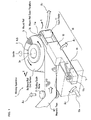
- FIGS. 1 to 6 A tape winding method related to a first embodiment of the present invention will be described, referring to FIGS. 1 to 6.
- an axial direction of a hub 2 is made an up/down direction, one end side thereof (upside shown in FIG.1) is set the upside, the other end side (see FIGS. 3A, 3B, and the like) is set a downside, and magnetic tape MT is assumed to be wound on the hub 2 so that a wound roll end surface 5b at the upside of a wound roll 5 becomes concave.
- a touch roller 11 is also assumed to be same as above.
- a winding apparatus 1 has the hub 2 for winding the magnetic tape MT and the touch roller 11, and is configured by comprising: a wound roll outer surface push means 10 for pushing a wound roll outer periphery 5a (tape surface of an outmost periphery), which is a periphery of the wound roll 5 that consists of the magnetic tape MT, which is wound; a guiding guide roller 21 for guiding the magnetic tape MT to a winding position; and a guiding guide roller movement mechanism (not shown) for moving the guiding guide roller 21.
- a wound roll outer surface push means 10 for pushing a wound roll outer periphery 5a (tape surface of an outmost periphery), which is a periphery of the wound roll 5 that consists of the magnetic tape MT, which is wound
- a guiding guide roller 21 for guiding the magnetic tape MT to a winding position
- a guiding guide roller movement mechanism (not shown) for moving the guiding guide roller 21.
- a hub hole 2a is formed on an axial line of the hub 2, and inner teeth (not shown), which engage a spindle (not shown) of a tape motor unit for rotating the hub 2, are protrudingly provided on an inner periphery of the hub hole 2a.
- the wound roll outer surface push means 10 is configured by comprising: the touch roller 11 for pushing the wound roll outer periphery 5a while rolling thereon; a touch arm 12 (roller support member) for freely rotatably supporting the touch roller 11 by a shaft at one end; a platform 13 for freely rotatably supporting the touch arm 12; a torsion spring 14 (energizing means) provided between the touch arm 12 and the platform 13; a platform rotational movement shaft member 13a, which is penetrated to a predetermined position of the platform 13 and becomes a shaft; and a platform rotational movement mechanism (not shown) for rotationally moving the platform 13 around the platform rotational movement shaft member 13a.
- the touch roller 11 is a member whose figuration is cylindrical and a through hole is formed on a central axial line thereof. In the through hole is inserted a touch roller rotational shaft member 11a.
- the touch roller 11 is formed of an elastic material having a predetermined elasticity. Accordingly, even when the wound roll outer periphery 5a becomes eccentric as the wound roll 5 rotates, the touch roller 11 can preferably follow it and behavior of lateral and radial directions of the magnetic tape MT is designed to be suppressed. Taking the above into consideration, for example, a rubber material such as urethane can be cited as the elastic material of which the touch roller 11 is formed.
- a height position of the touch roller 11 is set so that it can push the wound roll outer periphery 5a with a pressure distribution, which becomes a maximum pressure at the upside (one end side), which is upper than middle in a lateral direction of the magnetic tape MT. That is, by tilting the touch roller 11 for the wound roll outer periphery 5a by means of a rotational movement of the platform 13 as described later, the wound roll outer periphery 5a can be pushed with the pressure distribution, which becomes the maximum pressure at the upside, which is upper than the middle in the lateral direction of the magnetic tape MT.
- a guide roller with a flange may be provided at an upstream side of the touch roller 11.
- the touch roller 11 At one end of the touch arm 12 that forks into two the touch roller rotational shaft member 11a is fixed. And the touch roller 11 is freely rotatably fit on the touch roller rotational shaft member 11a.
- the touch arm 12 is freely rotatably supported by the platform 13 through a touch arm rotational shaft member 12a, which is penetrated to the other end of the touch arm 12 (see an arrow mark A 1 in FIG. 1).
- the torsion spring 14 is provided between the touch arm 12 and the platform 13. And the touch roller 11 is energized in a rotational axial direction of the hub 2 by the torsion spring 14 through the touch arm 12.
- the torsion spring 14 is used, taking a volume and the like into consideration, the present invention is not limited thereto and other elastic members having elasticity, for example, a tension coil spring may be used as needed.
- the torsion spring 14 it is preferable to appropriately change a spring modulus of the torsion spring 14, depending on a width, thickness, and the like of the magnetic tape MT, and to adjust pushing force of the touch roller 11 as needed.
- the platform rotational movement mechanism (not shown) is not specifically limited if it rotationally moves the platform 13 around the platform rotational movement shaft member 13a (see an arrow mark A 2 in FIG. 1), and for example, the platform rotational movement mechanism can be configured by combining a servo motor with a gear mechanism.
- the guiding guide roller 21 is something for guiding the magnetic tape MT and can be used as needed by being selected from a known guide roller with a flange.
- the guiding guide roller movement mechanism (not shown) is not specifically limited if it moves the guiding guide roller 21 to the upside, and for example, the guiding guide roller movement mechanism can be configured by combining a servo motor with a gear mechanism such as a rack and pinion.
- a heating treatment unit 25 is freely settable in temperature and not specifically limited if the wound roll 5 can be heated at a predetermined temperature: For example, a known constant temperature bath is usable. In addition, the heating treatment unit 25 is also preferable to be freely settable in humidity.
- the tape winding method related to the first embodiment comprises a winding process for winding the magnetic tape MT on the hub 2 by the winding apparatus 1 and a heating treatment process for performing a heating treatment for the wound roll 5 by the heating treatment unit 25.
- the magnetic tape MT has generally a non-magnetic base film (support body) and a magnetic layer formed on a base film.
- the magnetic layer is formed by coating a magnetic paint, where a magnetic powder, a bonding agent, an organic solvent, and the like are mixed and adjusted until the magnetic powder is uniformly dispersed on a surface of the base film. Otherwise, the magnetic layer is formed by depositing a ferromagnetic material such as metal and alloy by means of methods such as a vacuum deposition and a sputtering.
- the magnetic powder can be used by being selected as needed, for example, from ferromagnetic ferrite powder such as ⁇ -Fe 2 O 3 , Fe 3 O 4 , and cobalt deposited ⁇ -Fe 2 O 3 ; ferromagnetic chromium dioxide; metal such as Fe, Co, and Ni; ferromagnetic metal powder consisting of alloy containing these; and hexagonal ferrite particulate like a hexagonal plate and the like.
- ferromagnetic ferrite powder such as ⁇ -Fe 2 O 3 , Fe 3 O 4 , and cobalt deposited ⁇ -Fe 2 O 3
- ferromagnetic chromium dioxide ferromagnetic chromium dioxide
- metal such as Fe, Co, and Ni
- ferromagnetic metal powder consisting of alloy containing these
- hexagonal ferrite particulate like like a hexagonal plate and the like.
- the bonding agent can be used polymers such as urethane, vinyl chloride, vinyl acetate, vinyl alcohol, vinylidene chloride, acrylic ester, styrene, butadiene, and acrylic nitrile; copolymers where more than one kind of the polymers is combined; polyester resin; epoxy resin; and the like.
- organic solvent can be used ethers, esters, kinds of ketone, aromatic hydrocarbon, fatty hydrocarbon, and chlorinated hydrocarbon.
- polyesters such as polyethylene terephthalate (PET) and polyethylene naphthalate (PEN); polyolefins such as polypropylene; cellulose derivatives such as nitrocellulose; and polymers such as polyamide, polyvinyl chloride, polycarbonate, and aramid.
- PET polyethylene terephthalate
- PEN polyethylene naphthalate
- polyolefins such as polypropylene
- cellulose derivatives such as nitrocellulose
- polymers such as polyamide, polyvinyl chloride, polycarbonate, and aramid.
- polyesters are low in cost and also excellent in workability and mechanical properties.
- polyethylene naphthalate (PEN) is more excellent in strength, rigidity, and heat resistance than the polyethylene terephthalate (PET).
- PET polyethylene terephthalate
- the aramid is preferable to be added when considering the heat resistance.
- a winding process will be described, making such the magnetic tape MT an object.
- the platform 13 rotationally moves around the platform rotational movement shaft member 13a by the platform rotational movement mechanism (see an arrow mark A 2 in FIG. 1), depending on winding of the magnetic tape MT.
- the touch roller 11 is energized to a center side of the hub 2 by the torsion spring 14, the touch roller 11 is pushed to an outside in a radial direction thereof by the wound roll 5 as the wound roll 5 becomes fatter by the winding. Accordingly, as it becomes fatter by the winding, the touch arm 12 opens outside, making the touch arm rotational movement member 12a an axis (see the arrow mark A 1 in FIG.1).
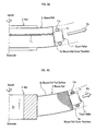
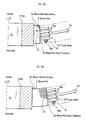
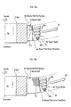
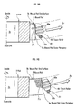
- the touch roller 11 results in moving like an arc (see arrow marks A3 in FIGS. 1, 3A, 3B, 4A, and 4B) to the upside (one end side) of the magnetic tape MT while tilting within an approximate X-X section (section in a radial direction) shown in FIG. 1 as the touch roller 11 recedes from the hub 2 to the outside in the radial direction thereof.
- the wound roll outer periphery 5a results in being pushed by the upside (one end side) of the touch roller 11 with a pressure distribution that becomes a maximum pressure at the upside (one end side), which is upper than middle in the lateral direction of the magnetic tape MT.
- FIGS. 3A and 3B pushing force by the touch roller 11 is schematically shown in F 1 .
- the roller 21 can preferably guide the magnetic tape MT to a winding position with guiding it in the lateral direction thereof.
- the winding can preferably be continued by rotationally moving the platform 13 and moving the guiding guide roller 21.
- wound roll 5 shown in FIG. 5A and 5B can be manufactured.
- the heating treatment unit 25 performs a heating treatment at a predetermined temperature for a predetermined hour.
- set the predetermined temperature at a temperature just under a glass transition temperature of the material of the base film forming the magnetic tape MT.
- the heating treatment is generally called annealing and is performed to heat a polymer molded material, gradually cool it, thereby lessen its strain, and to heat a crystalline polymer to a preferable crystallization temperature and proceed a crystallization.
- a glass transition temperature of the polyethylene terephthalate is 60 to 70 degrees Celsius, preferably set the predetermined temperature at 40 to 69 degrees Celsius and more preferably at 50 to 65 degrees Celsius.
- a glass transition temperature of the polyethylene naphthalate (PEN) is 110 to 120 degrees Celsius, set the predetermined temperature at 40 to 113 degrees Celsius.
- aramid as the material of the base film forming the magnetic tape MT, set the predetermined temperature at 40 to 120 degrees Celsius. Meanwhile, when setting the predetermined temperature at 40 to 120 degrees Celsius, a heating treatment speed can be made faster.
- the material of the base film becomes easy to deform in a short hour, it is preferable to make an inside of the heating treatment unit 25 a predetermined humidity depending on the material of the base film.
- a predetermined humidity depending on the material of the base film.
- PET polyethylene terephthalate
- a shape of the wound roll 5 wound on the hub 2 can be made to be effectively memorized in the magnetic tape MT. That is, a winding way can be given to the magnetic tape MT.
- the predetermined temperature just under the glass transition temperature of the material of the base film, while suppressing an extreme heat shrinkage thereof a residual stress can be reduced with alleviating a non-crystalline portion within the material of the base film, thereby damage becoming difficult to be given to the magnetic tape MT.
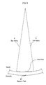
- the tape MT When pulling the magnetic tape MT out of the wound roll 5 where the heating treatment is thus performed, as shown in FIG. 6, the tape MT is wholly constantly curved to the upside of the lateral direction thereof.
- a bow radius R and bow value of the magnetic tape MT is adjusted as predetermined by appropriately setting a concave degree of the wound roll end surface 5b of the wound roll 5.
- the magnetic tape MT When the magnetic tape MT is constantly curved like this, it becomes easy to be regulated in lateral directions thereof during running in a tape drive, thereby a running performance being improved.
- Such the tape winding method related to the first embodiment is, for example, applicable to such a case of winding the magnetic tape MT slit from a web and manufacturing a so called pancake and the like in a manufacturing line of the magnetic tape MT.
- FIGS. 7, 8A, and 8B a tape winding method related to a second embodiment of the present invention will be described, referring to FIGS. 7, 8A, and 8B as needed.
- the tape winding method related to the second embodiment is different in nothing but a winding process, compared to the tape winding method related to the first embodiment.
- the magnetic tape MT is wound and the touch roller 11 is moved like an arc; whereas, in the second embodiment the magnetic tape MT is wound while the hub 2 is moved like an arc for a touch roller 33 at a fixed position.
- a winding apparatus 30 related to the second embodiment has the hub 2, the touch roller 33, a guiding guide roller 22 for guiding the magnetic tape MT to the hub 2 with regulating the tape MT in lateral directions, and a spindle (not shown), and is configured by comprising a spindle movement mechanism, which moves the spindle (not shown) like an arc within an approximate Z-Z section (within a section in a radial direction of the hub 2).
- the touch roller 33 is freely rotatably supported by a touch arm 34 through a touch roller rotational shaft member 33a.
- the touch arm 34 is, for example, fixed at a panel of a tape winder (not shown). Accordingly, the touch roller 33 rotates at a same position.
- the spindle movement mechanism (not shown) is movable like the arc within the approximate Z-Z section (see an arrow mark A 5 in FIG. 7) and comprises an energizing means for energizing the wound roll outer periphery 5a of the wound roll 5 to the touch roller 33.
- the spindle movement mechanism can be configured by combining energizing means such as an arc guide rail (not shown) of a predetermined curvature for guiding a movement of the spindle (not shown), a spring, and a weight.
- a height position of the wound roll 5 is set so that the touch roller 33 can push the wound roll outer periphery 5a with a pressure distribution that becomes a maximum pressure at an upside, which is upper than middle of a lateral direction of the magnetic tape MT.
- the guiding guide roller 22 is usable same as in the first embodiment by being selected from a known guide roller as needed.
- the guiding guide roller movement mechanism (not shown) is provided, in the second embodiment the touch roller 33 rotates at the fixed position, the hub 2 is moved like an arc, and thereby the winding position does not move: Therefore, no guiding guide roller movement mechanism is requested.
- the touch roller 33 results in pushing the wound roll outer periphery 5a by the upside thereof with a pressure, which becomes a maximum pressure at the upside, which is upper than middle in the lateral direction of the magnetic tape MT.
- FIGS. 8A and 8B pushing force by the touch roller 33 is schematically shown in F 2 .
- the magnetic tape MT results in being wound while moving to the upside, and thereby the wound roll 5, where the wound roll end surface 5b of the upside is concave, can be obtained.
- FIGS. 9A and 9B a tape winding method related to a third embodiment of the present invention will be described, referring to FIGS. 9A and 9B.
- the tape winding method related to the third embodiment is different in nothing but a winding process, compared to the tape winding method related to the first embodiment.
- the third embodiment does not use the wound roll outer periphery push means 10 related to the first embodiment, attaches a winding guide 51 having a guide surface 51a to an upside end surface of the hub 2, and moves a guiding guide roller 23 to an upside as the magnetic tape MT is wound so that an upper edge of the magnetic tape MT is wound along the guide surface 51a (see an arrow mark A 7 in FIG. 9A).
- a winding apparatus 50 related to the third embodiment is configured by comprising: the hub 2, the winding guide 51 having the guide surface 51a, the guiding guide roller 23 for guiding the magnetic tape MT to the hub 2 with regulating the tape MT in lateral directions thereof, and a guiding guide roller movement mechanism (not shown) for moving the guiding guide roller 23 to the upside.
- the winding guide 51 has the guide surface 51a, which is convex, to be more precise, for example, taper or partially spherical, for guiding winding of the magnetic tape MT. And the winding guide 51 is fixed by an appropriate means with making the guide surface 51a toward a hub 2 side. Accordingly, when the hub 2 rotates by the spindle (not shown), the hub 2 and the winding guide 51 are designed to integrally rotate.
- the winding apparatus 50 related to the third embodiment does not request the touch roller 11 for pushing the wound roll outer periphery 5a and can be easily configured.
- the wound roll 5 in a state where a wound roll end surface of an upside is along the guide surface 51a can be obtained. That is, the wound roll 5, whose wound roll end surface of the upside is concave, can be obtained.
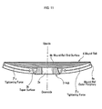
- the tape winding method related to the fourth embodiment is characterized in that a hub shown in FIG. 10 is used instead of the hub 2 used in the first embodiment.
- a hub 3 has a hub hole 3a on an axial line, and furthermore, at an outer periphery of the hub 3 is formed a taper surface 3b, where an upside thereof is a smaller diameter and a downside thereof is a larger diameter.
- a taper angle is set as needed, depending on a concave degree of a wound roll, that is, a bow degree given to the magnetic tape MT.
- the wound roll 6 is concave in a wound roll end surface 6b of an upside thereof same as the wound roll 5.
- tightening force F 3 toward a center side.
- an air accompanying the magnetic tape MT is exhausted by the touch roller 11. Accordingly, an air layer does not almost exist between laps of the magnetic tape MT of the wound roll 6.
- a base film of the magnetic tape MT becomes easy to elastically deform because the downside of the magnetic tape MT configuring the wound roll 6 is larger than the upside thereof in diameter due to the taper. Therefore, in the magnetic tape MT a bow becomes easy to be effectively given.
- the winding object is made the magnetic tape MT
- the present invention is not limited thereto and may be applied to other tape and the like.
- the magnetic tape MT is wound so that the wound roll end surface 5b becomes like the arc in the X-X section
- the section may also be taper (conical) if the wound roll end surface 5b is concave.
- the above is also same for the guide surface 51a of the winding guide 51.
- the heating treatment process is performed in the heating treatment unit 25, otherwise, for example, the heating treatment may also be performed by making the wound roll 5 pass an inside of a continuous furnace kept at an predetermined temperature.
- the wound roll outer periphery 5a is pushed so as not to be damaged by each of the touch rollers 11 and 33 while they roll, each of the touch rollers 11 and 33 is not always requested to roll on the wound roll outer periphery 5a.
- the wound roll outer periphery 5a is pushed by the touch roller 11 according to the elasticity of the torsion spring 14, otherwise, for example, it may also be pushed by forming a touch arm piston portion at the touch arm 12, providing an air cylinder for housing the touch arm piston portion, and pushing with the touch roller 11 through an air pressure within the air cylinder.
- an air pressure within the air cylinder can be monitored and thereby the wound roll outer periphery 5a can be pushed with a same pressure from a start to finish of winding.
- the winding guide 51 and the hub 2 integrally rotate with attaching the winding guide 51 to the hub 2, the winding guide 51 is not always requested to rotate and may also guide the magnetic tape MT while contacting the edge of the magnetic tape MT and the hub 2, which rotate.
- the touch roller 11 is freely rotatably supported by the touch arm 12 at both sides of the touch roller 11, otherwise, for example, it is also available to make a one-side-support configuration as shown in FIG. 12A by using a touch roller 60, which has a plurality of grooves 60a in a peripheral direction, and being freely rotatably supported with the touch arm 61 through a touch roller rotational shaft member 60b at a downside (one side) of the touch roller 60.
- an air which is sucked between a periphery of the touch roller 60 and the wound roll outer periphery 5a, becomes easy to be exhausted from the plurality of the grooves 60a during pushing by the touch roller 60. Accordingly, even when the hub 2 is rotated at a high speed and winding of the magnetic tape MT proceeds (see FIG.12 B), the wound roll outer periphery 5a can be pushed without behavior of the touch roller 60 being disturbed.
- the upside of the wound roll outer periphery 5a becomes easy to be pushed by supporting the touch roller 60 at one side thereof, the downside, with the touch arm 61.
- pushing force by the touch roller 60 is schematically shown in F 4 .
- the wound roll outer periphery 5a becomes easy to be pushed on the upside of the magnetic tape MT, a tape tension distribution occurs, wherein tension becomes higher at the upside in the lateral direction of the magnetic tape MT configuring the wound roll 5 (see FIG. 4A).
- the magnetic tape MT of an outmost periphery becomes easy to move to the upside thereof.
- the wound roll end surface 5b of the upside becomes a concave curved surface with a larger curvature and thereby becomes like a higher concavity. Accordingly, in the magnetic tape MT wound into such the wound roll a larger bow results in being given.
- a touch roller 62 shown in FIGS. 13A and 13B may also be used instead of the touch roller 60 shown in FIGS. 12A and 12B.
- the touch roller 62 On a periphery thereof the touch roller 62 has a taper surface, whose upside becomes a large diameter; on the taper surface a plurality of grooves 62a are formed in a peripheral direction. And the touch roller 62 is freely rotatably supported at one side thereof, the downside, by the touch arm 61 through a touch roller rotational shaft member 62b.
- the wound roll outer periphery 5a becomes easy to be pushed from a nearest position of the upside of the magnetic tape MT.
- a touch roller 63 shown in FIGS. 14A and 14B may also be used instead of the touch roller 60 shown in FIGS. 12A and 12B.
- the touch roller 63 is a figuration of a barrel (also called a crown roller) and on a periphery thereof a plurality of grooves 63a are formed. And the touch roller 63 is freely rotatably supported at one side thereof, the downside, by the touch arm 61 through a touch roller rotational shaft member 63b.
Landscapes
- Winding Of Webs (AREA)
- Manufacturing Of Magnetic Record Carriers (AREA)
Applications Claiming Priority (2)
| Application Number | Priority Date | Filing Date | Title |
|---|---|---|---|
| JP2003284436A JP4074566B2 (ja) | 2003-07-31 | 2003-07-31 | テープの巻き取り方法 |
| JP2003284436 | 2003-07-31 |
Publications (2)
| Publication Number | Publication Date |
|---|---|
| EP1503375A2 true EP1503375A2 (de) | 2005-02-02 |
| EP1503375A3 EP1503375A3 (de) | 2007-09-12 |
Family
ID=33535719
Family Applications (1)
| Application Number | Title | Priority Date | Filing Date |
|---|---|---|---|
| EP04013634A Withdrawn EP1503375A3 (de) | 2003-07-31 | 2004-06-09 | Bandwickelverfahren |
Country Status (4)
| Country | Link |
|---|---|
| US (1) | US20050023722A1 (de) |
| EP (1) | EP1503375A3 (de) |
| JP (1) | JP4074566B2 (de) |
| CN (1) | CN100390864C (de) |
Cited By (1)
| Publication number | Priority date | Publication date | Assignee | Title |
|---|---|---|---|---|
| CN104091688A (zh) * | 2014-06-30 | 2014-10-08 | 中航电测仪器股份有限公司 | 丝绕式应变计绕丝方法及装置 |
Families Citing this family (5)
| Publication number | Priority date | Publication date | Assignee | Title |
|---|---|---|---|---|
| JP4750460B2 (ja) | 2005-04-26 | 2011-08-17 | オリンパス株式会社 | 記録装置の調整方法、記録装置 |
| CN102133950A (zh) * | 2010-10-22 | 2011-07-27 | 苏州市盛百威包装设备有限公司 | 一种用于包装机的收膜装置 |
| CN102366776B (zh) * | 2011-09-28 | 2013-07-17 | 安徽永钰过滤器有限公司 | 过滤器支撑中心管板材送料装置 |
| CN104229515A (zh) * | 2014-09-03 | 2014-12-24 | 德清县传琪装饰材料有限公司 | 木皮收卷自动张紧装置 |
| WO2025062930A1 (ja) * | 2023-09-19 | 2025-03-27 | 富士フイルム株式会社 | 巻取装置 |
Family Cites Families (19)
| Publication number | Priority date | Publication date | Assignee | Title |
|---|---|---|---|---|
| US4141735A (en) * | 1975-03-31 | 1979-02-27 | Eastman Kodak Company | Process for reducing core-set curling tendency and core-set curl of polymeric film elements |
| US4030678A (en) * | 1976-06-18 | 1977-06-21 | Simpson Ralph E | Tape winding device |
| JPS543130U (de) * | 1977-06-10 | 1979-01-10 | ||
| JPS6231645A (ja) * | 1985-07-30 | 1987-02-10 | Fuji Photo Film Co Ltd | 磁気テ−プ巻取り方法および装置 |
| JPS62234286A (ja) * | 1986-04-04 | 1987-10-14 | Fuji Photo Film Co Ltd | 磁気テ−プ巻取方法及び装置 |
| JPH0777070B2 (ja) * | 1988-02-23 | 1995-08-16 | 富士写真フイルム株式会社 | 磁気テープ巻取方法 |
| JP2534101B2 (ja) * | 1988-06-08 | 1996-09-11 | 富士写真フイルム株式会社 | 磁気テ―プ巻取装置 |
| GB2244696B (en) * | 1990-06-08 | 1994-06-08 | Otari Kk | Magnetic tape winding apparatus |
| EP0606070B1 (de) * | 1993-01-04 | 2000-04-12 | Fuji Photo Film Co., Ltd. | Photoapparat mit integriertem Film |
| EP0674218B1 (de) * | 1994-02-25 | 2002-11-13 | Fuji Photo Film Co., Ltd. | Verfahren zur Wärmebehandlung photographischer Polyesterträger |
| JPH08244035A (ja) * | 1995-03-09 | 1996-09-24 | Fuji Photo Film Co Ltd | 帯状高分子フイルムの巻取、アニーリング処理方法、巻戻し方法、及び前記方法による写真感光材料用支持体 |
| JPH09138945A (ja) * | 1995-11-13 | 1997-05-27 | Sony Corp | 磁気テープの製造方法及び磁気テープ |
| ATE296851T1 (de) * | 1996-02-21 | 2005-06-15 | Toray Industries | Verbundfaden und daraus hergestellte faserverstärkte verbundwerkstoffe |
| JPH11259851A (ja) * | 1998-03-12 | 1999-09-24 | Fuji Photo Film Co Ltd | 磁気記録テープ |
| JPH11268706A (ja) * | 1998-03-23 | 1999-10-05 | Naigai Kk | 梱包機のバンド装填装置 |
| DE69832826T2 (de) * | 1998-12-17 | 2006-09-07 | Lots Technology Inc., Sunnyvale | Spule für band mit hoher geschwindigkeit |
| KR100412504B1 (ko) * | 2002-01-17 | 2003-12-31 | 삼성전자주식회사 | 테이프 레코더 주행계의 자기테이프 가이드장치 |
| JP2004280920A (ja) * | 2003-03-14 | 2004-10-07 | Tdk Corp | 磁気テープの製造方法 |
| JP2005228448A (ja) * | 2004-02-16 | 2005-08-25 | Fuji Photo Film Co Ltd | 磁気テープの巻き姿改善処理方法及び磁気テープ |
-
2003
- 2003-07-31 JP JP2003284436A patent/JP4074566B2/ja not_active Expired - Lifetime
-
2004
- 2004-06-09 EP EP04013634A patent/EP1503375A3/de not_active Withdrawn
- 2004-06-21 US US10/871,539 patent/US20050023722A1/en not_active Abandoned
- 2004-08-02 CN CNB2004100588575A patent/CN100390864C/zh not_active Expired - Fee Related
Cited By (2)
| Publication number | Priority date | Publication date | Assignee | Title |
|---|---|---|---|---|
| CN104091688A (zh) * | 2014-06-30 | 2014-10-08 | 中航电测仪器股份有限公司 | 丝绕式应变计绕丝方法及装置 |
| CN104091688B (zh) * | 2014-06-30 | 2016-08-31 | 中航电测仪器股份有限公司 | 丝绕式应变计绕丝方法及装置 |
Also Published As
| Publication number | Publication date |
|---|---|
| CN1581303A (zh) | 2005-02-16 |
| JP2005053617A (ja) | 2005-03-03 |
| EP1503375A3 (de) | 2007-09-12 |
| CN100390864C (zh) | 2008-05-28 |
| JP4074566B2 (ja) | 2008-04-09 |
| US20050023722A1 (en) | 2005-02-03 |
Similar Documents
| Publication | Publication Date | Title |
|---|---|---|
| US7927537B2 (en) | Tape winder and method of processing tape | |
| US20200342902A1 (en) | Magnetic recording medium | |
| JP6645613B1 (ja) | 磁気記録媒体、テープカートリッジ、及びデータ処理方法 | |
| EP1503375A2 (de) | Bandwickelverfahren | |
| US6001446A (en) | Magnetic recording medium | |
| JP2003296918A (ja) | 磁気記録媒体及びその製造方法 | |
| JP2008198262A (ja) | 記録テープカートリッジ | |
| US20050116081A1 (en) | Tape winding method and device, and tape winding body | |
| JP4441395B2 (ja) | テープ処理方法 | |
| US7369363B2 (en) | Method for producing magnetic tape in which a prescribed winding habit is imparted to the magnetic tape | |
| JP2004164808A (ja) | 磁気テープの巻き姿改善処理方法 | |
| US20060115688A1 (en) | Tape-shaped recording medium, and apparatus and method for processing the same | |
| EP1691364A2 (de) | Pasive Bandführung mit Luftlager | |
| JP2629847B2 (ja) | 磁気記録媒体の製造方法 | |
| JPH06168444A (ja) | 磁気記録媒体の製造方法 | |
| JP2004307091A (ja) | 巻取り装置 | |
| JP2005149680A (ja) | テープの巻き取り方法および装置 | |
| JP4135137B2 (ja) | パンケーキ | |
| EP1739660A2 (de) | Herstellungsverfahren für ein bandförmiges Aufzeichnungsmedium | |
| JP2009104713A (ja) | カートリッジ | |
| JP2005317182A (ja) | リーダーテープおよびこれを用いた磁気テープカートリッジ | |
| JPH082760A (ja) | 被走行物の走行状態修正装置 | |
| JP2004164807A (ja) | 磁気テープの巻き姿改善処理方法 | |
| JP2007213726A (ja) | タッチロールを用いた巻き取り装置およびスリット装置 | |
| JPH10265105A (ja) | 細長い帯状の薄いテープ、特に磁気テープのための巻取り補助装置 |
Legal Events
| Date | Code | Title | Description |
|---|---|---|---|
| PUAI | Public reference made under article 153(3) epc to a published international application that has entered the european phase |
Free format text: ORIGINAL CODE: 0009012 |
|
| AK | Designated contracting states |
Kind code of ref document: A2 Designated state(s): AT BE BG CH CY CZ DE DK EE ES FI FR GB GR HU IE IT LI LU MC NL PL PT RO SE SI SK TR |
|
| AX | Request for extension of the european patent |
Extension state: AL HR LT LV MK |
|
| RAP1 | Party data changed (applicant data changed or rights of an application transferred) |
Owner name: FUJIFILM CORPORATION |
|
| PUAL | Search report despatched |
Free format text: ORIGINAL CODE: 0009013 |
|
| AK | Designated contracting states |
Kind code of ref document: A3 Designated state(s): AT BE BG CH CY CZ DE DK EE ES FI FR GB GR HU IE IT LI LU MC NL PL PT RO SE SI SK TR |
|
| AX | Request for extension of the european patent |
Extension state: AL HR LT LV MK |
|
| 17P | Request for examination filed |
Effective date: 20071029 |
|
| AKX | Designation fees paid |
Designated state(s): DE FR GB |
|
| 17Q | First examination report despatched |
Effective date: 20110218 |
|
| STAA | Information on the status of an ep patent application or granted ep patent |
Free format text: STATUS: THE APPLICATION IS DEEMED TO BE WITHDRAWN |
|
| 18D | Application deemed to be withdrawn |
Effective date: 20110629 |