EP1503104B1 - Drehschwingungsdämpfer - Google Patents
Drehschwingungsdämpfer Download PDFInfo
- Publication number
- EP1503104B1 EP1503104B1 EP04016646A EP04016646A EP1503104B1 EP 1503104 B1 EP1503104 B1 EP 1503104B1 EP 04016646 A EP04016646 A EP 04016646A EP 04016646 A EP04016646 A EP 04016646A EP 1503104 B1 EP1503104 B1 EP 1503104B1
- Authority
- EP
- European Patent Office
- Prior art keywords
- sealing membrane
- membrane device
- force
- flywheel according
- flywheel
- Prior art date
- Legal status (The legal status is an assumption and is not a legal conclusion. Google has not performed a legal analysis and makes no representation as to the accuracy of the status listed.)
- Expired - Lifetime
Links
- 239000012528 membrane Substances 0.000 claims abstract description 43
- 238000007789 sealing Methods 0.000 claims abstract description 43
- 230000037431 insertion Effects 0.000 claims 3
- 238000003780 insertion Methods 0.000 claims 3
- 239000006185 dispersion Substances 0.000 claims 1
- 230000005055 memory storage Effects 0.000 claims 1
- 238000009434 installation Methods 0.000 description 8
- 238000004146 energy storage Methods 0.000 description 5
- 230000006835 compression Effects 0.000 description 1
- 238000007906 compression Methods 0.000 description 1
- 230000008878 coupling Effects 0.000 description 1
- 238000010168 coupling process Methods 0.000 description 1
- 238000005859 coupling reaction Methods 0.000 description 1
- 230000000694 effects Effects 0.000 description 1
- 239000002184 metal Substances 0.000 description 1
- 210000002105 tongue Anatomy 0.000 description 1
- 230000007704 transition Effects 0.000 description 1
Images


Classifications
-
- F—MECHANICAL ENGINEERING; LIGHTING; HEATING; WEAPONS; BLASTING
- F16—ENGINEERING ELEMENTS AND UNITS; GENERAL MEASURES FOR PRODUCING AND MAINTAINING EFFECTIVE FUNCTIONING OF MACHINES OR INSTALLATIONS; THERMAL INSULATION IN GENERAL
- F16F—SPRINGS; SHOCK-ABSORBERS; MEANS FOR DAMPING VIBRATION
- F16F15/00—Suppression of vibrations in systems; Means or arrangements for avoiding or reducing out-of-balance forces, e.g. due to motion
- F16F15/10—Suppression of vibrations in rotating systems by making use of members moving with the system
- F16F15/12—Suppression of vibrations in rotating systems by making use of members moving with the system using elastic members or friction-damping members, e.g. between a rotating shaft and a gyratory mass mounted thereon
- F16F15/131—Suppression of vibrations in rotating systems by making use of members moving with the system using elastic members or friction-damping members, e.g. between a rotating shaft and a gyratory mass mounted thereon the rotating system comprising two or more gyratory masses
- F16F15/139—Suppression of vibrations in rotating systems by making use of members moving with the system using elastic members or friction-damping members, e.g. between a rotating shaft and a gyratory mass mounted thereon the rotating system comprising two or more gyratory masses characterised by friction-damping means
-
- F—MECHANICAL ENGINEERING; LIGHTING; HEATING; WEAPONS; BLASTING
- F16—ENGINEERING ELEMENTS AND UNITS; GENERAL MEASURES FOR PRODUCING AND MAINTAINING EFFECTIVE FUNCTIONING OF MACHINES OR INSTALLATIONS; THERMAL INSULATION IN GENERAL
- F16F—SPRINGS; SHOCK-ABSORBERS; MEANS FOR DAMPING VIBRATION
- F16F15/00—Suppression of vibrations in systems; Means or arrangements for avoiding or reducing out-of-balance forces, e.g. due to motion
- F16F15/30—Flywheels
-
- F—MECHANICAL ENGINEERING; LIGHTING; HEATING; WEAPONS; BLASTING
- F16—ENGINEERING ELEMENTS AND UNITS; GENERAL MEASURES FOR PRODUCING AND MAINTAINING EFFECTIVE FUNCTIONING OF MACHINES OR INSTALLATIONS; THERMAL INSULATION IN GENERAL
- F16D—COUPLINGS FOR TRANSMITTING ROTATION; CLUTCHES; BRAKES
- F16D13/00—Friction clutches
- F16D13/58—Details
- F16D13/70—Pressure members, e.g. pressure plates, for clutch-plates or lamellae; Guiding arrangements for pressure members
-
- F—MECHANICAL ENGINEERING; LIGHTING; HEATING; WEAPONS; BLASTING
- F16—ENGINEERING ELEMENTS AND UNITS; GENERAL MEASURES FOR PRODUCING AND MAINTAINING EFFECTIVE FUNCTIONING OF MACHINES OR INSTALLATIONS; THERMAL INSULATION IN GENERAL
- F16F—SPRINGS; SHOCK-ABSORBERS; MEANS FOR DAMPING VIBRATION
- F16F15/00—Suppression of vibrations in systems; Means or arrangements for avoiding or reducing out-of-balance forces, e.g. due to motion
- F16F15/10—Suppression of vibrations in rotating systems by making use of members moving with the system
- F16F15/12—Suppression of vibrations in rotating systems by making use of members moving with the system using elastic members or friction-damping members, e.g. between a rotating shaft and a gyratory mass mounted thereon
-
- F—MECHANICAL ENGINEERING; LIGHTING; HEATING; WEAPONS; BLASTING
- F16—ENGINEERING ELEMENTS AND UNITS; GENERAL MEASURES FOR PRODUCING AND MAINTAINING EFFECTIVE FUNCTIONING OF MACHINES OR INSTALLATIONS; THERMAL INSULATION IN GENERAL
- F16F—SPRINGS; SHOCK-ABSORBERS; MEANS FOR DAMPING VIBRATION
- F16F15/00—Suppression of vibrations in systems; Means or arrangements for avoiding or reducing out-of-balance forces, e.g. due to motion
- F16F15/10—Suppression of vibrations in rotating systems by making use of members moving with the system
- F16F15/12—Suppression of vibrations in rotating systems by making use of members moving with the system using elastic members or friction-damping members, e.g. between a rotating shaft and a gyratory mass mounted thereon
- F16F15/131—Suppression of vibrations in rotating systems by making use of members moving with the system using elastic members or friction-damping members, e.g. between a rotating shaft and a gyratory mass mounted thereon the rotating system comprising two or more gyratory masses
- F16F15/13142—Suppression of vibrations in rotating systems by making use of members moving with the system using elastic members or friction-damping members, e.g. between a rotating shaft and a gyratory mass mounted thereon the rotating system comprising two or more gyratory masses characterised by the method of assembly, production or treatment
-
- F—MECHANICAL ENGINEERING; LIGHTING; HEATING; WEAPONS; BLASTING
- F16—ENGINEERING ELEMENTS AND UNITS; GENERAL MEASURES FOR PRODUCING AND MAINTAINING EFFECTIVE FUNCTIONING OF MACHINES OR INSTALLATIONS; THERMAL INSULATION IN GENERAL
- F16F—SPRINGS; SHOCK-ABSORBERS; MEANS FOR DAMPING VIBRATION
- F16F15/00—Suppression of vibrations in systems; Means or arrangements for avoiding or reducing out-of-balance forces, e.g. due to motion
- F16F15/10—Suppression of vibrations in rotating systems by making use of members moving with the system
- F16F15/16—Suppression of vibrations in rotating systems by making use of members moving with the system using a fluid or pasty material
- F16F15/165—Sealing arrangements
-
- F—MECHANICAL ENGINEERING; LIGHTING; HEATING; WEAPONS; BLASTING
- F16—ENGINEERING ELEMENTS AND UNITS; GENERAL MEASURES FOR PRODUCING AND MAINTAINING EFFECTIVE FUNCTIONING OF MACHINES OR INSTALLATIONS; THERMAL INSULATION IN GENERAL
- F16D—COUPLINGS FOR TRANSMITTING ROTATION; CLUTCHES; BRAKES
- F16D13/00—Friction clutches
- F16D13/58—Details
- F16D13/70—Pressure members, e.g. pressure plates, for clutch-plates or lamellae; Guiding arrangements for pressure members
- F16D2013/703—Pressure members, e.g. pressure plates, for clutch-plates or lamellae; Guiding arrangements for pressure members the pressure plate on the flywheel side is combined with a damper
-
- F—MECHANICAL ENGINEERING; LIGHTING; HEATING; WEAPONS; BLASTING
- F16—ENGINEERING ELEMENTS AND UNITS; GENERAL MEASURES FOR PRODUCING AND MAINTAINING EFFECTIVE FUNCTIONING OF MACHINES OR INSTALLATIONS; THERMAL INSULATION IN GENERAL
- F16F—SPRINGS; SHOCK-ABSORBERS; MEANS FOR DAMPING VIBRATION
- F16F2230/00—Purpose; Design features
- F16F2230/0041—Locking; Fixing in position
Definitions
- the invention relates to a split flywheel, with at least two against the resistance of an energy storage device rotatable relative to each other flywheel masses, between which an elastic sealing membrane device is arranged in a mounting region, which has a spring characteristic resulting from the application of the spring force of the sealing membrane device on the spring travel.
- a split flywheel with such a sealing membrane device is known from FR 2 788 820 A1.
- the object of the invention is therefore to provide a split flywheel, with at least two opposite to the resistance of an energy storage device rotatable flywheel masses between which an elastically strained sealing membrane device is arranged, the tighter or more constant basic hysteresis requirements met as conventional torsional vibration damper.
- the object is in a split flywheel, with at least two against the resistance of an energy storage device rotatable relative to each other flywheels between in which a resilient sealing membrane device is arranged in a mounting region, which has a spring characteristic resulting from the application of the spring force of the sealing membrane device over the spring travel, achieved in that the spring characteristic of the sealing membrane device in the installation area first drops and then increases.
- the sealing membrane device thus has a characteristic such as a plate spring. The spring force can thereby be kept in the installation area within narrower limits than conventional torsional vibration dampers.
- a preferred embodiment of the torsional vibration damper is characterized in that the sealing membrane means, which can also be referred to as a sealing spring means, radially inside a substantially annular disc-shaped inner body, which is connected to the one flywheel, and in that the sealing membrane means radially outwardly a substantially annular disc-shaped Outer body has, which bears against the other flywheel.
- the inner body is preferably integral with the outer body.
- a further preferred embodiment of the torsional vibration damper is characterized in that the outer body, viewed in cross-section, is inclined in the unloaded state relative to the inner body in one direction, and in that the outer body is inclined in the installed state relative to the inner body in the opposite direction , The outer body is thus pressed in the installed state on its flat position, in which it is arranged parallel to the inner body, out in the opposite direction as in the unloaded state.
- a further preferred embodiment of the torsional vibration damper is characterized in that the outer body is provided with a plurality of radial slots, which are formed closed in the radial direction inside and outside. This will be radially inward and outward on the outer body closed force edges created that lead to a stiffening of the outer body.
- a further preferred embodiment of the torsional vibration damper is characterized in that the inner body has a plurality of passage openings and is formed radially inwardly closed.
- the passage openings serve to receive fastening elements with which the inner body is attached to the associated flywheel.
- the closed force edge radially inward leads to a stiffening of the entire sealing membrane device.
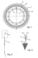
- FIG. 1 shows a sealing membrane device 1 in plan view.
- the sealing membrane device 1 is elastic and is also referred to as a sealing spring device, disc spring membrane or short sealing membrane.
- the sealing membrane device 1 comprises an inner body 3, which has substantially the shape of a circular disk, which is equipped with a plurality of through holes 4, 5.
- the through holes 4, 5 are used for positioning on the sealing membrane device 1 or for attaching the sealing membrane 1 to another component.
- the inner body 3 is integrally connected to an outer body 8, which also has the shape of a circular disk.
- a plurality of slots 9, 10 are formed uniformly distributed over the circumference, which are bounded both radially inwardly and radially outwardly by the outer body 8. The slots 9, 10 are thus closed in the radial direction both outwardly and inwardly.
- the inner body 3 is shown clamped.
- the outer body 8 is shown at 11 in the unloaded state.
- the outer body 8 is shown in its flat position, in which the outer body 8 is arranged parallel to the inner body 3.
- the outer body 8 is shown in the installed state.
- the outer body 8 is in the installed or clamped state 13 from the unloaded state 11 over its flat surface 12 addition also suppressed.
- FIG. 4 shows a torsional vibration damper 20, which comprises a primary flywheel 21 and a secondary flywheel 22.
- the two flywheels 21 and 22, which are also referred to as flywheels, are coupled to one another via a plurality of energy storage elements 24 distributed in the circumferential direction, which are preferably formed by helical compression springs.
- the secondary flywheel 22 is via a flange 25, which is fastened by rivets 26 to the secondary flywheel 22, coupled thereto.
- the sealing membrane device 1 shown in FIGS. 1 to 3 is clamped with its inner body between the flange 25 and the secondary flywheel 22.
- the outer body of the sealing membrane device 1 rests with its outer edge against an extension 27 of the primary flywheel 21.
- the outer body of the sealing membrane device 1 is slightly suppressed in the installed state, so bent from the unloaded state beyond its flatness or angled.
- the secondary flywheel 22 forms the counter-pressure plate of a clutch 28, which comprises a clutch disc 29 with friction linings 30.
- the friction linings 30 are arranged between the counter-pressure plate 22 and a pressure plate 32, which is movable relative to a clutch cover 34 in the axial direction by means of a disc spring device 33 to clamp the friction linings 30 of the clutch disc 29 between the pressure plate 32 and the counter-pressure plate 22.
- the structure and function of a clutch with integrated torsional vibration damper are assumed to be known and therefore not further explained here.
- FIG. 5 shows the spring force F in Newton over the spring travel f in millimeters in the form of a spring characteristic curve of the elastic sealing membrane device 1 illustrated in FIGS. 1 to 4.
- the installation area is designated 37.
- the spring characteristic in the installation area 37 initially drops from a relative maximum 38 to a relative minimum 39 and then increases again.
- the spring characteristic of the sealing membrane device runs in a narrower spring force range than in conventional sealing membrane devices, which generally have a linear spring characteristic.
- the elastic sealing membrane device 1 shown in FIGS. 1 to 4 is preferably formed from sheet metal, which preferably has a thickness of 0.25 to 0.3 Has millimeter.
- the sealing membrane device 1, which is also referred to as a diaphragm spring membrane, has on the outside a closed edge, which is also referred to as the force edge.
- the diaphragm spring diaphragm 1 is also formed closed inside.
- the closed inside force edge causes a stiffening of the entire component, so that the sealing membrane device 1 and the diaphragm spring can be placed much higher and no snap effect occurs.
- the diaphragm spring or sealing membrane device needs no additional support, such as with plate springs with tongues.
- the scattering of the spring force in the spring characteristic shown in Figure 5 is between 70 Newton and 90 Newton and may possibly be adjusted by a change in the altitude.
Landscapes
- Engineering & Computer Science (AREA)
- General Engineering & Computer Science (AREA)
- Mechanical Engineering (AREA)
- Physics & Mathematics (AREA)
- Acoustics & Sound (AREA)
- Aviation & Aerospace Engineering (AREA)
- Manufacturing & Machinery (AREA)
- Mechanical Operated Clutches (AREA)
- Surgical Instruments (AREA)
- Pulleys (AREA)
- Buildings Adapted To Withstand Abnormal External Influences (AREA)
- Steering Controls (AREA)
Description
- Die Erfindung betrifft ein geteiltes Schwungrad, mit wenigstens zwei entgegen dem Widerstand einer Energiespeichereinrichtung relativ zueinander verdrehbaren Schwungmassen, zwischen denen in einem Einbaubereich eine elastische Dichtmembraneinrichtung angeordnet ist, die eine Federkennlinie aufweist, die sich aus der Auftragung der Federkraft der Dichtmembraneinrichtung über dem Federweg ergibt.
- Herkömmliche Drehschwingungsdämpfer bzw. geteilte Schwungräder sind oft mit Dichtmembraneinrichtungen ausgestattet, die eine relativ kurze, linear ansteigende Federkennlinie aufweisen. Dabei kann über den gesamten Einbaubereich eine große Kraftstreuung auftreten. Ein geteiltes Schwungrad mit einer solchen Dichtmembraneinrichtung ist durch die FR 2 788 820 A1 bekannt.
- Aufgabe der Erfindung ist es daher, ein geteiltes Schwungrad, mit wenigstens zwei entgegen dem Widerstand einer Energiespeichereinrichtung relativ zueinander verdrehbaren Schwungmassen, zwischen denen eine elastisch verspannte Dichtmembraneinrichtung angeordnet ist, zu schaffen, der engere bzw. konstantere Grundhysterese-Anforderungen erfüllt als herkömmliche Drehschwingungsdämpfer.
- Die Aufgabe ist bei einem geteilten Schwungrad, mit wenigstens zwei entgegen dem Widerstand einer Energiespeichereinrichtung relativ zueinander verdrehbaren Schwungmassen, zwischen denen in einem Einbaubereich eine elastische Dichtmembraneinrichtung angeordnet ist, die eine Federkennlinie aufweist, die sich aus der Auftragung der Federkraft der Dichtmembraneinrichtung über dem Federweg ergibt, dadurch gelöst, dass die Federkennlinie der Dichtmembraneinrichtung in dem Einbaubereich zunächst abfällt und dann ansteigt. Die Dichtmembraneinrichtung hat also eine Kennlinie wie eine Tellerfeder. Die Federkraft kann dadurch im Einbaubereich in engeren Grenzen gehalten werden als bei herkömmlichen Drehschwingungsdämpfern.
- Ein bevorzugtes Ausführungsbeispiel des Drehschwingungsdämpfers ist dadurch gekennzeichnet, dass die Dichtmembraneinrichtung, die auch als Dichtfedereinrichtung bezeichnet werden kann, radial innen einen im Wesentlichen kreisringscheibenförmigen Innenkörper aufweist, der mit der einen Schwungmasse verbunden ist, und dadurch, dass die Dichtmembraneinrichtung radial außen einen im Wesentlichen kreisringscheibenförmigen Außenkörper aufweist, der an der anderen Schwungmasse anliegt.
Der Innenkörper ist vorzugsweise einstückig mit dem Außenkörper. - Ein weiteres bevorzugtes Ausführungsbeispiel des Drehschwingungsdämpfers ist dadurch gekennzeichnet, dass der Außenkörper, im Querschnitt betrachtet, im unbelasteten Zustand relativ zu dem Innenkörper in eine Richtung geneigt ist, und dadurch, dass der Außenkörper im eingebauten Zustand relativ zu dem Innenkörper in die entgegengesetzte Richtung geneigt ist. Der Außenkörper wird also im eingebauten Zustand über seine Planlage, in der er parallel zu dem Innenkörper angeordnet ist, hinaus in die entgegengesetzte Richtung wie im unbelasteten Zustand gedrückt.
- Ein weiteres bevorzugtes Ausführungsbeispiel des Drehschwingungsdämpfers ist dadurch gekennzeichnet, dass der Außenkörper mit einer Vielzahl radialer Schlitze versehen ist, die in radialer Richtung innen und außen geschlossen ausgebildet sind. Dadurch werden radial innen und außen an dem Außenkörper geschlossene Kraftränder geschaffen, die zu einer Versteifung des Außenkörpers führen.
- Ein weiteres bevorzugtes Ausführungsbeispiel des Drehschwingungsdämpfers ist dadurch gekennzeichnet, dass der Innenkörper mehrere Durchgangöffnungen aufweist und radial innen geschlossen ausgebildet ist. Die Durchgangöffnungen dienen zur Aufnahme von Befestigungselementen, mit denen der Innenkörper an der zugehörigen Schwungmasse befestigt wird. Der geschlossenen Kraftrand radial innen führt zu einer Versteifung der gesamten Dichtmembraneinrichtung.
- Weitere Vorteile, Merkmale und Einzelheiten der Erfindung ergeben sich aus der nachfolgenden Beschreibung, in der unter Bezugnahme auf die Zeichnungen Ausführungsbeispiele im Einzelnen beschrieben sind. Dabei können die in den Ansprüchen und in der Beschreibung erwähnten Merkmale jeweils einzeln für sich oder in beliebiger Kombination erfindungswesentlich sein. Es zeigen:
- Figur 1
- eine Dichtmembraneinrichtung in der Draufsicht;
- Figur 2
- die Dichtmembraneinrichtung aus Figur 1 im Schnitt;
- Figur 3
- einen Ausschnitt aus Figur 2 im belasteten und im unbelasteten Zustand;
- Figur 4
- eine Kupplung mit einem integrierten Drehschwingungsdämpfer und einer Dichtmembraneinrichtung, wie sie in den Figuren 1 bis 3 dargestellt ist;
- Figur 5
- die Federkennlinie der Dichtmembraneinrichtung aus den Figuren 1 bis 3.
- In Figur 1 ist eine Dichtmembraneinrichtung 1 in der Draufsicht dargestellt. Die Dichtmembraneinrichtung 1 ist elastisch ausgebildet und wird auch als Dichtfedereinrichtung, Tellerfedermembran oder kurz Dichtmembran bezeichnet. Die Dichtmembraneinrichtung 1 umfasst einen Innenkörper 3, der im Wesentlichen die Gestalt einer Kreisringscheibe aufweist, die mit mehreren Durchgangslöchern 4, 5 ausgestattet ist. Die Durchgangslöcher 4, 5 dienen zur Positionierung an der Dichtmembraneinrichtung 1 oder zum Befestigen der Dichtmembran 1 an einem anderen Bauteil. Der Innenkörper 3 ist einstückig mit einem Außenkörper 8 verbunden, der ebenfalls die Gestalt einer Kreisringscheibe aufweist. In dem Außenkörper 8 sind über den Umfang gleichmäßig verteilt eine Vielzahl von Schlitzen 9, 10 ausgebildet, die sowohl radial innen als auch radial außen durch den Außenkörper 8 begrenzt sind. Die Schlitze 9, 10 sind also in radialer Richtung sowohl nach außen als auch nach innen geschlossen.
- In Figur 2 sieht man, dass der Außenkörper 8 relativ zu dem Innenkörper 3 abgewinkelt ist. Der Übergang zwischen dem Innenkörper 3 und dem Außenkörper 8 ist, im Querschnitt betrachtet, als gerundete Stufe ausgebildet.
- In Figur 3 ist der Innenkörper 3 eingespannt dargestellt. Der Außenkörper 8 ist bei 11 im entlasteten Zustand dargestellt. Bei 12 ist der Außenkörper 8 in seiner Planlage dargestellt, in der der Außenkörper 8 parallel zu dem Innenkörper 3 angeordnet ist. Bei 13 ist der Außenkörper 8 im eingebauten Zustand dargestellt. Wie man in Figur 3 sieht, ist der Außenkörper 8 im eingebauten beziehungsweise eingespannten Zustand 13 aus dem entlasteten Zustand 11 über seine Planlage 12 hinaus überdrückt.
- In Figur 4 ist ein Drehschwingungsdämpfer 20 dargestellt, der ein primäres Schwungrad 21 und ein sekundäres Schwungrad 22 umfasst. Die beiden Schwungräder 21 und 22, die auch als Schwungmassen bezeichnet werden, sind über mehrere in Umfangsrichtung verteilt angeordnete Energiespeicherelemente 24, die vorzugsweise von Schraubendruckfedern gebildet werden, miteinander gekoppelt. Das sekundäre Schwungrad 22 ist über einen Flansch 25, der durch Nietverbindungen 26 an dem sekundären Schwungrad 22 befestigt ist, mit diesem gekoppelt.
- Die in den Figuren 1 bis 3 dargestellte Dichtmembraneinrichtung 1 ist mit ihrem Innenkörper zwischen dem Flansch 25 und der sekundären Schwungmasse 22 eingespannt. Der Außenkörper der Dichtmembraneinrichtung 1 liegt mit seinem Außenrand an einem Ausläufer 27 der primären Schwungmasse 21 an. Der Außenkörper der Dichtmembraneinrichtung 1 ist im eingebauten Zustand leicht überdrückt, also aus dem entlasteten Zustand über seine Planlage hinaus gebogen beziehungsweise abgewinkelt.
- Die sekundäre Schwungmasse 22 bildet die Gegendruckplatte einer Kupplung 28, die eine Kupplungsscheibe 29 mit Reibbelägen 30 umfasst. Die Reibbeläge 30 sind zwischen der Gegendruckplatte 22 und einer Druckplatte 32 angeordnet, die mit Hilfe einer Tellerfedereinrichtung 33 relativ zu einem Kupplungsdeckel 34 in axialer Richtung bewegbar ist, um die Reibbeläge 30 der Kupplungsscheibe 29 zwischen der Druckplatte 32 und der Gegendruckplatte 22 einzuspannen. Der Aufbau und die Funktion einer Kupplung mit integriertem Drehschwingungsdämpfer werden als bekannt vorausgesetzt und daher hier nicht weiter erläutert.
- In Figur 5 ist die Federkraft F in Newton über dem Federweg f in Millimeter in Form einer Federkennlinie der in den Figuren 1 bis 4 dargestellten elastischen Dichtmembraneinrichtung 1 dargestellt. Der Einbaubereich ist mit 37 bezeichnet. Wie man in Figur 5 sieht, fällt die Federkennlinie im Einbaubereich 37 von einem relativen Maximum 38 zunächst bis zu einem relativen Minimum 39 ab und steigt dann wieder an. Die Federkennlinie der Dichtmembraneinrichtung verläuft in einem engeren Federkraftbereich als bei herkömmlichen Dichtmembraneinrichtungen, die in der Regel eine lineare Federkennlinie aufweisen.
- Die in den Figuren 1 bis 4 dargestellte elastische Dichtmembraneinrichtung 1 ist vorzugsweise aus Blech gebildet, das vorzugsweise eine Dicke von 0,25 bis 0,3 Millimeter aufweist. Die Dichtmembraneinrichtung 1, die auch als Tellerfedermembrane bezeichnet wird, weist außen einen geschlossenen Rand auf, der auch als Kraftrand bezeichnet wird. Die Tellerfedermembrane 1 ist auch innen geschlossen ausgebildet. Der innen geschlossene Kraftrand verursacht eine Versteifung des gesamten Bauteils, so dass die Dichtmembraneinrichtung 1 beziehungsweise die Tellerfeder viel höher aufgestellt werden kann und kein Schnappeffekt auftritt. Die Tellerfeder beziehungsweise Dichtmembraneinrichtung braucht keine zusätzliche Unterstützung, wie zum Beispiel bei Tellerfedern mit Zungen. Die Streuung der Federkraft in der in Figur 5 dargestellten Federkennlinie liegt zwischen 70 Newton und 90 Newton und kann eventuell durch eine Veränderung der Aufstellhöhe angepasst werden.
-
- 1
- Dichtmembraneinrichtung
- 2
- -
- 3
- Innenkörper
- 4
- Durchgangslöcher
- 5
- Durchgangslöcher
- 6
- -
- 7
- -
- 8
- Außenkörper
- 9
- Schlitze
- 10
- Schlitze
- 11
- Außenkörper im entlasteten Zustand
- 12
- Planlage
- 13
- Außenkörper im eingespannten Zustand
- 20
- Drehschwingungsdämpfer
- 21
- Primäres Schwungrad
- 22
- Sekundäres Schwungrad
- 24
- Energiespeicherelemente
- 25
- Flansch
- 26
- Nietverbindungen
- 27
- Ausläufer
- 28
- Kupplung
- 29
- Kupplungsscheibe
- 30
- Reibbeläge
- 31
- -
- 32
- Druckplatte
- 33
- Tellerfedereinrichtung
- 34
- Kupplungsdeckel
- 35
- -
- 36
- -
- 37
- Einbaubereich
- 38
- Relatives Maximum Einbaubereich
- 39
- Relatives Minimum Einbaubereich
Claims (6)
- Geteiltes Schwungrad mit wenigstens zwei entgegen dem Widerstand einer Energiespeichereinrichtung (24) relativ zueinander verdrehbaren Schwungmassen (22, 32), zwischen denen eine elastische Dichtmembraneinrichtung (1) angeordnet ist, dadurch gekennzeichnet, dass die Dichtmembraneinrichtung (1) eine Kraft-Weg-Federkennlinie (Figur 5) aufweist, die nach Erreichen eines Kraftmaximums (38) in einen Einbaubereich (37) übergeht, der eine geringe Kraftstreuung aufweist, und die in dem Einbaubereich (37) zunächst abfällt und dann ansteigt, wodurch die durch die Dichtmembraneinrichtung (1) bei einer Relativverdrehung der Schwungmassen (22, 32) erzeugte Grundhysterese in engeren Grenzen gehalten werden kann.
- Geteiltes Schwungrad nach Anspruch 1, dadurch gekennzeichnet, dass die Federkennlinie der Dichtmembraneinrichtung nach Erreichen eines Kraftmaximums (38) bis zum Erreichen eines Kraftminimums (39) einen abfallenden Einbaubereich (37) aufweist, der in einem engen Federkraftbereich verläuft.
- Schwungrad nach Anspruch 1 oder 2, dadurch gekennzeichnet, dass die Dichtmembraneinrichtung (1) radial innen einen im Wesentlichen kreisringscheibenförmigen Innenkörper (3) aufweist, der mit der einen Schwungmasse (21) verbunden ist, und dadurch, dass die Dichtmembraneinrichtung (1) radial außen einen im Wesentlichen kreisringscheibenförmigen Außenkörper (8) aufweist, der an der anderen Schwungmasse (22) anliegt.
- Schwungrad nach einem der Ansprüche 1 bis 3, dadurch gekennzeichnet, dass der Außenkörper (8), im Querschnitt betrachtet, im unbelasteten Zustand relativ zu dem Innenkörper (3) in eine Richtung (11) geneigt ist, und dadurch, dass der Außenkörper (8) im eingebauten Zustand relativ zu dem Innenkörper in die entgegengesetzte Richtung (13) geneigt ist.
- Schwungrad nach einem der vorhergehenden Ansprüche, dadurch gekennzeichnet, dass der Außenkörper (8) mit einer Vielzahl radialer Schlitze (9, 10) versehen ist, die in radialer Richtung innen und außen geschlossen ausgebildet sind.
- Schwungrad nach einem der vorhergehenden Ansprüche, dadurch gekennzeichnet, dass der Innenkörper (3) mehrere Durchgangsöffnungen (4, 5) aufweist und radial innen geschlossen ausgebildet ist.
Priority Applications (1)
| Application Number | Priority Date | Filing Date | Title |
|---|---|---|---|
| EP06004972A EP1666764B1 (de) | 2003-07-28 | 2004-07-15 | Drehschwingungsdämpfer |
Applications Claiming Priority (2)
| Application Number | Priority Date | Filing Date | Title |
|---|---|---|---|
| DE10334314 | 2003-07-28 | ||
| DE10334314 | 2003-07-28 |
Related Child Applications (1)
| Application Number | Title | Priority Date | Filing Date |
|---|---|---|---|
| EP06004972A Division EP1666764B1 (de) | 2003-07-28 | 2004-07-15 | Drehschwingungsdämpfer |
Publications (3)
| Publication Number | Publication Date |
|---|---|
| EP1503104A2 EP1503104A2 (de) | 2005-02-02 |
| EP1503104A3 EP1503104A3 (de) | 2005-02-16 |
| EP1503104B1 true EP1503104B1 (de) | 2006-11-29 |
Family
ID=33521432
Family Applications (2)
| Application Number | Title | Priority Date | Filing Date |
|---|---|---|---|
| EP06004972A Expired - Lifetime EP1666764B1 (de) | 2003-07-28 | 2004-07-15 | Drehschwingungsdämpfer |
| EP04016646A Expired - Lifetime EP1503104B1 (de) | 2003-07-28 | 2004-07-15 | Drehschwingungsdämpfer |
Family Applications Before (1)
| Application Number | Title | Priority Date | Filing Date |
|---|---|---|---|
| EP06004972A Expired - Lifetime EP1666764B1 (de) | 2003-07-28 | 2004-07-15 | Drehschwingungsdämpfer |
Country Status (6)
| Country | Link |
|---|---|
| EP (2) | EP1666764B1 (de) |
| KR (2) | KR101181956B1 (de) |
| CN (1) | CN100419292C (de) |
| AT (2) | ATE532987T1 (de) |
| BR (1) | BRPI0402781B1 (de) |
| DE (2) | DE502004002148D1 (de) |
Cited By (2)
| Publication number | Priority date | Publication date | Assignee | Title |
|---|---|---|---|---|
| DE102008043663A1 (de) | 2008-11-12 | 2010-05-20 | Zf Friedrichshafen Ag | Torsionsschwingungsdämpfer, insbesondere für den Antriebsstrang eines Fahrzeugs |
| DE102008054560A1 (de) | 2008-12-12 | 2010-06-17 | Zf Friedrichshafen Ag | Drehmomentübertragungseinheit, insbesondere für den Antriebsstrang eines Fahrzeugs |
Families Citing this family (17)
| Publication number | Priority date | Publication date | Assignee | Title |
|---|---|---|---|---|
| CN101223380B (zh) * | 2005-07-14 | 2012-01-11 | 舍弗勒技术两合公司 | 减振装置、尤其是双质量飞轮 |
| JP2009500581A (ja) * | 2005-07-14 | 2009-01-08 | ルーク ラメレン ウント クツプルングスバウ ベタイリグングス コマンディートゲゼルシャフト | 振動減衰装置、特にデュアルマスフライホイール |
| WO2008128562A1 (de) † | 2007-04-23 | 2008-10-30 | Wirtgen Gmbh | SELBSTFAHRENDE STRAßENBAUMASCHINE |
| CN102356251B (zh) * | 2009-04-27 | 2014-12-10 | 舍弗勒技术股份两合公司 | 振动阻尼器 |
| CN102893055B (zh) * | 2010-05-07 | 2014-11-26 | Zf腓特烈斯哈芬股份公司 | 扭矩传递组件及具有该扭矩传递组件的传动系统 |
| DE112011102213B4 (de) | 2010-06-29 | 2022-01-20 | Schaeffler Technologies AG & Co. KG | Kupplungsaggregat und Verfahren zur Montage eines Kupplungsaggregats |
| ITTO20120263A1 (it) * | 2012-03-22 | 2013-09-23 | Dayco Europe Srl | Volano a doppia massa e molla a spirale con configurazione in parallelo |
| JP5734365B2 (ja) | 2013-06-04 | 2015-06-17 | 株式会社エクセディ | トルクコンバータのロックアップ装置 |
| JP5685304B2 (ja) * | 2013-06-04 | 2015-03-18 | 株式会社エクセディ | トルクコンバータのロックアップ装置 |
| JP5878893B2 (ja) | 2013-07-11 | 2016-03-08 | 株式会社エクセディ | トルクコンバータのロックアップ装置 |
| DE112015000991A5 (de) * | 2014-02-26 | 2016-12-15 | Schaeffler Technologies AG & Co. KG | Gegendruckplatte für eine Kupplung |
| DE102015225239A1 (de) | 2015-12-15 | 2017-06-22 | Schaeffler Technologies AG & Co. KG | Drehschwingungsdämpfer |
| CN106481731B (zh) * | 2016-09-29 | 2019-11-19 | 珠海华粤传动科技有限公司 | 一种圆弧弹簧减震器 |
| DE102017121804A1 (de) * | 2016-10-07 | 2018-04-12 | Schaeffler Technologies AG & Co. KG | Unterzusammenbau für ein Zweimassenschwungrad, Wuchtanlage und Verfahren zum Wuchten eines Unterzusammenbaus |
| DE102019110681B4 (de) * | 2019-04-25 | 2025-09-25 | Schaeffler Technologies AG & Co. KG | Drehmomentübertragungseinrichtung, Hybridischer Antriebsstrang mit dieser und Elektromaschine für diesen |
| DE102020127381A1 (de) * | 2020-10-16 | 2022-04-21 | Sram Deutschland Gmbh | Freilaufnabe mit Feder aus Kunststoff mit zelliger Struktur |
| CN116379107B (zh) * | 2023-04-07 | 2025-09-19 | 华东交通大学 | 一种弯扭复合减振器 |
Family Cites Families (12)
| Publication number | Priority date | Publication date | Assignee | Title |
|---|---|---|---|---|
| DE8509183U1 (de) * | 1985-03-27 | 1985-07-04 | Fichtel & Sachs Ag, 8720 Schweinfurt | Kupplungsgehäusebefestigung über Sprengring |
| GB2217429B (en) * | 1988-03-26 | 1991-12-18 | Luk Lamellen & Kupplungsbau | Apparatus for damping vibrations |
| US5146811A (en) * | 1990-12-24 | 1992-09-15 | Luk Lamellen Und Kupplungsbau Gmbh | Vibration damping apparatus |
| DE4311102C2 (de) * | 1993-04-03 | 2002-06-20 | Zf Sachs Ag | Schwungrad mit reduziertem Außendurchmesser |
| FR2715204B1 (fr) * | 1994-01-18 | 1996-03-01 | Valeo | Double volant amortisseur, notamment pour véhicule automobile. |
| JP3805803B2 (ja) * | 1994-02-08 | 2006-08-09 | 株式会社エクセディ | 動力伝達装置 |
| FR2786240B1 (fr) * | 1998-11-19 | 2001-02-09 | Valeo | Amortisseur de torsion, notamment double volant amortisseur, pour vehicule automobile |
| DE10002259B4 (de) * | 1999-01-25 | 2019-03-28 | Schaeffler Technologies AG & Co. KG | Drehmomentübertragungseinrichtung |
| JP2001020973A (ja) | 1999-07-08 | 2001-01-23 | Exedy Corp | ツインダンパーディスク組立体及びそれを使用したツインクラッチ |
| FR2801356B1 (fr) * | 1999-11-23 | 2002-02-08 | Valeo | Dispositif a volant d'inertie, en particulier pour embrayage |
| DE10004125A1 (de) * | 2000-01-31 | 2001-08-02 | Mannesmann Sachs Ag | Torsionsschwingungsdämpfer |
| JP5076205B2 (ja) * | 2001-01-19 | 2012-11-21 | シェフラー テクノロジーズ アクチエンゲゼルシャフト ウント コンパニー コマンディートゲゼルシャフト | ねじり振動減衰器 |
-
2004
- 2004-07-15 EP EP06004972A patent/EP1666764B1/de not_active Expired - Lifetime
- 2004-07-15 DE DE502004002148T patent/DE502004002148D1/de not_active Expired - Lifetime
- 2004-07-15 AT AT06004972T patent/ATE532987T1/de active
- 2004-07-15 AT AT04016646T patent/ATE347059T1/de not_active IP Right Cessation
- 2004-07-15 DE DE102004034087A patent/DE102004034087A1/de not_active Withdrawn
- 2004-07-15 EP EP04016646A patent/EP1503104B1/de not_active Expired - Lifetime
- 2004-07-16 BR BRPI0402781A patent/BRPI0402781B1/pt not_active IP Right Cessation
- 2004-07-21 KR KR1020040056709A patent/KR101181956B1/ko not_active Expired - Fee Related
- 2004-07-28 CN CNB2004100587055A patent/CN100419292C/zh not_active Expired - Fee Related
-
2011
- 2011-07-22 KR KR1020110073012A patent/KR101230805B1/ko not_active Expired - Fee Related
Cited By (3)
| Publication number | Priority date | Publication date | Assignee | Title |
|---|---|---|---|---|
| DE102008043663A1 (de) | 2008-11-12 | 2010-05-20 | Zf Friedrichshafen Ag | Torsionsschwingungsdämpfer, insbesondere für den Antriebsstrang eines Fahrzeugs |
| DE102008043663B4 (de) | 2008-11-12 | 2022-01-27 | Zf Friedrichshafen Ag | Torsionsschwingungsdämpfer, insbesondere für den Antriebsstrang eines Fahrzeugs |
| DE102008054560A1 (de) | 2008-12-12 | 2010-06-17 | Zf Friedrichshafen Ag | Drehmomentübertragungseinheit, insbesondere für den Antriebsstrang eines Fahrzeugs |
Also Published As
| Publication number | Publication date |
|---|---|
| DE102004034087A1 (de) | 2005-02-17 |
| KR20050013494A (ko) | 2005-02-04 |
| BRPI0402781A (pt) | 2005-06-07 |
| BRPI0402781B1 (pt) | 2016-05-24 |
| KR101230805B1 (ko) | 2013-02-06 |
| ATE347059T1 (de) | 2006-12-15 |
| KR101181956B1 (ko) | 2012-09-12 |
| CN100419292C (zh) | 2008-09-17 |
| EP1666764A3 (de) | 2006-09-06 |
| EP1503104A2 (de) | 2005-02-02 |
| KR20110091493A (ko) | 2011-08-11 |
| EP1503104A3 (de) | 2005-02-16 |
| EP1666764A2 (de) | 2006-06-07 |
| EP1666764B1 (de) | 2011-11-09 |
| CN1576627A (zh) | 2005-02-09 |
| DE502004002148D1 (de) | 2007-01-11 |
| ATE532987T1 (de) | 2011-11-15 |
Similar Documents
| Publication | Publication Date | Title |
|---|---|---|
| DE69634788T2 (de) | Dämpfungsscheibeneinheit mit einem Reibungsmechanismus mit verbesserten Reibungselementen | |
| DE3405949C2 (de) | ||
| EP1666764B1 (de) | Drehschwingungsdämpfer | |
| DE102016223413A1 (de) | Zweimassenschwungrad mit Reibsteuerscheibe | |
| DE19881886B4 (de) | Reibungskupplung | |
| DE9212203U1 (de) | Kupplungsscheibe mit radial elastischem Kunststoffring | |
| DE102008043211A1 (de) | Torsionsschwingungsdämpferanordnung, insbesondere für den Antriebsstrang eines Fahrzeugs | |
| DE69507091T2 (de) | Drehmoment-absorbierende Scheibe | |
| DE2702201A1 (de) | Reibkupplungsdeckelanordnung | |
| EP3111102B1 (de) | Kupplungsvorrichtung | |
| EP2795148A1 (de) | Reibungskupplung | |
| DE3538444C2 (de) | ||
| DE102011087066A1 (de) | Selbstnachstellende Kupplung | |
| DE102012213105A1 (de) | Drehmomentübertragungseinrichtung | |
| DE102004034086B4 (de) | Drehschwingungsdämpfer | |
| DE102014213924A1 (de) | Lagereinrichtung für ein Kupplungssystem eines Kraftfahrzeugs | |
| DE69503721T3 (de) | Drehschwingungsdämpfer, insbesondere für Kraftfahrzeuge | |
| DE102021106477B4 (de) | Drehschwingungsdämpfer | |
| DE19514817A1 (de) | Reibungskupplung für ein Kraftfahrzeug | |
| WO2017076407A1 (de) | Fliehkraftpendeleinrichtung, drehmomentübertragungseinrichtung und verfahren zum montieren und auswuchten einer fliehkraftpendeleinrichtung | |
| DE102018123388A1 (de) | Drehschwingungsdämpfer | |
| DE102015102980B4 (de) | Ausrückmechanismus für eine Reibungskupplung | |
| DE102018124840A1 (de) | Zweimassenschwungrad mit Reibeinrichtung | |
| DE19949362A1 (de) | Torsionsschwingungsdämpfer | |
| DE29724494U1 (de) | Reibungskupplung mit Vordämpfer |
Legal Events
| Date | Code | Title | Description |
|---|---|---|---|
| PUAI | Public reference made under article 153(3) epc to a published international application that has entered the european phase |
Free format text: ORIGINAL CODE: 0009012 |
|
| PUAL | Search report despatched |
Free format text: ORIGINAL CODE: 0009013 |
|
| AK | Designated contracting states |
Kind code of ref document: A2 Designated state(s): AT BE BG CH CY CZ DE DK EE ES FI FR GB GR HU IE IT LI LU MC NL PL PT RO SE SI SK TR |
|
| AX | Request for extension of the european patent |
Extension state: AL HR LT LV MK |
|
| AK | Designated contracting states |
Kind code of ref document: A3 Designated state(s): AT BE BG CH CY CZ DE DK EE ES FI FR GB GR HU IE IT LI LU MC NL PL PT RO SE SI SK TR |
|
| AX | Request for extension of the european patent |
Extension state: AL HR LT LV MK |
|
| 17P | Request for examination filed |
Effective date: 20050816 |
|
| AKX | Designation fees paid |
Designated state(s): AT BE BG CH CY CZ DE DK EE ES FI FR GB GR HU IE IT LI LU MC NL PL PT RO SE SI SK TR |
|
| GRAP | Despatch of communication of intention to grant a patent |
Free format text: ORIGINAL CODE: EPIDOSNIGR1 |
|
| GRAS | Grant fee paid |
Free format text: ORIGINAL CODE: EPIDOSNIGR3 |
|
| GRAA | (expected) grant |
Free format text: ORIGINAL CODE: 0009210 |
|
| AK | Designated contracting states |
Kind code of ref document: B1 Designated state(s): AT BE BG CH CY CZ DE DK EE ES FI FR GB GR HU IE IT LI LU MC NL PL PT RO SE SI SK TR |
|
| PG25 | Lapsed in a contracting state [announced via postgrant information from national office to epo] |
Ref country code: SI Free format text: LAPSE BECAUSE OF FAILURE TO SUBMIT A TRANSLATION OF THE DESCRIPTION OR TO PAY THE FEE WITHIN THE PRESCRIBED TIME-LIMIT Effective date: 20061129 Ref country code: FI Free format text: LAPSE BECAUSE OF FAILURE TO SUBMIT A TRANSLATION OF THE DESCRIPTION OR TO PAY THE FEE WITHIN THE PRESCRIBED TIME-LIMIT Effective date: 20061129 Ref country code: NL Free format text: LAPSE BECAUSE OF FAILURE TO SUBMIT A TRANSLATION OF THE DESCRIPTION OR TO PAY THE FEE WITHIN THE PRESCRIBED TIME-LIMIT Effective date: 20061129 Ref country code: IE Free format text: LAPSE BECAUSE OF FAILURE TO SUBMIT A TRANSLATION OF THE DESCRIPTION OR TO PAY THE FEE WITHIN THE PRESCRIBED TIME-LIMIT Effective date: 20061129 Ref country code: RO Free format text: LAPSE BECAUSE OF FAILURE TO SUBMIT A TRANSLATION OF THE DESCRIPTION OR TO PAY THE FEE WITHIN THE PRESCRIBED TIME-LIMIT Effective date: 20061129 Ref country code: PL Free format text: LAPSE BECAUSE OF FAILURE TO SUBMIT A TRANSLATION OF THE DESCRIPTION OR TO PAY THE FEE WITHIN THE PRESCRIBED TIME-LIMIT Effective date: 20061129 Ref country code: CZ Free format text: LAPSE BECAUSE OF FAILURE TO SUBMIT A TRANSLATION OF THE DESCRIPTION OR TO PAY THE FEE WITHIN THE PRESCRIBED TIME-LIMIT Effective date: 20061129 Ref country code: SK Free format text: LAPSE BECAUSE OF FAILURE TO SUBMIT A TRANSLATION OF THE DESCRIPTION OR TO PAY THE FEE WITHIN THE PRESCRIBED TIME-LIMIT Effective date: 20061129 |
|
| REG | Reference to a national code |
Ref country code: GB Ref legal event code: FG4D Free format text: NOT ENGLISH |
|
| REG | Reference to a national code |
Ref country code: CH Ref legal event code: EP |
|
| REG | Reference to a national code |
Ref country code: IE Ref legal event code: FG4D Free format text: LANGUAGE OF EP DOCUMENT: GERMAN |
|
| REF | Corresponds to: |
Ref document number: 502004002148 Country of ref document: DE Date of ref document: 20070111 Kind code of ref document: P |
|
| PG25 | Lapsed in a contracting state [announced via postgrant information from national office to epo] |
Ref country code: BG Free format text: LAPSE BECAUSE OF FAILURE TO SUBMIT A TRANSLATION OF THE DESCRIPTION OR TO PAY THE FEE WITHIN THE PRESCRIBED TIME-LIMIT Effective date: 20070228 Ref country code: DK Free format text: LAPSE BECAUSE OF FAILURE TO SUBMIT A TRANSLATION OF THE DESCRIPTION OR TO PAY THE FEE WITHIN THE PRESCRIBED TIME-LIMIT Effective date: 20070228 Ref country code: SE Free format text: LAPSE BECAUSE OF FAILURE TO SUBMIT A TRANSLATION OF THE DESCRIPTION OR TO PAY THE FEE WITHIN THE PRESCRIBED TIME-LIMIT Effective date: 20070228 |
|
| PG25 | Lapsed in a contracting state [announced via postgrant information from national office to epo] |
Ref country code: ES Free format text: LAPSE BECAUSE OF FAILURE TO SUBMIT A TRANSLATION OF THE DESCRIPTION OR TO PAY THE FEE WITHIN THE PRESCRIBED TIME-LIMIT Effective date: 20070312 |
|
| PG25 | Lapsed in a contracting state [announced via postgrant information from national office to epo] |
Ref country code: PT Free format text: LAPSE BECAUSE OF FAILURE TO SUBMIT A TRANSLATION OF THE DESCRIPTION OR TO PAY THE FEE WITHIN THE PRESCRIBED TIME-LIMIT Effective date: 20070430 |
|
| ET | Fr: translation filed | ||
| NLV1 | Nl: lapsed or annulled due to failure to fulfill the requirements of art. 29p and 29m of the patents act | ||
| GBV | Gb: ep patent (uk) treated as always having been void in accordance with gb section 77(7)/1977 [no translation filed] |
Effective date: 20061129 |
|
| REG | Reference to a national code |
Ref country code: IE Ref legal event code: FD4D |
|
| PLBE | No opposition filed within time limit |
Free format text: ORIGINAL CODE: 0009261 |
|
| STAA | Information on the status of an ep patent application or granted ep patent |
Free format text: STATUS: NO OPPOSITION FILED WITHIN TIME LIMIT |
|
| 26N | No opposition filed |
Effective date: 20070830 |
|
| PG25 | Lapsed in a contracting state [announced via postgrant information from national office to epo] |
Ref country code: GB Free format text: LAPSE BECAUSE OF FAILURE TO SUBMIT A TRANSLATION OF THE DESCRIPTION OR TO PAY THE FEE WITHIN THE PRESCRIBED TIME-LIMIT Effective date: 20061129 |
|
| BERE | Be: lapsed |
Owner name: LUK LAMELLEN UND KUPPLUNGSBAU BETEILIGUNGS K.G. Effective date: 20070731 |
|
| PG25 | Lapsed in a contracting state [announced via postgrant information from national office to epo] |
Ref country code: GR Free format text: LAPSE BECAUSE OF FAILURE TO SUBMIT A TRANSLATION OF THE DESCRIPTION OR TO PAY THE FEE WITHIN THE PRESCRIBED TIME-LIMIT Effective date: 20070301 Ref country code: MC Free format text: LAPSE BECAUSE OF NON-PAYMENT OF DUE FEES Effective date: 20070731 |
|
| PG25 | Lapsed in a contracting state [announced via postgrant information from national office to epo] |
Ref country code: BE Free format text: LAPSE BECAUSE OF NON-PAYMENT OF DUE FEES Effective date: 20070731 |
|
| PG25 | Lapsed in a contracting state [announced via postgrant information from national office to epo] |
Ref country code: AT Free format text: LAPSE BECAUSE OF NON-PAYMENT OF DUE FEES Effective date: 20070715 |
|
| PGFP | Annual fee paid to national office [announced via postgrant information from national office to epo] |
Ref country code: IT Payment date: 20080721 Year of fee payment: 5 |
|
| PG25 | Lapsed in a contracting state [announced via postgrant information from national office to epo] |
Ref country code: EE Free format text: LAPSE BECAUSE OF FAILURE TO SUBMIT A TRANSLATION OF THE DESCRIPTION OR TO PAY THE FEE WITHIN THE PRESCRIBED TIME-LIMIT Effective date: 20061129 |
|
| REG | Reference to a national code |
Ref country code: CH Ref legal event code: PL |
|
| PG25 | Lapsed in a contracting state [announced via postgrant information from national office to epo] |
Ref country code: CH Free format text: LAPSE BECAUSE OF NON-PAYMENT OF DUE FEES Effective date: 20080731 Ref country code: LI Free format text: LAPSE BECAUSE OF NON-PAYMENT OF DUE FEES Effective date: 20080731 |
|
| PG25 | Lapsed in a contracting state [announced via postgrant information from national office to epo] |
Ref country code: LU Free format text: LAPSE BECAUSE OF NON-PAYMENT OF DUE FEES Effective date: 20070715 Ref country code: CY Free format text: LAPSE BECAUSE OF FAILURE TO SUBMIT A TRANSLATION OF THE DESCRIPTION OR TO PAY THE FEE WITHIN THE PRESCRIBED TIME-LIMIT Effective date: 20061129 |
|
| PG25 | Lapsed in a contracting state [announced via postgrant information from national office to epo] |
Ref country code: HU Free format text: LAPSE BECAUSE OF FAILURE TO SUBMIT A TRANSLATION OF THE DESCRIPTION OR TO PAY THE FEE WITHIN THE PRESCRIBED TIME-LIMIT Effective date: 20070530 Ref country code: TR Free format text: LAPSE BECAUSE OF FAILURE TO SUBMIT A TRANSLATION OF THE DESCRIPTION OR TO PAY THE FEE WITHIN THE PRESCRIBED TIME-LIMIT Effective date: 20061129 |
|
| PG25 | Lapsed in a contracting state [announced via postgrant information from national office to epo] |
Ref country code: IT Free format text: LAPSE BECAUSE OF NON-PAYMENT OF DUE FEES Effective date: 20090715 |
|
| REG | Reference to a national code |
Ref country code: DE Ref legal event code: R081 Ref document number: 502004002148 Country of ref document: DE Owner name: SCHAEFFLER TECHNOLOGIES AG & CO. KG, DE Free format text: FORMER OWNER: SCHAEFFLER TECHNOLOGIES GMBH & CO. KG, 91074 HERZOGENAURACH, DE Effective date: 20120828 Ref country code: DE Ref legal event code: R081 Ref document number: 502004002148 Country of ref document: DE Owner name: SCHAEFFLER TECHNOLOGIES GMBH & CO. KG, DE Free format text: FORMER OWNER: SCHAEFFLER TECHNOLOGIES GMBH & CO. KG, 91074 HERZOGENAURACH, DE Effective date: 20120828 |
|
| REG | Reference to a national code |
Ref country code: FR Ref legal event code: TP Owner name: SCHAEFFLER TECHNOLOGIES AG & CO. KG, DE Effective date: 20130408 |
|
| REG | Reference to a national code |
Ref country code: DE Ref legal event code: R081 Ref document number: 502004002148 Country of ref document: DE Owner name: SCHAEFFLER TECHNOLOGIES GMBH & CO. KG, DE Free format text: FORMER OWNER: SCHAEFFLER TECHNOLOGIES AG & CO. KG, 91074 HERZOGENAURACH, DE Effective date: 20140213 Ref country code: DE Ref legal event code: R081 Ref document number: 502004002148 Country of ref document: DE Owner name: SCHAEFFLER TECHNOLOGIES AG & CO. KG, DE Free format text: FORMER OWNER: SCHAEFFLER TECHNOLOGIES AG & CO. KG, 91074 HERZOGENAURACH, DE Effective date: 20140213 |
|
| REG | Reference to a national code |
Ref country code: DE Ref legal event code: R081 Ref document number: 502004002148 Country of ref document: DE Owner name: SCHAEFFLER TECHNOLOGIES AG & CO. KG, DE Free format text: FORMER OWNER: SCHAEFFLER TECHNOLOGIES GMBH & CO. KG, 91074 HERZOGENAURACH, DE Effective date: 20150126 |
|
| REG | Reference to a national code |
Ref country code: FR Ref legal event code: PLFP Year of fee payment: 13 |
|
| REG | Reference to a national code |
Ref country code: FR Ref legal event code: PLFP Year of fee payment: 14 |
|
| REG | Reference to a national code |
Ref country code: FR Ref legal event code: PLFP Year of fee payment: 15 |
|
| PGFP | Annual fee paid to national office [announced via postgrant information from national office to epo] |
Ref country code: DE Payment date: 20220920 Year of fee payment: 19 |
|
| PGFP | Annual fee paid to national office [announced via postgrant information from national office to epo] |
Ref country code: FR Payment date: 20220720 Year of fee payment: 19 |
|
| P01 | Opt-out of the competence of the unified patent court (upc) registered |
Effective date: 20230523 |
|
| REG | Reference to a national code |
Ref country code: DE Ref legal event code: R119 Ref document number: 502004002148 Country of ref document: DE |
|
| PG25 | Lapsed in a contracting state [announced via postgrant information from national office to epo] |
Ref country code: DE Free format text: LAPSE BECAUSE OF NON-PAYMENT OF DUE FEES Effective date: 20240201 |
|
| PG25 | Lapsed in a contracting state [announced via postgrant information from national office to epo] |
Ref country code: FR Free format text: LAPSE BECAUSE OF NON-PAYMENT OF DUE FEES Effective date: 20230731 |