EP1500873B1 - Dispositif d'éclairage - Google Patents
Dispositif d'éclairage Download PDFInfo
- Publication number
- EP1500873B1 EP1500873B1 EP04015703A EP04015703A EP1500873B1 EP 1500873 B1 EP1500873 B1 EP 1500873B1 EP 04015703 A EP04015703 A EP 04015703A EP 04015703 A EP04015703 A EP 04015703A EP 1500873 B1 EP1500873 B1 EP 1500873B1
- Authority
- EP
- European Patent Office
- Prior art keywords
- fastening
- reflector
- holder
- lighting assembly
- assembly according
- Prior art date
- Legal status (The legal status is an assumption and is not a legal conclusion. Google has not performed a legal analysis and makes no representation as to the accuracy of the status listed.)
- Expired - Lifetime
Links
- 239000011521 glass Substances 0.000 claims 1
- 239000006059 cover glass Substances 0.000 description 2
- 230000002349 favourable effect Effects 0.000 description 2
- 238000004519 manufacturing process Methods 0.000 description 2
- 238000007789 sealing Methods 0.000 description 2
- 229910000639 Spring steel Inorganic materials 0.000 description 1
- 230000000994 depressogenic effect Effects 0.000 description 1
- 230000000694 effects Effects 0.000 description 1
- 238000009957 hemming Methods 0.000 description 1
- 238000005286 illumination Methods 0.000 description 1
- 238000000465 moulding Methods 0.000 description 1
- 238000000926 separation method Methods 0.000 description 1
- 239000000725 suspension Substances 0.000 description 1
- 230000007704 transition Effects 0.000 description 1
Images

Classifications
-
- F—MECHANICAL ENGINEERING; LIGHTING; HEATING; WEAPONS; BLASTING
- F21—LIGHTING
- F21S—NON-PORTABLE LIGHTING DEVICES; SYSTEMS THEREOF; VEHICLE LIGHTING DEVICES SPECIALLY ADAPTED FOR VEHICLE EXTERIORS
- F21S43/00—Signalling devices specially adapted for vehicle exteriors, e.g. brake lamps, direction indicator lights or reversing lights
- F21S43/10—Signalling devices specially adapted for vehicle exteriors, e.g. brake lamps, direction indicator lights or reversing lights characterised by the light source
- F21S43/19—Attachment of light sources or lamp holders
-
- F—MECHANICAL ENGINEERING; LIGHTING; HEATING; WEAPONS; BLASTING
- F21—LIGHTING
- F21S—NON-PORTABLE LIGHTING DEVICES; SYSTEMS THEREOF; VEHICLE LIGHTING DEVICES SPECIALLY ADAPTED FOR VEHICLE EXTERIORS
- F21S41/00—Illuminating devices specially adapted for vehicle exteriors, e.g. headlamps
- F21S41/10—Illuminating devices specially adapted for vehicle exteriors, e.g. headlamps characterised by the light source
- F21S41/19—Attachment of light sources or lamp holders
- F21S41/196—Wire spring attachments
Definitions
- the present invention relates to a lighting device, in particular for motor vehicles, according to the preamble of claim 1.
- An illumination device of the aforementioned type is already known from DE 1 031 744.
- a lighting device with a reflector and a lamp inserted in the reflector neck is disclosed.
- To attach the bulb is provided that two over the reflector neck tensioned coil springs secure the form-fitting inserted bulbs against falling out.
- DE 34 32 445 discloses a U-shaped clamping element made of spring steel, which is rotatably mounted at its closed end to a reflector and the free ends caused by the application of a resistance caused by the clamping force of the spring element in corresponding recesses of the reflector can be hung in such a way thereby the middle part applies a holding force on the socket against the reflector neck.
- a lighting device with the characterizing features of claim 1.
- the locking mechanism comprises at least one drawbar and a clamping bracket, wherein the clamping bracket is pivotally mounted on the reflector neck and is connected via lever arms with the clamping yoke, wherein the clamping bracket is suitable by depression to exert a closing force on the frame over the clamping yoke, a lighting device is provided which can be handled in an advantageous manner, since a separation between the actual operating element, the clamping bracket, and the closing element, the drawbar takes place.
- a much higher closure force can be generated by the existing lever arm or the length of the tension bow, resulting in a secure and sealing connection between socket and reflector neck.
- the drawbar is a wire bow with a U-shaped configuration.
- This embodiment is simple to manufacture and has sufficient elasticity to optionally additionally build up a closure force by elongation or to compensate for manufacturing tolerances.
- the clamping bow is a wire bow with a U-shaped configuration, wherein end of a Switzerlandbügelability is provided for pivotally receiving the drawbar, which also end lever arms are mounted in the extend substantially vertically from the clamping bracket.
- a favorable lever arm arrangement is provided, which is for operation the drawbar is ideally suited.
- the lever arm, deviating from a vertical position can be easily employed, so that the clamping yoke transitions in a horizontal position of the tension bracket in a favorable locking position, in which although no maximum pressure force is applied, the clamping bracket is prevented from hemming.
- a seal between the reflector neck and the socket is provided.
- the sealing effect between socket and reflector neck is thereby supported, on the other hand, the seal acts as a spring, so that here additional contact forces can be provided.
- the reflector is equipped with a clamping receptacle for fastening the tension bow.
- the clamp receptacle serves to hold the tension bow in a position in which the tension bow exerts a defined locking force on the mount. Due to the arrangement of clamping bracket, clamping bracket and lever arm results in a position of the tension bracket, in which a maximum locking force is exerted on the socket.
- the clamping receptacle is arranged such that the receiving point for the clamping bracket is arranged in the actuating direction behind this aforementioned position, so that there is a latching of the locking mechanism.
- the reflector neck is provided with a cam which can engage in a corresponding recess of the socket. This ensures that the socket and thus the lighting means in a predetermined position in the reflector area is introduced, so that, for example, a pre-tuned light beam path can be ensured.
- the socket is equipped with a stop which is adapted to receive the drawbar.
- the clamping yoke is held in a predetermined position, advantageously in the middle of the socket, so that the pressure forces can be optimally distributed over the socket.
- the stop is a box-shaped molding of the socket, wherein the stop is equipped on the inside with contacts for the electrical supply of the lamp.
- the stop is equally used as a covering for the contacts, which, among other things space is saved.
- the reflector on the opposite side of the reflector neck with a cover glass air and is sealed watertight.
- This arrangement results in a total of a lighting device which can be closed air-tight and waterproof all around, so that there is a broad field of application.
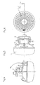
- a lighting device 1 essentially comprises a light-emitting means 12 with a socket 2, wherein the socket 2 is suitable for connection to a reflector neck 4 of a reflector 17 and can be held by a clamping yoke 6.
- the reflector 17 is essentially a hemispherical shell, the inside with a reflective Surface is equipped and head end is equipped with the cylindrical reflector neck 4. At the other open end of the reflector, a translucent cover glass 11 is provided, which is preferably air-tight and waterproof connected to the reflector 17. Furthermore, the reflector is equipped on the outside with various functional elements, such as mounting eyelets 18, a leaf spring 16 and a clamping receptacle 14 for an even closer to described clamping bracket 8.
- the reflector neck 4 serves, as already shown above, for receiving the holder 2.
- the holder 2 in turn represents the holder for the lamp 12 and is equipped for electrical supply with contacts 13.
- the socket 2 has a recess at a defined location, in which a cam 5 of the reflector neck 4 can engage, whereby the socket 2 can be used only in a certain position in the reflector neck 4.
- an annular seal 3 is provided between the socket 2 and the reflector neck 4, which is suitable for contributing to an airtight and watertight connection between the aforementioned elements.
- the lighting device 1 is equipped with a locking mechanism, which consists essentially of a clamping yoke 6 and a clamping bracket 8.
- the clamping bracket 8 is essentially a U-shaped bracket, which consists at the open end with a Switzerlandbügelability 10 and two perpendicular to the U-shaped portion arranged lever arms 15, wherein the lever arms 15 are accommodated end in a pivot bearing 9, which is located at the upper end of the reflector neck 4.
- the clamping bracket 8 is thus pivotally mounted on the reflector neck 4, but can be mounted in a clamp receptacle 14.
- the drawbar 6 is also a U-shaped bracket which is pivotally mounted on the Switzerlandbügelability 10 and the socket 2 can project beyond the head.
- the version 2 is further equipped with a stop 7, to which the clamping yoke 6 can be applied.
Landscapes
- Engineering & Computer Science (AREA)
- General Engineering & Computer Science (AREA)
- Non-Portable Lighting Devices Or Systems Thereof (AREA)
- Arrangement Of Elements, Cooling, Sealing, Or The Like Of Lighting Devices (AREA)
Claims (9)
- Dispositif d'éclairage en particulier pour véhicules, comportant- un réflecteur (17) avec un col de réflecteur (4), dans lequel- le col de réflecteur (4) est approprié pour recevoir un support (2), dans lequel- le support (2) est approprié pour recevoir une source de lumière (12) et- un mécanisme de fermeture est prévu, qui est approprié pour la fixation du support (2) dans le col de réflecteur (4),caractérisé en ce que
le mécanisme de fermeture comprend au moins deux étriers distincts, notamment un étrier de traction (6) et un étrier de tension (8), dans lequel l'étrier de tension (8) est disposé oscillant dans le col de réflecteur (4) et est relié à l'étrier de traction (6) par l'intermédiaire des bras de levier (15), où l'étrier de tension (8) est amené par de basses pressions à exercer une force de fermeture sur le support (2) par l'intermédiaire de l'étrier de traction (6). - Dispositif d'éclairage selon la revendication 1, caractérisé en ce que, concernant l'étrier de traction (6), il s'agit d'un étrier en fils en forme de U.
- Dispositif d'éclairage selon la revendication 1 ou 2, caractérisé en ce que, en ce qui concerne l'étrier de tension (8), il s'agit d'un étrier en fils en forme de U, dans lequel à son extrémité est prévu un logement pour l'étrier de traction (10) pour le support oscillante de l'étrier de traction (6), dans lequel également à son extrémité, des bras de levier (15) sont prévus, qui s'étendent sensiblement verticalement depuis l'étrier de tension (8).
- Dispositif d'éclairage selon l'une des revendications 1 à 3, caractérisé en ce qu'un joint est prévu entre le col de réflecteur (4) et le support (2).
- Dispositif d'éclairage selon l'une des revendications 1 à 4, caractérisé en ce que le réflecteur (17) est muni d'une réception par serrage (14) pour la fixation de l'étrier de tension (8).
- Dispositif d'éclairage selon l'une des revendications 1 à 5, caractérisé en ce que le col de réflecteur (4) est muni d'une came (5), qui peut pénétrer dans un évidement correspondant du support.
- Dispositif d'éclairage selon l'une des revendications 1 à 6, caractérisé en ce que le support (2) est muni d'une butée (7), qui est appropriée pour recevoir l'étrier de traction (6).
- Dispositif d'éclairage selon l'une des revendications 1 à 7, caractérisé en ce que, en ce qui concerne la butée (7), il s'agit d'une formation en forme de boîtier du support (2), où la butée (7) est munie intérieurement de contacts (13) en vue de l'alimentation électrique de la source de lumière (12).
- Dispositif d'éclairage selon l'une des revendications 1 à 8, caractérisé en ce que le réflecteur (17) est fermé de façon étanche à l'air et à l'eau par un verre de protection (11) sur le côté opposé du col de réflecteur (4).
Applications Claiming Priority (2)
| Application Number | Priority Date | Filing Date | Title |
|---|---|---|---|
| DE10333036 | 2003-07-21 | ||
| DE10333036A DE10333036A1 (de) | 2003-07-21 | 2003-07-21 | Beleuchtungseinrichtung |
Publications (3)
| Publication Number | Publication Date |
|---|---|
| EP1500873A2 EP1500873A2 (fr) | 2005-01-26 |
| EP1500873A3 EP1500873A3 (fr) | 2005-02-02 |
| EP1500873B1 true EP1500873B1 (fr) | 2007-03-07 |
Family
ID=33482988
Family Applications (1)
| Application Number | Title | Priority Date | Filing Date |
|---|---|---|---|
| EP04015703A Expired - Lifetime EP1500873B1 (fr) | 2003-07-21 | 2004-07-03 | Dispositif d'éclairage |
Country Status (3)
| Country | Link |
|---|---|
| EP (1) | EP1500873B1 (fr) |
| DE (2) | DE10333036A1 (fr) |
| ES (1) | ES2283908T3 (fr) |
Families Citing this family (2)
| Publication number | Priority date | Publication date | Assignee | Title |
|---|---|---|---|---|
| DE102006017165A1 (de) * | 2006-04-12 | 2007-10-18 | Hella Kgaa Hueck & Co. | Scheinwerfer für Fahrzeuge |
| DE102012011596B3 (de) | 2012-06-13 | 2013-07-04 | Decoma (Germany) Gmbh | Aufnahmevorrichtung |
Family Cites Families (7)
| Publication number | Priority date | Publication date | Assignee | Title |
|---|---|---|---|---|
| GB813619A (en) * | 1956-07-05 | 1959-05-21 | Machal Projecteurs | Means for removably fixing a lamp in a reflector |
| DE1031744B (de) | 1957-05-16 | 1958-06-12 | Westfaelische Metall Industrie | Befestigungsanordnung der Gluehlampenfassung bei Kraftfahrzeug-Reflektoren |
| DE3432445A1 (de) * | 1984-09-04 | 1986-03-13 | Robert Bosch Gmbh, 7000 Stuttgart | Scheinwerfer fuer kraftfahrzeuge |
| FR2626062B1 (fr) * | 1988-01-15 | 1990-05-04 | Cibie Projecteurs | Systeme de verrouillage et de deverrouillage d'une lampe sur un porte-lampe, plus particulierement pour un dispositif d'eclairage ou de signalisation notamment de vehicule automobile |
| DE4406111A1 (de) * | 1994-02-25 | 1995-08-31 | Bosch Gmbh Robert | Befestigung einer Lichtquelle in einer Aufnahme eines Scheinwerfers |
| JP3428343B2 (ja) * | 1997-01-24 | 2003-07-22 | 市光工業株式会社 | 車両用灯具 |
| DE19756456A1 (de) * | 1997-12-18 | 1999-06-24 | Hella Kg Hueck & Co | Fassungseinrichtung für eine Lampe eines Fahrzeugscheinwerfers |
-
2003
- 2003-07-21 DE DE10333036A patent/DE10333036A1/de not_active Withdrawn
-
2004
- 2004-07-03 ES ES04015703T patent/ES2283908T3/es not_active Expired - Lifetime
- 2004-07-03 DE DE502004003107T patent/DE502004003107D1/de not_active Expired - Lifetime
- 2004-07-03 EP EP04015703A patent/EP1500873B1/fr not_active Expired - Lifetime
Also Published As
| Publication number | Publication date |
|---|---|
| EP1500873A2 (fr) | 2005-01-26 |
| ES2283908T3 (es) | 2007-11-01 |
| DE10333036A1 (de) | 2005-02-10 |
| DE502004003107D1 (de) | 2007-04-19 |
| EP1500873A3 (fr) | 2005-02-02 |
Similar Documents
| Publication | Publication Date | Title |
|---|---|---|
| DE69009290T2 (de) | Lampenfassung mit niedrigem Profil und deren Herstellungsverfahren. | |
| DE69408494T2 (de) | Scheinwerfer für Kraftfahrzeuge | |
| DE112012002266B4 (de) | Außengriffvorrichtung der Fahrzeugtür | |
| DE4331884A1 (de) | Abdeckeinrichtung | |
| EP1776543B1 (fr) | Mecanisme de verrouillage pour dispositifs d'eclairage | |
| DE202016104291U1 (de) | Schutzvorrichtung, insbesondere Zelt oder Markise, sowie Verbindungsvorrichtung hierfür | |
| EP3405997A1 (fr) | Connecteur électrique enfichable et procédé de montage de celui-ci | |
| EP1500873B1 (fr) | Dispositif d'éclairage | |
| EP0429922B1 (fr) | Phare du type projecteur | |
| DE69103593T2 (de) | Schnellkupplungseinrichtung für Batterieendklemme. | |
| DE202011002216U1 (de) | Leuchtengehäuse | |
| DE10215020B3 (de) | Elektrischer Wippenschalter | |
| DE4408590B4 (de) | Elektrische Vorrichtung mit Anschlußklemme und Zeiger | |
| DE10123826A1 (de) | Türaußengriff für die Fahrzeugtür eines Kraftfahrzeuges | |
| DE10053723A1 (de) | Kraftfahrzeugscheinwerfer mit Mitteln zur Einstellung der Reflektorausrichtung und Mitteln für einen vereinfachten Lampenaustausch | |
| EP1009012A1 (fr) | Lampe électrique | |
| DE10303329A1 (de) | Lampenfassung für einen Kraftfahrzeugscheinwerfer und zur Aufnahme einer solchen Lampenfassung vorgesehener Scheinwerferreflektor | |
| DE3833316A1 (de) | Verbesserungen in der struktur von kraftfahrzeuglampen | |
| WO2018158325A1 (fr) | Dispositif d'éclairage comportant une tête lumineuse montée rotative | |
| EP1116254B1 (fr) | Lampe electrique | |
| DE8801347U1 (de) | Elektrischer Schmelzsicherungsschalter | |
| DE10022235B4 (de) | Schaltvorrichtung für eine Blendenanordnung | |
| EP0705731B1 (fr) | Feu de véhicule en particulier pour plaque d'immatriculation | |
| DE19949907A1 (de) | Heckleuchte für ein Fahrzeug | |
| DE10035528B4 (de) | Leuchte, insbesondere Leseleuchte für Fahrzeuge |
Legal Events
| Date | Code | Title | Description |
|---|---|---|---|
| PUAI | Public reference made under article 153(3) epc to a published international application that has entered the european phase |
Free format text: ORIGINAL CODE: 0009012 |
|
| PUAL | Search report despatched |
Free format text: ORIGINAL CODE: 0009013 |
|
| AK | Designated contracting states |
Kind code of ref document: A2 Designated state(s): AT BE BG CH CY CZ DE DK EE ES FI FR GB GR HU IE IT LI LU MC NL PL PT RO SE SI SK TR |
|
| AX | Request for extension of the european patent |
Extension state: AL HR LT LV MK |
|
| AK | Designated contracting states |
Kind code of ref document: A3 Designated state(s): AT BE BG CH CY CZ DE DK EE ES FI FR GB GR HU IE IT LI LU MC NL PL PT RO SE SI SK TR |
|
| AX | Request for extension of the european patent |
Extension state: AL HR LT LV MK |
|
| 17P | Request for examination filed |
Effective date: 20050716 |
|
| AKX | Designation fees paid |
Designated state(s): DE ES FR GB IT |
|
| GRAP | Despatch of communication of intention to grant a patent |
Free format text: ORIGINAL CODE: EPIDOSNIGR1 |
|
| GRAS | Grant fee paid |
Free format text: ORIGINAL CODE: EPIDOSNIGR3 |
|
| GRAA | (expected) grant |
Free format text: ORIGINAL CODE: 0009210 |
|
| AK | Designated contracting states |
Kind code of ref document: B1 Designated state(s): DE ES FR GB IT |
|
| REG | Reference to a national code |
Ref country code: GB Ref legal event code: FG4D Free format text: NOT ENGLISH |
|
| REF | Corresponds to: |
Ref document number: 502004003107 Country of ref document: DE Date of ref document: 20070419 Kind code of ref document: P |
|
| GBT | Gb: translation of ep patent filed (gb section 77(6)(a)/1977) |
Effective date: 20070427 |
|
| ET | Fr: translation filed | ||
| REG | Reference to a national code |
Ref country code: ES Ref legal event code: FG2A Ref document number: 2283908 Country of ref document: ES Kind code of ref document: T3 |
|
| PLBE | No opposition filed within time limit |
Free format text: ORIGINAL CODE: 0009261 |
|
| STAA | Information on the status of an ep patent application or granted ep patent |
Free format text: STATUS: NO OPPOSITION FILED WITHIN TIME LIMIT |
|
| 26N | No opposition filed |
Effective date: 20071210 |
|
| PGFP | Annual fee paid to national office [announced via postgrant information from national office to epo] |
Ref country code: ES Payment date: 20090812 Year of fee payment: 6 Ref country code: FR Payment date: 20090710 Year of fee payment: 6 |
|
| PGFP | Annual fee paid to national office [announced via postgrant information from national office to epo] |
Ref country code: GB Payment date: 20090701 Year of fee payment: 6 |
|
| PGFP | Annual fee paid to national office [announced via postgrant information from national office to epo] |
Ref country code: IT Payment date: 20090720 Year of fee payment: 6 |
|
| GBPC | Gb: european patent ceased through non-payment of renewal fee |
Effective date: 20100703 |
|
| REG | Reference to a national code |
Ref country code: FR Ref legal event code: ST Effective date: 20110331 |
|
| PG25 | Lapsed in a contracting state [announced via postgrant information from national office to epo] |
Ref country code: IT Free format text: LAPSE BECAUSE OF NON-PAYMENT OF DUE FEES Effective date: 20100703 Ref country code: FR Free format text: LAPSE BECAUSE OF NON-PAYMENT OF DUE FEES Effective date: 20100802 |
|
| PG25 | Lapsed in a contracting state [announced via postgrant information from national office to epo] |
Ref country code: GB Free format text: LAPSE BECAUSE OF NON-PAYMENT OF DUE FEES Effective date: 20100703 |
|
| REG | Reference to a national code |
Ref country code: ES Ref legal event code: FD2A Effective date: 20110818 |
|
| PG25 | Lapsed in a contracting state [announced via postgrant information from national office to epo] |
Ref country code: ES Free format text: LAPSE BECAUSE OF NON-PAYMENT OF DUE FEES Effective date: 20100704 |
|
| REG | Reference to a national code |
Ref country code: DE Ref legal event code: R081 Ref document number: 502004003107 Country of ref document: DE Owner name: HELLA GMBH & CO. KGAA, DE Free format text: FORMER OWNER: HELLA KGAA HUECK & CO., 59557 LIPPSTADT, DE |
|
| REG | Reference to a national code |
Ref country code: DE Ref legal event code: R084 Ref document number: 502004003107 Country of ref document: DE |
|
| PGFP | Annual fee paid to national office [announced via postgrant information from national office to epo] |
Ref country code: DE Payment date: 20220608 Year of fee payment: 19 |
|
| REG | Reference to a national code |
Ref country code: DE Ref legal event code: R119 Ref document number: 502004003107 Country of ref document: DE |
|
| PG25 | Lapsed in a contracting state [announced via postgrant information from national office to epo] |
Ref country code: DE Free format text: LAPSE BECAUSE OF NON-PAYMENT OF DUE FEES Effective date: 20240201 |