EP1500873A2 - Dispositif d'éclairage - Google Patents
Dispositif d'éclairage Download PDFInfo
- Publication number
- EP1500873A2 EP1500873A2 EP04015703A EP04015703A EP1500873A2 EP 1500873 A2 EP1500873 A2 EP 1500873A2 EP 04015703 A EP04015703 A EP 04015703A EP 04015703 A EP04015703 A EP 04015703A EP 1500873 A2 EP1500873 A2 EP 1500873A2
- Authority
- EP
- European Patent Office
- Prior art keywords
- lighting device
- reflector
- socket
- reflector neck
- clamping
- Prior art date
- Legal status (The legal status is an assumption and is not a legal conclusion. Google has not performed a legal analysis and makes no representation as to the accuracy of the status listed.)
- Granted
Links
Images

Classifications
-
- F—MECHANICAL ENGINEERING; LIGHTING; HEATING; WEAPONS; BLASTING
- F21—LIGHTING
- F21S—NON-PORTABLE LIGHTING DEVICES; SYSTEMS THEREOF; VEHICLE LIGHTING DEVICES SPECIALLY ADAPTED FOR VEHICLE EXTERIORS
- F21S43/00—Signalling devices specially adapted for vehicle exteriors, e.g. brake lamps, direction indicator lights or reversing lights
- F21S43/10—Signalling devices specially adapted for vehicle exteriors, e.g. brake lamps, direction indicator lights or reversing lights characterised by the light source
- F21S43/19—Attachment of light sources or lamp holders
-
- F—MECHANICAL ENGINEERING; LIGHTING; HEATING; WEAPONS; BLASTING
- F21—LIGHTING
- F21S—NON-PORTABLE LIGHTING DEVICES; SYSTEMS THEREOF; VEHICLE LIGHTING DEVICES SPECIALLY ADAPTED FOR VEHICLE EXTERIORS
- F21S41/00—Illuminating devices specially adapted for vehicle exteriors, e.g. headlamps
- F21S41/10—Illuminating devices specially adapted for vehicle exteriors, e.g. headlamps characterised by the light source
- F21S41/19—Attachment of light sources or lamp holders
- F21S41/196—Wire spring attachments
Definitions
- the present invention relates to a lighting device in particular for motor vehicles according to the preamble of Claim 1.
- to Fixing the bulb is provided that two over the reflector neck tensioned coil springs the form-fitting Secure the inserted bulbs from falling out.
- a Lighting device with the characterizing features of Claim 1 solved. Because of the locking mechanism comprises at least one drawbar and a clamping bracket, wherein the clamping bracket is pivotally mounted on the reflector neck and is connected via lever arms with the clamping yoke, wherein the Clamp by depressing it is suitable over the Pulling bracket to exert a locking force on the socket is a lighting device provided in Advantageously manageable, since a separation between the actual operating element, the clamping bracket, and the closing element, the drawbar, takes place. About that In addition, by the existing lever arm or the length of Clamping a significantly higher locking force generated which gives a safe and sealing connection between frame and reflector neck results.
- the present invention provides that it is in the Clamp around a wire hanger with a U-shaped shape is, with the end a Switzerlandbügelability to swivel Recording of the drawbar is provided, also end lever arms are mounted, which are essentially extend vertically from the clamping bracket.
- This will be a convenient lever arm arrangement provided for the operation the drawbar is ideally suited.
- the Lever arm slightly different from a vertical position be employed, so that the drawbar in a horizontal position of the tension bracket goes into a favorable locking position, in which, although no maximum pressure force is applied, the However, clamping bracket is prevented from handling.
- the reflector with a clamping receptacle for fixing the tension bracket Is provided.
- the clamping receptacle essentially serves to hold the clamp in a position in which the Clamp a defined locking force on the socket exercises. Due to the arrangement of clamp, drawbar and lever arm results in a position of the tension bracket, in the a maximum closing force is exerted on the socket.
- the clamping receptacle is arranged such that the pickup point for the clamp in Actuation direction behind this aforementioned position is arranged, so that a self-holding of the Closing mechanism results.
- Invention may be provided that the reflector neck with a cam is provided, which in a corresponding Recess of the socket can intervene. This will Make sure that the socket and thus the bulb in a predetermined position in the reflector region is introduced, so that, for example, a vorgereimmter Light beam can be ensured.
- the socket is equipped with a stop that to is suitable to take the drawbar. This will be the Drawbar in a predetermined position, advantageously in the middle held on the socket, so that the pressure forces can be optimally distributed over the socket.
- Invention is envisaged that it is at the stop to a box-shaped shape of the socket is, wherein the Inside stop with contacts for electrical supply of the bulb is equipped. This will be the stop equally used as a cladding for the contacts, which among other things space is saved.
- the Reflector on the opposite side of the reflector neck with a cover glass air and water tight. This arrangement results in a total of Lighting device the all-round air and waterproof can be closed, so that a wide Field of application results.
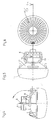
- a lighting device 1 comprises in essentially a lamp 12 with a socket 2, wherein the Version 2 for connection to a reflector neck 4 of a Reflector 17 is suitable and held over a clamping yoke 6 can be.
- the reflector 17 is essentially a Hemispherical shell, the inside with a reflective Surface is equipped and head end with the cylindrical reflector neck 4 is equipped. To the other open end of the reflector is a translucent Cover glass 11 is provided, which preferably air and waterproof is connected to the reflector 17. Furthermore is the reflector on the outside with various functional elements, such as mounting lugs 18, a leaf spring 16 and a terminal receptacle 14 for a later to be described clamping bracket. 8 fitted.
- the reflector neck 4 serves, as already shown above, for Recording of the version 2.
- the version 2 again represents the Holder for the bulb 12 is and is for electrical Supply of contacts 13 equipped.
- an annular Seal 3 between the socket 2 and the reflector neck. 4 provided, which is suitable to an air and waterproof connection between the aforementioned elements contribute.
- the lighting device 1 is provided with a Locking mechanism equipped essentially a yoke 6 and a clamping bracket 8 consists.
- Clamp 8 is essentially a U-shaped Hanger, which at the open end with a Switzerlandbügelability 10 and two arranged perpendicular to the U-shaped portion Lever arms 15 is made, the lever arms 15 end in a pivot bearing 9 are received, which is at the upper end the reflector neck 4 is located.
- the clamping bracket 8 is thus pivotally mounted on the reflector neck 4, but can in a terminal receiving 14 are attached.
- the drawbar 6 is also a U-shaped Bracket pivotally attached to the Switzerlandbügelability 10 is attached and the socket 2 can project beyond the head.
- the Version 2 is also equipped with a stop 7 at the tie bar 6 can be created.
- a Locking mechanism for fixing the socket 2 in the Reflector neck 4 can serve by the drawbar 6 to the Brought stop 7 and the clamping bracket 8 is depressed until the clamping bar end engages in the clamping receptacle 14.
- the drawbar 6 By a suitable selection of the Hebelarmin presses the drawbar. 6 on the version 2, so that a predeterminable contact pressure an air and watertight connection between the socket 2 and the reflector neck 4 can generate.
Landscapes
- Engineering & Computer Science (AREA)
- General Engineering & Computer Science (AREA)
- Non-Portable Lighting Devices Or Systems Thereof (AREA)
- Arrangement Of Elements, Cooling, Sealing, Or The Like Of Lighting Devices (AREA)
Applications Claiming Priority (2)
| Application Number | Priority Date | Filing Date | Title |
|---|---|---|---|
| DE10333036 | 2003-07-21 | ||
| DE10333036A DE10333036A1 (de) | 2003-07-21 | 2003-07-21 | Beleuchtungseinrichtung |
Publications (3)
| Publication Number | Publication Date |
|---|---|
| EP1500873A2 true EP1500873A2 (fr) | 2005-01-26 |
| EP1500873A3 EP1500873A3 (fr) | 2005-02-02 |
| EP1500873B1 EP1500873B1 (fr) | 2007-03-07 |
Family
ID=33482988
Family Applications (1)
| Application Number | Title | Priority Date | Filing Date |
|---|---|---|---|
| EP04015703A Expired - Lifetime EP1500873B1 (fr) | 2003-07-21 | 2004-07-03 | Dispositif d'éclairage |
Country Status (3)
| Country | Link |
|---|---|
| EP (1) | EP1500873B1 (fr) |
| DE (2) | DE10333036A1 (fr) |
| ES (1) | ES2283908T3 (fr) |
Families Citing this family (2)
| Publication number | Priority date | Publication date | Assignee | Title |
|---|---|---|---|---|
| DE102006017165A1 (de) * | 2006-04-12 | 2007-10-18 | Hella Kgaa Hueck & Co. | Scheinwerfer für Fahrzeuge |
| DE102012011596B3 (de) | 2012-06-13 | 2013-07-04 | Decoma (Germany) Gmbh | Aufnahmevorrichtung |
Citations (1)
| Publication number | Priority date | Publication date | Assignee | Title |
|---|---|---|---|---|
| DE1031744B (de) | 1957-05-16 | 1958-06-12 | Westfaelische Metall Industrie | Befestigungsanordnung der Gluehlampenfassung bei Kraftfahrzeug-Reflektoren |
Family Cites Families (6)
| Publication number | Priority date | Publication date | Assignee | Title |
|---|---|---|---|---|
| GB813619A (en) * | 1956-07-05 | 1959-05-21 | Machal Projecteurs | Means for removably fixing a lamp in a reflector |
| DE3432445A1 (de) * | 1984-09-04 | 1986-03-13 | Robert Bosch Gmbh, 7000 Stuttgart | Scheinwerfer fuer kraftfahrzeuge |
| FR2626062B1 (fr) * | 1988-01-15 | 1990-05-04 | Cibie Projecteurs | Systeme de verrouillage et de deverrouillage d'une lampe sur un porte-lampe, plus particulierement pour un dispositif d'eclairage ou de signalisation notamment de vehicule automobile |
| DE4406111A1 (de) * | 1994-02-25 | 1995-08-31 | Bosch Gmbh Robert | Befestigung einer Lichtquelle in einer Aufnahme eines Scheinwerfers |
| JP3428343B2 (ja) * | 1997-01-24 | 2003-07-22 | 市光工業株式会社 | 車両用灯具 |
| DE19756456A1 (de) * | 1997-12-18 | 1999-06-24 | Hella Kg Hueck & Co | Fassungseinrichtung für eine Lampe eines Fahrzeugscheinwerfers |
-
2003
- 2003-07-21 DE DE10333036A patent/DE10333036A1/de not_active Withdrawn
-
2004
- 2004-07-03 ES ES04015703T patent/ES2283908T3/es not_active Expired - Lifetime
- 2004-07-03 DE DE502004003107T patent/DE502004003107D1/de not_active Expired - Lifetime
- 2004-07-03 EP EP04015703A patent/EP1500873B1/fr not_active Expired - Lifetime
Patent Citations (1)
| Publication number | Priority date | Publication date | Assignee | Title |
|---|---|---|---|---|
| DE1031744B (de) | 1957-05-16 | 1958-06-12 | Westfaelische Metall Industrie | Befestigungsanordnung der Gluehlampenfassung bei Kraftfahrzeug-Reflektoren |
Also Published As
| Publication number | Publication date |
|---|---|
| EP1500873B1 (fr) | 2007-03-07 |
| ES2283908T3 (es) | 2007-11-01 |
| DE10333036A1 (de) | 2005-02-10 |
| DE502004003107D1 (de) | 2007-04-19 |
| EP1500873A3 (fr) | 2005-02-02 |
Similar Documents
| Publication | Publication Date | Title |
|---|---|---|
| DE69500854T2 (de) | Fahrradhalter und dessen Fahrrad-Befestigungseinrichtung | |
| DE19927429A1 (de) | Fahrradträger | |
| DE202016104291U1 (de) | Schutzvorrichtung, insbesondere Zelt oder Markise, sowie Verbindungsvorrichtung hierfür | |
| WO2017125441A1 (fr) | Connecteur électrique enfichable et procédé de montage de celui-ci | |
| EP1500873A2 (fr) | Dispositif d'éclairage | |
| EP0429922A1 (fr) | Phare du type projecteur | |
| DE10047350A1 (de) | Freigabetastenanordnung einer Automobil-Heckklappenscheibe | |
| DE102019213437B4 (de) | Haltevorrichtung zur lösbaren Halterung eines Akkumulators an einem Rahmen; Rahmen mit einer Haltevorrichtung | |
| DE19906743A1 (de) | Leuchte, insbesondere Armstrahler oder Bilderleuchte | |
| DE10123826A1 (de) | Türaußengriff für die Fahrzeugtür eines Kraftfahrzeuges | |
| EP2088367B1 (fr) | Eclairage | |
| DE3833316A1 (de) | Verbesserungen in der struktur von kraftfahrzeuglampen | |
| DE4243790C2 (de) | Laryngoskop | |
| EP1116254B1 (fr) | Lampe electrique | |
| EP0705731B1 (fr) | Feu de véhicule en particulier pour plaque d'immatriculation | |
| CH684361A5 (de) | Modular-Stableuchte. | |
| DE7710987U1 (de) | Befestigungs- und haltevorrichtung fuer eine lampe | |
| DE102011050775B4 (de) | Betätigungsorgan mit einer Seilzugeinstellung und Bremseinrichtung | |
| DE69706942T2 (de) | Befestigungsschelle | |
| DE102007005659B4 (de) | Vorrichtung zur lösbaren Anbringung eines Reinigungsgerätes | |
| DE4330304A1 (de) | Halter zum Befestigen von elektrischen Vorrichtungen an einem Zweirad | |
| DE60204892T2 (de) | Verbesserte Halteranordnung | |
| DE19949907A1 (de) | Heckleuchte für ein Fahrzeug | |
| DE504464C (de) | Scheinwerfer fuer Kraftfahrzeuge und Kraftfahrraeder | |
| DE60128872T2 (de) | Lösbare Lampe |
Legal Events
| Date | Code | Title | Description |
|---|---|---|---|
| PUAI | Public reference made under article 153(3) epc to a published international application that has entered the european phase |
Free format text: ORIGINAL CODE: 0009012 |
|
| PUAL | Search report despatched |
Free format text: ORIGINAL CODE: 0009013 |
|
| AK | Designated contracting states |
Kind code of ref document: A2 Designated state(s): AT BE BG CH CY CZ DE DK EE ES FI FR GB GR HU IE IT LI LU MC NL PL PT RO SE SI SK TR |
|
| AX | Request for extension of the european patent |
Extension state: AL HR LT LV MK |
|
| AK | Designated contracting states |
Kind code of ref document: A3 Designated state(s): AT BE BG CH CY CZ DE DK EE ES FI FR GB GR HU IE IT LI LU MC NL PL PT RO SE SI SK TR |
|
| AX | Request for extension of the european patent |
Extension state: AL HR LT LV MK |
|
| 17P | Request for examination filed |
Effective date: 20050716 |
|
| AKX | Designation fees paid |
Designated state(s): DE ES FR GB IT |
|
| GRAP | Despatch of communication of intention to grant a patent |
Free format text: ORIGINAL CODE: EPIDOSNIGR1 |
|
| GRAS | Grant fee paid |
Free format text: ORIGINAL CODE: EPIDOSNIGR3 |
|
| GRAA | (expected) grant |
Free format text: ORIGINAL CODE: 0009210 |
|
| AK | Designated contracting states |
Kind code of ref document: B1 Designated state(s): DE ES FR GB IT |
|
| REG | Reference to a national code |
Ref country code: GB Ref legal event code: FG4D Free format text: NOT ENGLISH |
|
| REF | Corresponds to: |
Ref document number: 502004003107 Country of ref document: DE Date of ref document: 20070419 Kind code of ref document: P |
|
| GBT | Gb: translation of ep patent filed (gb section 77(6)(a)/1977) |
Effective date: 20070427 |
|
| ET | Fr: translation filed | ||
| REG | Reference to a national code |
Ref country code: ES Ref legal event code: FG2A Ref document number: 2283908 Country of ref document: ES Kind code of ref document: T3 |
|
| PLBE | No opposition filed within time limit |
Free format text: ORIGINAL CODE: 0009261 |
|
| STAA | Information on the status of an ep patent application or granted ep patent |
Free format text: STATUS: NO OPPOSITION FILED WITHIN TIME LIMIT |
|
| 26N | No opposition filed |
Effective date: 20071210 |
|
| PGFP | Annual fee paid to national office [announced via postgrant information from national office to epo] |
Ref country code: ES Payment date: 20090812 Year of fee payment: 6 Ref country code: FR Payment date: 20090710 Year of fee payment: 6 |
|
| PGFP | Annual fee paid to national office [announced via postgrant information from national office to epo] |
Ref country code: GB Payment date: 20090701 Year of fee payment: 6 |
|
| PGFP | Annual fee paid to national office [announced via postgrant information from national office to epo] |
Ref country code: IT Payment date: 20090720 Year of fee payment: 6 |
|
| GBPC | Gb: european patent ceased through non-payment of renewal fee |
Effective date: 20100703 |
|
| REG | Reference to a national code |
Ref country code: FR Ref legal event code: ST Effective date: 20110331 |
|
| PG25 | Lapsed in a contracting state [announced via postgrant information from national office to epo] |
Ref country code: IT Free format text: LAPSE BECAUSE OF NON-PAYMENT OF DUE FEES Effective date: 20100703 Ref country code: FR Free format text: LAPSE BECAUSE OF NON-PAYMENT OF DUE FEES Effective date: 20100802 |
|
| PG25 | Lapsed in a contracting state [announced via postgrant information from national office to epo] |
Ref country code: GB Free format text: LAPSE BECAUSE OF NON-PAYMENT OF DUE FEES Effective date: 20100703 |
|
| REG | Reference to a national code |
Ref country code: ES Ref legal event code: FD2A Effective date: 20110818 |
|
| PG25 | Lapsed in a contracting state [announced via postgrant information from national office to epo] |
Ref country code: ES Free format text: LAPSE BECAUSE OF NON-PAYMENT OF DUE FEES Effective date: 20100704 |
|
| REG | Reference to a national code |
Ref country code: DE Ref legal event code: R081 Ref document number: 502004003107 Country of ref document: DE Owner name: HELLA GMBH & CO. KGAA, DE Free format text: FORMER OWNER: HELLA KGAA HUECK & CO., 59557 LIPPSTADT, DE |
|
| REG | Reference to a national code |
Ref country code: DE Ref legal event code: R084 Ref document number: 502004003107 Country of ref document: DE |
|
| PGFP | Annual fee paid to national office [announced via postgrant information from national office to epo] |
Ref country code: DE Payment date: 20220608 Year of fee payment: 19 |
|
| REG | Reference to a national code |
Ref country code: DE Ref legal event code: R119 Ref document number: 502004003107 Country of ref document: DE |
|
| PG25 | Lapsed in a contracting state [announced via postgrant information from national office to epo] |
Ref country code: DE Free format text: LAPSE BECAUSE OF NON-PAYMENT OF DUE FEES Effective date: 20240201 |