EP1500501A2 - Dispositif d'entaínement dans machines à impression - Google Patents
Dispositif d'entaínement dans machines à impression Download PDFInfo
- Publication number
- EP1500501A2 EP1500501A2 EP04016459A EP04016459A EP1500501A2 EP 1500501 A2 EP1500501 A2 EP 1500501A2 EP 04016459 A EP04016459 A EP 04016459A EP 04016459 A EP04016459 A EP 04016459A EP 1500501 A2 EP1500501 A2 EP 1500501A2
- Authority
- EP
- European Patent Office
- Prior art keywords
- gear
- engaging
- driven
- engaging portions
- engaging member
- Prior art date
- Legal status (The legal status is an assumption and is not a legal conclusion. Google has not performed a legal analysis and makes no representation as to the accuracy of the status listed.)
- Withdrawn
Links
Images


Classifications
-
- B—PERFORMING OPERATIONS; TRANSPORTING
- B41—PRINTING; LINING MACHINES; TYPEWRITERS; STAMPS
- B41F—PRINTING MACHINES OR PRESSES
- B41F31/00—Inking arrangements or devices
- B41F31/15—Devices for moving vibrator-rollers
-
- B—PERFORMING OPERATIONS; TRANSPORTING
- B41—PRINTING; LINING MACHINES; TYPEWRITERS; STAMPS
- B41F—PRINTING MACHINES OR PRESSES
- B41F13/00—Common details of rotary presses or machines
- B41F13/008—Mechanical features of drives, e.g. gears, clutches
-
- F—MECHANICAL ENGINEERING; LIGHTING; HEATING; WEAPONS; BLASTING
- F16—ENGINEERING ELEMENTS AND UNITS; GENERAL MEASURES FOR PRODUCING AND MAINTAINING EFFECTIVE FUNCTIONING OF MACHINES OR INSTALLATIONS; THERMAL INSULATION IN GENERAL
- F16D—COUPLINGS FOR TRANSMITTING ROTATION; CLUTCHES; BRAKES
- F16D11/00—Clutches in which the members have interengaging parts
- F16D11/14—Clutches in which the members have interengaging parts with clutching members movable only axially
-
- B—PERFORMING OPERATIONS; TRANSPORTING
- B41—PRINTING; LINING MACHINES; TYPEWRITERS; STAMPS
- B41P—INDEXING SCHEME RELATING TO PRINTING, LINING MACHINES, TYPEWRITERS, AND TO STAMPS
- B41P2213/00—Arrangements for actuating or driving printing presses; Auxiliary devices or processes
- B41P2213/10—Constitutive elements of driving devices
- B41P2213/25—Couplings; Clutches
- B41P2213/254—Devices allowing two gears to engage with each other
- B41P2213/256—Devices allowing two gears to engage with each other in a fixed angular position
Definitions
- the present invention relates to a driving apparatus for driving an inking device or dampening unit arranged in the printing unit of a multicolor printing press or a perfector.
- a driving connecting/disconnecting means for connecting/disconnecting a driving source to/from the inking device or dampening unit is provided to each printing unit.
- a conventional multicolor printing press includes a rotary encoder which detects the phase of the reciprocating motion of an ink reciprocating roller and the phase of a plate cylinder during disconnection effected by a driving connecting/disconnecting means, and a controller which stores the detected phases.
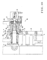
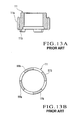
- Figs. 12 to 15 show a driving connecting/disconnecting mechanism employed by a driving apparatus in a conventional printing press.
- a driving gear 106 axially mounted on the end shaft of a plate cylinder is connected to a printing press motor serving as a driving source.
- the plate cylinder rotates through the driving gear 106.
- a first gear 111 is rotatably, axially supported by a shaft 114 extending perpendicularly from a frame 102, such that the movement of the first gear 111 in the axial direction is regulated.
- the first gear 111 has 34 teeth 111a which constantly mesh with 70 teeth 106a of the driving gear 106.
- Four first engaging projections 111b are formed on the side surface of the first gear 111 equiangularly in the rotational direction of the first gear 111.
- a tooth-to-tooth angle ⁇ 2 (Fig. 14C) between the two adjacent teeth 111a of the first gear 111 and a projection-to-projection angle ⁇ 1 (Fig. 14B) between the two adjacent engaging projections 111b are largely different from each other.
- the angle ⁇ 2 is not an integer multiple of the angle ⁇ 1.
- a second gear 112 is rotatably and axially movably supported by an end 114a of the shaft 114 such that it is axially supported to be coaxial with the first gear 111.
- Teeth 112a which constantly mesh with teeth 124a of a driven gear 124 are formed on the circumferential surface of the second gear 112, and engaging projections 112b which engage with the engaging projections 111b of the first gear 111 project from the side surface of the second gear 112.
- the four engaging projections 112b are provided equiangularly with an angle ⁇ 1 in the circumferential direction.
- the driven gear 124 meshes with a gear (not shown) that drives the ink roller of the inking device. When the printing press motor is driven, the plate cylinder rotates, and simultaneously the ink roller is driven in synchronism through the driving gear 106, first and second gears 111 and 112, and driven gear 124.
- an air cylinder 113 is attached, through an auxiliary bracket 117, to a bracket 116 fixed to oppose the frame 102.
- the second gear 112 is mounted on a rod 118 which is driven by the air cylinder 113 to move reciprocally.
- the engaging projections 112b of the second gear 112 engage with the engaging projections 111b of the first gear 111.
- the rod 118 of the air cylinder 113 moves backward, the engaging projections 112b of the second gear 112 and the engaging projections 111b of the first gear 111 disengage from each other.
- the driving force is transmitted by engaging the engaging projections 111b and 112b of the first and second gears 111 and 112, respectively, with each other.
- the pressure of the air of the air cylinder 113 can be decreased comparatively low, the cost does not become high.
- the number (34) of teeth 111a of the first gear 111 and the number (70) of teeth 106a of the driving gear 106 that meshes with the first gear 111 are different from each other.
- their engaging projections 111b and 112b cannot engage with each other again.
- the number of teeth of the driving gear 106 and that of the first gear 111 meshing with the driving gear 106 are different.
- the teeth 111a of the first gear 111 are not located at the same phase as that for disconnection.
- the number i of revolutions of the first gear 111 per revolution of the plate cylinder 1 is 70/34.
- the teeth 111a stop at positions shifted by a phase which is an integer multiple of the angle ⁇ 2.
- the engaging projections 111b of the first gear 111 also stop at the phase shifted from the disconnection phase by an angle which is an integer multiple of the angle ⁇ 2 (Fig. 14B).
- the angle ⁇ 1 is different from the angle ⁇ 2, and the angle ⁇ 2 is not an integer multiple of the angle ⁇ 1.
- the phase of the engaging projections 111b of the first gear 111 stopped at the phase shifted by the integer multiple of the angle ⁇ 2 is located at a phase different from the disconnection phase. For this reason, the phase of the engaging projections 111b of the first gear 111 do not match the phase of the engaging projections 112b of the second gear 112, and the engaging projections 111b and 112b cannot engage with each other again.
- a driving apparatus in a printing press including a first driven device driven by a driving source, a second driven device drive-coupled to the first driven device, and a driving connecting/disconnecting mechanism which connects and disconnects transmission of driving from the first driven device to the second driven device, the driving connecting/disconnecting mechanism including a first engaging member supported rotatably and constantly drive-coupled to one of the first and second driven devices, the first engaging member having a plurality of first engaging portions, and a second engaging member supported rotatably, constantly drive-coupled to the remaining one of the first and second driven devices, and engageable with the first engaging member, the second engaging member having a second engaging portion engageable with the first engaging portions, wherein the first engaging portions have the same shape and are equidistantly arranged in a rotational direction of the first engaging member, when the first and second engaging portions engage, the first and second driven devices are drive-coupled, and when the first and second engaging portions dis
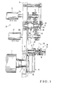
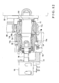
- Figs. 1 to 8C show a driving apparatus in a printing press according to the first embodiment of the present invention.
- a plate cylinder 1 serving as the first driven device is rotatably supported by a pair of frames 2 (one frame is not shown) which oppose end shafts 3.
- a driving gear 4 which is rotated by a printing press motor 5 (Fig. 5) serving as a driving source is axially mounted on the projecting end of the end shaft 3 projecting from the frame 2.
- An intermediate gear 6 is integrally formed with the driving gear 4.
- the intermediate gear 6 has "70" teeth 6a on its circumferential surface.
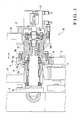
- a driving connecting/disconnecting mechanism 10 includes a ring-like first gear 11 serving as the first engaging member which constantly meshes with the intermediate gear 6, a second gear 12 serving as the sleeve-like second engaging member which meshes with the first gear 11, and an air cylinder 13 serving as a clutch actuator which meshes and disengages the first gear 11 with and from the second gear 12.
- the second gear 12 is rotatably supported by a shaft 14 extending perpendicularly from the frame 2, such that the movement of the second gear 12 in the axial direction is regulated.
- Teeth 12a which constantly mesh with a driven gear 24 (to be described later) are formed on the frame-side portion of the second gear 12.
- Teeth 12b serving as "34" second engaging portions having a small face width are formed on the counter-frame-side portion of the second gear 12.
- the first gear 11 has outer teeth 11a formed on its outer surface to constantly mesh with the teeth 6a of the intermediate gear 6, and inner teeth 11b formed on its inner surface and serving as the first engaging portion to mesh with teeth 12b (first engaging portion) of the second gear 12.
- the number of inner teeth 11b is "34", which is identical to the number of outer teeth 11a.
- the outer and inner teeth 11a and 11b are formed to be related to each other so that the position in the gear rotational direction, i.e., the phase, of the "34" inner teeth 11b and the phase of the "34" outer teeth 11a match each other.
- the air cylinder 13 is fixed through an auxiliary bracket 17 to the bracket 16 attached to the frame 2.
- a substantially cylindrical moving member 19 having a flange 19a at its one end is rotatably and axially movably supported by an end 14a of the shaft 14 through a bearing. The movement of the moving member 19 in the axial direction is regulated by a rod 18 of the air cylinder 13.
- the first gear 11 is fixed to the outer side surface of the flange 19a of the moving member 19.
- the first gear 11 is moved through the moving member 19 in a direction to come close to the frame 2.
- the inner teeth 11b of the first gear 11 mesh with the teeth 12b of the second gear 12, and the rotation of the intermediate gear 6 is transmitted to the second gear 12 through the first gear 11.
- the rod 18 of the air cylinder 13 is moved backward, the inner teeth 11b of the first gear 11 and the teeth 12b of the second gear 12 disengage from each other, and the transmission of rotation from the intermediate gear 6 to the second gear 12 is disconnected.
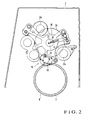
- an inking device 20 serving as the second driven device has two oscillating rollers 21 and 22 which supply ink in an ink fountain (not shown) to a plurality of ink rollers (not shown).
- Shafts 21a and 22a of the rollers 21 and 22 are axially movably and rotatably supported by the frame 2 through bearings (not shown).
- the driven gear 24 which constantly meshes with the second gear 12 is axially mounted on a rotation transmitting shaft 23 having two ends rotatably supported by the frame 2 and a bracket 16.
- the driven gear 24 which constantly meshes with the second gear 12 is indicated by an alternate long and two short dashed line.
- the rotation transmitting shaft 23 has, at its projecting end portion, an oscillating shaft end 23a having an inclined axis.
- the central portion of a driving oscillating lever 25 is rotatably fitted on the oscillating shaft end 23a such that the oscillating lever 25 will not disengage in the axial direction of the oscillating shaft end 23a.
- the two ends of the driving oscillating lever 25 engage with the distal ends of the shafts 21a and 22a of the oscillating rollers 21 and 22, respectively, such that the driving oscillating lever 25 will not disengage in the axial direction.
- a dog 27 serving as a detector is fixed to the end face of the rotation transmitting shaft 23.
- a home position sensor 28 which detects the dog 27 is attached to the bracket 16.
- the printing press motor 5 which drives the printing press, the air cylinder 13 described above, the home position sensor 28 which detects the dog 27, and a printing press encoder 29 which detects the phase of the printing press are connected to a controller 30.
- the controller 30 controls the driving operation of the printing press motor 5 and air cylinder 13.
- the printing press motor 5 keeps driving until the home position sensor 28 detects the dog 27.
- the controller 30 controls to stop the driving operation of the printing press motor 5.
- the phase of the printing press is detected by the printing press encoder 29, and the detected phase, i.e., the phase during disconnection of the driving connecting/disconnecting mechanism 10, is stored in the controller 30.
- the controller 30 moves the rod 18 backward as an inoperative state of the air cylinder 13.
- the inner teeth 11b of the first gear 11 and the teeth 12b of the second gear 12 disengage from each other, and the first and second gears 11 and 12 are disconnected from each other. Therefore, the driving operation of the printing press motor 5 to the rotation transmitting shaft 23 is disconnected, so that the reciprocal movement of the oscillating rollers 21 and 22 is stopped.
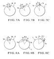
- the phase (Fig. 7A) of the teeth 12b of the second gear 12 and the phase (Fig. 7B) of the inner teeth 11b of the first gear 11 match each other, as shown in Fig. 6.
- the inner teeth 11b and teeth 12b establish such a phase relationship that they can engage with each other.
- the hatched outer tooth 11a (Fig. 7C) indicates the expedient phase of the first gear 11 where the first and second gears 11 and 12 are disconnected from each other.
- the controller 30 detects the stored phase of the printing press in response to an output from the printing press encoder 29.
- the controller 30 stops the printing press motor 5.
- the number of teeth 6a of the intermediate gear 6 and that of the outer teeth 11a of the first gear 11 differ, and accordingly the phase of the first gear 11 is sometimes shifted. More specifically, as indicated by the hatched outer tooth 11a, sometimes the first gear 11 is located at a phase (Fig. 8C) which is shifted from the phase (Fig. 7C) the first and second gears 11 and 12 are disconnected by an angle which is an integer multiple of ⁇ . Accordingly, the inner teeth 11b of the first gear 11 are also located at a phase (Fig. 8B) which is shifted from the phase (Fig. 7B) where the first and second gears 11 and 12 are disconnected by an angle which is an integer multiple of ⁇ .
- the adjacent inner teeth 11b of the first gear 11 are formed to have a tooth-to-tooth angle ⁇ which is equal to the tooth-to-tooth angle of the adjacent outer teeth 11a. Accordingly, when the first and second gears 11 and 12 are connected to each other again, the phase (Fig. 8B) of the inneer teeth 11b of the first gear 11 match the phase (Fig. 7B) of the inner teeth 11b where the first and second gears 11 and 12 are disconnected. Therefore, when the first and second gears 11 and 12 are to be connected to each other again, the relationship between the phase (Fig. 8B) of the inner teeth 11b of the first gear 11 and the phase (Fig. 8A) of the teeth 12b of the second gear 12 establishes the same phase relationship as that shown in Figs.
- connection and disconnection by the driving connecting/disconnecting mechanism 10 are performed by meshing/disengaging the inner teeth 11b of the first gear 11 and the teeth 12b of the second gear 12 with/from each other.
- a relatively inexpensive air cylinder can be used as the air cylinder 13.
- the phase of the each of the "34" inner teeth 11b in the rotational direction of the first gear 11 and the phase of each of the "34" outer teeth 11a match each other.
- the two phases need not match each other, and it suffices as far as the number of inner teeth 11b and that of the outer teeth 11a are equal.
- engaging portions such as engaging projections may be formed.
- the plurality of engaging portions have the same shape and are arranged equidistantly in the rotational direction of the first gear 11.
- the engaging portions may be formed in the same number as that of the outer teeth 11a of the first gear 11, and engaging portions engageable with these engaging portions may be formed on the second gear 12 as well.
- the number of teeth 12b of the second gear 12 is equal to that of the inner teeth 11b of the first gear 11, that is, 34, but they need not be equal. For example, it suffices as far as the second gear 12 has at least "one" tooth 12b.
- the number of outer teeth 11a of the first gear 11 is equal to that of the inner teeth 11b, but even when the number of inner teeth 11b is an integer multiple of the number of outer teeth 11a, the same function and effect can be obtained. In this case, the number of outer teeth 11a corresponds to a value related to the first gear 11 (first engaging member).
- the first gear 11 meshes with the driving gear 4 on the plate cylinder 1 side.
- the first gear 11 may mesh with the driven gear 24 on the inking device 20 side
- the second gear 12 may mesh with the driving gear 4.
- the second gear 12 has a plurality of teeth 12b, but it suffices as far as the second gear 12 has at least one tooth 12b to be able to mesh with any one of the plurality of inner teeth 11b of the first gear 11.
- the first gear 11 meshes with the intermediate gear 6 on the plate cylinder side.
- the first gear 11 may mesh with the driven gear 24 of the inking device 20, and the second gear 12 may mesh with the intermediate gear 6 on the plate cylinder side.
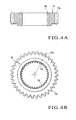
- Figs. 9A and 9B show the second embodiment of the present invention.
- spline grooves 11c are formed in the inner surface of a first gear 11, and teeth 12b of a second gear 12 that engage with the grooves 11c are spline teeth.
- the second embodiment is different from the first embodiment in these respects.
- the grooves 11c of the first gear 11 are located at the same positions as those for disconnection, in the same manner as in the first embodiment. This will be described.
- the number of revolutions of the first gear 11 per revolution of the plate cylinder 1 is defined as "i”.
- the first gear 11 rotates by i revolutions.
- an intermediate gear 6 is integrally formed with the plate cylinder 1 and that the first gear 11 meshes with the intermediate gear 6.
- a number Z 1 of teeth 6a of the intermediate gear 6 is "70” and a number Z 2 of outer teeth 11a of the first gear 11 is "34”
- the first gear 11 rotates by 2 and 1/17 revolutions, which is equivalent to an angle 35 times an angle obtained by equally dividing 360° by 17.
- the first gear 11 is shifted by an integer multiple of the angle obtained by equally dividing 360° by 17.
- the grooves 11c can be positioned at the same positions as those for disconnection.
- Fig. 10 shows the third embodiment of the present invention.
- other intermediate gears 40 and 41 are interposed between a first gear 11 and an intermediate gear 6 which is integrally formed with a plate cylinder 1.
- the third embodiment in the same manner as in the second embodiment, when the number of inner teeth 11b of the first gear 11 is determined on the basis of the number i of revolutions of the first gear 11 per revolution of the plate cylinder 1, the same effect as that of the second embodiment can be obtained.
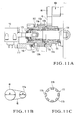
- Figs. 11A to 11C show the fourth embodiment of the present invention.
- the same or equivalent members as those described in the prior art shown in Fig. 12 are denoted by the same reference numerals, and a detailed description will be omitted when necessary.
- a gear 106 is integrally formed with a pulley 44, and a first engaging member 111 is integrally formed with a pulley 111c.
- a belt 45 extends between the pulleys 44 and 111c, as shown in Fig. 11B. The driving operation of a printing press motor 5 is transmitted to the first engaging member 111 through the belt 45.
- the number of engaging projections 111b of the first engaging member 111 may be set to "8", so that the engaging projections 111b can be positioned at the same phase as that for disconnection.
- the number of engaging projections 111b may be set to "16" or "24", each of which is an integer multiple of 8.
- the first driven device is the plate cylinder 1, and the second driven device is the inking device 20.
- the second driven device may be a dampening unit.
- the present invention can also be applied to a case wherein the first driven device is a printing press, the second driven device is a folder, and the driving operations of the two devices are connected and disconnected for the purpose of preparation of printing.
- the first driven device may be a printing press, and the second driven device may be a sheet feeder.
- the first driven device may be a printing press, and the second driven device may be a delivery unit.
- the driving force can be connected reliably at a low cost.
Landscapes
- Engineering & Computer Science (AREA)
- Mechanical Engineering (AREA)
- General Engineering & Computer Science (AREA)
- Inking, Control Or Cleaning Of Printing Machines (AREA)
- Rotary Presses (AREA)
Applications Claiming Priority (2)
| Application Number | Priority Date | Filing Date | Title |
|---|---|---|---|
| JP2003200996 | 2003-07-24 | ||
| JP2003200996A JP4276010B2 (ja) | 2003-07-24 | 2003-07-24 | 印刷機における駆動装置 |
Publications (2)
| Publication Number | Publication Date |
|---|---|
| EP1500501A2 true EP1500501A2 (fr) | 2005-01-26 |
| EP1500501A3 EP1500501A3 (fr) | 2009-01-14 |
Family
ID=33487648
Family Applications (1)
| Application Number | Title | Priority Date | Filing Date |
|---|---|---|---|
| EP04016459A Withdrawn EP1500501A3 (fr) | 2003-07-24 | 2004-07-13 | Dispositif d'entaînement dans machines à impression |
Country Status (4)
| Country | Link |
|---|---|
| US (1) | US7096782B2 (fr) |
| EP (1) | EP1500501A3 (fr) |
| JP (1) | JP4276010B2 (fr) |
| CN (1) | CN1310752C (fr) |
Cited By (1)
| Publication number | Priority date | Publication date | Assignee | Title |
|---|---|---|---|---|
| CN111605292A (zh) * | 2020-06-30 | 2020-09-01 | 深圳弘博智能数码设备有限公司 | 柔印小车模组及印刷设备 |
Families Citing this family (6)
| Publication number | Priority date | Publication date | Assignee | Title |
|---|---|---|---|---|
| JP5113353B2 (ja) * | 2006-07-18 | 2013-01-09 | 株式会社ミヤコシ | 交換胴型輪転機 |
| DE102009045922B4 (de) * | 2009-10-22 | 2014-08-14 | Koenig & Bauer Aktiengesellschaft | Vorrichtung in einem Druckwerk einer Druckmaschine |
| US20110185926A1 (en) * | 2010-02-02 | 2011-08-04 | Gross International Americas, Inc. | Vibrator assembly for an inking unit or a dampening unit of a printing press |
| US8783177B2 (en) * | 2011-10-19 | 2014-07-22 | Brian Giardino | System for oscillating a roller |
| CN103963450A (zh) * | 2014-05-09 | 2014-08-06 | 于法周 | 一种用于驱动传墨辊的双齿调节辊 |
| CN112967573B (zh) * | 2021-03-12 | 2023-03-21 | 焦作大学 | 一种教学装置 |
Family Cites Families (20)
| Publication number | Priority date | Publication date | Assignee | Title |
|---|---|---|---|---|
| DE2845932A1 (de) * | 1978-10-21 | 1980-04-24 | Heidelberger Druckmasch Ag | Kombiniertes feucht-farbwerk fuer offsetdruckwerke |
| SE426153B (sv) * | 1979-01-22 | 1982-12-13 | Wifag Maschf | Drivanordning for en valsrotations offsettryckmaskin |
| US4798137A (en) * | 1979-04-20 | 1989-01-17 | Publishers Equipment Corporation | Conversion of letterpress to offset printing |
| JP2537504B2 (ja) | 1987-02-17 | 1996-09-25 | 株式会社シマノ | ブレ―キ圧接力制御装置 |
| DE3923315A1 (de) * | 1989-07-14 | 1991-04-04 | Roland Man Druckmasch | Antrieb fuer die umlaufende und seitlich hin- und hergehende reibwalze in farb- oder feuchtwerken von offset-druckmaschinen |
| DE4231260C2 (de) * | 1992-09-18 | 1996-05-23 | Heidelberger Druckmasch Ag | Druckantrieb für Farbtransportwalzen einer Rotationsdruckmaschine |
| DE4344365C2 (de) * | 1993-12-24 | 1997-09-18 | Koenig & Bauer Albert Ag | Druckwerk für eine Rotationsdruckmaschine |
| DE19504426C2 (de) * | 1995-02-10 | 2000-05-11 | Heidelberger Druckmasch Ag | Antrieb für Reibwalzen im Farbwerk von Rotationsdruckmaschinen |
| JPH0970950A (ja) * | 1995-09-04 | 1997-03-18 | Komori Corp | 印刷機の駆動装置 |
| JP3761945B2 (ja) * | 1995-11-21 | 2006-03-29 | 株式会社小森コーポレーション | 印刷機の駆動装置 |
| US6293194B1 (en) * | 1996-05-07 | 2001-09-25 | Heidelberg Harris Inc. | Method and apparatus for adjusting the circumferential register in a web-fed rotary printing press having a plate cylinder with a sleeve-shaped printing plate |
| DE19625029A1 (de) * | 1996-06-22 | 1998-01-08 | Roland Man Druckmasch | Offsetdruckvorrichtung für Rotationsdruckmaschinen |
| US5706728A (en) * | 1996-07-30 | 1998-01-13 | Rdp Marathon Inc. | Printing apparatus |
| JP3889884B2 (ja) * | 1998-07-31 | 2007-03-07 | 株式会社小森コーポレーション | 駆動連結装置 |
| JP3556130B2 (ja) * | 1999-08-03 | 2004-08-18 | リョービ株式会社 | オフセット印刷機 |
| JP4235960B2 (ja) * | 1999-09-17 | 2009-03-11 | 株式会社ミヤコシ | 長尺印刷物用印刷装置 |
| EP1147889A3 (fr) * | 2000-04-14 | 2006-01-18 | Komori Corporation | Structure de rouleau dans une machine à imprimer. |
| JP4582867B2 (ja) * | 2000-06-23 | 2010-11-17 | 株式会社小森コーポレーション | 印刷機 |
| JP2002210915A (ja) * | 2001-01-22 | 2002-07-31 | Tokyo Kikai Seisakusho Ltd | 分割版胴を個別に駆動する多色刷平版印刷機 |
| US6796239B2 (en) * | 2001-03-22 | 2004-09-28 | Heidelberger Druckmaschinen Ag | Method and device for driving a printing press |
-
2003
- 2003-07-24 JP JP2003200996A patent/JP4276010B2/ja not_active Expired - Fee Related
-
2004
- 2004-07-13 EP EP04016459A patent/EP1500501A3/fr not_active Withdrawn
- 2004-07-22 CN CNB2004100544806A patent/CN1310752C/zh not_active Expired - Fee Related
- 2004-07-23 US US10/898,090 patent/US7096782B2/en not_active Expired - Fee Related
Cited By (2)
| Publication number | Priority date | Publication date | Assignee | Title |
|---|---|---|---|---|
| CN111605292A (zh) * | 2020-06-30 | 2020-09-01 | 深圳弘博智能数码设备有限公司 | 柔印小车模组及印刷设备 |
| CN111605292B (zh) * | 2020-06-30 | 2024-05-14 | 深圳弘博智能数码设备有限公司 | 柔印小车模组及印刷设备 |
Also Published As
| Publication number | Publication date |
|---|---|
| CN1310752C (zh) | 2007-04-18 |
| US7096782B2 (en) | 2006-08-29 |
| JP2005041019A (ja) | 2005-02-17 |
| JP4276010B2 (ja) | 2009-06-10 |
| EP1500501A3 (fr) | 2009-01-14 |
| US20050016396A1 (en) | 2005-01-27 |
| CN1575987A (zh) | 2005-02-09 |
Similar Documents
| Publication | Publication Date | Title |
|---|---|---|
| US5535675A (en) | Apparatus for circumferential and lateral adjustment of plate cylinder | |
| US6655278B2 (en) | Apparatus for fine positional adjustment of a plate cylinder for multicolor image registration | |
| US5964150A (en) | Couple of gear wheels for driving printing drum with means for mutual phase restoration | |
| US7096782B2 (en) | Driving apparatus in printing press | |
| CN102348554B (zh) | 具有至少一个印刷装置的印刷机印刷单元 | |
| US6634292B2 (en) | Printing press with means for connecting and disconnecting motors for oscillating roller | |
| US6546865B2 (en) | Drive for a distributor roller in a printing machine | |
| US4833983A (en) | Adjustment apparatus for adjusting the speed of a plate roller relative to a pressing roller in a multi-color plastic bag printer | |
| US6776093B2 (en) | Drive system for a printing group | |
| US20070245911A1 (en) | Drive for a Rotary Printing Press | |
| US6698352B2 (en) | Inking apparatus control means for rotary press | |
| EP1700697A2 (fr) | Dispositif pour entraîner en rotation un rouleau | |
| JP2003080677A (ja) | 輪転印刷機 | |
| JPH0592558A (ja) | 多色回転式印刷機において各単色像を相互に調整する方法 | |
| US6851368B2 (en) | Rotary printing press having a switchable speed-change gear mechanism with plant gears | |
| US6923118B2 (en) | Drive for impression cylinders of a rotary press | |
| US20070277688A1 (en) | Printing couple of a printing unit of a printing press | |
| JPS6313006Y2 (fr) | ||
| JP2004518568A (ja) | 胴の駆動装置 | |
| US20080163773A1 (en) | Inking Systems of a Printing Press and Method for Operating an Inking System | |
| US20070182092A1 (en) | Dual-speed drive mechanism | |
| JP2004351692A (ja) | 印刷機の位相調整装置 | |
| JPH10202826A (ja) | 輪転印刷機における版胴装置 | |
| JPH02171245A (ja) | インキローラ駆動装置 | |
| JP2003039629A (ja) | 平坦な被印刷体を処理する機械の歯車列 |
Legal Events
| Date | Code | Title | Description |
|---|---|---|---|
| PUAI | Public reference made under article 153(3) epc to a published international application that has entered the european phase |
Free format text: ORIGINAL CODE: 0009012 |
|
| AK | Designated contracting states |
Kind code of ref document: A2 Designated state(s): AT BE BG CH CY CZ DE DK EE ES FI FR GB GR HU IE IT LI LU MC NL PL PT RO SE SI SK TR |
|
| AX | Request for extension of the european patent |
Extension state: AL HR LT LV MK |
|
| PUAL | Search report despatched |
Free format text: ORIGINAL CODE: 0009013 |
|
| AK | Designated contracting states |
Kind code of ref document: A3 Designated state(s): AT BE BG CH CY CZ DE DK EE ES FI FR GB GR HU IE IT LI LU MC NL PL PT RO SE SI SK TR |
|
| AX | Request for extension of the european patent |
Extension state: AL HR LT LV MK |
|
| 17P | Request for examination filed |
Effective date: 20090713 |
|
| 17Q | First examination report despatched |
Effective date: 20090811 |
|
| AKX | Designation fees paid |
Designated state(s): AT BE BG CH CY CZ DE DK EE ES FI FR GB GR HU IE IT LI LU MC NL PL PT RO SE SI SK TR |
|
| STAA | Information on the status of an ep patent application or granted ep patent |
Free format text: STATUS: THE APPLICATION IS DEEMED TO BE WITHDRAWN |
|
| 18D | Application deemed to be withdrawn |
Effective date: 20091222 |