EP1500498B1 - Flachdruckplattenvorläufer und lithographisches Druckverfahren - Google Patents
Flachdruckplattenvorläufer und lithographisches Druckverfahren Download PDFInfo
- Publication number
- EP1500498B1 EP1500498B1 EP04017306A EP04017306A EP1500498B1 EP 1500498 B1 EP1500498 B1 EP 1500498B1 EP 04017306 A EP04017306 A EP 04017306A EP 04017306 A EP04017306 A EP 04017306A EP 1500498 B1 EP1500498 B1 EP 1500498B1
- Authority
- EP
- European Patent Office
- Prior art keywords
- group
- lithographic printing
- printing plate
- plate precursor
- image
- Prior art date
- Legal status (The legal status is an assumption and is not a legal conclusion. Google has not performed a legal analysis and makes no representation as to the accuracy of the status listed.)
- Expired - Lifetime
Links
- 238000007639 printing Methods 0.000 title claims abstract description 257
- 238000000034 method Methods 0.000 title claims description 102
- 150000001875 compounds Chemical class 0.000 claims abstract description 147
- 239000002243 precursor Substances 0.000 claims abstract description 144
- 125000000524 functional group Chemical group 0.000 claims abstract description 50
- 239000003505 polymerization initiator Substances 0.000 claims abstract description 30
- 230000003993 interaction Effects 0.000 claims abstract description 20
- 229910052782 aluminium Inorganic materials 0.000 claims description 66
- XAGFODPZIPBFFR-UHFFFAOYSA-N aluminium Chemical group [Al] XAGFODPZIPBFFR-UHFFFAOYSA-N 0.000 claims description 63
- 125000003118 aryl group Chemical group 0.000 claims description 43
- 125000001931 aliphatic group Chemical group 0.000 claims description 38
- 125000005843 halogen group Chemical group 0.000 claims description 29
- 125000000217 alkyl group Chemical group 0.000 claims description 28
- 125000004435 hydrogen atom Chemical group [H]* 0.000 claims description 27
- 125000000623 heterocyclic group Chemical group 0.000 claims description 26
- 238000011161 development Methods 0.000 claims description 25
- 125000001841 imino group Chemical group [H]N=* 0.000 claims description 25
- 239000003094 microcapsule Substances 0.000 claims description 25
- 239000002250 absorbent Substances 0.000 claims description 21
- 230000002745 absorbent Effects 0.000 claims description 21
- 125000004430 oxygen atom Chemical group O* 0.000 claims description 21
- BPQQTUXANYXVAA-UHFFFAOYSA-N Orthosilicate Chemical group [O-][Si]([O-])([O-])[O-] BPQQTUXANYXVAA-UHFFFAOYSA-N 0.000 claims description 16
- 125000002915 carbonyl group Chemical group [*:2]C([*:1])=O 0.000 claims description 16
- 229910052717 sulfur Inorganic materials 0.000 claims description 14
- 125000004434 sulfur atom Chemical group 0.000 claims description 12
- NINIDFKCEFEMDL-UHFFFAOYSA-N Sulfur Chemical group [S] NINIDFKCEFEMDL-UHFFFAOYSA-N 0.000 claims description 5
- 239000010410 layer Substances 0.000 description 210
- -1 polyethylene Polymers 0.000 description 114
- 239000000975 dye Substances 0.000 description 99
- 239000000243 solution Substances 0.000 description 74
- 229920000642 polymer Polymers 0.000 description 57
- 238000000576 coating method Methods 0.000 description 56
- 239000011248 coating agent Substances 0.000 description 51
- 239000004094 surface-active agent Substances 0.000 description 48
- 239000000049 pigment Substances 0.000 description 43
- 239000011230 binding agent Substances 0.000 description 42
- 239000002253 acid Substances 0.000 description 39
- 150000002148 esters Chemical class 0.000 description 37
- 125000004432 carbon atom Chemical group C* 0.000 description 35
- 239000003921 oil Substances 0.000 description 34
- 125000001424 substituent group Chemical group 0.000 description 28
- XLYOFNOQVPJJNP-UHFFFAOYSA-N water Substances O XLYOFNOQVPJJNP-UHFFFAOYSA-N 0.000 description 28
- 230000035945 sensitivity Effects 0.000 description 27
- 239000000126 substance Substances 0.000 description 25
- OKKJLVBELUTLKV-UHFFFAOYSA-N Methanol Chemical compound OC OKKJLVBELUTLKV-UHFFFAOYSA-N 0.000 description 24
- 239000000203 mixture Substances 0.000 description 24
- 239000011241 protective layer Substances 0.000 description 23
- 229920001577 copolymer Polymers 0.000 description 22
- 150000003839 salts Chemical class 0.000 description 22
- ZWEHNKRNPOVVGH-UHFFFAOYSA-N 2-Butanone Chemical compound CCC(C)=O ZWEHNKRNPOVVGH-UHFFFAOYSA-N 0.000 description 21
- 239000007864 aqueous solution Substances 0.000 description 20
- 125000002887 hydroxy group Chemical group [H]O* 0.000 description 20
- 239000000463 material Substances 0.000 description 20
- 150000003254 radicals Chemical class 0.000 description 20
- 239000007787 solid Substances 0.000 description 19
- 238000006116 polymerization reaction Methods 0.000 description 18
- ANRHNWWPFJCPAZ-UHFFFAOYSA-M thionine Chemical compound [Cl-].C1=CC(N)=CC2=[S+]C3=CC(N)=CC=C3N=C21 ANRHNWWPFJCPAZ-UHFFFAOYSA-M 0.000 description 16
- 239000011737 fluorine Substances 0.000 description 15
- 229910052731 fluorine Inorganic materials 0.000 description 15
- 238000007788 roughening Methods 0.000 description 15
- YCKRFDGAMUMZLT-UHFFFAOYSA-N Fluorine atom Chemical compound [F] YCKRFDGAMUMZLT-UHFFFAOYSA-N 0.000 description 14
- 239000003999 initiator Substances 0.000 description 14
- QAOWNCQODCNURD-UHFFFAOYSA-N Sulfuric acid Chemical class OS(O)(=O)=O QAOWNCQODCNURD-UHFFFAOYSA-N 0.000 description 13
- 239000000178 monomer Substances 0.000 description 13
- 229910052760 oxygen Inorganic materials 0.000 description 13
- XEKOWRVHYACXOJ-UHFFFAOYSA-N Ethyl acetate Chemical compound CCOC(C)=O XEKOWRVHYACXOJ-UHFFFAOYSA-N 0.000 description 12
- QVGXLLKOCUKJST-UHFFFAOYSA-N atomic oxygen Chemical compound [O] QVGXLLKOCUKJST-UHFFFAOYSA-N 0.000 description 12
- 239000003792 electrolyte Substances 0.000 description 12
- 239000001301 oxygen Substances 0.000 description 12
- 239000002245 particle Substances 0.000 description 12
- FBPFZTCFMRRESA-FSIIMWSLSA-N D-Glucitol Natural products OC[C@H](O)[C@H](O)[C@@H](O)[C@H](O)CO FBPFZTCFMRRESA-FSIIMWSLSA-N 0.000 description 11
- 150000001408 amides Chemical class 0.000 description 11
- 230000000052 comparative effect Effects 0.000 description 11
- 239000002904 solvent Substances 0.000 description 11
- 239000000600 sorbitol Substances 0.000 description 11
- FBPFZTCFMRRESA-JGWLITMVSA-N D-glucitol Chemical compound OC[C@H](O)[C@@H](O)[C@H](O)[C@H](O)CO FBPFZTCFMRRESA-JGWLITMVSA-N 0.000 description 10
- 238000002048 anodisation reaction Methods 0.000 description 10
- 125000003178 carboxy group Chemical group [H]OC(*)=O 0.000 description 10
- 238000009472 formulation Methods 0.000 description 10
- 125000000449 nitro group Chemical group [O-][N+](*)=O 0.000 description 10
- 239000011236 particulate material Substances 0.000 description 10
- 229920002451 polyvinyl alcohol Polymers 0.000 description 10
- 235000019422 polyvinyl alcohol Nutrition 0.000 description 10
- 125000003396 thiol group Chemical class [H]S* 0.000 description 10
- HEMHJVSKTPXQMS-UHFFFAOYSA-M Sodium hydroxide Chemical compound [OH-].[Na+] HEMHJVSKTPXQMS-UHFFFAOYSA-M 0.000 description 9
- 125000003277 amino group Chemical group 0.000 description 9
- 229920001519 homopolymer Polymers 0.000 description 9
- 229910052751 metal Inorganic materials 0.000 description 9
- 239000002184 metal Substances 0.000 description 9
- 238000003892 spreading Methods 0.000 description 9
- 230000007480 spreading Effects 0.000 description 9
- 238000004381 surface treatment Methods 0.000 description 9
- ARXJGSRGQADJSQ-UHFFFAOYSA-N 1-methoxypropan-2-ol Chemical compound COCC(C)O ARXJGSRGQADJSQ-UHFFFAOYSA-N 0.000 description 8
- LFQSCWFLJHTTHZ-UHFFFAOYSA-N Ethanol Chemical compound CCO LFQSCWFLJHTTHZ-UHFFFAOYSA-N 0.000 description 8
- 239000004372 Polyvinyl alcohol Substances 0.000 description 8
- 239000000470 constituent Substances 0.000 description 8
- DZVCFNFOPIZQKX-LTHRDKTGSA-M merocyanine Chemical compound [Na+].O=C1N(CCCC)C(=O)N(CCCC)C(=O)C1=C\C=C\C=C/1N(CCCS([O-])(=O)=O)C2=CC=CC=C2O\1 DZVCFNFOPIZQKX-LTHRDKTGSA-M 0.000 description 8
- 125000002560 nitrile group Chemical group 0.000 description 8
- 230000001235 sensitizing effect Effects 0.000 description 8
- RTZKZFJDLAIYFH-UHFFFAOYSA-N Diethyl ether Chemical compound CCOCC RTZKZFJDLAIYFH-UHFFFAOYSA-N 0.000 description 7
- 229920003171 Poly (ethylene oxide) Polymers 0.000 description 7
- 239000000654 additive Substances 0.000 description 7
- 125000003545 alkoxy group Chemical group 0.000 description 7
- 230000015572 biosynthetic process Effects 0.000 description 7
- PESYEWKSBIWTAK-UHFFFAOYSA-N cyclopenta-1,3-diene;titanium(2+) Chemical compound [Ti+2].C=1C=C[CH-]C=1.C=1C=C[CH-]C=1 PESYEWKSBIWTAK-UHFFFAOYSA-N 0.000 description 7
- 238000005516 engineering process Methods 0.000 description 7
- 238000011156 evaluation Methods 0.000 description 7
- 238000003860 storage Methods 0.000 description 7
- JOYRKODLDBILNP-UHFFFAOYSA-N urethane group Chemical group NC(=O)OCC JOYRKODLDBILNP-UHFFFAOYSA-N 0.000 description 7
- WNZQDUSMALZDQF-UHFFFAOYSA-N 2-benzofuran-1(3H)-one Chemical compound C1=CC=C2C(=O)OCC2=C1 WNZQDUSMALZDQF-UHFFFAOYSA-N 0.000 description 6
- 229920002134 Carboxymethyl cellulose Polymers 0.000 description 6
- VEXZGXHMUGYJMC-UHFFFAOYSA-N Hydrochloric acid Chemical compound Cl VEXZGXHMUGYJMC-UHFFFAOYSA-N 0.000 description 6
- ZMXDDKWLCZADIW-UHFFFAOYSA-N N,N-Dimethylformamide Chemical compound CN(C)C=O ZMXDDKWLCZADIW-UHFFFAOYSA-N 0.000 description 6
- GRYLNZFGIOXLOG-UHFFFAOYSA-N Nitric acid Chemical compound O[N+]([O-])=O GRYLNZFGIOXLOG-UHFFFAOYSA-N 0.000 description 6
- MUBZPKHOEPUJKR-UHFFFAOYSA-N Oxalic acid Chemical compound OC(=O)C(O)=O MUBZPKHOEPUJKR-UHFFFAOYSA-N 0.000 description 6
- ABLZXFCXXLZCGV-UHFFFAOYSA-N Phosphorous acid Chemical compound OP(O)=O ABLZXFCXXLZCGV-UHFFFAOYSA-N 0.000 description 6
- DNIAPMSPPWPWGF-UHFFFAOYSA-N Propylene glycol Chemical compound CC(O)CO DNIAPMSPPWPWGF-UHFFFAOYSA-N 0.000 description 6
- YXFVVABEGXRONW-UHFFFAOYSA-N Toluene Chemical compound CC1=CC=CC=C1 YXFVVABEGXRONW-UHFFFAOYSA-N 0.000 description 6
- 238000010521 absorption reaction Methods 0.000 description 6
- 125000003342 alkenyl group Chemical group 0.000 description 6
- 125000000129 anionic group Chemical group 0.000 description 6
- 239000008346 aqueous phase Substances 0.000 description 6
- 235000010948 carboxy methyl cellulose Nutrition 0.000 description 6
- 150000001732 carboxylic acid derivatives Chemical class 0.000 description 6
- 238000006243 chemical reaction Methods 0.000 description 6
- 239000003086 colorant Substances 0.000 description 6
- 238000004132 cross linking Methods 0.000 description 6
- 239000012153 distilled water Substances 0.000 description 6
- 238000005868 electrolysis reaction Methods 0.000 description 6
- 238000005530 etching Methods 0.000 description 6
- LYCAIKOWRPUZTN-UHFFFAOYSA-N ethylene glycol Natural products OCCO LYCAIKOWRPUZTN-UHFFFAOYSA-N 0.000 description 6
- 150000002430 hydrocarbons Chemical group 0.000 description 6
- RKJUIXBNRJVNHR-UHFFFAOYSA-N indolenine group Chemical group N1=CCC2=CC=CC=C12 RKJUIXBNRJVNHR-UHFFFAOYSA-N 0.000 description 6
- ZFSLODLOARCGLH-UHFFFAOYSA-N isocyanuric acid Chemical compound OC1=NC(O)=NC(O)=N1 ZFSLODLOARCGLH-UHFFFAOYSA-N 0.000 description 6
- 125000001570 methylene group Chemical group [H]C([H])([*:1])[*:2] 0.000 description 6
- 229910017604 nitric acid Inorganic materials 0.000 description 6
- 239000012071 phase Substances 0.000 description 6
- 239000000047 product Substances 0.000 description 6
- 229920005989 resin Polymers 0.000 description 6
- 239000011347 resin Substances 0.000 description 6
- PEDCQBHIVMGVHV-UHFFFAOYSA-N Glycerol Natural products OCC(O)CO PEDCQBHIVMGVHV-UHFFFAOYSA-N 0.000 description 5
- XEEYBQQBJWHFJM-UHFFFAOYSA-N Iron Chemical compound [Fe] XEEYBQQBJWHFJM-UHFFFAOYSA-N 0.000 description 5
- 239000004698 Polyethylene Substances 0.000 description 5
- VYPSYNLAJGMNEJ-UHFFFAOYSA-N Silicium dioxide Chemical compound O=[Si]=O VYPSYNLAJGMNEJ-UHFFFAOYSA-N 0.000 description 5
- 238000002835 absorbance Methods 0.000 description 5
- 125000000304 alkynyl group Chemical group 0.000 description 5
- 125000004104 aryloxy group Chemical group 0.000 description 5
- 230000004888 barrier function Effects 0.000 description 5
- 125000002091 cationic group Chemical group 0.000 description 5
- 125000004122 cyclic group Chemical group 0.000 description 5
- 125000005842 heteroatom Chemical group 0.000 description 5
- 239000003112 inhibitor Substances 0.000 description 5
- 230000000977 initiatory effect Effects 0.000 description 5
- 238000004519 manufacturing process Methods 0.000 description 5
- 229910052757 nitrogen Inorganic materials 0.000 description 5
- 125000001820 oxy group Chemical group [*:1]O[*:2] 0.000 description 5
- 125000005010 perfluoroalkyl group Chemical group 0.000 description 5
- PTMHPRAIXMAOOB-UHFFFAOYSA-N phosphoramidic acid Chemical compound NP(O)(O)=O PTMHPRAIXMAOOB-UHFFFAOYSA-N 0.000 description 5
- 150000003014 phosphoric acid esters Chemical class 0.000 description 5
- 239000004014 plasticizer Substances 0.000 description 5
- 229920000573 polyethylene Polymers 0.000 description 5
- 230000008569 process Effects 0.000 description 5
- 238000012545 processing Methods 0.000 description 5
- 239000004065 semiconductor Substances 0.000 description 5
- 125000000020 sulfo group Chemical group O=S(=O)([*])O[H] 0.000 description 5
- 125000001174 sulfone group Chemical group 0.000 description 5
- 125000003375 sulfoxide group Chemical group 0.000 description 5
- IANQTJSKSUMEQM-UHFFFAOYSA-N 1-benzofuran Chemical group C1=CC=C2OC=CC2=C1 IANQTJSKSUMEQM-UHFFFAOYSA-N 0.000 description 4
- XLLIQLLCWZCATF-UHFFFAOYSA-N 2-methoxyethyl acetate Chemical compound COCCOC(C)=O XLLIQLLCWZCATF-UHFFFAOYSA-N 0.000 description 4
- 235000011960 Brassica ruvo Nutrition 0.000 description 4
- CURLTUGMZLYLDI-UHFFFAOYSA-N Carbon dioxide Chemical group O=C=O CURLTUGMZLYLDI-UHFFFAOYSA-N 0.000 description 4
- IAZDPXIOMUYVGZ-UHFFFAOYSA-N Dimethylsulphoxide Chemical compound CS(C)=O IAZDPXIOMUYVGZ-UHFFFAOYSA-N 0.000 description 4
- 239000004793 Polystyrene Substances 0.000 description 4
- JUJWROOIHBZHMG-UHFFFAOYSA-N Pyridine Chemical compound C1=CC=NC=C1 JUJWROOIHBZHMG-UHFFFAOYSA-N 0.000 description 4
- 239000004115 Sodium Silicate Substances 0.000 description 4
- PPBRXRYQALVLMV-UHFFFAOYSA-N Styrene Chemical compound C=CC1=CC=CC=C1 PPBRXRYQALVLMV-UHFFFAOYSA-N 0.000 description 4
- RTAQQCXQSZGOHL-UHFFFAOYSA-N Titanium Chemical compound [Ti] RTAQQCXQSZGOHL-UHFFFAOYSA-N 0.000 description 4
- ZJCCRDAZUWHFQH-UHFFFAOYSA-N Trimethylolpropane Chemical compound CCC(CO)(CO)CO ZJCCRDAZUWHFQH-UHFFFAOYSA-N 0.000 description 4
- 235000010724 Wisteria floribunda Nutrition 0.000 description 4
- HVVWZTWDBSEWIH-UHFFFAOYSA-N [2-(hydroxymethyl)-3-prop-2-enoyloxy-2-(prop-2-enoyloxymethyl)propyl] prop-2-enoate Chemical compound C=CC(=O)OCC(CO)(COC(=O)C=C)COC(=O)C=C HVVWZTWDBSEWIH-UHFFFAOYSA-N 0.000 description 4
- 125000000641 acridinyl group Chemical group C1(=CC=CC2=NC3=CC=CC=C3C=C12)* 0.000 description 4
- 125000003368 amide group Chemical group 0.000 description 4
- 150000001412 amines Chemical class 0.000 description 4
- 230000008901 benefit Effects 0.000 description 4
- 150000001733 carboxylic acid esters Chemical class 0.000 description 4
- 239000003795 chemical substances by application Substances 0.000 description 4
- JHIVVAPYMSGYDF-UHFFFAOYSA-N cyclohexanone Chemical compound O=C1CCCCC1 JHIVVAPYMSGYDF-UHFFFAOYSA-N 0.000 description 4
- 239000006185 dispersion Substances 0.000 description 4
- 238000001035 drying Methods 0.000 description 4
- 125000004185 ester group Chemical group 0.000 description 4
- 125000001033 ether group Chemical group 0.000 description 4
- LZCLXQDLBQLTDK-UHFFFAOYSA-N ethyl 2-hydroxypropanoate Chemical compound CCOC(=O)C(C)O LZCLXQDLBQLTDK-UHFFFAOYSA-N 0.000 description 4
- 230000005764 inhibitory process Effects 0.000 description 4
- 150000002500 ions Chemical class 0.000 description 4
- KFZMGEQAYNKOFK-UHFFFAOYSA-N isopropyl alcohol Natural products CC(C)O KFZMGEQAYNKOFK-UHFFFAOYSA-N 0.000 description 4
- 229910044991 metal oxide Inorganic materials 0.000 description 4
- 150000004706 metal oxides Chemical class 0.000 description 4
- 125000002496 methyl group Chemical group [H]C([H])([H])* 0.000 description 4
- VLTRZXGMWDSKGL-UHFFFAOYSA-M perchlorate Chemical compound [O-]Cl(=O)(=O)=O VLTRZXGMWDSKGL-UHFFFAOYSA-M 0.000 description 4
- 125000001997 phenyl group Chemical group [H]C1=C([H])C([H])=C(*)C([H])=C1[H] 0.000 description 4
- 238000005498 polishing Methods 0.000 description 4
- 229920001223 polyethylene glycol Polymers 0.000 description 4
- NTHWMYGWWRZVTN-UHFFFAOYSA-N sodium silicate Chemical compound [Na+].[Na+].[O-][Si]([O-])=O NTHWMYGWWRZVTN-UHFFFAOYSA-N 0.000 description 4
- 229910052911 sodium silicate Inorganic materials 0.000 description 4
- 238000003786 synthesis reaction Methods 0.000 description 4
- 239000010936 titanium Substances 0.000 description 4
- 229920002554 vinyl polymer Polymers 0.000 description 4
- JYEUMXHLPRZUAT-UHFFFAOYSA-N 1,2,3-triazine Chemical compound C1=CN=NN=C1 JYEUMXHLPRZUAT-UHFFFAOYSA-N 0.000 description 3
- FKTHNVSLHLHISI-UHFFFAOYSA-N 1,2-bis(isocyanatomethyl)benzene Chemical compound O=C=NCC1=CC=CC=C1CN=C=O FKTHNVSLHLHISI-UHFFFAOYSA-N 0.000 description 3
- RTTZISZSHSCFRH-UHFFFAOYSA-N 1,3-bis(isocyanatomethyl)benzene Chemical compound O=C=NCC1=CC=CC(CN=C=O)=C1 RTTZISZSHSCFRH-UHFFFAOYSA-N 0.000 description 3
- NIXOWILDQLNWCW-UHFFFAOYSA-N 2-Propenoic acid Natural products OC(=O)C=C NIXOWILDQLNWCW-UHFFFAOYSA-N 0.000 description 3
- DQYSALLXMHVJAV-UHFFFAOYSA-M 3-heptyl-2-[(3-heptyl-4-methyl-1,3-thiazol-3-ium-2-yl)methylidene]-4-methyl-1,3-thiazole;iodide Chemical compound [I-].CCCCCCCN1C(C)=CS\C1=C\C1=[N+](CCCCCCC)C(C)=CS1 DQYSALLXMHVJAV-UHFFFAOYSA-M 0.000 description 3
- CSCPPACGZOOCGX-UHFFFAOYSA-N Acetone Chemical compound CC(C)=O CSCPPACGZOOCGX-UHFFFAOYSA-N 0.000 description 3
- NIXOWILDQLNWCW-UHFFFAOYSA-M Acrylate Chemical compound [O-]C(=O)C=C NIXOWILDQLNWCW-UHFFFAOYSA-M 0.000 description 3
- 229910000838 Al alloy Inorganic materials 0.000 description 3
- 239000004593 Epoxy Substances 0.000 description 3
- 229930192627 Naphthoquinone Natural products 0.000 description 3
- 206010034972 Photosensitivity reaction Diseases 0.000 description 3
- 239000002202 Polyethylene glycol Substances 0.000 description 3
- 239000004743 Polypropylene Substances 0.000 description 3
- KWYUFKZDYYNOTN-UHFFFAOYSA-M Potassium hydroxide Chemical compound [OH-].[K+] KWYUFKZDYYNOTN-UHFFFAOYSA-M 0.000 description 3
- 150000001252 acrylic acid derivatives Chemical class 0.000 description 3
- 238000007259 addition reaction Methods 0.000 description 3
- 125000003172 aldehyde group Chemical group 0.000 description 3
- 150000004056 anthraquinones Chemical class 0.000 description 3
- 150000001491 aromatic compounds Chemical class 0.000 description 3
- 239000012298 atmosphere Substances 0.000 description 3
- 125000004429 atom Chemical group 0.000 description 3
- 239000000987 azo dye Substances 0.000 description 3
- 229910052799 carbon Inorganic materials 0.000 description 3
- 239000006229 carbon black Substances 0.000 description 3
- 238000005266 casting Methods 0.000 description 3
- 229930002875 chlorophyll Natural products 0.000 description 3
- 235000019804 chlorophyll Nutrition 0.000 description 3
- KRKNYBCHXYNGOX-UHFFFAOYSA-N citric acid Chemical compound OC(=O)CC(O)(C(O)=O)CC(O)=O KRKNYBCHXYNGOX-UHFFFAOYSA-N 0.000 description 3
- 239000000084 colloidal system Substances 0.000 description 3
- 239000010949 copper Substances 0.000 description 3
- 239000013078 crystal Substances 0.000 description 3
- 238000005238 degreasing Methods 0.000 description 3
- MTHSVFCYNBDYFN-UHFFFAOYSA-N diethylene glycol Chemical compound OCCOCCO MTHSVFCYNBDYFN-UHFFFAOYSA-N 0.000 description 3
- 238000007598 dipping method Methods 0.000 description 3
- 230000005611 electricity Effects 0.000 description 3
- 238000004945 emulsification Methods 0.000 description 3
- 230000004927 fusion Effects 0.000 description 3
- 235000011187 glycerol Nutrition 0.000 description 3
- OAKJQQAXSVQMHS-UHFFFAOYSA-N hydrazine group Chemical group NN OAKJQQAXSVQMHS-UHFFFAOYSA-N 0.000 description 3
- 239000001257 hydrogen Substances 0.000 description 3
- 229910052739 hydrogen Inorganic materials 0.000 description 3
- 230000007062 hydrolysis Effects 0.000 description 3
- 238000006460 hydrolysis reaction Methods 0.000 description 3
- 150000002433 hydrophilic molecules Chemical class 0.000 description 3
- 239000012948 isocyanate Substances 0.000 description 3
- 239000007788 liquid Substances 0.000 description 3
- 229940107698 malachite green Drugs 0.000 description 3
- 125000005397 methacrylic acid ester group Chemical group 0.000 description 3
- 150000002791 naphthoquinones Chemical class 0.000 description 3
- 125000001624 naphthyl group Chemical group 0.000 description 3
- PXHVJJICTQNCMI-UHFFFAOYSA-N nickel Substances [Ni] PXHVJJICTQNCMI-UHFFFAOYSA-N 0.000 description 3
- 125000004433 nitrogen atom Chemical group N* 0.000 description 3
- 230000035699 permeability Effects 0.000 description 3
- 150000003009 phosphonic acids Chemical class 0.000 description 3
- 230000036211 photosensitivity Effects 0.000 description 3
- IEQIEDJGQAUEQZ-UHFFFAOYSA-N phthalocyanine Chemical compound N1C(N=C2C3=CC=CC=C3C(N=C3C4=CC=CC=C4C(=N4)N3)=N2)=C(C=CC=C2)C2=C1N=C1C2=CC=CC=C2C4=N1 IEQIEDJGQAUEQZ-UHFFFAOYSA-N 0.000 description 3
- 229920000728 polyester Polymers 0.000 description 3
- 229920006267 polyester film Polymers 0.000 description 3
- 229920001155 polypropylene Polymers 0.000 description 3
- 229920002223 polystyrene Polymers 0.000 description 3
- 229920000036 polyvinylpyrrolidone Polymers 0.000 description 3
- 239000001267 polyvinylpyrrolidone Substances 0.000 description 3
- 235000013855 polyvinylpyrrolidone Nutrition 0.000 description 3
- 238000002360 preparation method Methods 0.000 description 3
- 239000007870 radical polymerization initiator Substances 0.000 description 3
- PYWVYCXTNDRMGF-UHFFFAOYSA-N rhodamine B Chemical compound [Cl-].C=12C=CC(=[N+](CC)CC)C=C2OC2=CC(N(CC)CC)=CC=C2C=1C1=CC=CC=C1C(O)=O PYWVYCXTNDRMGF-UHFFFAOYSA-N 0.000 description 3
- 229940043267 rhodamine b Drugs 0.000 description 3
- 239000010731 rolling oil Substances 0.000 description 3
- 229910052710 silicon Inorganic materials 0.000 description 3
- 239000010703 silicon Substances 0.000 description 3
- 239000011734 sodium Substances 0.000 description 3
- 229910052708 sodium Inorganic materials 0.000 description 3
- 125000000446 sulfanediyl group Chemical group *S* 0.000 description 3
- 125000004089 sulfido group Chemical group [S-]* 0.000 description 3
- 230000003746 surface roughness Effects 0.000 description 3
- 229910052719 titanium Inorganic materials 0.000 description 3
- 125000005580 triphenylene group Chemical group 0.000 description 3
- XSQUKJJJFZCRTK-UHFFFAOYSA-N urea group Chemical group NC(=O)N XSQUKJJJFZCRTK-UHFFFAOYSA-N 0.000 description 3
- 125000000391 vinyl group Chemical group [H]C([*])=C([H])[H] 0.000 description 3
- 229920003169 water-soluble polymer Polymers 0.000 description 3
- WSLDOOZREJYCGB-UHFFFAOYSA-N 1,2-Dichloroethane Chemical compound ClCCCl WSLDOOZREJYCGB-UHFFFAOYSA-N 0.000 description 2
- 125000000355 1,3-benzoxazolyl group Chemical group O1C(=NC2=C1C=CC=C2)* 0.000 description 2
- XNWFRZJHXBZDAG-UHFFFAOYSA-N 2-METHOXYETHANOL Chemical compound COCCO XNWFRZJHXBZDAG-UHFFFAOYSA-N 0.000 description 2
- INQDDHNZXOAFFD-UHFFFAOYSA-N 2-[2-(2-prop-2-enoyloxyethoxy)ethoxy]ethyl prop-2-enoate Chemical compound C=CC(=O)OCCOCCOCCOC(=O)C=C INQDDHNZXOAFFD-UHFFFAOYSA-N 0.000 description 2
- HCLJOFJIQIJXHS-UHFFFAOYSA-N 2-[2-[2-(2-prop-2-enoyloxyethoxy)ethoxy]ethoxy]ethyl prop-2-enoate Chemical compound C=CC(=O)OCCOCCOCCOCCOC(=O)C=C HCLJOFJIQIJXHS-UHFFFAOYSA-N 0.000 description 2
- TXBCBTDQIULDIA-UHFFFAOYSA-N 2-[[3-hydroxy-2,2-bis(hydroxymethyl)propoxy]methyl]-2-(hydroxymethyl)propane-1,3-diol Chemical compound OCC(CO)(CO)COCC(CO)(CO)CO TXBCBTDQIULDIA-UHFFFAOYSA-N 0.000 description 2
- KUDUQBURMYMBIJ-UHFFFAOYSA-N 2-prop-2-enoyloxyethyl prop-2-enoate Chemical compound C=CC(=O)OCCOC(=O)C=C KUDUQBURMYMBIJ-UHFFFAOYSA-N 0.000 description 2
- CDSULTPOCMWJCM-UHFFFAOYSA-N 4h-chromene-2,3-dione Chemical compound C1=CC=C2OC(=O)C(=O)CC2=C1 CDSULTPOCMWJCM-UHFFFAOYSA-N 0.000 description 2
- IZSHZLKNFQAAKX-UHFFFAOYSA-N 5-cyclopenta-2,4-dien-1-ylcyclopenta-1,3-diene Chemical group C1=CC=CC1C1C=CC=C1 IZSHZLKNFQAAKX-UHFFFAOYSA-N 0.000 description 2
- LPEKGGXMPWTOCB-UHFFFAOYSA-N 8beta-(2,3-epoxy-2-methylbutyryloxy)-14-acetoxytithifolin Natural products COC(=O)C(C)O LPEKGGXMPWTOCB-UHFFFAOYSA-N 0.000 description 2
- 244000215068 Acacia senegal Species 0.000 description 2
- IJGRMHOSHXDMSA-UHFFFAOYSA-N Atomic nitrogen Chemical compound N#N IJGRMHOSHXDMSA-UHFFFAOYSA-N 0.000 description 2
- IRIAEXORFWYRCZ-UHFFFAOYSA-N Butylbenzyl phthalate Chemical compound CCCCOC(=O)C1=CC=CC=C1C(=O)OCC1=CC=CC=C1 IRIAEXORFWYRCZ-UHFFFAOYSA-N 0.000 description 2
- OKTJSMMVPCPJKN-UHFFFAOYSA-N Carbon Chemical compound [C] OKTJSMMVPCPJKN-UHFFFAOYSA-N 0.000 description 2
- RYGMFSIKBFXOCR-UHFFFAOYSA-N Copper Chemical compound [Cu] RYGMFSIKBFXOCR-UHFFFAOYSA-N 0.000 description 2
- RGHNJXZEOKUKBD-SQOUGZDYSA-N D-gluconic acid Chemical compound OC[C@@H](O)[C@@H](O)[C@H](O)[C@@H](O)C(O)=O RGHNJXZEOKUKBD-SQOUGZDYSA-N 0.000 description 2
- NIQCNGHVCWTJSM-UHFFFAOYSA-N Dimethyl phthalate Chemical compound COC(=O)C1=CC=CC=C1C(=O)OC NIQCNGHVCWTJSM-UHFFFAOYSA-N 0.000 description 2
- IMROMDMJAWUWLK-UHFFFAOYSA-N Ethenol Chemical group OC=C IMROMDMJAWUWLK-UHFFFAOYSA-N 0.000 description 2
- YLQBMQCUIZJEEH-UHFFFAOYSA-N Furan Chemical group C=1C=COC=1 YLQBMQCUIZJEEH-UHFFFAOYSA-N 0.000 description 2
- 108010010803 Gelatin Proteins 0.000 description 2
- 229920000084 Gum arabic Polymers 0.000 description 2
- QIGBRXMKCJKVMJ-UHFFFAOYSA-N Hydroquinone Chemical compound OC1=CC=C(O)C=C1 QIGBRXMKCJKVMJ-UHFFFAOYSA-N 0.000 description 2
- OAZWDJGLIYNYMU-UHFFFAOYSA-N Leucocrystal Violet Chemical compound C1=CC(N(C)C)=CC=C1C(C=1C=CC(=CC=1)N(C)C)C1=CC=C(N(C)C)C=C1 OAZWDJGLIYNYMU-UHFFFAOYSA-N 0.000 description 2
- FYYHWMGAXLPEAU-UHFFFAOYSA-N Magnesium Chemical compound [Mg] FYYHWMGAXLPEAU-UHFFFAOYSA-N 0.000 description 2
- FXHOOIRPVKKKFG-UHFFFAOYSA-N N,N-Dimethylacetamide Chemical compound CN(C)C(C)=O FXHOOIRPVKKKFG-UHFFFAOYSA-N 0.000 description 2
- 239000004677 Nylon Substances 0.000 description 2
- 229910018828 PO3H2 Inorganic materials 0.000 description 2
- NBIIXXVUZAFLBC-UHFFFAOYSA-N Phosphoric acid Chemical compound OP(O)(O)=O NBIIXXVUZAFLBC-UHFFFAOYSA-N 0.000 description 2
- OAICVXFJPJFONN-UHFFFAOYSA-N Phosphorus Chemical group [P] OAICVXFJPJFONN-UHFFFAOYSA-N 0.000 description 2
- 229920002396 Polyurea Polymers 0.000 description 2
- 229910008051 Si-OH Inorganic materials 0.000 description 2
- 239000006087 Silane Coupling Agent Substances 0.000 description 2
- XUIMIQQOPSSXEZ-UHFFFAOYSA-N Silicon Chemical compound [Si] XUIMIQQOPSSXEZ-UHFFFAOYSA-N 0.000 description 2
- 229910006358 Si—OH Inorganic materials 0.000 description 2
- 229920002125 Sokalan® Polymers 0.000 description 2
- FZWLAAWBMGSTSO-UHFFFAOYSA-N Thiazole Chemical group C1=CSC=N1 FZWLAAWBMGSTSO-UHFFFAOYSA-N 0.000 description 2
- YTPLMLYBLZKORZ-UHFFFAOYSA-N Thiophene Chemical group C=1C=CSC=1 YTPLMLYBLZKORZ-UHFFFAOYSA-N 0.000 description 2
- GWEVSGVZZGPLCZ-UHFFFAOYSA-N Titan oxide Chemical compound O=[Ti]=O GWEVSGVZZGPLCZ-UHFFFAOYSA-N 0.000 description 2
- QYKIQEUNHZKYBP-UHFFFAOYSA-N Vinyl ether Chemical compound C=COC=C QYKIQEUNHZKYBP-UHFFFAOYSA-N 0.000 description 2
- HCHKCACWOHOZIP-UHFFFAOYSA-N Zinc Chemical compound [Zn] HCHKCACWOHOZIP-UHFFFAOYSA-N 0.000 description 2
- XQAXGZLFSSPBMK-UHFFFAOYSA-M [7-(dimethylamino)phenothiazin-3-ylidene]-dimethylazanium;chloride;trihydrate Chemical compound O.O.O.[Cl-].C1=CC(=[N+](C)C)C=C2SC3=CC(N(C)C)=CC=C3N=C21 XQAXGZLFSSPBMK-UHFFFAOYSA-M 0.000 description 2
- 238000005299 abrasion Methods 0.000 description 2
- 239000006096 absorbing agent Substances 0.000 description 2
- 235000010489 acacia gum Nutrition 0.000 description 2
- 239000000205 acacia gum Substances 0.000 description 2
- DHKHKXVYLBGOIT-UHFFFAOYSA-N acetaldehyde Diethyl Acetal Natural products CCOC(C)OCC DHKHKXVYLBGOIT-UHFFFAOYSA-N 0.000 description 2
- 150000001241 acetals Chemical class 0.000 description 2
- 125000005396 acrylic acid ester group Chemical group 0.000 description 2
- 230000000996 additive effect Effects 0.000 description 2
- 150000005215 alkyl ethers Chemical class 0.000 description 2
- 125000005037 alkyl phenyl group Chemical group 0.000 description 2
- 125000005529 alkyleneoxy group Chemical group 0.000 description 2
- 229910045601 alloy Inorganic materials 0.000 description 2
- 239000000956 alloy Substances 0.000 description 2
- ANBBXQWFNXMHLD-UHFFFAOYSA-N aluminum;sodium;oxygen(2-) Chemical compound [O-2].[O-2].[Na+].[Al+3] ANBBXQWFNXMHLD-UHFFFAOYSA-N 0.000 description 2
- QGZKDVFQNNGYKY-UHFFFAOYSA-O ammonium group Chemical group [NH4+] QGZKDVFQNNGYKY-UHFFFAOYSA-O 0.000 description 2
- 229940051880 analgesics and antipyretics pyrazolones Drugs 0.000 description 2
- 150000001450 anions Chemical class 0.000 description 2
- 125000005577 anthracene group Chemical group 0.000 description 2
- 125000002029 aromatic hydrocarbon group Chemical group 0.000 description 2
- 150000004945 aromatic hydrocarbons Chemical class 0.000 description 2
- 125000003785 benzimidazolyl group Chemical group N1=C(NC2=C1C=CC=C2)* 0.000 description 2
- IOJUPLGTWVMSFF-UHFFFAOYSA-N benzothiazole Chemical group C1=CC=C2SC=NC2=C1 IOJUPLGTWVMSFF-UHFFFAOYSA-N 0.000 description 2
- IISBACLAFKSPIT-UHFFFAOYSA-N bisphenol A Chemical compound C=1C=C(O)C=CC=1C(C)(C)C1=CC=C(O)C=C1 IISBACLAFKSPIT-UHFFFAOYSA-N 0.000 description 2
- GKRVGTLVYRYCFR-UHFFFAOYSA-N butane-1,4-diol;2-methylidenebutanedioic acid Chemical compound OCCCCO.OC(=O)CC(=C)C(O)=O.OC(=O)CC(=C)C(O)=O GKRVGTLVYRYCFR-UHFFFAOYSA-N 0.000 description 2
- 125000000609 carbazolyl group Chemical group C1(=CC=CC=2C3=CC=CC=C3NC12)* 0.000 description 2
- 150000001735 carboxylic acids Chemical class 0.000 description 2
- 229920002678 cellulose Polymers 0.000 description 2
- 239000001913 cellulose Substances 0.000 description 2
- 235000010980 cellulose Nutrition 0.000 description 2
- 230000008859 change Effects 0.000 description 2
- ATNHDLDRLWWWCB-AENOIHSZSA-M chlorophyll a Chemical compound C1([C@@H](C(=O)OC)C(=O)C2=C3C)=C2N2C3=CC(C(CC)=C3C)=[N+]4C3=CC3=C(C=C)C(C)=C5N3[Mg-2]42[N+]2=C1[C@@H](CCC(=O)OC\C=C(/C)CCC[C@H](C)CCC[C@H](C)CCCC(C)C)[C@H](C)C2=C5 ATNHDLDRLWWWCB-AENOIHSZSA-M 0.000 description 2
- 229910052802 copper Inorganic materials 0.000 description 2
- LDHQCZJRKDOVOX-NSCUHMNNSA-N crotonic acid Chemical compound C\C=C\C(O)=O LDHQCZJRKDOVOX-NSCUHMNNSA-N 0.000 description 2
- HGCIXCUEYOPUTN-UHFFFAOYSA-N cyclohexene Chemical group C1CCC=CC1 HGCIXCUEYOPUTN-UHFFFAOYSA-N 0.000 description 2
- DOIRQSBPFJWKBE-UHFFFAOYSA-N dibutyl phthalate Chemical compound CCCCOC(=O)C1=CC=CC=C1C(=O)OCCCC DOIRQSBPFJWKBE-UHFFFAOYSA-N 0.000 description 2
- FLKPEMZONWLCSK-UHFFFAOYSA-N diethyl phthalate Chemical compound CCOC(=O)C1=CC=CC=C1C(=O)OCC FLKPEMZONWLCSK-UHFFFAOYSA-N 0.000 description 2
- MGWAVDBGNNKXQV-UHFFFAOYSA-N diisobutyl phthalate Chemical compound CC(C)COC(=O)C1=CC=CC=C1C(=O)OCC(C)C MGWAVDBGNNKXQV-UHFFFAOYSA-N 0.000 description 2
- ALOUNLDAKADEEB-UHFFFAOYSA-N dimethyl sebacate Chemical compound COC(=O)CCCCCCCCC(=O)OC ALOUNLDAKADEEB-UHFFFAOYSA-N 0.000 description 2
- SZXQTJUDPRGNJN-UHFFFAOYSA-N dipropylene glycol Chemical compound OCCCOCCCO SZXQTJUDPRGNJN-UHFFFAOYSA-N 0.000 description 2
- 238000004090 dissolution Methods 0.000 description 2
- UKMSUNONTOPOIO-UHFFFAOYSA-N docosanoic acid Chemical compound CCCCCCCCCCCCCCCCCCCCCC(O)=O UKMSUNONTOPOIO-UHFFFAOYSA-N 0.000 description 2
- ODQWQRRAPPTVAG-GZTJUZNOSA-N doxepin Chemical compound C1OC2=CC=CC=C2C(=C/CCN(C)C)/C2=CC=CC=C21 ODQWQRRAPPTVAG-GZTJUZNOSA-N 0.000 description 2
- 230000000694 effects Effects 0.000 description 2
- 239000000839 emulsion Substances 0.000 description 2
- 230000002708 enhancing effect Effects 0.000 description 2
- 239000003822 epoxy resin Substances 0.000 description 2
- IINNWAYUJNWZRM-UHFFFAOYSA-L erythrosin B Chemical compound [Na+].[Na+].[O-]C(=O)C1=CC=CC=C1C1=C2C=C(I)C(=O)C(I)=C2OC2=C(I)C([O-])=C(I)C=C21 IINNWAYUJNWZRM-UHFFFAOYSA-L 0.000 description 2
- 229940116333 ethyl lactate Drugs 0.000 description 2
- JVICFMRAVNKDOE-UHFFFAOYSA-M ethyl violet Chemical compound [Cl-].C1=CC(N(CC)CC)=CC=C1C(C=1C=CC(=CC=1)N(CC)CC)=C1C=CC(=[N+](CC)CC)C=C1 JVICFMRAVNKDOE-UHFFFAOYSA-M 0.000 description 2
- 230000002349 favourable effect Effects 0.000 description 2
- 230000006870 function Effects 0.000 description 2
- 239000008273 gelatin Substances 0.000 description 2
- 229920000159 gelatin Polymers 0.000 description 2
- 235000019322 gelatine Nutrition 0.000 description 2
- 235000011852 gelatine desserts Nutrition 0.000 description 2
- 229910052736 halogen Inorganic materials 0.000 description 2
- 229920001477 hydrophilic polymer Polymers 0.000 description 2
- 230000005660 hydrophilic surface Effects 0.000 description 2
- 230000002209 hydrophobic effect Effects 0.000 description 2
- XLYOFNOQVPJJNP-UHFFFAOYSA-M hydroxide Chemical compound [OH-] XLYOFNOQVPJJNP-UHFFFAOYSA-M 0.000 description 2
- WGCNASOHLSPBMP-UHFFFAOYSA-N hydroxyacetaldehyde Natural products OCC=O WGCNASOHLSPBMP-UHFFFAOYSA-N 0.000 description 2
- 125000002883 imidazolyl group Chemical group 0.000 description 2
- 125000001041 indolyl group Chemical group 0.000 description 2
- 229910052742 iron Inorganic materials 0.000 description 2
- LDHQCZJRKDOVOX-IHWYPQMZSA-N isocrotonic acid Chemical compound C\C=C/C(O)=O LDHQCZJRKDOVOX-IHWYPQMZSA-N 0.000 description 2
- IQPQWNKOIGAROB-UHFFFAOYSA-N isocyanate group Chemical group [N-]=C=O IQPQWNKOIGAROB-UHFFFAOYSA-N 0.000 description 2
- 150000002513 isocyanates Chemical class 0.000 description 2
- 125000001449 isopropyl group Chemical group [H]C([H])([H])C([H])(*)C([H])([H])[H] 0.000 description 2
- 150000002576 ketones Chemical class 0.000 description 2
- JVTAAEKCZFNVCJ-UHFFFAOYSA-N lactic acid Chemical compound CC(O)C(O)=O JVTAAEKCZFNVCJ-UHFFFAOYSA-N 0.000 description 2
- 229910052749 magnesium Inorganic materials 0.000 description 2
- 239000011777 magnesium Substances 0.000 description 2
- FDZZZRQASAIRJF-UHFFFAOYSA-M malachite green Chemical compound [Cl-].C1=CC(N(C)C)=CC=C1C(C=1C=CC=CC=1)=C1C=CC(=[N+](C)C)C=C1 FDZZZRQASAIRJF-UHFFFAOYSA-M 0.000 description 2
- 239000011159 matrix material Substances 0.000 description 2
- 238000005259 measurement Methods 0.000 description 2
- 150000002736 metal compounds Chemical class 0.000 description 2
- 229910052914 metal silicate Inorganic materials 0.000 description 2
- 125000001434 methanylylidene group Chemical group [H]C#[*] 0.000 description 2
- 229940057867 methyl lactate Drugs 0.000 description 2
- JFTBTTPUYRGXDG-UHFFFAOYSA-N methyl violet Chemical compound Cl.C1=CC(=NC)C=CC1=C(C=1C=CC(=CC=1)N(C)C)C1=CC=C(N(C)C)C=C1 JFTBTTPUYRGXDG-UHFFFAOYSA-N 0.000 description 2
- LVHBHZANLOWSRM-UHFFFAOYSA-N methylenebutanedioic acid Natural products OC(=O)CC(=C)C(O)=O LVHBHZANLOWSRM-UHFFFAOYSA-N 0.000 description 2
- 229960000907 methylthioninium chloride Drugs 0.000 description 2
- 238000006386 neutralization reaction Methods 0.000 description 2
- 229910052759 nickel Inorganic materials 0.000 description 2
- 229920001778 nylon Polymers 0.000 description 2
- 238000007645 offset printing Methods 0.000 description 2
- 229920000620 organic polymer Polymers 0.000 description 2
- 239000003960 organic solvent Substances 0.000 description 2
- 235000006408 oxalic acid Nutrition 0.000 description 2
- 125000004043 oxo group Chemical group O=* 0.000 description 2
- 150000002978 peroxides Chemical class 0.000 description 2
- 125000002080 perylenyl group Chemical group C1(=CC=C2C=CC=C3C4=CC=CC5=CC=CC(C1=C23)=C45)* 0.000 description 2
- CSHWQDPOILHKBI-UHFFFAOYSA-N peryrene Natural products C1=CC(C2=CC=CC=3C2=C2C=CC=3)=C3C2=CC=CC3=C1 CSHWQDPOILHKBI-UHFFFAOYSA-N 0.000 description 2
- YNPNZTXNASCQKK-UHFFFAOYSA-N phenanthrene Chemical group C1=CC=C2C3=CC=CC=C3C=CC2=C1 YNPNZTXNASCQKK-UHFFFAOYSA-N 0.000 description 2
- 125000001484 phenothiazinyl group Chemical group C1(=CC=CC=2SC3=CC=CC=C3NC12)* 0.000 description 2
- 125000001644 phenoxazinyl group Chemical group C1(=CC=CC=2OC3=CC=CC=C3NC12)* 0.000 description 2
- 150000003012 phosphoric acid amides Chemical class 0.000 description 2
- 125000002270 phosphoric acid ester group Chemical group 0.000 description 2
- 229920003023 plastic Polymers 0.000 description 2
- 239000004033 plastic Substances 0.000 description 2
- 239000002985 plastic film Substances 0.000 description 2
- 229920006255 plastic film Polymers 0.000 description 2
- 229920001281 polyalkylene Polymers 0.000 description 2
- 239000004417 polycarbonate Substances 0.000 description 2
- 229920000515 polycarbonate Polymers 0.000 description 2
- 229920000647 polyepoxide Polymers 0.000 description 2
- 229920001228 polyisocyanate Polymers 0.000 description 2
- 239000005056 polyisocyanate Substances 0.000 description 2
- 229920006324 polyoxymethylene Polymers 0.000 description 2
- 229920001451 polypropylene glycol Polymers 0.000 description 2
- 229920002635 polyurethane Polymers 0.000 description 2
- 239000004814 polyurethane Substances 0.000 description 2
- 150000004032 porphyrins Chemical class 0.000 description 2
- 230000002035 prolonged effect Effects 0.000 description 2
- LLHKCFNBLRBOGN-UHFFFAOYSA-N propylene glycol methyl ether acetate Chemical compound COCC(C)OC(C)=O LLHKCFNBLRBOGN-UHFFFAOYSA-N 0.000 description 2
- 238000000746 purification Methods 0.000 description 2
- 125000003373 pyrazinyl group Chemical group 0.000 description 2
- 125000003226 pyrazolyl group Chemical group 0.000 description 2
- BBEAQIROQSPTKN-UHFFFAOYSA-N pyrene Chemical compound C1=CC=C2C=CC3=CC=CC4=CC=C1C2=C43 BBEAQIROQSPTKN-UHFFFAOYSA-N 0.000 description 2
- 125000005581 pyrene group Chemical group 0.000 description 2
- 125000000714 pyrimidinyl group Chemical group 0.000 description 2
- WQGWDDDVZFFDIG-UHFFFAOYSA-N pyrogallol Chemical compound OC1=CC=CC(O)=C1O WQGWDDDVZFFDIG-UHFFFAOYSA-N 0.000 description 2
- 125000000168 pyrrolyl group Chemical group 0.000 description 2
- 125000002943 quinolinyl group Chemical group N1=C(C=CC2=CC=CC=C12)* 0.000 description 2
- 238000001028 reflection method Methods 0.000 description 2
- AZJPTIGZZTZIDR-UHFFFAOYSA-L rose bengal Chemical compound [K+].[K+].[O-]C(=O)C1=C(Cl)C(Cl)=C(Cl)C(Cl)=C1C1=C2C=C(I)C(=O)C(I)=C2OC2=C(I)C([O-])=C(I)C=C21 AZJPTIGZZTZIDR-UHFFFAOYSA-L 0.000 description 2
- STRXNPAVPKGJQR-UHFFFAOYSA-N rose bengal A Natural products O1C(=O)C(C(=CC=C2Cl)Cl)=C2C21C1=CC(I)=C(O)C(I)=C1OC1=C(I)C(O)=C(I)C=C21 STRXNPAVPKGJQR-UHFFFAOYSA-N 0.000 description 2
- 229920006395 saturated elastomer Polymers 0.000 description 2
- MABNMNVCOAICNO-UHFFFAOYSA-N selenophene Chemical group C=1C=C[se]C=1 MABNMNVCOAICNO-UHFFFAOYSA-N 0.000 description 2
- 229910001388 sodium aluminate Inorganic materials 0.000 description 2
- 150000003536 tetrazoles Chemical group 0.000 description 2
- 238000005979 thermal decomposition reaction Methods 0.000 description 2
- 238000012719 thermal polymerization Methods 0.000 description 2
- 229920001169 thermoplastic Polymers 0.000 description 2
- OGIDPMRJRNCKJF-UHFFFAOYSA-N titanium oxide Inorganic materials [Ti]=O OGIDPMRJRNCKJF-UHFFFAOYSA-N 0.000 description 2
- LDHQCZJRKDOVOX-UHFFFAOYSA-N trans-crotonic acid Natural products CC=CC(O)=O LDHQCZJRKDOVOX-UHFFFAOYSA-N 0.000 description 2
- 150000003852 triazoles Chemical group 0.000 description 2
- HDDLVZWGOPWKFW-UHFFFAOYSA-N trimethyl 2-hydroxypropane-1,2,3-tricarboxylate Chemical compound COC(=O)CC(O)(C(=O)OC)CC(=O)OC HDDLVZWGOPWKFW-UHFFFAOYSA-N 0.000 description 2
- ROVRRJSRRSGUOL-UHFFFAOYSA-N victoria blue bo Chemical compound [Cl-].C12=CC=CC=C2C(NCC)=CC=C1C(C=1C=CC(=CC=1)N(CC)CC)=C1C=CC(=[N+](CC)CC)C=C1 ROVRRJSRRSGUOL-UHFFFAOYSA-N 0.000 description 2
- 229960000834 vinyl ether Drugs 0.000 description 2
- 239000001018 xanthene dye Substances 0.000 description 2
- 229910052725 zinc Inorganic materials 0.000 description 2
- 239000011701 zinc Substances 0.000 description 2
- LIZLYZVAYZQVPG-UHFFFAOYSA-N (3-bromo-2-fluorophenyl)methanol Chemical compound OCC1=CC=CC(Br)=C1F LIZLYZVAYZQVPG-UHFFFAOYSA-N 0.000 description 1
- BNGXYYYYKUGPPF-UHFFFAOYSA-M (3-methylphenyl)methyl-triphenylphosphanium;chloride Chemical compound [Cl-].CC1=CC=CC(C[P+](C=2C=CC=CC=2)(C=2C=CC=CC=2)C=2C=CC=CC=2)=C1 BNGXYYYYKUGPPF-UHFFFAOYSA-M 0.000 description 1
- 125000003837 (C1-C20) alkyl group Chemical group 0.000 description 1
- 229920002818 (Hydroxyethyl)methacrylate Polymers 0.000 description 1
- DNIAPMSPPWPWGF-GSVOUGTGSA-N (R)-(-)-Propylene glycol Chemical compound C[C@@H](O)CO DNIAPMSPPWPWGF-GSVOUGTGSA-N 0.000 description 1
- BJEPYKJPYRNKOW-REOHCLBHSA-N (S)-malic acid Chemical compound OC(=O)[C@@H](O)CC(O)=O BJEPYKJPYRNKOW-REOHCLBHSA-N 0.000 description 1
- AVQQQNCBBIEMEU-UHFFFAOYSA-N 1,1,3,3-tetramethylurea Chemical compound CN(C)C(=O)N(C)C AVQQQNCBBIEMEU-UHFFFAOYSA-N 0.000 description 1
- MYWOJODOMFBVCB-UHFFFAOYSA-N 1,2,6-trimethylphenanthrene Chemical compound CC1=CC=C2C3=CC(C)=CC=C3C=CC2=C1C MYWOJODOMFBVCB-UHFFFAOYSA-N 0.000 description 1
- VDYWHVQKENANGY-UHFFFAOYSA-N 1,3-Butyleneglycol dimethacrylate Chemical compound CC(=C)C(=O)OC(C)CCOC(=O)C(C)=C VDYWHVQKENANGY-UHFFFAOYSA-N 0.000 description 1
- AZQWKYJCGOJGHM-UHFFFAOYSA-N 1,4-benzoquinone Chemical compound O=C1C=CC(=O)C=C1 AZQWKYJCGOJGHM-UHFFFAOYSA-N 0.000 description 1
- OGBWMWKMTUSNKE-UHFFFAOYSA-N 1-(2-methylprop-2-enoyloxy)hexyl 2-methylprop-2-enoate Chemical compound CCCCCC(OC(=O)C(C)=C)OC(=O)C(C)=C OGBWMWKMTUSNKE-UHFFFAOYSA-N 0.000 description 1
- IXPNQXFRVYWDDI-UHFFFAOYSA-N 1-methyl-2,4-dioxo-1,3-diazinane-5-carboximidamide Chemical compound CN1CC(C(N)=N)C(=O)NC1=O IXPNQXFRVYWDDI-UHFFFAOYSA-N 0.000 description 1
- VOBUAPTXJKMNCT-UHFFFAOYSA-N 1-prop-2-enoyloxyhexyl prop-2-enoate Chemical compound CCCCCC(OC(=O)C=C)OC(=O)C=C VOBUAPTXJKMNCT-UHFFFAOYSA-N 0.000 description 1
- VVZRKVYGKNFTRR-UHFFFAOYSA-N 12h-benzo[a]xanthene Chemical compound C1=CC=CC2=C3CC4=CC=CC=C4OC3=CC=C21 VVZRKVYGKNFTRR-UHFFFAOYSA-N 0.000 description 1
- KGRVJHAUYBGFFP-UHFFFAOYSA-N 2,2'-Methylenebis(4-methyl-6-tert-butylphenol) Chemical compound CC(C)(C)C1=CC(C)=CC(CC=2C(=C(C=C(C)C=2)C(C)(C)C)O)=C1O KGRVJHAUYBGFFP-UHFFFAOYSA-N 0.000 description 1
- QWQNFXDYOCUEER-UHFFFAOYSA-N 2,3-ditert-butyl-4-methylphenol Chemical compound CC1=CC=C(O)C(C(C)(C)C)=C1C(C)(C)C QWQNFXDYOCUEER-UHFFFAOYSA-N 0.000 description 1
- NJJQKUCTKNDSPO-UHFFFAOYSA-N 2,4-diamino-1,5-diphenylpenta-1,4-dien-3-one Chemical class C=1C=CC=CC=1C=C(N)C(=O)C(N)=CC1=CC=CC=C1 NJJQKUCTKNDSPO-UHFFFAOYSA-N 0.000 description 1
- RXGXFNLXAWYREQ-UHFFFAOYSA-N 2-(2-hydroxyethylamino)-3-phenyliminonaphthalene-1,4-dione Chemical compound OCCNC1C(=O)C2=CC=CC=C2C(=O)C1=NC1=CC=CC=C1 RXGXFNLXAWYREQ-UHFFFAOYSA-N 0.000 description 1
- SMZOUWXMTYCWNB-UHFFFAOYSA-N 2-(2-methoxy-5-methylphenyl)ethanamine Chemical compound COC1=CC=C(C)C=C1CCN SMZOUWXMTYCWNB-UHFFFAOYSA-N 0.000 description 1
- JAHNSTQSQJOJLO-UHFFFAOYSA-N 2-(3-fluorophenyl)-1h-imidazole Chemical compound FC1=CC=CC(C=2NC=CN=2)=C1 JAHNSTQSQJOJLO-UHFFFAOYSA-N 0.000 description 1
- HZAXFHJVJLSVMW-UHFFFAOYSA-N 2-Aminoethan-1-ol Chemical compound NCCO HZAXFHJVJLSVMW-UHFFFAOYSA-N 0.000 description 1
- LBLYYCQCTBFVLH-UHFFFAOYSA-N 2-Methylbenzenesulfonic acid Chemical compound CC1=CC=CC=C1S(O)(=O)=O LBLYYCQCTBFVLH-UHFFFAOYSA-N 0.000 description 1
- APJRQJNSYFWQJD-GGWOSOGESA-N 2-[(e)-but-2-enoyl]oxyethyl (e)-but-2-enoate Chemical compound C\C=C\C(=O)OCCOC(=O)\C=C\C APJRQJNSYFWQJD-GGWOSOGESA-N 0.000 description 1
- APJRQJNSYFWQJD-GLIMQPGKSA-N 2-[(z)-but-2-enoyl]oxyethyl (z)-but-2-enoate Chemical compound C\C=C/C(=O)OCCOC(=O)\C=C/C APJRQJNSYFWQJD-GLIMQPGKSA-N 0.000 description 1
- LCZVSXRMYJUNFX-UHFFFAOYSA-N 2-[2-(2-hydroxypropoxy)propoxy]propan-1-ol Chemical compound CC(O)COC(C)COC(C)CO LCZVSXRMYJUNFX-UHFFFAOYSA-N 0.000 description 1
- HWSSEYVMGDIFMH-UHFFFAOYSA-N 2-[2-[2-(2-methylprop-2-enoyloxy)ethoxy]ethoxy]ethyl 2-methylprop-2-enoate Chemical compound CC(=C)C(=O)OCCOCCOCCOC(=O)C(C)=C HWSSEYVMGDIFMH-UHFFFAOYSA-N 0.000 description 1
- VIYWVRIBDZTTMH-UHFFFAOYSA-N 2-[4-[2-[4-[2-(2-methylprop-2-enoyloxy)ethoxy]phenyl]propan-2-yl]phenoxy]ethyl 2-methylprop-2-enoate Chemical compound C1=CC(OCCOC(=O)C(=C)C)=CC=C1C(C)(C)C1=CC=C(OCCOC(=O)C(C)=C)C=C1 VIYWVRIBDZTTMH-UHFFFAOYSA-N 0.000 description 1
- GXZNTTXRLVVXRJ-GMFCBQQYSA-N 2-[methyl-[(z)-octadec-9-enyl]amino]ethanesulfonic acid;sodium Chemical class [Na].CCCCCCCC\C=C/CCCCCCCCN(C)CCS(O)(=O)=O GXZNTTXRLVVXRJ-GMFCBQQYSA-N 0.000 description 1
- MDKVDJZIHRFUBO-UHFFFAOYSA-N 2-amino-3-benzoyl-4-(2-benzoylphenyl)iminocyclohexa-2,5-dien-1-one Chemical compound C1=CC=C(C=C1)C(=O)C2=CC=CC=C2N=C3C=CC(=O)C(=C3C(=O)C4=CC=CC=C4)N MDKVDJZIHRFUBO-UHFFFAOYSA-N 0.000 description 1
- 125000000022 2-aminoethyl group Chemical group [H]C([*])([H])C([H])([H])N([H])[H] 0.000 description 1
- ZNQVEEAIQZEUHB-UHFFFAOYSA-N 2-ethoxyethanol Chemical compound CCOCCO ZNQVEEAIQZEUHB-UHFFFAOYSA-N 0.000 description 1
- LUVONGRETFFSFT-UHFFFAOYSA-N 2-hydroxybutanedioic acid 2-[2-(2-hydroxyethoxy)ethoxy]ethanol Chemical compound OC(=O)C(O)CC(O)=O.OC(=O)C(O)CC(O)=O.OCCOCCOCCO LUVONGRETFFSFT-UHFFFAOYSA-N 0.000 description 1
- IEVADDDOVGMCSI-UHFFFAOYSA-N 2-hydroxybutyl 2-methylprop-2-enoate Chemical compound CCC(O)COC(=O)C(C)=C IEVADDDOVGMCSI-UHFFFAOYSA-N 0.000 description 1
- OMIGHNLMNHATMP-UHFFFAOYSA-N 2-hydroxyethyl prop-2-enoate Chemical compound OCCOC(=O)C=C OMIGHNLMNHATMP-UHFFFAOYSA-N 0.000 description 1
- TURITJIWSQEMDB-UHFFFAOYSA-N 2-methyl-n-[(2-methylprop-2-enoylamino)methyl]prop-2-enamide Chemical compound CC(=C)C(=O)NCNC(=O)C(C)=C TURITJIWSQEMDB-UHFFFAOYSA-N 0.000 description 1
- GDHSRTFITZTMMP-UHFFFAOYSA-N 2-methylidenebutanedioic acid;propane-1,2-diol Chemical compound CC(O)CO.OC(=O)CC(=C)C(O)=O.OC(=O)CC(=C)C(O)=O GDHSRTFITZTMMP-UHFFFAOYSA-N 0.000 description 1
- YJERZJLSXBRUDQ-UHFFFAOYSA-N 2-o-(3,4-dihydroxybutyl) 1-o-methyl benzene-1,2-dicarboxylate Chemical compound COC(=O)C1=CC=CC=C1C(=O)OCCC(O)CO YJERZJLSXBRUDQ-UHFFFAOYSA-N 0.000 description 1
- VFZKVQVQOMDJEG-UHFFFAOYSA-N 2-prop-2-enoyloxypropyl prop-2-enoate Chemical compound C=CC(=O)OC(C)COC(=O)C=C VFZKVQVQOMDJEG-UHFFFAOYSA-N 0.000 description 1
- HXIQYSLFEXIOAV-UHFFFAOYSA-N 2-tert-butyl-4-(5-tert-butyl-4-hydroxy-2-methylphenyl)sulfanyl-5-methylphenol Chemical compound CC1=CC(O)=C(C(C)(C)C)C=C1SC1=CC(C(C)(C)C)=C(O)C=C1C HXIQYSLFEXIOAV-UHFFFAOYSA-N 0.000 description 1
- BCHZICNRHXRCHY-UHFFFAOYSA-N 2h-oxazine Chemical compound N1OC=CC=C1 BCHZICNRHXRCHY-UHFFFAOYSA-N 0.000 description 1
- AGIJRRREJXSQJR-UHFFFAOYSA-N 2h-thiazine Chemical compound N1SC=CC=C1 AGIJRRREJXSQJR-UHFFFAOYSA-N 0.000 description 1
- GRIKUIPJBHJPPN-UHFFFAOYSA-N 3',6'-dimethoxyspiro[2-benzofuran-3,9'-xanthene]-1-one Chemical compound O1C(=O)C2=CC=CC=C2C21C1=CC=C(OC)C=C1OC1=CC(OC)=CC=C21 GRIKUIPJBHJPPN-UHFFFAOYSA-N 0.000 description 1
- KKAJSJJFBSOMGS-UHFFFAOYSA-N 3,6-diamino-10-methylacridinium chloride Chemical compound [Cl-].C1=C(N)C=C2[N+](C)=C(C=C(N)C=C3)C3=CC2=C1 KKAJSJJFBSOMGS-UHFFFAOYSA-N 0.000 description 1
- GNSFRPWPOGYVLO-UHFFFAOYSA-N 3-hydroxypropyl 2-methylprop-2-enoate Chemical compound CC(=C)C(=O)OCCCO GNSFRPWPOGYVLO-UHFFFAOYSA-N 0.000 description 1
- QZPSOSOOLFHYRR-UHFFFAOYSA-N 3-hydroxypropyl prop-2-enoate Chemical compound OCCCOC(=O)C=C QZPSOSOOLFHYRR-UHFFFAOYSA-N 0.000 description 1
- FQMIAEWUVYWVNB-UHFFFAOYSA-N 3-prop-2-enoyloxybutyl prop-2-enoate Chemical compound C=CC(=O)OC(C)CCOC(=O)C=C FQMIAEWUVYWVNB-UHFFFAOYSA-N 0.000 description 1
- JIGUICYYOYEXFS-UHFFFAOYSA-N 3-tert-butylbenzene-1,2-diol Chemical compound CC(C)(C)C1=CC=CC(O)=C1O JIGUICYYOYEXFS-UHFFFAOYSA-N 0.000 description 1
- XOJWAAUYNWGQAU-UHFFFAOYSA-N 4-(2-methylprop-2-enoyloxy)butyl 2-methylprop-2-enoate Chemical compound CC(=C)C(=O)OCCCCOC(=O)C(C)=C XOJWAAUYNWGQAU-UHFFFAOYSA-N 0.000 description 1
- AXDJCCTWPBKUKL-UHFFFAOYSA-N 4-[(4-aminophenyl)-(4-imino-3-methylcyclohexa-2,5-dien-1-ylidene)methyl]aniline;hydron;chloride Chemical compound Cl.C1=CC(=N)C(C)=CC1=C(C=1C=CC(N)=CC=1)C1=CC=C(N)C=C1 AXDJCCTWPBKUKL-UHFFFAOYSA-N 0.000 description 1
- KTZOPXAHXBBDBX-FCXRPNKRSA-N 4-[(e)-but-2-enoyl]oxybutyl (e)-but-2-enoate Chemical compound C\C=C\C(=O)OCCCCOC(=O)\C=C\C KTZOPXAHXBBDBX-FCXRPNKRSA-N 0.000 description 1
- MGUKYHHAGPFJMC-UHFFFAOYSA-N 4-[3-(4-hydroxy-2,5-dimethylphenyl)-1,1-dioxo-2,1$l^{6}-benzoxathiol-3-yl]-2,5-dimethylphenol Chemical compound C1=C(O)C(C)=CC(C2(C3=CC=CC=C3S(=O)(=O)O2)C=2C(=CC(O)=C(C)C=2)C)=C1C MGUKYHHAGPFJMC-UHFFFAOYSA-N 0.000 description 1
- OLQIKGSZDTXODA-UHFFFAOYSA-N 4-[3-(4-hydroxy-2-methylphenyl)-1,1-dioxo-2,1$l^{6}-benzoxathiol-3-yl]-3-methylphenol Chemical compound CC1=CC(O)=CC=C1C1(C=2C(=CC(O)=CC=2)C)C2=CC=CC=C2S(=O)(=O)O1 OLQIKGSZDTXODA-UHFFFAOYSA-N 0.000 description 1
- WCKQPPQRFNHPRJ-UHFFFAOYSA-N 4-[[4-(dimethylamino)phenyl]diazenyl]benzoic acid Chemical compound C1=CC(N(C)C)=CC=C1N=NC1=CC=C(C(O)=O)C=C1 WCKQPPQRFNHPRJ-UHFFFAOYSA-N 0.000 description 1
- XSFKCGABINPZRK-UHFFFAOYSA-N 4-aminopyrazol-3-one Chemical compound NC1=CN=NC1=O XSFKCGABINPZRK-UHFFFAOYSA-N 0.000 description 1
- DBCAQXHNJOFNGC-UHFFFAOYSA-N 4-bromo-1,1,1-trifluorobutane Chemical compound FC(F)(F)CCCBr DBCAQXHNJOFNGC-UHFFFAOYSA-N 0.000 description 1
- WTQZSMDDRMKJRI-UHFFFAOYSA-N 4-diazoniophenolate Chemical compound [O-]C1=CC=C([N+]#N)C=C1 WTQZSMDDRMKJRI-UHFFFAOYSA-N 0.000 description 1
- NDWUBGAGUCISDV-UHFFFAOYSA-N 4-hydroxybutyl prop-2-enoate Chemical compound OCCCCOC(=O)C=C NDWUBGAGUCISDV-UHFFFAOYSA-N 0.000 description 1
- IICHURGZQPGTRD-UHFFFAOYSA-N 4-phenyldiazenylnaphthalen-1-amine Chemical compound C12=CC=CC=C2C(N)=CC=C1N=NC1=CC=CC=C1 IICHURGZQPGTRD-UHFFFAOYSA-N 0.000 description 1
- GJCOSYZMQJWQCA-UHFFFAOYSA-N 9H-xanthene Chemical compound C1=CC=C2CC3=CC=CC=C3OC2=C1 GJCOSYZMQJWQCA-UHFFFAOYSA-N 0.000 description 1
- HRPVXLWXLXDGHG-UHFFFAOYSA-N Acrylamide Chemical compound NC(=O)C=C HRPVXLWXLXDGHG-UHFFFAOYSA-N 0.000 description 1
- 229920000178 Acrylic resin Polymers 0.000 description 1
- 239000004925 Acrylic resin Substances 0.000 description 1
- 235000021357 Behenic acid Nutrition 0.000 description 1
- KYNSBQPICQTCGU-UHFFFAOYSA-N Benzopyrane Chemical compound C1=CC=C2C=CCOC2=C1 KYNSBQPICQTCGU-UHFFFAOYSA-N 0.000 description 1
- ZOXJGFHDIHLPTG-UHFFFAOYSA-N Boron Chemical compound [B] ZOXJGFHDIHLPTG-UHFFFAOYSA-N 0.000 description 1
- 239000007848 Bronsted acid Substances 0.000 description 1
- NDKYEUQMPZIGFN-UHFFFAOYSA-N Butyl dodecanoate Chemical compound CCCCCCCCCCCC(=O)OCCCC NDKYEUQMPZIGFN-UHFFFAOYSA-N 0.000 description 1
- GOJCZVPJCKEBQV-UHFFFAOYSA-N Butyl phthalyl butylglycolate Chemical compound CCCCOC(=O)COC(=O)C1=CC=CC=C1C(=O)OCCCC GOJCZVPJCKEBQV-UHFFFAOYSA-N 0.000 description 1
- JUQPZRLQQYSMEQ-UHFFFAOYSA-N CI Basic red 9 Chemical compound [Cl-].C1=CC(N)=CC=C1C(C=1C=CC(N)=CC=1)=C1C=CC(=[NH2+])C=C1 JUQPZRLQQYSMEQ-UHFFFAOYSA-N 0.000 description 1
- LAKGQRZUKPZJDH-GLIMQPGKSA-N C\C=C/C(=O)OCC(CO)(CO)COC(=O)\C=C/C Chemical compound C\C=C/C(=O)OCC(CO)(CO)COC(=O)\C=C/C LAKGQRZUKPZJDH-GLIMQPGKSA-N 0.000 description 1
- KXDHJXZQYSOELW-UHFFFAOYSA-N Carbamic acid Chemical class NC(O)=O KXDHJXZQYSOELW-UHFFFAOYSA-N 0.000 description 1
- 229920001747 Cellulose diacetate Polymers 0.000 description 1
- DQEFEBPAPFSJLV-UHFFFAOYSA-N Cellulose propionate Chemical compound CCC(=O)OCC1OC(OC(=O)CC)C(OC(=O)CC)C(OC(=O)CC)C1OC1C(OC(=O)CC)C(OC(=O)CC)C(OC(=O)CC)C(COC(=O)CC)O1 DQEFEBPAPFSJLV-UHFFFAOYSA-N 0.000 description 1
- 229920002284 Cellulose triacetate Polymers 0.000 description 1
- VYZAMTAEIAYCRO-UHFFFAOYSA-N Chromium Chemical compound [Cr] VYZAMTAEIAYCRO-UHFFFAOYSA-N 0.000 description 1
- IPAJDLMMTVZVPP-UHFFFAOYSA-N Crystal violet lactone Chemical compound C1=CC(N(C)C)=CC=C1C1(C=2C=CC(=CC=2)N(C)C)C2=CC=C(N(C)C)C=C2C(=O)O1 IPAJDLMMTVZVPP-UHFFFAOYSA-N 0.000 description 1
- RGHNJXZEOKUKBD-UHFFFAOYSA-N D-gluconic acid Natural products OCC(O)C(O)C(O)C(O)C(O)=O RGHNJXZEOKUKBD-UHFFFAOYSA-N 0.000 description 1
- FEWJPZIEWOKRBE-JCYAYHJZSA-N Dextrotartaric acid Chemical compound OC(=O)[C@H](O)[C@@H](O)C(O)=O FEWJPZIEWOKRBE-JCYAYHJZSA-N 0.000 description 1
- MQIUGAXCHLFZKX-UHFFFAOYSA-N Di-n-octyl phthalate Natural products CCCCCCCCOC(=O)C1=CC=CC=C1C(=O)OCCCCCCCC MQIUGAXCHLFZKX-UHFFFAOYSA-N 0.000 description 1
- 239000004641 Diallyl-phthalate Substances 0.000 description 1
- PYGXAGIECVVIOZ-UHFFFAOYSA-N Dibutyl decanedioate Chemical compound CCCCOC(=O)CCCCCCCCC(=O)OCCCC PYGXAGIECVVIOZ-UHFFFAOYSA-N 0.000 description 1
- VOWAEIGWURALJQ-UHFFFAOYSA-N Dicyclohexyl phthalate Chemical compound C=1C=CC=C(C(=O)OC2CCCCC2)C=1C(=O)OC1CCCCC1 VOWAEIGWURALJQ-UHFFFAOYSA-N 0.000 description 1
- RPNUMPOLZDHAAY-UHFFFAOYSA-N Diethylenetriamine Chemical compound NCCNCCN RPNUMPOLZDHAAY-UHFFFAOYSA-N 0.000 description 1
- RWSOTUBLDIXVET-UHFFFAOYSA-N Dihydrogen sulfide Chemical class S RWSOTUBLDIXVET-UHFFFAOYSA-N 0.000 description 1
- RDOFJDLLWVCMRU-UHFFFAOYSA-N Diisobutyl adipate Chemical compound CC(C)COC(=O)CCCCC(=O)OCC(C)C RDOFJDLLWVCMRU-UHFFFAOYSA-N 0.000 description 1
- ZVFDTKUVRCTHQE-UHFFFAOYSA-N Diisodecyl phthalate Chemical compound CC(C)CCCCCCCOC(=O)C1=CC=CC=C1C(=O)OCCCCCCCC(C)C ZVFDTKUVRCTHQE-UHFFFAOYSA-N 0.000 description 1
- XTHFKEDIFFGKHM-UHFFFAOYSA-N Dimethoxyethane Chemical compound COCCOC XTHFKEDIFFGKHM-UHFFFAOYSA-N 0.000 description 1
- QXNVGIXVLWOKEQ-UHFFFAOYSA-N Disodium Chemical class [Na][Na] QXNVGIXVLWOKEQ-UHFFFAOYSA-N 0.000 description 1
- ORAWFNKFUWGRJG-UHFFFAOYSA-N Docosanamide Chemical compound CCCCCCCCCCCCCCCCCCCCCC(N)=O ORAWFNKFUWGRJG-UHFFFAOYSA-N 0.000 description 1
- BRLQWZUYTZBJKN-UHFFFAOYSA-N Epichlorohydrin Chemical compound ClCC1CO1 BRLQWZUYTZBJKN-UHFFFAOYSA-N 0.000 description 1
- IAYPIBMASNFSPL-UHFFFAOYSA-N Ethylene oxide Chemical compound C1CO1 IAYPIBMASNFSPL-UHFFFAOYSA-N 0.000 description 1
- 206010016807 Fluid retention Diseases 0.000 description 1
- KRHYYFGTRYWZRS-UHFFFAOYSA-M Fluoride anion Chemical compound [F-] KRHYYFGTRYWZRS-UHFFFAOYSA-M 0.000 description 1
- AEMRFAOFKBGASW-UHFFFAOYSA-M Glycolate Chemical compound OCC([O-])=O AEMRFAOFKBGASW-UHFFFAOYSA-M 0.000 description 1
- 244000043261 Hevea brasiliensis Species 0.000 description 1
- WOBHKFSMXKNTIM-UHFFFAOYSA-N Hydroxyethyl methacrylate Chemical compound CC(=C)C(=O)OCCO WOBHKFSMXKNTIM-UHFFFAOYSA-N 0.000 description 1
- DGAQECJNVWCQMB-PUAWFVPOSA-M Ilexoside XXIX Chemical compound C[C@@H]1CC[C@@]2(CC[C@@]3(C(=CC[C@H]4[C@]3(CC[C@@H]5[C@@]4(CC[C@@H](C5(C)C)OS(=O)(=O)[O-])C)C)[C@@H]2[C@]1(C)O)C)C(=O)O[C@H]6[C@@H]([C@H]([C@@H]([C@H](O6)CO)O)O)O.[Na+] DGAQECJNVWCQMB-PUAWFVPOSA-M 0.000 description 1
- 238000012695 Interfacial polymerization Methods 0.000 description 1
- OWYWGLHRNBIFJP-UHFFFAOYSA-N Ipazine Chemical compound CCN(CC)C1=NC(Cl)=NC(NC(C)C)=N1 OWYWGLHRNBIFJP-UHFFFAOYSA-N 0.000 description 1
- 229920000877 Melamine resin Polymers 0.000 description 1
- CERQOIWHTDAKMF-UHFFFAOYSA-N Methacrylic acid Chemical compound CC(=C)C(O)=O CERQOIWHTDAKMF-UHFFFAOYSA-N 0.000 description 1
- WWKGVZASJYXZKN-UHFFFAOYSA-N Methyl violet 2B Chemical compound [Cl-].C1=CC(N(C)C)=CC=C1C(C=1C=CC(N)=CC=1)=C1C=CC(=[N+](C)C)C=C1 WWKGVZASJYXZKN-UHFFFAOYSA-N 0.000 description 1
- 229920000881 Modified starch Polymers 0.000 description 1
- CNCOEDDPFOAUMB-UHFFFAOYSA-N N-Methylolacrylamide Chemical compound OCNC(=O)C=C CNCOEDDPFOAUMB-UHFFFAOYSA-N 0.000 description 1
- SECXISVLQFMRJM-UHFFFAOYSA-N N-Methylpyrrolidone Chemical compound CN1CCCC1=O SECXISVLQFMRJM-UHFFFAOYSA-N 0.000 description 1
- 239000000020 Nitrocellulose Substances 0.000 description 1
- QRISSVAOFSTSEU-UHFFFAOYSA-N OCC(CO)(CO)CO.OC(=O)C(O)CC(O)=O.OC(=O)C(O)CC(O)=O Chemical compound OCC(CO)(CO)CO.OC(=O)C(O)CC(O)=O.OC(=O)C(O)CC(O)=O QRISSVAOFSTSEU-UHFFFAOYSA-N 0.000 description 1
- BEAWHIRRACSRDJ-UHFFFAOYSA-N OCC(CO)(CO)CO.OC(=O)CC(=C)C(O)=O.OC(=O)CC(=C)C(O)=O Chemical compound OCC(CO)(CO)CO.OC(=O)CC(=C)C(O)=O.OC(=O)CC(=C)C(O)=O BEAWHIRRACSRDJ-UHFFFAOYSA-N 0.000 description 1
- 229910004727 OSO3H Inorganic materials 0.000 description 1
- AMFGWXWBFGVCKG-UHFFFAOYSA-N Panavia opaque Chemical compound C1=CC(OCC(O)COC(=O)C(=C)C)=CC=C1C(C)(C)C1=CC=C(OCC(O)COC(=O)C(C)=C)C=C1 AMFGWXWBFGVCKG-UHFFFAOYSA-N 0.000 description 1
- 229930040373 Paraformaldehyde Natural products 0.000 description 1
- QLZHNIAADXEJJP-UHFFFAOYSA-N Phenylphosphonic acid Chemical compound OP(O)(=O)C1=CC=CC=C1 QLZHNIAADXEJJP-UHFFFAOYSA-N 0.000 description 1
- 229920002845 Poly(methacrylic acid) Polymers 0.000 description 1
- 239000004952 Polyamide Substances 0.000 description 1
- 239000004721 Polyphenylene oxide Substances 0.000 description 1
- 229920001214 Polysorbate 60 Polymers 0.000 description 1
- ZLMJMSJWJFRBEC-UHFFFAOYSA-N Potassium Chemical compound [K] ZLMJMSJWJFRBEC-UHFFFAOYSA-N 0.000 description 1
- OFOBLEOULBTSOW-UHFFFAOYSA-N Propanedioic acid Natural products OC(=O)CC(O)=O OFOBLEOULBTSOW-UHFFFAOYSA-N 0.000 description 1
- NRCMAYZCPIVABH-UHFFFAOYSA-N Quinacridone Chemical compound N1C2=CC=CC=C2C(=O)C2=C1C=C1C(=O)C3=CC=CC=C3NC1=C2 NRCMAYZCPIVABH-UHFFFAOYSA-N 0.000 description 1
- 229910006069 SO3H Inorganic materials 0.000 description 1
- 235000010842 Sarcandra glabra Nutrition 0.000 description 1
- 240000004274 Sarcandra glabra Species 0.000 description 1
- 229930006000 Sucrose Natural products 0.000 description 1
- YSMRWXYRXBRSND-UHFFFAOYSA-N TOTP Chemical compound CC1=CC=CC=C1OP(=O)(OC=1C(=CC=CC=1)C)OC1=CC=CC=C1C YSMRWXYRXBRSND-UHFFFAOYSA-N 0.000 description 1
- FEWJPZIEWOKRBE-UHFFFAOYSA-N Tartaric acid Natural products [H+].[H+].[O-]C(=O)C(O)C(O)C([O-])=O FEWJPZIEWOKRBE-UHFFFAOYSA-N 0.000 description 1
- WYURNTSHIVDZCO-UHFFFAOYSA-N Tetrahydrofuran Chemical compound C1CCOC1 WYURNTSHIVDZCO-UHFFFAOYSA-N 0.000 description 1
- ATJFFYVFTNAWJD-UHFFFAOYSA-N Tin Chemical compound [Sn] ATJFFYVFTNAWJD-UHFFFAOYSA-N 0.000 description 1
- GSEJCLTVZPLZKY-UHFFFAOYSA-N Triethanolamine Chemical compound OCCN(CCO)CCO GSEJCLTVZPLZKY-UHFFFAOYSA-N 0.000 description 1
- DAKWPKUUDNSNPN-UHFFFAOYSA-N Trimethylolpropane triacrylate Chemical compound C=CC(=O)OCC(CC)(COC(=O)C=C)COC(=O)C=C DAKWPKUUDNSNPN-UHFFFAOYSA-N 0.000 description 1
- OKKRPWIIYQTPQF-UHFFFAOYSA-N Trimethylolpropane trimethacrylate Chemical compound CC(=C)C(=O)OCC(CC)(COC(=O)C(C)=C)COC(=O)C(C)=C OKKRPWIIYQTPQF-UHFFFAOYSA-N 0.000 description 1
- SLGBZMMZGDRARJ-UHFFFAOYSA-N Triphenylene Natural products C1=CC=C2C3=CC=CC=C3C3=CC=CC=C3C2=C1 SLGBZMMZGDRARJ-UHFFFAOYSA-N 0.000 description 1
- 229920001807 Urea-formaldehyde Polymers 0.000 description 1
- QCWXUUIWCKQGHC-UHFFFAOYSA-N Zirconium Chemical compound [Zr] QCWXUUIWCKQGHC-UHFFFAOYSA-N 0.000 description 1
- NNLVGZFZQQXQNW-ADJNRHBOSA-N [(2r,3r,4s,5r,6s)-4,5-diacetyloxy-3-[(2s,3r,4s,5r,6r)-3,4,5-triacetyloxy-6-(acetyloxymethyl)oxan-2-yl]oxy-6-[(2r,3r,4s,5r,6s)-4,5,6-triacetyloxy-2-(acetyloxymethyl)oxan-3-yl]oxyoxan-2-yl]methyl acetate Chemical compound O([C@@H]1O[C@@H]([C@H]([C@H](OC(C)=O)[C@H]1OC(C)=O)O[C@H]1[C@@H]([C@@H](OC(C)=O)[C@H](OC(C)=O)[C@@H](COC(C)=O)O1)OC(C)=O)COC(=O)C)[C@@H]1[C@@H](COC(C)=O)O[C@@H](OC(C)=O)[C@H](OC(C)=O)[C@H]1OC(C)=O NNLVGZFZQQXQNW-ADJNRHBOSA-N 0.000 description 1
- FJWGYAHXMCUOOM-QHOUIDNNSA-N [(2s,3r,4s,5r,6r)-2-[(2r,3r,4s,5r,6s)-4,5-dinitrooxy-2-(nitrooxymethyl)-6-[(2r,3r,4s,5r,6s)-4,5,6-trinitrooxy-2-(nitrooxymethyl)oxan-3-yl]oxyoxan-3-yl]oxy-3,5-dinitrooxy-6-(nitrooxymethyl)oxan-4-yl] nitrate Chemical compound O([C@@H]1O[C@@H]([C@H]([C@H](O[N+]([O-])=O)[C@H]1O[N+]([O-])=O)O[C@H]1[C@@H]([C@@H](O[N+]([O-])=O)[C@H](O[N+]([O-])=O)[C@@H](CO[N+]([O-])=O)O1)O[N+]([O-])=O)CO[N+](=O)[O-])[C@@H]1[C@@H](CO[N+]([O-])=O)O[C@@H](O[N+]([O-])=O)[C@H](O[N+]([O-])=O)[C@H]1O[N+]([O-])=O FJWGYAHXMCUOOM-QHOUIDNNSA-N 0.000 description 1
- GQPVFBDWIUVLHG-UHFFFAOYSA-N [2,2-bis(hydroxymethyl)-3-(2-methylprop-2-enoyloxy)propyl] 2-methylprop-2-enoate Chemical compound CC(=C)C(=O)OCC(CO)(CO)COC(=O)C(C)=C GQPVFBDWIUVLHG-UHFFFAOYSA-N 0.000 description 1
- CQHKDHVZYZUZMJ-UHFFFAOYSA-N [2,2-bis(hydroxymethyl)-3-prop-2-enoyloxypropyl] prop-2-enoate Chemical compound C=CC(=O)OCC(CO)(CO)COC(=O)C=C CQHKDHVZYZUZMJ-UHFFFAOYSA-N 0.000 description 1
- ULQMPOIOSDXIGC-UHFFFAOYSA-N [2,2-dimethyl-3-(2-methylprop-2-enoyloxy)propyl] 2-methylprop-2-enoate Chemical compound CC(=C)C(=O)OCC(C)(C)COC(=O)C(C)=C ULQMPOIOSDXIGC-UHFFFAOYSA-N 0.000 description 1
- JUDXBRVLWDGRBC-UHFFFAOYSA-N [2-(hydroxymethyl)-3-(2-methylprop-2-enoyloxy)-2-(2-methylprop-2-enoyloxymethyl)propyl] 2-methylprop-2-enoate Chemical compound CC(=C)C(=O)OCC(CO)(COC(=O)C(C)=C)COC(=O)C(C)=C JUDXBRVLWDGRBC-UHFFFAOYSA-N 0.000 description 1
- LAKGQRZUKPZJDH-GGWOSOGESA-N [2-[[(e)-but-2-enoyl]oxymethyl]-3-hydroxy-2-(hydroxymethyl)propyl] (e)-but-2-enoate Chemical compound C\C=C\C(=O)OCC(CO)(CO)COC(=O)\C=C\C LAKGQRZUKPZJDH-GGWOSOGESA-N 0.000 description 1
- SWHLOXLFJPTYTL-UHFFFAOYSA-N [2-methyl-3-(2-methylprop-2-enoyloxy)-2-(2-methylprop-2-enoyloxymethyl)propyl] 2-methylprop-2-enoate Chemical compound CC(=C)C(=O)OCC(C)(COC(=O)C(C)=C)COC(=O)C(C)=C SWHLOXLFJPTYTL-UHFFFAOYSA-N 0.000 description 1
- HSZUHSXXAOWGQY-UHFFFAOYSA-N [2-methyl-3-prop-2-enoyloxy-2-(prop-2-enoyloxymethyl)propyl] prop-2-enoate Chemical compound C=CC(=O)OCC(C)(COC(=O)C=C)COC(=O)C=C HSZUHSXXAOWGQY-UHFFFAOYSA-N 0.000 description 1
- ZKURGBYDCVNWKH-UHFFFAOYSA-N [3,7-bis(dimethylamino)phenothiazin-10-yl]-phenylmethanone Chemical compound C12=CC=C(N(C)C)C=C2SC2=CC(N(C)C)=CC=C2N1C(=O)C1=CC=CC=C1 ZKURGBYDCVNWKH-UHFFFAOYSA-N 0.000 description 1
- 238000002679 ablation Methods 0.000 description 1
- 239000011354 acetal resin Substances 0.000 description 1
- YRKCREAYFQTBPV-UHFFFAOYSA-N acetylacetone Chemical group CC(=O)CC(C)=O YRKCREAYFQTBPV-UHFFFAOYSA-N 0.000 description 1
- 230000002378 acidificating effect Effects 0.000 description 1
- DPKHZNPWBDQZCN-UHFFFAOYSA-N acridine orange free base Chemical compound C1=CC(N(C)C)=CC2=NC3=CC(N(C)C)=CC=C3C=C21 DPKHZNPWBDQZCN-UHFFFAOYSA-N 0.000 description 1
- 229940023020 acriflavine Drugs 0.000 description 1
- 125000003647 acryloyl group Chemical group O=C([*])C([H])=C([H])[H] 0.000 description 1
- 230000009471 action Effects 0.000 description 1
- 238000012644 addition polymerization Methods 0.000 description 1
- 239000000853 adhesive Substances 0.000 description 1
- 230000001070 adhesive effect Effects 0.000 description 1
- 238000007754 air knife coating Methods 0.000 description 1
- 150000001336 alkenes Chemical class 0.000 description 1
- 125000006193 alkinyl group Chemical group 0.000 description 1
- 150000003973 alkyl amines Chemical class 0.000 description 1
- 125000003282 alkyl amino group Chemical group 0.000 description 1
- 125000005907 alkyl ester group Chemical group 0.000 description 1
- BJEPYKJPYRNKOW-UHFFFAOYSA-N alpha-hydroxysuccinic acid Natural products OC(=O)C(O)CC(O)=O BJEPYKJPYRNKOW-UHFFFAOYSA-N 0.000 description 1
- 150000004645 aluminates Chemical class 0.000 description 1
- PNEYBMLMFCGWSK-UHFFFAOYSA-N aluminium oxide Inorganic materials [O-2].[O-2].[O-2].[Al+3].[Al+3] PNEYBMLMFCGWSK-UHFFFAOYSA-N 0.000 description 1
- 229910000147 aluminium phosphate Inorganic materials 0.000 description 1
- MKSISPKJEMTIGI-LWTKGLMZSA-K aluminum (Z)-oxido-oxidoimino-phenylazanium Chemical compound [Al+3].[O-]\N=[N+](/[O-])c1ccccc1.[O-]\N=[N+](/[O-])c1ccccc1.[O-]\N=[N+](/[O-])c1ccccc1 MKSISPKJEMTIGI-LWTKGLMZSA-K 0.000 description 1
- 235000001014 amino acid Nutrition 0.000 description 1
- 150000001413 amino acids Chemical class 0.000 description 1
- DQPBABKTKYNPMH-UHFFFAOYSA-N amino hydrogen sulfate Chemical class NOS(O)(=O)=O DQPBABKTKYNPMH-UHFFFAOYSA-N 0.000 description 1
- 238000000137 annealing Methods 0.000 description 1
- PYKYMHQGRFAEBM-UHFFFAOYSA-N anthraquinone Natural products CCC(=O)c1c(O)c2C(=O)C3C(C=CC=C3O)C(=O)c2cc1CC(=O)OC PYKYMHQGRFAEBM-UHFFFAOYSA-N 0.000 description 1
- 239000001000 anthraquinone dye Substances 0.000 description 1
- 229910052787 antimony Inorganic materials 0.000 description 1
- WATWJIUSRGPENY-UHFFFAOYSA-N antimony atom Chemical compound [Sb] WATWJIUSRGPENY-UHFFFAOYSA-N 0.000 description 1
- 239000007900 aqueous suspension Substances 0.000 description 1
- 125000001769 aryl amino group Chemical group 0.000 description 1
- JPIYZTWMUGTEHX-UHFFFAOYSA-N auramine O free base Chemical compound C1=CC(N(C)C)=CC=C1C(=N)C1=CC=C(N(C)C)C=C1 JPIYZTWMUGTEHX-UHFFFAOYSA-N 0.000 description 1
- 238000007611 bar coating method Methods 0.000 description 1
- 229940116226 behenic acid Drugs 0.000 description 1
- SRSXLGNVWSONIS-UHFFFAOYSA-N benzenesulfonic acid Chemical compound OS(=O)(=O)C1=CC=CC=C1 SRSXLGNVWSONIS-UHFFFAOYSA-N 0.000 description 1
- 229940092714 benzenesulfonic acid Drugs 0.000 description 1
- WPYMKLBDIGXBTP-UHFFFAOYSA-N benzoic acid Chemical compound OC(=O)C1=CC=CC=C1 WPYMKLBDIGXBTP-UHFFFAOYSA-N 0.000 description 1
- 150000001562 benzopyrans Chemical group 0.000 description 1
- DZBUGLKDJFMEHC-UHFFFAOYSA-N benzoquinolinylidene Natural products C1=CC=CC2=CC3=CC=CC=C3N=C21 DZBUGLKDJFMEHC-UHFFFAOYSA-N 0.000 description 1
- 125000003236 benzoyl group Chemical group [H]C1=C([H])C([H])=C(C([H])=C1[H])C(*)=O 0.000 description 1
- FAJDWNKDRFAWLS-UHFFFAOYSA-N benzyl-[9-(diethylamino)benzo[a]phenoxazin-5-ylidene]azanium;chloride Chemical compound [Cl-].O1C2=CC(N(CC)CC)=CC=C2N=C(C2=CC=CC=C22)C1=CC2=[NH+]CC1=CC=CC=C1 FAJDWNKDRFAWLS-UHFFFAOYSA-N 0.000 description 1
- 229910052790 beryllium Inorganic materials 0.000 description 1
- ATBAMAFKBVZNFJ-UHFFFAOYSA-N beryllium atom Chemical compound [Be] ATBAMAFKBVZNFJ-UHFFFAOYSA-N 0.000 description 1
- 230000001588 bifunctional effect Effects 0.000 description 1
- 230000005540 biological transmission Effects 0.000 description 1
- BJQHLKABXJIVAM-UHFFFAOYSA-N bis(2-ethylhexyl) phthalate Chemical compound CCCCC(CC)COC(=O)C1=CC=CC=C1C(=O)OCC(CC)CCCC BJQHLKABXJIVAM-UHFFFAOYSA-N 0.000 description 1
- HSUIVCLOAAJSRE-UHFFFAOYSA-N bis(2-methoxyethyl) benzene-1,2-dicarboxylate Chemical compound COCCOC(=O)C1=CC=CC=C1C(=O)OCCOC HSUIVCLOAAJSRE-UHFFFAOYSA-N 0.000 description 1
- ZFMQKOWCDKKBIF-UHFFFAOYSA-N bis(3,5-difluorophenyl)phosphane Chemical compound FC1=CC(F)=CC(PC=2C=C(F)C=C(F)C=2)=C1 ZFMQKOWCDKKBIF-UHFFFAOYSA-N 0.000 description 1
- QUDWYFHPNIMBFC-UHFFFAOYSA-N bis(prop-2-enyl) benzene-1,2-dicarboxylate Chemical compound C=CCOC(=O)C1=CC=CC=C1C(=O)OCC=C QUDWYFHPNIMBFC-UHFFFAOYSA-N 0.000 description 1
- 229910052797 bismuth Inorganic materials 0.000 description 1
- JCXGWMGPZLAOME-UHFFFAOYSA-N bismuth atom Chemical compound [Bi] JCXGWMGPZLAOME-UHFFFAOYSA-N 0.000 description 1
- 239000001055 blue pigment Substances 0.000 description 1
- 125000005619 boric acid group Chemical group 0.000 description 1
- 229910052796 boron Inorganic materials 0.000 description 1
- 150000001642 boronic acid derivatives Chemical class 0.000 description 1
- 239000001058 brown pigment Substances 0.000 description 1
- OZQCLFIWZYVKKK-UHFFFAOYSA-N butane-1,3-diol 2-methylidenebutanedioic acid Chemical compound CC(O)CCO.OC(=O)CC(=C)C(O)=O.OC(=O)CC(=C)C(O)=O OZQCLFIWZYVKKK-UHFFFAOYSA-N 0.000 description 1
- 235000010410 calcium alginate Nutrition 0.000 description 1
- 239000000648 calcium alginate Substances 0.000 description 1
- 229960002681 calcium alginate Drugs 0.000 description 1
- OKHHGHGGPDJQHR-YMOPUZKJSA-L calcium;(2s,3s,4s,5s,6r)-6-[(2r,3s,4r,5s,6r)-2-carboxy-6-[(2r,3s,4r,5s,6r)-2-carboxylato-4,5,6-trihydroxyoxan-3-yl]oxy-4,5-dihydroxyoxan-3-yl]oxy-3,4,5-trihydroxyoxane-2-carboxylate Chemical compound [Ca+2].O[C@@H]1[C@H](O)[C@H](O)O[C@@H](C([O-])=O)[C@H]1O[C@H]1[C@@H](O)[C@@H](O)[C@H](O[C@H]2[C@H]([C@@H](O)[C@H](O)[C@H](O2)C([O-])=O)O)[C@H](C(O)=O)O1 OKHHGHGGPDJQHR-YMOPUZKJSA-L 0.000 description 1
- 150000001721 carbon Chemical group 0.000 description 1
- 125000005626 carbonium group Chemical group 0.000 description 1
- 239000001768 carboxy methyl cellulose Substances 0.000 description 1
- 150000007942 carboxylates Chemical group 0.000 description 1
- 125000002057 carboxymethyl group Chemical group [H]OC(=O)C([H])([H])[*] 0.000 description 1
- 239000008112 carboxymethyl-cellulose Substances 0.000 description 1
- 239000005018 casein Substances 0.000 description 1
- BECPQYXYKAMYBN-UHFFFAOYSA-N casein, tech. Chemical compound NCCCCC(C(O)=O)N=C(O)C(CC(O)=O)N=C(O)C(CCC(O)=N)N=C(O)C(CC(C)C)N=C(O)C(CCC(O)=O)N=C(O)C(CC(O)=O)N=C(O)C(CCC(O)=O)N=C(O)C(C(C)O)N=C(O)C(CCC(O)=N)N=C(O)C(CCC(O)=N)N=C(O)C(CCC(O)=N)N=C(O)C(CCC(O)=O)N=C(O)C(CCC(O)=O)N=C(O)C(COP(O)(O)=O)N=C(O)C(CCC(O)=N)N=C(O)C(N)CC1=CC=CC=C1 BECPQYXYKAMYBN-UHFFFAOYSA-N 0.000 description 1
- 235000021240 caseins Nutrition 0.000 description 1
- 239000004359 castor oil Substances 0.000 description 1
- 150000001768 cations Chemical class 0.000 description 1
- 229920002301 cellulose acetate Polymers 0.000 description 1
- 229920006217 cellulose acetate butyrate Polymers 0.000 description 1
- 229920001727 cellulose butyrate Polymers 0.000 description 1
- 229920006218 cellulose propionate Polymers 0.000 description 1
- 239000000919 ceramic Substances 0.000 description 1
- 239000013522 chelant Substances 0.000 description 1
- VYXSBFYARXAAKO-WTKGSRSZSA-N chembl402140 Chemical compound Cl.C1=2C=C(C)C(NCC)=CC=2OC2=C\C(=N/CC)C(C)=CC2=C1C1=CC=CC=C1C(=O)OCC VYXSBFYARXAAKO-WTKGSRSZSA-N 0.000 description 1
- 238000007385 chemical modification Methods 0.000 description 1
- 229940099898 chlorophyllin Drugs 0.000 description 1
- 235000019805 chlorophyllin Nutrition 0.000 description 1
- 239000001752 chlorophylls and chlorophyllins Substances 0.000 description 1
- KRVSOGSZCMJSLX-UHFFFAOYSA-L chromic acid Substances O[Cr](O)(=O)=O KRVSOGSZCMJSLX-UHFFFAOYSA-L 0.000 description 1
- 229910052804 chromium Inorganic materials 0.000 description 1
- 239000011651 chromium Substances 0.000 description 1
- PMMYEEVYMWASQN-IMJSIDKUSA-N cis-4-Hydroxy-L-proline Chemical compound O[C@@H]1CN[C@H](C(O)=O)C1 PMMYEEVYMWASQN-IMJSIDKUSA-N 0.000 description 1
- 235000015165 citric acid Nutrition 0.000 description 1
- 239000008119 colloidal silica Substances 0.000 description 1
- 239000013065 commercial product Substances 0.000 description 1
- 238000006482 condensation reaction Methods 0.000 description 1
- 238000012790 confirmation Methods 0.000 description 1
- IQFVPQOLBLOTPF-HKXUKFGYSA-L congo red Chemical compound [Na+].[Na+].C1=CC=CC2=C(N)C(/N=N/C3=CC=C(C=C3)C3=CC=C(C=C3)/N=N/C3=C(C4=CC=CC=C4C(=C3)S([O-])(=O)=O)N)=CC(S([O-])(=O)=O)=C21 IQFVPQOLBLOTPF-HKXUKFGYSA-L 0.000 description 1
- 238000001816 cooling Methods 0.000 description 1
- 150000004696 coordination complex Chemical class 0.000 description 1
- 238000007334 copolymerization reaction Methods 0.000 description 1
- OBRMNDMBJQTZHV-UHFFFAOYSA-N cresol red Chemical compound C1=C(O)C(C)=CC(C2(C3=CC=CC=C3S(=O)(=O)O2)C=2C=C(C)C(O)=CC=2)=C1 OBRMNDMBJQTZHV-UHFFFAOYSA-N 0.000 description 1
- 238000007766 curtain coating Methods 0.000 description 1
- 125000004956 cyclohexylene group Chemical group 0.000 description 1
- 125000000058 cyclopentadienyl group Chemical group C1(=CC=CC1)* 0.000 description 1
- 238000000354 decomposition reaction Methods 0.000 description 1
- 230000002950 deficient Effects 0.000 description 1
- 238000007872 degassing Methods 0.000 description 1
- 125000004663 dialkyl amino group Chemical group 0.000 description 1
- 125000004986 diarylamino group Chemical group 0.000 description 1
- 239000012954 diazonium Substances 0.000 description 1
- 150000001989 diazonium salts Chemical class 0.000 description 1
- JBSLOWBPDRZSMB-FPLPWBNLSA-N dibutyl (z)-but-2-enedioate Chemical compound CCCCOC(=O)\C=C/C(=O)OCCCC JBSLOWBPDRZSMB-FPLPWBNLSA-N 0.000 description 1
- ZBCBWPMODOFKDW-UHFFFAOYSA-N diethanolamine Chemical compound OCCNCCO ZBCBWPMODOFKDW-UHFFFAOYSA-N 0.000 description 1
- SBZXBUIDTXKZTM-UHFFFAOYSA-N diglyme Chemical compound COCCOCCOC SBZXBUIDTXKZTM-UHFFFAOYSA-N 0.000 description 1
- 229940031769 diisobutyl adipate Drugs 0.000 description 1
- 239000000539 dimer Substances 0.000 description 1
- FBSAITBEAPNWJG-UHFFFAOYSA-N dimethyl phthalate Natural products CC(=O)OC1=CC=CC=C1OC(C)=O FBSAITBEAPNWJG-UHFFFAOYSA-N 0.000 description 1
- 229940014772 dimethyl sebacate Drugs 0.000 description 1
- 229960001760 dimethyl sulfoxide Drugs 0.000 description 1
- 229960001826 dimethylphthalate Drugs 0.000 description 1
- XWVQUJDBOICHGH-UHFFFAOYSA-N dioctyl nonanedioate Chemical compound CCCCCCCCOC(=O)CCCCCCCC(=O)OCCCCCCCC XWVQUJDBOICHGH-UHFFFAOYSA-N 0.000 description 1
- PPSZHCXTGRHULJ-UHFFFAOYSA-N dioxazine Chemical compound O1ON=CC=C1 PPSZHCXTGRHULJ-UHFFFAOYSA-N 0.000 description 1
- 238000003618 dip coating Methods 0.000 description 1
- USIUVYZYUHIAEV-UHFFFAOYSA-N diphenyl ether Chemical class C=1C=CC=CC=1OC1=CC=CC=C1 USIUVYZYUHIAEV-UHFFFAOYSA-N 0.000 description 1
- CZZYITDELCSZES-UHFFFAOYSA-N diphenylmethane Chemical compound C=1C=CC=CC=1CC1=CC=CC=C1 CZZYITDELCSZES-UHFFFAOYSA-N 0.000 description 1
- SUXCALIDMIIJCK-UHFFFAOYSA-L disodium;4-amino-3-[[4-[4-[(1-amino-4-sulfonatonaphthalen-2-yl)diazenyl]-3-methylphenyl]-2-methylphenyl]diazenyl]naphthalene-1-sulfonate Chemical compound [Na+].[Na+].C1=CC=CC2=C(N)C(N=NC3=CC=C(C=C3C)C=3C=C(C(=CC=3)N=NC=3C(=C4C=CC=CC4=C(C=3)S([O-])(=O)=O)N)C)=CC(S([O-])(=O)=O)=C21 SUXCALIDMIIJCK-UHFFFAOYSA-L 0.000 description 1
- 238000010494 dissociation reaction Methods 0.000 description 1
- 230000005593 dissociations Effects 0.000 description 1
- VFNGKCDDZUSWLR-UHFFFAOYSA-N disulfuric acid Chemical group OS(=O)(=O)OS(O)(=O)=O VFNGKCDDZUSWLR-UHFFFAOYSA-N 0.000 description 1
- YCZJVRCZIPDYHH-UHFFFAOYSA-N ditridecyl benzene-1,2-dicarboxylate Chemical compound CCCCCCCCCCCCCOC(=O)C1=CC=CC=C1C(=O)OCCCCCCCCCCCCC YCZJVRCZIPDYHH-UHFFFAOYSA-N 0.000 description 1
- 230000008030 elimination Effects 0.000 description 1
- 238000003379 elimination reaction Methods 0.000 description 1
- ZSWFCLXCOIISFI-UHFFFAOYSA-N endo-cyclopentadiene Natural products C1C=CC=C1 ZSWFCLXCOIISFI-UHFFFAOYSA-N 0.000 description 1
- 230000007613 environmental effect Effects 0.000 description 1
- YQGOJNYOYNNSMM-UHFFFAOYSA-N eosin Chemical compound [Na+].OC(=O)C1=CC=CC=C1C1=C2C=C(Br)C(=O)C(Br)=C2OC2=C(Br)C(O)=C(Br)C=C21 YQGOJNYOYNNSMM-UHFFFAOYSA-N 0.000 description 1
- SEACYXSIPDVVMV-UHFFFAOYSA-L eosin Y Chemical compound [Na+].[Na+].[O-]C(=O)C1=CC=CC=C1C1=C2C=C(Br)C(=O)C(Br)=C2OC2=C(Br)C([O-])=C(Br)C=C21 SEACYXSIPDVVMV-UHFFFAOYSA-L 0.000 description 1
- 125000003700 epoxy group Chemical group 0.000 description 1
- 229940011411 erythrosine Drugs 0.000 description 1
- 239000004174 erythrosine Substances 0.000 description 1
- 235000012732 erythrosine Nutrition 0.000 description 1
- QWIQEFGQUDOEQC-UHFFFAOYSA-N ethane-1,2-diol 2-hydroxybutanedioic acid Chemical compound OCCO.OC(=O)C(O)CC(O)=O.OC(=O)C(O)CC(O)=O QWIQEFGQUDOEQC-UHFFFAOYSA-N 0.000 description 1
- DAOJMFXILKTYRL-UHFFFAOYSA-N ethane-1,2-diol;2-methylidenebutanedioic acid Chemical compound OCCO.OC(=O)CC(=C)C(O)=O.OC(=O)CC(=C)C(O)=O DAOJMFXILKTYRL-UHFFFAOYSA-N 0.000 description 1
- CVDUUPMTIHXQKC-UHFFFAOYSA-N ethene 1,3,5-triazinane-2,4,6-trione Chemical group C=C.O=C1NC(=O)NC(=O)N1 CVDUUPMTIHXQKC-UHFFFAOYSA-N 0.000 description 1
- 229940052303 ethers for general anesthesia Drugs 0.000 description 1
- 229940093499 ethyl acetate Drugs 0.000 description 1
- UHESRSKEBRADOO-UHFFFAOYSA-N ethyl carbamate;prop-2-enoic acid Chemical class OC(=O)C=C.CCOC(N)=O UHESRSKEBRADOO-UHFFFAOYSA-N 0.000 description 1
- SQHOAFZGYFNDQX-UHFFFAOYSA-N ethyl-[7-(ethylamino)-2,8-dimethylphenothiazin-3-ylidene]azanium;chloride Chemical class [Cl-].S1C2=CC(=[NH+]CC)C(C)=CC2=NC2=C1C=C(NCC)C(C)=C2 SQHOAFZGYFNDQX-UHFFFAOYSA-N 0.000 description 1
- STVZJERGLQHEKB-UHFFFAOYSA-N ethylene glycol dimethacrylate Substances CC(=C)C(=O)OCCOC(=O)C(C)=C STVZJERGLQHEKB-UHFFFAOYSA-N 0.000 description 1
- 238000001914 filtration Methods 0.000 description 1
- 239000010419 fine particle Substances 0.000 description 1
- GVEPBJHOBDJJJI-UHFFFAOYSA-N fluoranthrene Natural products C1=CC(C2=CC=CC=C22)=C3C2=CC=CC3=C1 GVEPBJHOBDJJJI-UHFFFAOYSA-N 0.000 description 1
- GNBHRKFJIUUOQI-UHFFFAOYSA-N fluorescein Chemical compound O1C(=O)C2=CC=CC=C2C21C1=CC=C(O)C=C1OC1=CC(O)=CC=C21 GNBHRKFJIUUOQI-UHFFFAOYSA-N 0.000 description 1
- AWJWCTOOIBYHON-UHFFFAOYSA-N furo[3,4-b]pyrazine-5,7-dione Chemical compound C1=CN=C2C(=O)OC(=O)C2=N1 AWJWCTOOIBYHON-UHFFFAOYSA-N 0.000 description 1
- 239000007789 gas Substances 0.000 description 1
- 239000000499 gel Substances 0.000 description 1
- 229910052732 germanium Inorganic materials 0.000 description 1
- GNPVGFCGXDBREM-UHFFFAOYSA-N germanium atom Chemical compound [Ge] GNPVGFCGXDBREM-UHFFFAOYSA-N 0.000 description 1
- 239000000174 gluconic acid Substances 0.000 description 1
- 235000012208 gluconic acid Nutrition 0.000 description 1
- 125000003055 glycidyl group Chemical group C(C1CO1)* 0.000 description 1
- 150000002334 glycols Chemical class 0.000 description 1
- 229920000578 graft copolymer Polymers 0.000 description 1
- 230000005484 gravity Effects 0.000 description 1
- 239000001056 green pigment Substances 0.000 description 1
- 230000003695 hair diameter Effects 0.000 description 1
- 150000002366 halogen compounds Chemical class 0.000 description 1
- LNEPOXFFQSENCJ-UHFFFAOYSA-N haloperidol Chemical compound C1CC(O)(C=2C=CC(Cl)=CC=2)CCN1CCCC(=O)C1=CC=C(F)C=C1 LNEPOXFFQSENCJ-UHFFFAOYSA-N 0.000 description 1
- 238000000265 homogenisation Methods 0.000 description 1
- 229910000040 hydrogen fluoride Inorganic materials 0.000 description 1
- XMBWDFGMSWQBCA-UHFFFAOYSA-N hydrogen iodide Chemical class I XMBWDFGMSWQBCA-UHFFFAOYSA-N 0.000 description 1
- 125000002768 hydroxyalkyl group Chemical group 0.000 description 1
- 150000002462 imidazolines Chemical class 0.000 description 1
- 238000011065 in-situ storage Methods 0.000 description 1
- 239000001023 inorganic pigment Substances 0.000 description 1
- 238000009413 insulation Methods 0.000 description 1
- 229910000765 intermetallic Inorganic materials 0.000 description 1
- PXZQEOJJUGGUIB-UHFFFAOYSA-N isoindolin-1-one Chemical compound C1=CC=C2C(=O)NCC2=C1 PXZQEOJJUGGUIB-UHFFFAOYSA-N 0.000 description 1
- 239000004310 lactic acid Substances 0.000 description 1
- 235000014655 lactic acid Nutrition 0.000 description 1
- 238000003475 lamination Methods 0.000 description 1
- QDLAGTHXVHQKRE-UHFFFAOYSA-N lichenxanthone Natural products COC1=CC(O)=C2C(=O)C3=C(C)C=C(OC)C=C3OC2=C1 QDLAGTHXVHQKRE-UHFFFAOYSA-N 0.000 description 1
- CDOSHBSSFJOMGT-UHFFFAOYSA-N linalool Chemical compound CC(C)=CCCC(C)(O)C=C CDOSHBSSFJOMGT-UHFFFAOYSA-N 0.000 description 1
- SXQCTESRRZBPHJ-UHFFFAOYSA-M lissamine rhodamine Chemical compound [Na+].C=12C=CC(=[N+](CC)CC)C=C2OC2=CC(N(CC)CC)=CC=C2C=1C1=CC=C(S([O-])(=O)=O)C=C1S([O-])(=O)=O SXQCTESRRZBPHJ-UHFFFAOYSA-M 0.000 description 1
- ZLNQQNXFFQJAID-UHFFFAOYSA-L magnesium carbonate Chemical compound [Mg+2].[O-]C([O-])=O ZLNQQNXFFQJAID-UHFFFAOYSA-L 0.000 description 1
- 239000001095 magnesium carbonate Substances 0.000 description 1
- 229910000021 magnesium carbonate Inorganic materials 0.000 description 1
- 239000000395 magnesium oxide Substances 0.000 description 1
- CPLXHLVBOLITMK-UHFFFAOYSA-N magnesium oxide Inorganic materials [Mg]=O CPLXHLVBOLITMK-UHFFFAOYSA-N 0.000 description 1
- AXZKOIWUVFPNLO-UHFFFAOYSA-N magnesium;oxygen(2-) Chemical compound [O-2].[Mg+2] AXZKOIWUVFPNLO-UHFFFAOYSA-N 0.000 description 1
- VZCYOOQTPOCHFL-UPHRSURJSA-N maleic acid Chemical compound OC(=O)\C=C/C(O)=O VZCYOOQTPOCHFL-UPHRSURJSA-N 0.000 description 1
- 239000011976 maleic acid Substances 0.000 description 1
- 150000002688 maleic acid derivatives Chemical class 0.000 description 1
- 239000001630 malic acid Substances 0.000 description 1
- 235000011090 malic acid Nutrition 0.000 description 1
- WPBNNNQJVZRUHP-UHFFFAOYSA-L manganese(2+);methyl n-[[2-(methoxycarbonylcarbamothioylamino)phenyl]carbamothioyl]carbamate;n-[2-(sulfidocarbothioylamino)ethyl]carbamodithioate Chemical compound [Mn+2].[S-]C(=S)NCCNC([S-])=S.COC(=O)NC(=S)NC1=CC=CC=C1NC(=S)NC(=O)OC WPBNNNQJVZRUHP-UHFFFAOYSA-L 0.000 description 1
- 239000006224 matting agent Substances 0.000 description 1
- 230000007246 mechanism Effects 0.000 description 1
- QSHDDOUJBYECFT-UHFFFAOYSA-N mercury Chemical compound [Hg] QSHDDOUJBYECFT-UHFFFAOYSA-N 0.000 description 1
- 229910052753 mercury Inorganic materials 0.000 description 1
- 150000002734 metacrylic acid derivatives Chemical class 0.000 description 1
- 229910001507 metal halide Inorganic materials 0.000 description 1
- 150000005309 metal halides Chemical class 0.000 description 1
- 229940051142 metanil yellow Drugs 0.000 description 1
- NYGZLYXAPMMJTE-UHFFFAOYSA-M metanil yellow Chemical compound [Na+].[O-]S(=O)(=O)C1=CC=CC(N=NC=2C=CC(NC=3C=CC=CC=3)=CC=2)=C1 NYGZLYXAPMMJTE-UHFFFAOYSA-M 0.000 description 1
- FQPSGWSUVKBHSU-UHFFFAOYSA-N methacrylamide Chemical compound CC(=C)C(N)=O FQPSGWSUVKBHSU-UHFFFAOYSA-N 0.000 description 1
- 125000005395 methacrylic acid group Chemical group 0.000 description 1
- VNWKTOKETHGBQD-UHFFFAOYSA-N methane Natural products C VNWKTOKETHGBQD-UHFFFAOYSA-N 0.000 description 1
- 125000000956 methoxy group Chemical group [H]C([H])([H])O* 0.000 description 1
- YDKNBNOOCSNPNS-UHFFFAOYSA-N methyl 1,3-benzoxazole-2-carboxylate Chemical compound C1=CC=C2OC(C(=O)OC)=NC2=C1 YDKNBNOOCSNPNS-UHFFFAOYSA-N 0.000 description 1
- DWCZIOOZPIDHAB-UHFFFAOYSA-L methyl green Chemical compound [Cl-].[Cl-].C1=CC(N(C)C)=CC=C1C(C=1C=CC(=CC=1)[N+](C)(C)C)=C1C=CC(=[N+](C)C)C=C1 DWCZIOOZPIDHAB-UHFFFAOYSA-L 0.000 description 1
- STZCRXQWRGQSJD-GEEYTBSJSA-M methyl orange Chemical compound [Na+].C1=CC(N(C)C)=CC=C1\N=N\C1=CC=C(S([O-])(=O)=O)C=C1 STZCRXQWRGQSJD-GEEYTBSJSA-M 0.000 description 1
- 229940012189 methyl orange Drugs 0.000 description 1
- SNVLJLYUUXKWOJ-UHFFFAOYSA-N methylidenecarbene Chemical compound C=[C] SNVLJLYUUXKWOJ-UHFFFAOYSA-N 0.000 description 1
- 235000019426 modified starch Nutrition 0.000 description 1
- ZIUHHBKFKCYYJD-UHFFFAOYSA-N n,n'-methylenebisacrylamide Chemical compound C=CC(=O)NCNC(=O)C=C ZIUHHBKFKCYYJD-UHFFFAOYSA-N 0.000 description 1
- SHXOKQKTZJXHHR-UHFFFAOYSA-N n,n-diethyl-5-iminobenzo[a]phenoxazin-9-amine;hydrochloride Chemical compound [Cl-].C1=CC=C2C3=NC4=CC=C(N(CC)CC)C=C4OC3=CC(=[NH2+])C2=C1 SHXOKQKTZJXHHR-UHFFFAOYSA-N 0.000 description 1
- MVBJSQCJPSRKSW-UHFFFAOYSA-N n-[1,3-dihydroxy-2-(hydroxymethyl)propan-2-yl]prop-2-enamide Chemical compound OCC(CO)(CO)NC(=O)C=C MVBJSQCJPSRKSW-UHFFFAOYSA-N 0.000 description 1
- YQCFXPARMSSRRK-UHFFFAOYSA-N n-[6-(prop-2-enoylamino)hexyl]prop-2-enamide Chemical compound C=CC(=O)NCCCCCCNC(=O)C=C YQCFXPARMSSRRK-UHFFFAOYSA-N 0.000 description 1
- SQDFHQJTAWCFIB-UHFFFAOYSA-N n-methylidenehydroxylamine Chemical class ON=C SQDFHQJTAWCFIB-UHFFFAOYSA-N 0.000 description 1
- PSZYNBSKGUBXEH-UHFFFAOYSA-M naphthalene-1-sulfonate Chemical compound C1=CC=C2C(S(=O)(=O)[O-])=CC=CC2=C1 PSZYNBSKGUBXEH-UHFFFAOYSA-M 0.000 description 1
- 229920003052 natural elastomer Polymers 0.000 description 1
- 229920001194 natural rubber Polymers 0.000 description 1
- 230000003472 neutralizing effect Effects 0.000 description 1
- 229920001220 nitrocellulos Polymers 0.000 description 1
- 125000000018 nitroso group Chemical group N(=O)* 0.000 description 1
- 229920003986 novolac Polymers 0.000 description 1
- 230000000269 nucleophilic effect Effects 0.000 description 1
- JRZJOMJEPLMPRA-UHFFFAOYSA-N olefin Natural products CCCCCCCC=C JRZJOMJEPLMPRA-UHFFFAOYSA-N 0.000 description 1
- 230000003287 optical effect Effects 0.000 description 1
- 239000001053 orange pigment Substances 0.000 description 1
- 150000002894 organic compounds Chemical class 0.000 description 1
- 125000000962 organic group Chemical group 0.000 description 1
- 150000001451 organic peroxides Chemical class 0.000 description 1
- 125000002971 oxazolyl group Chemical group 0.000 description 1
- NWVVVBRKAWDGAB-UHFFFAOYSA-N p-methoxyphenol Chemical compound COC1=CC=C(O)C=C1 NWVVVBRKAWDGAB-UHFFFAOYSA-N 0.000 description 1
- 230000035515 penetration Effects 0.000 description 1
- WXZMFSXDPGVJKK-UHFFFAOYSA-N pentaerythritol Chemical compound OCC(CO)(CO)CO WXZMFSXDPGVJKK-UHFFFAOYSA-N 0.000 description 1
- DGBWPZSGHAXYGK-UHFFFAOYSA-N perinone Chemical compound C12=NC3=CC=CC=C3N2C(=O)C2=CC=C3C4=C2C1=CC=C4C(=O)N1C2=CC=CC=C2N=C13 DGBWPZSGHAXYGK-UHFFFAOYSA-N 0.000 description 1
- 230000000737 periodic effect Effects 0.000 description 1
- 230000002093 peripheral effect Effects 0.000 description 1
- 239000003208 petroleum Substances 0.000 description 1
- ISWSIDIOOBJBQZ-UHFFFAOYSA-N phenol group Chemical group C1(=CC=CC=C1)O ISWSIDIOOBJBQZ-UHFFFAOYSA-N 0.000 description 1
- 229920001568 phenolic resin Polymers 0.000 description 1
- 239000005011 phenolic resin Substances 0.000 description 1
- 125000002467 phosphate group Chemical group [H]OP(=O)(O[H])O[*] 0.000 description 1
- 150000003018 phosphorus compounds Chemical class 0.000 description 1
- 230000002165 photosensitisation Effects 0.000 description 1
- 239000003504 photosensitizing agent Substances 0.000 description 1
- XNGIFLGASWRNHJ-UHFFFAOYSA-L phthalate(2-) Chemical compound [O-]C(=O)C1=CC=CC=C1C([O-])=O XNGIFLGASWRNHJ-UHFFFAOYSA-L 0.000 description 1
- 150000003021 phthalic acid derivatives Chemical class 0.000 description 1
- 239000001007 phthalocyanine dye Substances 0.000 description 1
- 229920002454 poly(glycidyl methacrylate) polymer Polymers 0.000 description 1
- 229920000162 poly(ureaurethane) Polymers 0.000 description 1
- 229920002037 poly(vinyl butyral) polymer Polymers 0.000 description 1
- 239000004584 polyacrylic acid Substances 0.000 description 1
- 229920002647 polyamide Polymers 0.000 description 1
- 229920006122 polyamide resin Polymers 0.000 description 1
- 229920000768 polyamine Polymers 0.000 description 1
- 238000006068 polycondensation reaction Methods 0.000 description 1
- 229920001225 polyester resin Polymers 0.000 description 1
- 239000004645 polyester resin Substances 0.000 description 1
- 229920000570 polyether Polymers 0.000 description 1
- 229920000139 polyethylene terephthalate Polymers 0.000 description 1
- 239000005020 polyethylene terephthalate Substances 0.000 description 1
- 229920001721 polyimide Polymers 0.000 description 1
- 239000009719 polyimide resin Substances 0.000 description 1
- 229920005596 polymer binder Polymers 0.000 description 1
- 239000002491 polymer binding agent Substances 0.000 description 1
- ODGAOXROABLFNM-UHFFFAOYSA-N polynoxylin Chemical compound O=C.NC(N)=O ODGAOXROABLFNM-UHFFFAOYSA-N 0.000 description 1
- 229920005862 polyol Polymers 0.000 description 1
- 229920002503 polyoxyethylene-polyoxypropylene Polymers 0.000 description 1
- 229920005749 polyurethane resin Polymers 0.000 description 1
- 229920002689 polyvinyl acetate Polymers 0.000 description 1
- 239000011591 potassium Substances 0.000 description 1
- 229910052700 potassium Inorganic materials 0.000 description 1
- 239000000843 powder Substances 0.000 description 1
- 238000001556 precipitation Methods 0.000 description 1
- 125000002924 primary amino group Chemical group [H]N([H])* 0.000 description 1
- DOKHEARVIDLSFF-UHFFFAOYSA-N prop-1-en-1-ol Chemical group CC=CO DOKHEARVIDLSFF-UHFFFAOYSA-N 0.000 description 1
- BDERNNFJNOPAEC-UHFFFAOYSA-N propan-1-ol Chemical compound CCCO BDERNNFJNOPAEC-UHFFFAOYSA-N 0.000 description 1
- 239000008262 pumice Substances 0.000 description 1
- 239000001057 purple pigment Substances 0.000 description 1
- JEXVQSWXXUJEMA-UHFFFAOYSA-N pyrazol-3-one Chemical class O=C1C=CN=N1 JEXVQSWXXUJEMA-UHFFFAOYSA-N 0.000 description 1
- 229940079877 pyrogallol Drugs 0.000 description 1
- WVIICGIFSIBFOG-UHFFFAOYSA-N pyrylium Chemical class C1=CC=[O+]C=C1 WVIICGIFSIBFOG-UHFFFAOYSA-N 0.000 description 1
- 150000003242 quaternary ammonium salts Chemical class 0.000 description 1
- IZMJMCDDWKSTTK-UHFFFAOYSA-N quinoline yellow Chemical compound C1=CC=CC2=NC(C3C(C4=CC=CC=C4C3=O)=O)=CC=C21 IZMJMCDDWKSTTK-UHFFFAOYSA-N 0.000 description 1
- XSCHRSMBECNVNS-UHFFFAOYSA-N quinoxaline Chemical class N1=CC=NC2=CC=CC=C21 XSCHRSMBECNVNS-UHFFFAOYSA-N 0.000 description 1
- 230000005855 radiation Effects 0.000 description 1
- 239000001054 red pigment Substances 0.000 description 1
- 230000009467 reduction Effects 0.000 description 1
- 238000007670 refining Methods 0.000 description 1
- 238000009877 rendering Methods 0.000 description 1
- KIWUVOGUEXMXSV-UHFFFAOYSA-N rhodanine Chemical group O=C1CSC(=S)N1 KIWUVOGUEXMXSV-UHFFFAOYSA-N 0.000 description 1
- RAPZEAPATHNIPO-UHFFFAOYSA-N risperidone Chemical compound FC1=CC=C2C(C3CCN(CC3)CCC=3C(=O)N4CCCCC4=NC=3C)=NOC2=C1 RAPZEAPATHNIPO-UHFFFAOYSA-N 0.000 description 1
- 239000004576 sand Substances 0.000 description 1
- 238000005204 segregation Methods 0.000 description 1
- 239000000377 silicon dioxide Substances 0.000 description 1
- 229910052814 silicon oxide Inorganic materials 0.000 description 1
- 239000000344 soap Substances 0.000 description 1
- 235000010413 sodium alginate Nutrition 0.000 description 1
- 239000000661 sodium alginate Substances 0.000 description 1
- 229940005550 sodium alginate Drugs 0.000 description 1
- 159000000000 sodium salts Chemical class 0.000 description 1
- 238000007711 solidification Methods 0.000 description 1
- 230000008023 solidification Effects 0.000 description 1
- 230000003595 spectral effect Effects 0.000 description 1
- 238000001694 spray drying Methods 0.000 description 1
- 238000005507 spraying Methods 0.000 description 1
- 238000010186 staining Methods 0.000 description 1
- 239000007858 starting material Substances 0.000 description 1
- 150000003440 styrenes Chemical class 0.000 description 1
- 125000005504 styryl group Chemical group 0.000 description 1
- 238000006467 substitution reaction Methods 0.000 description 1
- 239000000758 substrate Substances 0.000 description 1
- 239000005720 sucrose Substances 0.000 description 1
- HXJUTPCZVOIRIF-UHFFFAOYSA-N sulfolane Chemical compound O=S1(=O)CCCC1 HXJUTPCZVOIRIF-UHFFFAOYSA-N 0.000 description 1
- 150000003871 sulfonates Chemical class 0.000 description 1
- 125000001273 sulfonato group Chemical group [O-]S(*)(=O)=O 0.000 description 1
- 150000003460 sulfonic acids Chemical class 0.000 description 1
- 239000011593 sulfur Substances 0.000 description 1
- 230000001629 suppression Effects 0.000 description 1
- 229920003051 synthetic elastomer Polymers 0.000 description 1
- 239000005061 synthetic rubber Substances 0.000 description 1
- 239000003760 tallow Substances 0.000 description 1
- 239000011975 tartaric acid Substances 0.000 description 1
- 235000002906 tartaric acid Nutrition 0.000 description 1
- YNHJECZULSZAQK-UHFFFAOYSA-N tetraphenylporphyrin Chemical compound C1=CC(C(=C2C=CC(N2)=C(C=2C=CC=CC=2)C=2C=CC(N=2)=C(C=2C=CC=CC=2)C2=CC=C3N2)C=2C=CC=CC=2)=NC1=C3C1=CC=CC=C1 YNHJECZULSZAQK-UHFFFAOYSA-N 0.000 description 1
- 150000004897 thiazines Chemical class 0.000 description 1
- 230000008719 thickening Effects 0.000 description 1
- 125000000101 thioether group Chemical group 0.000 description 1
- 150000003568 thioethers Chemical group 0.000 description 1
- JOUDBUYBGJYFFP-FOCLMDBBSA-N thioindigo Chemical compound S\1C2=CC=CC=C2C(=O)C/1=C1/C(=O)C2=CC=CC=C2S1 JOUDBUYBGJYFFP-FOCLMDBBSA-N 0.000 description 1
- 150000007944 thiolates Chemical class 0.000 description 1
- PRZSXZWFJHEZBJ-UHFFFAOYSA-N thymol blue Chemical compound C1=C(O)C(C(C)C)=CC(C2(C3=CC=CC=C3S(=O)(=O)O2)C=2C(=CC(O)=C(C(C)C)C=2)C)=C1C PRZSXZWFJHEZBJ-UHFFFAOYSA-N 0.000 description 1
- 229910052718 tin Inorganic materials 0.000 description 1
- 229950003937 tolonium Drugs 0.000 description 1
- HNONEKILPDHFOL-UHFFFAOYSA-M tolonium chloride Chemical compound [Cl-].C1=C(C)C(N)=CC2=[S+]C3=CC(N(C)C)=CC=C3N=C21 HNONEKILPDHFOL-UHFFFAOYSA-M 0.000 description 1
- 125000005424 tosyloxy group Chemical group S(=O)(=O)(C1=CC=C(C)C=C1)O* 0.000 description 1
- VZCYOOQTPOCHFL-UHFFFAOYSA-N trans-butenedioic acid Natural products OC(=O)C=CC(O)=O VZCYOOQTPOCHFL-UHFFFAOYSA-N 0.000 description 1
- 229910052723 transition metal Inorganic materials 0.000 description 1
- 150000003624 transition metals Chemical class 0.000 description 1
- 125000005270 trialkylamine group Chemical group 0.000 description 1
- ZIBGPFATKBEMQZ-UHFFFAOYSA-N triethylene glycol Chemical compound OCCOCCOCCO ZIBGPFATKBEMQZ-UHFFFAOYSA-N 0.000 description 1
- 230000001960 triggered effect Effects 0.000 description 1
- 125000004953 trihalomethyl group Chemical group 0.000 description 1
- 239000013638 trimer Substances 0.000 description 1
- GETQZCLCWQTVFV-UHFFFAOYSA-N trimethylamine Chemical class CN(C)C GETQZCLCWQTVFV-UHFFFAOYSA-N 0.000 description 1
- XZZNDPSIHUTMOC-UHFFFAOYSA-N triphenyl phosphate Chemical compound C=1C=CC=CC=1OP(OC=1C=CC=CC=1)(=O)OC1=CC=CC=C1 XZZNDPSIHUTMOC-UHFFFAOYSA-N 0.000 description 1
- AAAQKTZKLRYKHR-UHFFFAOYSA-N triphenylmethane Chemical compound C1=CC=CC=C1C(C=1C=CC=CC=1)C1=CC=CC=C1 AAAQKTZKLRYKHR-UHFFFAOYSA-N 0.000 description 1
- WFKWXMTUELFFGS-UHFFFAOYSA-N tungsten Chemical compound [W] WFKWXMTUELFFGS-UHFFFAOYSA-N 0.000 description 1
- 229910052721 tungsten Inorganic materials 0.000 description 1
- 239000010937 tungsten Substances 0.000 description 1
- 150000003673 urethanes Chemical class 0.000 description 1
- 229910052720 vanadium Inorganic materials 0.000 description 1
- GPPXJZIENCGNKB-UHFFFAOYSA-N vanadium Chemical compound [V]#[V] GPPXJZIENCGNKB-UHFFFAOYSA-N 0.000 description 1
- ZTWTYVWXUKTLCP-UHFFFAOYSA-N vinylphosphonic acid Chemical compound OP(O)(=O)C=C ZTWTYVWXUKTLCP-UHFFFAOYSA-N 0.000 description 1
- 239000002699 waste material Substances 0.000 description 1
- 150000003732 xanthenes Chemical class 0.000 description 1
- 229910052724 xenon Inorganic materials 0.000 description 1
- FHNFHKCVQCLJFQ-UHFFFAOYSA-N xenon atom Chemical compound [Xe] FHNFHKCVQCLJFQ-UHFFFAOYSA-N 0.000 description 1
- 125000006839 xylylene group Chemical group 0.000 description 1
- 239000001052 yellow pigment Substances 0.000 description 1
- 229910052726 zirconium Inorganic materials 0.000 description 1
- 229910000859 α-Fe Inorganic materials 0.000 description 1
Classifications
-
- B—PERFORMING OPERATIONS; TRANSPORTING
- B41—PRINTING; LINING MACHINES; TYPEWRITERS; STAMPS
- B41C—PROCESSES FOR THE MANUFACTURE OR REPRODUCTION OF PRINTING SURFACES
- B41C1/00—Forme preparation
- B41C1/10—Forme preparation for lithographic printing; Master sheets for transferring a lithographic image to the forme
- B41C1/1008—Forme preparation for lithographic printing; Master sheets for transferring a lithographic image to the forme by removal or destruction of lithographic material on the lithographic support, e.g. by laser or spark ablation; by the use of materials rendered soluble or insoluble by heat exposure, e.g. by heat produced from a light to heat transforming system; by on-the-press exposure or on-the-press development, e.g. by the fountain of photolithographic materials
- B41C1/1016—Forme preparation for lithographic printing; Master sheets for transferring a lithographic image to the forme by removal or destruction of lithographic material on the lithographic support, e.g. by laser or spark ablation; by the use of materials rendered soluble or insoluble by heat exposure, e.g. by heat produced from a light to heat transforming system; by on-the-press exposure or on-the-press development, e.g. by the fountain of photolithographic materials characterised by structural details, e.g. protective layers, backcoat layers or several imaging layers
-
- B—PERFORMING OPERATIONS; TRANSPORTING
- B41—PRINTING; LINING MACHINES; TYPEWRITERS; STAMPS
- B41C—PROCESSES FOR THE MANUFACTURE OR REPRODUCTION OF PRINTING SURFACES
- B41C2201/00—Location, type or constituents of the non-imaging layers in lithographic printing formes
- B41C2201/02—Cover layers; Protective layers
-
- B—PERFORMING OPERATIONS; TRANSPORTING
- B41—PRINTING; LINING MACHINES; TYPEWRITERS; STAMPS
- B41C—PROCESSES FOR THE MANUFACTURE OR REPRODUCTION OF PRINTING SURFACES
- B41C2201/00—Location, type or constituents of the non-imaging layers in lithographic printing formes
- B41C2201/06—Backcoats; Back layers
-
- B—PERFORMING OPERATIONS; TRANSPORTING
- B41—PRINTING; LINING MACHINES; TYPEWRITERS; STAMPS
- B41C—PROCESSES FOR THE MANUFACTURE OR REPRODUCTION OF PRINTING SURFACES
- B41C2201/00—Location, type or constituents of the non-imaging layers in lithographic printing formes
- B41C2201/10—Location, type or constituents of the non-imaging layers in lithographic printing formes characterised by inorganic compounds, e.g. pigments
-
- B—PERFORMING OPERATIONS; TRANSPORTING
- B41—PRINTING; LINING MACHINES; TYPEWRITERS; STAMPS
- B41C—PROCESSES FOR THE MANUFACTURE OR REPRODUCTION OF PRINTING SURFACES
- B41C2201/00—Location, type or constituents of the non-imaging layers in lithographic printing formes
- B41C2201/14—Location, type or constituents of the non-imaging layers in lithographic printing formes characterised by macromolecular organic compounds, e.g. binder, adhesives
-
- B—PERFORMING OPERATIONS; TRANSPORTING
- B41—PRINTING; LINING MACHINES; TYPEWRITERS; STAMPS
- B41C—PROCESSES FOR THE MANUFACTURE OR REPRODUCTION OF PRINTING SURFACES
- B41C2210/00—Preparation or type or constituents of the imaging layers, in relation to lithographic printing forme preparation
- B41C2210/04—Negative working, i.e. the non-exposed (non-imaged) areas are removed
-
- B—PERFORMING OPERATIONS; TRANSPORTING
- B41—PRINTING; LINING MACHINES; TYPEWRITERS; STAMPS
- B41C—PROCESSES FOR THE MANUFACTURE OR REPRODUCTION OF PRINTING SURFACES
- B41C2210/00—Preparation or type or constituents of the imaging layers, in relation to lithographic printing forme preparation
- B41C2210/06—Developable by an alkaline solution
-
- B—PERFORMING OPERATIONS; TRANSPORTING
- B41—PRINTING; LINING MACHINES; TYPEWRITERS; STAMPS
- B41C—PROCESSES FOR THE MANUFACTURE OR REPRODUCTION OF PRINTING SURFACES
- B41C2210/00—Preparation or type or constituents of the imaging layers, in relation to lithographic printing forme preparation
- B41C2210/20—Preparation or type or constituents of the imaging layers, in relation to lithographic printing forme preparation characterised by inorganic additives, e.g. pigments, salts
-
- B—PERFORMING OPERATIONS; TRANSPORTING
- B41—PRINTING; LINING MACHINES; TYPEWRITERS; STAMPS
- B41C—PROCESSES FOR THE MANUFACTURE OR REPRODUCTION OF PRINTING SURFACES
- B41C2210/00—Preparation or type or constituents of the imaging layers, in relation to lithographic printing forme preparation
- B41C2210/22—Preparation or type or constituents of the imaging layers, in relation to lithographic printing forme preparation characterised by organic non-macromolecular additives, e.g. dyes, UV-absorbers, plasticisers
-
- B—PERFORMING OPERATIONS; TRANSPORTING
- B41—PRINTING; LINING MACHINES; TYPEWRITERS; STAMPS
- B41C—PROCESSES FOR THE MANUFACTURE OR REPRODUCTION OF PRINTING SURFACES
- B41C2210/00—Preparation or type or constituents of the imaging layers, in relation to lithographic printing forme preparation
- B41C2210/24—Preparation or type or constituents of the imaging layers, in relation to lithographic printing forme preparation characterised by a macromolecular compound or binder obtained by reactions involving carbon-to-carbon unsaturated bonds, e.g. acrylics, vinyl polymers
-
- B—PERFORMING OPERATIONS; TRANSPORTING
- B41—PRINTING; LINING MACHINES; TYPEWRITERS; STAMPS
- B41N—PRINTING PLATES OR FOILS; MATERIALS FOR SURFACES USED IN PRINTING MACHINES FOR PRINTING, INKING, DAMPING, OR THE LIKE; PREPARING SUCH SURFACES FOR USE AND CONSERVING THEM
- B41N1/00—Printing plates or foils; Materials therefor
- B41N1/04—Printing plates or foils; Materials therefor metallic
- B41N1/08—Printing plates or foils; Materials therefor metallic for lithographic printing
- B41N1/083—Printing plates or foils; Materials therefor metallic for lithographic printing made of aluminium or aluminium alloys or having such surface layers
-
- B—PERFORMING OPERATIONS; TRANSPORTING
- B41—PRINTING; LINING MACHINES; TYPEWRITERS; STAMPS
- B41N—PRINTING PLATES OR FOILS; MATERIALS FOR SURFACES USED IN PRINTING MACHINES FOR PRINTING, INKING, DAMPING, OR THE LIKE; PREPARING SUCH SURFACES FOR USE AND CONSERVING THEM
- B41N3/00—Preparing for use and conserving printing surfaces
- B41N3/03—Chemical or electrical pretreatment
- B41N3/038—Treatment with a chromium compound, a silicon compound, a phophorus compound or a compound of a metal of group IVB; Hydrophilic coatings obtained by hydrolysis of organometallic compounds
-
- Y—GENERAL TAGGING OF NEW TECHNOLOGICAL DEVELOPMENTS; GENERAL TAGGING OF CROSS-SECTIONAL TECHNOLOGIES SPANNING OVER SEVERAL SECTIONS OF THE IPC; TECHNICAL SUBJECTS COVERED BY FORMER USPC CROSS-REFERENCE ART COLLECTIONS [XRACs] AND DIGESTS
- Y10—TECHNICAL SUBJECTS COVERED BY FORMER USPC
- Y10S—TECHNICAL SUBJECTS COVERED BY FORMER USPC CROSS-REFERENCE ART COLLECTIONS [XRACs] AND DIGESTS
- Y10S430/00—Radiation imagery chemistry: process, composition, or product thereof
- Y10S430/145—Infrared
Definitions
- the present invention relates to a lithographic printing plate precursor and a lithographic printing method thereof.
- a lithographic printing plate comprises an oleophilic image area which receives an oil-based ink at the printing step and a hydrophilic non-image area (non-ink-receptive area) which receives a fountain solution at the printing step.
- Lithographic printing is a printing method utilizing the repulsion between water and oil-based ink. The surface of the lithographic printing plate is made different in ink affinity from area to area. An ink is then attached to the image area alone. The ink is then transferred to printing material (e.g., paper) to effect printing.
- a lithographic printing plate precursor comprising an oleophilic photosensitive resin layer (image-forming layer) provided on a hydrophilic support
- PS plate lithographic printing plate precursor
- image-forming layer oleophilic photosensitive resin layer
- hydrophilic support a lithographic printing plate precursor comprising an oleophilic photosensitive resin layer (image-forming layer) provided on a hydrophilic support
- the lithographic printing plate precursor is exposed to light through an original (e.g., lithographic film).
- the image-forming layer on the non-image area is then dissolved away with an alkaline developer or organic solvent with the image-forming layer on the image area left undissolved. In this manner, the surface of the hydrophilic support is exposed to obtain a lithographic printing plate.
- the related art process for the production of a lithographic printing plate precursor requires a step of dissolving the non-image area away with a developer after exposure.
- the recent technical assignment in the art is to eliminate or simplify a wet process which is additionally conducted as in the development step.
- the disposal of waste liquid discharged from the wet process has become a great concern to the entire industry taking into account the global environment. With such an environmental problem, the demand for elimination of wet process has been growing more and more.
- on-the-machine development method which comprises removing the non-image area from the exposed lithographic printing plate precursor on the printing machine to obtain a lithographic printing plate.
- This method involves the use of an image-forming layer that allows the removal of the non-image area from the lithographic printing plate precursor at an ordinary printing step.
- the on-the-machine development method include a method involving the use of a lithographic printing plate precursor comprising an image-forming layer capable of being dissolved or dispersed in a fountain solution, ink solvent or an emulsion of fountain solution and ink, a method involving the dynamic removal of an image-forming layer by contact with the rollers or blanket cylinder of the printing machine, and a method involving the dynamic removal of an image-forming layer by contact with the rollers or blanket cylinder of the printing machine after the reduction of the cohesive force of the image-forming layer or the adhesionbetween the image-forming layer and the support by the penetration of fountain solution, ink solvent, etc.
- development step is meant to indicate a step of allowing the lithographic printing plate precursor to come in contact with a liquid (normally an alkaline developer) in an apparatus other than printing machine (normally an automatic developing machine) to remove the area unexposed to infrared laser beam from the lithographic printing plate precursor so that the surface of the hydrophilic support is exposed.
- on-the-machine development as used herein is meant to indicate a method and step of allowing the lithographic printing plate precursor to come in contact with a liquid (normally a printing ink and/or fountain solution) in a printing machine to remove the area unexposed to infrared laser beam from the lithographic printing plate precursor so that the surface of the hydrophilic support is exposed.
- a lithographic printing plate precursor capable of being exposed by tracing one comprising a hydrophilic support and an oleophilic photosensitive resin layer which is provided on the hydrophilic support and containing a photosensitive compound capable of generating an active species such as a radical or a Br ⁇ nsted acid when exposed to a laser light is proposed and already introduced in the market.
- a nega-type lithographic printing plate is obtained by tracing such a lithographic printing plate precursor with laser using digital information to generate an active species, by the action of which a physical or chemical change is triggered in the photosensitive layer to cause insolubilization of the layer, and successively subjecting the exposed predursor to development processing.
- a lithographic printing plate precursor comprising a hydrophilic support, a photopolymerizable photosensitive layer provided thereon and containing a photopolymerization initiator excellent in photosensitive speed, an addition-polymerizable ethylenically unsaturated compound and an alkaline developer-soluble binder polymer, and, if necessary, an oxygen-blocking protective layer exhibits desirable printing performance since it has many advantageous features such as excellent productivity, simple development process, and preferable resolution as well as ink adhesion.
- Japanese Patent 2,938,397 describes a lithographic printing plate precursor comprising a hydrophilic support and an image-forming layer provided thereon and containing hydrophobic thermoplastic polymer particles dispersed in a hydrophilic binder.
- This Japanese Patent 2, 938, 397 states that the above-described lithographic printing plate precursor can be on-press developed with a printing ink and/or a fountain solution after it is exposed to an infrared laser whereby an image is formed due to the thermal fusion of the hydrophobic thermoplastic polymer particles, and then mounted on a cylinder of a press machine.
- the method of forming an image only by simple thermal fusion of fine particles as described above has disadvantage of insufficient printing durability due to an extremely low image strength (poor adhesion to the support) in spite of good on-press developability.
- lithographic printing plate precursor comprising microcapsules having a polymerizable compound encapsulated therein incorporated in a hydrophilic support has been proposed (see, e.g., JP-A-2001-277740 and JP-A-2001-277742 ).
- lithographic printing plate precursor comprising a photosensitive layer containing an infrared absorbent, a radical polymerization initiator and a polymerizable compound provided on a support has been proposed (see, e.g., JP-A-2002-287334 ).
- the method involving the use of polymerization reaction provides an image area having a higher chemical bond density and hence a relatively higher image strength than that formed by heat fusion of polymer particles but leaves something to be desired all in on-the-machine developability, press and polymerization efficiency (sensitivity) from the practical standpoint of view and thus has not yet been practically used.
- US-A-5 262 278 discloses a solution prepared by reacting a film-forming carboxyl-containing copolymer with a glycidyl (meth)acrylate in the presence of a phosphoric ester of a hydroxylalkyl (meah)acrylate.
- the solution can be included in a photosensitive layer of an offset printing plate together with a photoinitiator and an ethylenically-unsaturated organic monomer.
- EP-A-0 793 145 and EP-A-0 851 299 teach a photopolymerizable composition for a lithographic printing plate comprising an addition-polymerizable ethylenically-unsaturated monomer containing a phosphoric acid ester having at least one (meth)acryloyl group, a photopolymerization initiator and a polymer binder.
- An aim of the invention is to provide a lithographic printing plate precursor capable of recording an image upon exposure to a laser beam.
- Another aim of the invention is to provide a lithographic printing method of recording an image on a lithographic printing plate precursor directly from digital data and a lithographic printing method developing the lithographic printing plate precursor on the printing machine without passing through a development step.
- a further aim of the invention is to provide a lithographic printing method capable of giving a large number of sheets of good printedmatter using a lithographic printing plate prepared with a practical amount of energy.
- the image-forming layer or an optionally provided layer comprises a compound containing at least one functional group having an interaction with the surface of the hydrophilic support, making it possible to provide a large number of sheets of good printed matters using a lithographic printing plate prepared by a practical amount of energy.
- a phosphonic acid represented by the foregoing formula (I) and a phosphoric acid amide represented by the foregoing formula (II) have an ethylenically unsaturated polymerizable group and thus harden together with a polymerizable compound.
- the phosphonic acid group or phosphoric acid amide group has an affinity for the hydrophilic group in the hydrophilic support.
- the printing plate prepared from the lithographic printing plate precursor of the invention comes in close contact with the hydrophilic support at the hardened area thereof and thus exhibits an excellent press life.
- the compound represented by the foregoing formula (III) has an ethylenically unsaturated polymerizable group and thus hardens together with a polymerizable compound.
- the compound represented by the formula (III) has a group capable of adsorbing a hydrophilic support.
- the printing plate prepared from the lithographic printing plate precursor of the invention comes in close contact with the hydrophilic support at the hardened area thereof and thus exhibits an excellent press life.
- JP-A-11-30858 proposes a phosphoric acid ester as an additive for lithographic printing plate precursor.
- the phosphonic acid represented by the formula (I) or the phosphoric acid amide represented by the formula (II) is characterized by a better storage stability than phosphoric acid ester.
- the phosphoric acid ester differs from the compound represented by the formula (III) in the form of connection of phosphoric acid ester group to polymerizable group.
- JP-A-10-260536 discloses a reactive undercoating agent capable of adsorbing support, but examples of the undercoating agent don't include the compound represented by the formula (III).
- JP-A-2002-264554 discloses a microcapsuled on-the-machine printing plate containing an ⁇ -methacrylate structure monomer, but this ⁇ -methacrylate structure monomer has no group capable of adsorbing support.
- the invention is characterized in that the image-forming layer or an optionally provided layer comprises a compound containing at least one functional group having an interaction with the surface of the hydrophilic support.
- the compound is a phosphoric acid represented by formula (I), a phosphoric acid amide represented by formula (II) or a compound represented by formula (III).
- interaction is meant an interaction such as covalent bond, hydrogen bond, polar-interaction, and van der Waals binding, between a polymerizable compound contained in an image-forming layer and Al 3+ , Si-OH, S-O - and the like, which is provided on the surface of a hydrophilic support, specifically an aluminum support or a silicate-treated aluminum support.
- R 1 , R 2 , R 3 , R 4 and R 5 each independently represents a hydrogen atom, halogen atom or alkyl group.
- R 1 , R 2 , R 3 , R 4 and R 5 preferably each independently represents a hydrogen atom or alkyl group, more preferably a hydrogen atom or an alkyl group having from 1 to 6 carbon atoms, most preferably a hydrogen atom or methyl. It is particularly preferred that R 2 , R 3 , R 4 and R 5 each are a hydrogen atom.
- X 1 represents an oxygen atom (-O-), sulfur atom (-O-) or imino (-NH-).
- X 1 is preferably an oxygen atom or imino (-NH-), more preferably an oxygen atom.
- Y 1 represents a divalent to tetravalent aliphatic group, divalent to tetravalent aromatic group or divalent to tetravalent heterocyclic group combined with an oxygen atom (-O-), sulfur atom (-S-), imino (-NH-) or carbonyl (-CO-).
- the aliphatic group may have an annular structure or branched structure.
- the number of carbon atoms in the aliphatic group is preferably from 1 to 20, more preferably from 1 to 15, most preferably from 1 to 10.
- the aliphatic group is preferably saturated to unsaturated.
- the aliphatic group may have substituents. Examples of these substituents include halogen atom, hydroxyl, aromatic group, and heterocyclic group.
- the number of carbon atoms in the aromatic group is preferably from 6 to 20, more preferably from 6 to 15, most preferably from 6 to 10.
- the aromatic group may have substituents. Examples of these substituents include halogen atom, hydroxyl, aliphatic group, aromatic group, and heterocyclic group.
- the heterocyclic group preferably has a 5- or 6-membered ring as a heterocyclic ring.
- the heterocyclic ring may be condensed with other heterocyclic rings, aliphatic rings or aromatic rings.
- R 6 , R 7 , R 8 and R 9 each independently represent a hydrogen atom, halogen atom or alkyl group.
- R 6 , R 7 , R 8 and R 9 preferably each independently are a hydrogen atom or alkyl group, more preferably a hydrogen atom or an alkyl group having from 1 to 6 carbon atoms, most preferably a hydrogen atom or methyl. It is particularly preferred that R 7 , R 8 and R 9 each be a hydrogen atom.
- X 2 is an oxygen atom (-O-), sulfur atom (-S-) or imino (-NH-).
- X 2 is preferably an oxygen atom or imino (-NH-), more preferably an oxygen atom.
- Y 2 is a connecting group having a valence of (n2 + 1) (divalent, trivalent or tetravalent).
- n2 is a number of 1, 2 or 3.
- Y 2 The details and examples of Y 2 are the same as those described with reference to Y 1 .
- Two or more phosphonic acids or phosphoric acid amides may be used in combination.
- R 1 , R 2 and R 3 each independently is a hydrogen atom, halogen atom or alkyl group.
- R 1 , R 2 and R 3 preferably each independently is a hydrogen atom or alkyl group, more preferably a hydrogen atom or an alkyl group having from 1 to 6 carbon atoms, most preferably a hydrogen atom or methyl.
- X is an oxygen atom (-O-), sulfur atom (-S-) or imino (-NH-).
- X is preferably an oxygen atom or imino (-NH-), more preferably an oxygen atom.
- L is a divalent connecting group.
- L is preferably a divalent aliphatic group, divalent aromatic group, divalent heterocyclic group or a combination thereof with an oxygen atom (-O-), sulfur atom (-S-), imino (-NH-) or carbonyl (-CO-).
- the aliphatic group may have an annular structure or branched structure.
- the number of carbon atoms in the aliphatic group is preferably from 1 to 20, more preferably from 1 to 15, most preferably from 1 to 10.
- the aliphatic group is preferably saturated to unsaturated.
- the aliphatic group may have substituents. Examples of these substituents include halogen atom, hydroxyl, aromatic group, and heterocyclic group.
- the number of carbon atoms in the aromatic group is preferably from 6 to 20, more preferably from 6 to 15, most preferably from 6 to 10.
- the aromatic group may have substituents. Examples of these substituents include halogen atom, hydroxyl, aliphatic group, aromatic group, and heterocyclic group.
- the heterocyclic group preferably has a 5- or 6-membered ring as a heterocyclic ring.
- the heterocyclic ring may be condensed with other heterocyclic rings, aliphatic rings or aromatic rings.
- L is preferably an alkylene oxy group or polyalkylene oxy group, more preferably a polyethylene oxy group or polypropylene oxy group, most preferably a polyethylene oxy group.
- the number of repetition of alkylene oxy units in the polyalkylene oxy group is preferably from 2 to 20, more preferably from 2 to 10.
- Y is a support-adsorbing group.
- the support-adsorbing group is a group that undergoes connection to metal, metal oxide, hydroxyl group or other groups present in a anodi zed or hydrophilicized support by ionic bonding, hydrogen bonding, coordinate bonding or intermolecular bonding.
- the support-adsorbing group preferably has an acid group or onium group in its molecule.
- As the acid group a group having an acid dissociation constant (pKa) of 7 or less is desirable.
- the onium group is preferably an onium group formed by atoms belonging to the group 5B (group 15) or 6B (group 16) in the periodic table, more preferably an onium group formed by nitrogen atom, phosphor atom or sulfur atom, particularly an onium group formed by nitrogen atom.
- Two or more of the compounds represented by the formula (III) may be used in combination.
- the lithographic printing plate precursor comprises any of the compounds represented by the formulae (I) to (III) incorporated in the image-forming layer or an optionally provided layer.
- the layer comprising these compounds incorporated therein is preferably a layer provided between the image-forming layer and the hydrophilic support, and more preferably a subbing layer.
- the compounds represented by the formulae (I) to (III) are preferably used in an amount of from 0.01 to 100% by weight, more preferably from 0.1 to 50% by weight based on the weight of the polymerizable compound.
- an image forming layer contains an infrared absorbent therein.
- An infrared absorbent acts to convert infrared rays absorbed to heat. The heat thus generated causes a polymerization initiator (radical generator) described later to undergo thermal decomposition resulting in the generation of radicals.
- a dye or pigment having an absorption maximum in a wavelength range of from 760 nm to 1,200 nm may be used.
- the dye as used herein as infrared absorbent there may be used any of commercially available dyes such as known dyes described in references such as " Senryo Binran (Handbook of Dyes) ", compiled by The Societyof Synthetic Organic Chemistry, Japan, 1970 .
- Specific examples of these dyes include azo dyes, metal complex azo dyes, pyrazolones azo dyes, naphthoquinone dyes, anthraquinone dyes, phthalocyanine dyes, carbonium dyes, quinonimine dyes, methine dyes, cyanine dyes, squarilium dyes, pyrilium salts, and metal thiolate complexes.
- these dyes include cyanine dyes as disclosed in JP-A-58-125246 , JP-A-59-84356 and JP-A-60-78787 , methine dyes as disclosed in JP-A-58-173696 , JP-A-58-181690 and JP-A-58-194595 , naphthoquinone dyes as disclosed in JP-A-58-112793 , JP-A-58-224793 , JP-A-59-48187 , JP-A-59-73996 , JP-A-60-52940 and JP-A-60-63744 , squarilium dyes as disclosed in JP-A-58-112792 , and cyanine dyes as disclosed in British Patent 434,875 .
- Near infrared-absorbing sensitizers disclosed in US Patent 5,156,938 are preferably used.
- substituted arylbenzo(thio)pyrilium salts disclosed in US Patent 3,881,924 trimethine thiapyrilium salts disclosed in JP-A-57-142645 ( US Patent 4, 327, 169 ), pyrilium-based compounds disclosed in JP-A-58-181051 , JP-A-58-220143 , JP-A-59-41363 , JP-A-59-84248 , JP-A-59-84249 , JP-A-59-146063 and JP-A-59-146061 , cyanine dyes disclosed in JP-A-59-216146 , pentamethine thiopyrilium salts disclosed in US Patent 4,283,475 , and pyrilium compounds disclosed in JP-B-5-13514 and JP-B-5-19702 . Further preferred examples of dyes employable
- infrared absorbent of the invention include the following specific indoleine cyanine dyes disclosed in JP-A-2002-278057 .
- cyanine dyes particularly preferred among these dyes are cyanine dyes, squarilium dyes, pyrilium dyes, nickel thiolate complexes, and indolenine cyanine dyes. Even more desirable among these dyes are cyanine dyes and indolenine cyanine dyes.
- a particularly preferred example of these dyes is a cyanine dye represented by the following formula (i).
- X 1 represents a hydrogen atom, halogen atom, -NPh 2 , X 2 -L 1 or a group shown below.
- X 2 represents an oxygen atom, nitrogen atom or sulfur atom and L 1 represents a hydrocarbon group having from 1 to 12 carbon atoms, an aromatic ring having hetero atoms or a C 1 -C 12 hydrocarbon group containing hetero atoms.
- the hetero atom indicates N, S, O, halogen atom or Se.
- Xa - has the same meaning as Za - described later.
- R 3 represents a substituent selected from the group consisting of hydrogen atom, alkyl group, aryl group, substituted or unsubstituted amino group and halogen atom.
- R 1 and R 2 each independently represent a C 1 -C 12 hydrocarbon group. From the standpoint of storage stability of recording layer-coating solution, R 1 and R 2 each are a hydrocarbon group having two or more carbon atoms. It is particularly preferred that R 1 and R 2 be connected to each other to form a 5- or 6-membered ring.
- Ar 1 and Ar 2 may be the same or different and each represent an aromatic hydrocarbon group which may have substituents.
- Preferred examples of the aromatic hydrocarbon group include benzene ring and naphthalene ring.
- Preferred examples of the substituents include hydrocarbon group having 12 or less carbon atoms, halogen atom, and alkoxy group having 12 or less carbon atoms.
- Y 1 and Y 2 may be the same or different and each represent a sulfur atom or a dialkyl methylene group having 12 or less carbon atoms.
- R 3 and R 4 may be the same or different and each represent a hydrocarbon group having 20 or less carbon atoms which may have substituents.
- substituents include alkoxy group having 12 or less carbon atoms, carboxyl group and sulfo group.
- R 5 , R 6 , R 7 and R 8 may be the same or different and each represent a hydrogen atom or a hydrocarbon group having 12 or less carbon atoms, preferably a hydrogen atom from the standpoint of availability of starting material.
- Za - represents a counter anion. However, when the cyanine dye represented by the formula (i) has anionic substituents in its structure, eliminating the necessity of neutralizing electric charge, Za - is not needed.
- Za - is preferably a halogen ion, perchlorate ion, tetrafluoroborate ion, hexafluorophosphate ion or sulfonate ion, particularly a perchlorate ion, hexafluorophosphate ion or arylsulfonate ion.
- cyanine dye represented by the formula (i) which can be used to advantage in the invention include those described in JP-A-2001-133969 , paragraph [0017] - [0019].
- the cyanine dye include specific indolenine cyanine dyes described in JP-A-278057 .
- the pigment of the invention there may be used any of commercial available pigments and pigments disclosed in Handbook of Color Index (C. I.), "Saishin Ganryo Binran (Handbook of Modern Pigments)", Japan Association of Pigment Technology, 1977 , “ Saishin Ganryo Oyo Gijutsu (Modern Pigment Application Technology)", CMC, 1986 , and “ Insatsu Inki Gijutsu (Printing Ink Technology)", CMC, 1984 .
- Examples of the pigment employable herein include black pigments, yellow pigments, orange pigments, brown pigments, red pigments, purple pigments, blue pigments, green pigments, fluorescent pigments, metal powder pigments, and polymer-bonded dyes.
- Specific examples of these pigments include insoluble azo pigments, azo lake pigments, condensed azo pigments, chelate azo pigments, phthalocyanine-based pigments, anthraqinone-based pigments, perylene-based pigments, perinone-based pigments, thioindigo-based pigments, quinacridone- based pigments, dioxazine-based pigments, isoindolinone-based pigments, quinophthalone-based pigments, dyed lake pigments, azine pigments, nitroso pigments, nitro pigments, natural pigments, fluorescent pigments, inorganic pigments, and carbon black. Preferred among these pigments is carbon black.
- These pigments may or may not be subjected to surface treatment before use.
- the surface treatment method include a method which comprises coating the surface of the pigment with a resin or wax, a method which comprises attaching a surface active agent to the pigment, and a method which comprises bonding a reactive material (e.g., silane coupling agent, epoxy compound, polyisocyanate) to the surface of the pigment.
- a reactive material e.g., silane coupling agent, epoxy compound, polyisocyanate
- the particle diameter of the pigment is preferably from 0.01 ⁇ m to 10 ⁇ m, more preferably from 0.05 ⁇ m to 1 ⁇ m, particularly from 0.2 ⁇ m to 1 ⁇ m.
- the particle diameter of the pigment falls within the above defined range, a good stability of the pigment dispersion in the image-forming layer coating solution and a good uniformity of the image-forming layer can be obtained.
- the method for dispersing the pigment there may be used any known dispersing technique for use in the production of ink or toner.
- the dispersing machine employable herein include ultrasonic dispersing machine, sand mill, attritor, pearl mill, supermill, ballmill, impeller, disperser, KD mill, colloid mill, dynatron, three-roll mill, and pressure kneader.
- the dispersing technique reference can be made to " Saishin Ganryo Oyo Gijutsu (Modern Pigment Application Technology)", CMC, 1986 .
- the resulting negative-working lithographic printing plate precursor comprises an image-forming layer having an absorbance of from 0.3 to 1.2, preferably from 0.4 to 1.1 as determined by a reflection method at an absorption maximum wavelength in a range of from 760 nm to 1,200 nm.
- the absorbance of the image-forming layer falls within the above defined range, the polymerization reaction can proceed uniformly along the depth of the image-forming layer, making it possible to provide the image area with a good film strength and a good adhesion to the support.
- the absorbance of the image-forming layer can be properly adjusted by the amount of the infrared absorbent to be incorporated in the image-forming layer and the thickness of the image-forming layer.
- the measurement of absorbance can be conducted by any ordinary method. Examples of the method of measuring absorbance employable herein include a method which comprises forming an image-forming layer on a reflective support such as aluminum sheet in such an arrangement that the dried spread gives a thickness properly determined within a range required for lithographic printing plate, and then measuring the reflection density of the image-forming layer thus formed using an optical densitometer, and a method involving the measurement by means of a spectrophotometer employing a reflection method using an integrating sphere.
- photopolymerization initiator used in the invention a variety of photopolymerization initiators well known in patent as well as literature may be used depending on the wavelength for the light source to be adopted.
- two or more photopolymerization initiators photopolymerization initiation system may be appropriately combined.
- the photopolymerization initiator (initiation system) which is particularly preferable for the photosensitive layer of the lithographic printing plate precursor according to the invention contains at least one titanocene.
- the titanocene compound used for the photopolymerization initiator (initiating system) those which can generate an active radical when it is irradiated with light in the presence of another sensitizing dye may be arbitrarily used including those described in the following patent specifications; Japanese Patent Laid-open Nos. 152396/1984 , 151197/1986 , 41483/1988 , 41484/1988 , 249/1990 , 291/1990 , 27393/1991 , 12403/1991 and 41170/1994 .
- di-cyclopentadienyl-Ti-dichloride di-cyclopentadienyl-Ti-bis-phenyl, di-cyclopentadienyl-Ti-bis-2,3,4,5,6-pentafluorophen-1-yl (hereinafter referred to also as "T-1), di-cyclopentadienyl-Ti-bis-2,3,5,6-tetrafluorophen-1-yl, di-cyclopentadienyl-Ti-bis-2,4,6-trifluorophen-1-yl, di-cyclopentadienyl-Ti-bis-2,6-difluorophen-1-yl, di-cyclopentadienyl-Ti-bis-2,4-difluorophen-1-yl, dimethylcyclopentadienyl-Ti-bis-2,3,4,5,6-pentafluoropheny -1-yl, di-cyclopentadienyl-
- titanocene compounds may further be subjected to a variety of chemical modification to improve the characteristics of the photosensitive layer.
- a sensitizing dye or a radical-generating part such as an addition polymerizable unsaturated compound and the like
- introduction of a hydrophilic moiety introduction of a substituent for the purposes of compatibility enhancement, suppression of crystal segregation and adhesion enhancement, and polymerization can be adopted.
- the method of using these titanocene compounds may also be established appropriately and arbitrarily depending on the performance designing of the lithographic printing plate precursor as in the case of the aforementioned addition polymerizable compound.
- two or more kinds of titanocene compounds may be used in combination whereby the compatibility in the photosensitive layer is enhanced.
- a larger use amount of the photopolymerization initiator such as the aforementioned titanocene compound is advantageous as regards photo-sensitivity, and by using the initiator in the range of 0.5 to 80 parts by weight, preferably 1 to 50 parts by weight per 100 parts by weight of the non-volatile component of the photosensitive layer, a sufficient level of photo-sensitivity can be attained.
- the titanocene compound for the handling of the plate precursor under a yellow or white light, it is preferred to use a small amount of the titanocene compound from the viewpoint of fogging due to a light around 500 nm wavelength.
- a sufficient level of photosensitivity can be secured with a reduced use amount of the titanocene compound of 6 parts by weight or less, further 1.9 parts by weight or less, or still further 1.4 parts by weight or less.
- a radical generator of thermal decomposition type that generates radical upon decomposition by heat is useful.
- a radical generator generates radical when used in combination with the aforementioned infrared absorbing agent, since the infrared absorbing agent generates heat when irradiated with an infrared laser light whereby the generated heat acts to generate radical.
- an onium salt As the radical generator, an onium salt, a triazine compound having a trihalomethyl group, a peroxide, an azo-based polymerization initiator, an azide compound, quinonediazide, an oxime ester compound, and a triarylmonoalkyl borate compounds are mentioned. Among these, onium salts or oxime ester compounds are preferred due to their high sensitivities.
- the onium salts which can be preferably used as the polymerization initiator in the invention are explained.
- the preferable onium salt includes iodonium salts, diazonium salts and sulfonium salts. In the invention, these onium salts do not function as an acid generator but as a radical polymerization initiator.
- the preferable onium salts for the invention are those represented by the following formulae (A) to (C).
- Ar 11 and Ar 12 each independently represent an aryl group with 20 or less carbon atoms which may be substituted.
- the substituent is preferably a halogen atom, a nitro group, an alkyl group with 12 carbon atoms or less, an alkoxy group with 12 carbon atoms or less, or an aryloxy group with 12 carbon atoms or less.
- Z 11 represents a counter ion selected from the group consisting of a halogen ion, perchlorate ion, tetrafluoroborate ion, carboxylate ion and sulfonic acid ion, and preferably represents perchlorate ion, hexafluorophosphate ion, carboxylate ion and an arylsulfonic acid ion.
- Ar 21 represents an aryl group with 20 or less carbon atoms which may be substituted.
- the substituent is preferably a halogen atom, a nitro group, an alkyl group with 12 carbon atoms or less, an alkoxy group with 12 carbon atoms or less, an aryloxy group with 12 carbon atoms or less, an alkylamino group with 12 carbon atoms or less, a dialkylamino group with 12 carbon atoms or less, an arylamino group with 12 carbon atoms or less, and a diarylamino group with 12 carbon atoms or less.
- Z 21 represents a counter ion similar to Z 11 .
- R 31 , R 32 and R 33 which may be the same of different from each other, each represent a hydrocarbon group with 20 carbon atoms or less.
- the preferable substituent includes a halogen atom, a nitro group, an alkyl group with 12 carbon atoms or less, an alkoxy group with 12 carbon atoms or less, and an aryloxy group with 12 carbon atoms.
- Z 31 represents a counter ion similar to Z 11 .
- onium salts [OI-1] to [OI-10]
- onium salts [ON-1] to [ON-10]
- onium salts [OS-1] to [OS-7]
- the scope of the invention should not be construed as limited to these compounds.
- the polymerization initiators for use in the invention haven an absorption maximum wavelength of 400 nm or less, more preferably 360 nm or less. Using the compounds that have an absorption wavelength in the UV range makes it possible to handle the lithographic printing plate precursor of the invention under white light.
- Oxime ester compounds preferred for the polymerization initiators for use in the invention are described.
- Preferred examples of oxime ester compounds for use herein are represented by the following formula (D):
- X represents a carbonyl group, a sulfone group, or a sulfoxide group
- Y represents a cyclic or straight chain alkyl, alkenyl or alkynyl group having from 1 to 12 carbon atoms, an aryl group having from 6 to 18 carbon atoms, or a heterocyclic group.
- the aryl group includes aromatic hydrocarbon compounds such as a benzene ring, a naphthalene ring, an anthracene ring, a phenanthrene ring, a pyrene group, and a triphenylene group.
- the heterocyclic group includes aromatic compounds having at least one hetero atom of nitrogen, sulfur and oxygen atoms in the cyclic structure thereof, for example, a pyrrole group, a furan group, a thiophene group, a selenophene group, a pyrazole group, an imidazole group, a triazole group, a tetrazole group, an oxazole group, a thiazole group, an indole group, a benzofuran group, a benzimidazole group, a benzoxazole group, a benzothiazole group, a pyridine group, a pyrimidine group, a pyrazine group, a triazine group, a quinoline group, a carbazole group, an acridine group, a phenoxazine group, and a phenothiazine group.
- a pyrrole group a furan group, a
- substituents for Y may be further substituted with any of a halogen atom, a hydroxyl group, a nitrile group, a nitro group, a carboxyl group, an aldehyde group, an alkyl group, a thiol group, an aryl group, an alkenyl group, an alkynyl group, an ether group, an ester group, an urea group, an amino group, an amido group, a sulfido group, a disulfido group, a sulfoxide group, a sulfo group, a sulfone group, a hydrazine group, a carbonyl group, an imino group, a halogen atom, a hydroxyl group, a nitrile group, a nitro group, a carboxyl group, a carbonyl group, an urethane group, an alkyl group, a thiol group, an
- Z has the same meaning as Y, representing a nitrile group, a halogen atom, a hydrogen atom or an amino group.
- substituents for Z may be further substituted with any of a halogen atom, a hydroxyl group, a nitrile group, a nitro group, a carboxyl group, an aldehyde group, an alkyl group, a thiol group, an aryl group, an alkenyl group, an alkynyl group, an ether group, an ester group, an urea group, an amino group, an amido group, a sulfido group, a disulfido group, a sulfoxide group, a sulfo group, a sulfone group, a hydrazine group, a carbonyl group, an imino group, a halogen atom, a hydroxyl group, a nitrile group, a
- W represents a divalent organic group, for example, a methylene group, a carbonyl group, a sulfoxide group, a sulfone group, or an imino group.
- the methylene group and the imino group may be substituted with any of an alkyl group, an aryl group, an ester group, a nitrile group, a carbonyl-ether group, a sulfo group, a sulfo-ether group, or an ether group.
- n indicates an integer of 0 or 1.
- V represents a cyclic or straight chain alkyl, alkenyl or alkynyl group having from 1 to 12 carbon atoms, an aryl group having from 6 to 18 carbon atoms, an alkoxy group, or an aryloxy group.
- the aryl group includes aromatic hydrocarbon compounds such as a benzene ring, a naphthalene ring, an anthracene ring, a phenanthrene ring, a pyrene group, and a triphenylene group; and hetero atom-containing aromatic compounds such as a pyrrole group, a furan group, a thiophene group, a selenophene group, a pyrazole group, an imidazole group, a triazole group, a tetrazole group, anoxazolegroup, a thiazole group, an indole group, a benzofuran group, a benzimidazole group, a benzoxazole group, a benzothiazole group, a pyridine group, a pyrimidine group, a pyrazine group, a triazine group, a quinoline group, a carbazole group, an acridine group
- substituents for V may be further substituted with any of a halogen atom, a hydroxyl group, a nitrile group, a nitro group, a carboxyl group, an aldehyde group, an alkyl group, a thiol group, an aryl group, an alkenyl group, an alkynyl group, an ether group, an ester group, an urea group, an amino group, an amido group, a sulfido group, a disulfido group, a sulfoxide group, a sulfo group, a sulfone group, a hydrazine group, a carbonyl group, an imino group, a halogen atom, a hydroxyl group, a nitrile group, a nitro group, a carboxyl group, a carbonyl group, an urethane group, an alkyl group, a thiol group, an ary
- V and Z may bond to each other to form a ring.
- X is a carbonyl group
- Y is an aryl or benzoyl group
- Z is an alkyl or aryl group
- W is a carbonyl group
- V is an aryl group in view of the sensitivity of the compounds. More preferably, the aryl group for V has a thioether substituent.
- N-O bond in formula (D) may form either an E-form or a Z-form.
- oxime ether compounds favorable for the invention are mentioned below, to which, however, the invention should not be limited.
- the amount of the polymerization initiator to be in the printing plate precursor of the invention may be from 0.1 to 50 % by weight, preferably from 0.5 to 30 % by weight, more preferably from 1 to 20 % by weight relative to the total solid content of the photosensitive layer from the viewpoint of the sensitivity of the layer and of the staining resistance thereof in the non-image area in prints. Either singly or as combined, one or more different types of these polymerization initiators may be used.
- the polymerization initiator may be combined with the other components to be in one layer, or may be added to an additional layer that differ from the layer that contains the other components.
- a sensitizing dye may be added to the polymerizable composition of the invention.
- the sensitizing dye to be in the composition has an absorption peak within a range of from 350 nm to 850 nm.
- the sensitizing dye of the type includes spectral-sensitizing dyes, and dyes or pigments that absorb light from light sources to interact with photopolymerization initiator.
- spectral-sensitizing dye or dyestuff include multi-nuclear aromatic compounds (for example, pyrene, perylene, triphenylene), xanthenes (for example, Fluoresceine, Eosine, Erythrosine, Rhodamine B, Rose Bengale), cyanines (for example, thiacarbocyanine, oxacarbocyanine), merocyanines (for example, merocyanine, carbomerocyanine), thiazines (for example, Thionine, Methylene Blue, Toluidine Blue), acridines (for example, Acridine Orange, chloroflavine, acriflavine), phthalocyanines (for example, phthalocyanine, metallo-phthalocyanine), porphyrins (for example, tetraphenyl porphyrin, center metal-substituted porphyrin), chlorophylls (for example, chlorophyll, chlorophyll, chlorophy
- spectral sensitizing dye or dyestuff for use herein are mentioned below.
- Styryl dyes as in JP-B 37-13034 ; cation dyes as in JP-A 62-143044 ; quinoxalinium salts as in JP-B 59-24147 ; new methylene blue compounds as in JP-A 64-33104 ; anthraquinones as in JP-A 64-56767 ; benzoxanthene dyes as in JP-A 2-1714 ; acridines as in JP-A 2-226148 , 2-226149 ; pyrylium salts as in JP-B 40-28499 ; cyanines as in JP-B 46-42363 ; benzofuran dyes as in JP-A 2-63053 ; conjugated ketone dyes as in JP-A 2-85858 , 2-216154 ; dyes as in JP-A 57-10605 ; azocinnamylidene
- the polymerizable compound is an addition-polymerizable compound having at least one ethylenically unsaturated double bond and is selected from the group consisting of compounds having at least one, preferably two or more ethylene-terminated unsaturated bonds.
- Such a group of compounds are widely known in the art and can be used in the invention without any particular limitation. These compounds have a chemical morphology such as monomer, prepolymer, e.g., dimer, trimer, oligomer, mixture and copolymer thereof.
- Examples of the monomer and copolymer thereof include unsaturated carboxylic acids (e.g., acrylic acid, methacrylic acid, itaconic acid, crotonic acid, isocrotonic acid, maleic acid), and esters and amides thereof.
- unsaturated carboxylic acids e.g., acrylic acid, methacrylic acid, itaconic acid, crotonic acid, isocrotonic acid, maleic acid
- Esters of unsaturated carboxylic acid with aliphatic polyvalent alcohol compound and amides of unsaturated carboxylic acid with aliphatic polyvalent amine compound are preferably used.
- copolymers employable herein include product of addition reaction of unsaturated carboxylic acid ester or amide having a nucleophilic substituent such as hydroxyl group, amino group and mercapto group with monofunctional or polyfunctional isocyanate or epoxy and product of dehydrocondensation reaction of such an unsaturated carboxylic acid ester or amide with monofunctional or polyfunctional carboxylic acid.
- copolymers employable herein include product of addition reaction of unsaturated carboxylic acid ester or amide having an electrophilic substituent such as isocyanate group and epoxy group with monofunctional or polyfunctional alcohol, amine or thiol and product of substitution reaction of unsaturated carboxylic acid ester or amide having a separatable substituent such as halogen group and tosyloxy group with monofunctional or polyfunctional alcohol, amine or thiol.
- Still further examples of copolymers employable herein include compounds produced in the same manner as described above except that the aforementioned unsaturated carboxylic acid is replaced by unsaturated phosphonic acid, styrene, vinylether or the like.
- the monomer of ester of aliphatic polyvalent alcohol compound with unsaturated carboxylic acid include acrylic acid esters such as ethylene glycol diacrylate, triethylene glycol diacrylate, 1,3-butanediol diacrylate, tetramethyelne glycol diacrylate, propylene glycol diacrylate, neopentyl glycol diacrylate, trimethylolpropane triacrylate, trimethylolpropane tri(acryloyloxy propyl)ether, trimethylolethane triacrylate, hexanediol diacrylate, 1,4-cyclohexanediol diacylate, tetraethylene glycol diacrylate, pentaerythritol diacrylate, pentaerythritol triacrylate, pentaerythritol tetraacrylate, dipentaerythritol diacrylate, dipentaeruthritol hexaacrylate
- Example of the methacrylic acid ester include tetramethylene glycol dimethacrylate, triethylene glycol dimethacrylate, neopentyl glycol dimethacrylate, trimethylolpropane trimethacrylate, trimethylolethane trimethacrylate, ethylene glycol dimethacrylate, 1,3-butanediol dimethacrylate, hexanediol dimethacrylate, pentaerythritol dimethacrylate, pentaerythritol trimethacrylate, pentaerythritol tetramethacrylate, dipentaerythritol dimethacrylate, dipentaerythritol hexamethacrylate, sorbitol trimethacrylate, sorbitol tetramethacrylate, bis[p-(3-methacryloxy-2-hydroxypropoxy)phenyl]dimethyl methane and bis-[p
- esters employable herein include aliphatic alcohol-based esters as disclosed in JP-B-46-27926 , JP-B-51-47334 and JP-A-57-196231 , esters having an aromatic skeleton as disclosed in JP-A-59-5240 , JP-A-59-5241 and JP-A-2-226149 , and esters having an amino group as disclosed in JP-A-1-165613 . Further, the aforementioned ester monomers may be used in admixture.
- monomer of amide of aliphatic polyvalent amine compound with unsaturated carboxylic acid include methylenebis-acrylamide, methylenebis-methacrylamide, 1,6-hexamethylenebis-acrylamide, 1,6-hexamethylenbis-methacrylamide, diethylene triamine trisacrylamide, xylylene bisacrylamide, and xylylene bismethacrylamide.
- amide-based monomers include those having a cyclohexylene structure as disclosed in JP-B-54-21726 .
- Urethane-based addition-polymerizable compounds produced by the addition reaction of isocyanate with hydroxyl group can be used as well.
- Specific examples of the urethane-based addition-polymerizable compounds employable herein include vinyl urethane compound containing two or more polymerizable vinyl groups per molecule obtained by adding a vinyl monomer having a hydroxyl group represented by the following formula (II) to a polyisocyanate compound having two or more isocyanate groups per molecule as disclosed in JP-B-48-4170 .
- CH 2 C (R 4 ) COOCH 2 CH(CHR 5 )OH (II) wherein R 4 and R 5 each represents H or CH 3 .
- urethane acrylates as disclosed in JP-A-51-37193 , JP-B-2-32293 and JP-B-2-16765 and urethane compounds having an ethylene oxide-based skeleton as disclosed in JP-B-58-49860 , JP-B-56-17654 , JP-B-62-39417 and JP-B-62-39418 are desirable.
- the use of addition-polymerizable compounds having an amino structure or sulfide structure in its molecule as disclosed in JP-A-63-277653 , JP-A-63-260909 and JP-A-1-105238 makes it possible to obtain a photopolymerizable composition having an extremely high photosensitizing speed.
- esters employable herein include polyfunctional acrylates or methacrylates such as polyester acrylates as disclosed in JP-A-48-64183 , JP -B-49-43191 and JP-B-52-30490 and epoxy acrylates obtained by the reaction of epoxy resin with (meth)arylic acid.
- Further examples of esters employable herein include unsaturated compounds as disclosed in JP-B-46-43946 , JP-B-1-40337 and JP-B-1-40336 , and vinylphosphonic acid-based compounds as disclosed in JP-A-2-25493 .
- a structure containing a perfluoroalkyl group as disclosed in JP-A-61-22048 can be used.
- addition-polymerizable compounds their structure and details of direction such as which they are used singly or in combination and added amount can be arbitrarily predetermined according to the required performance of the final lithographic printing plate precursor. For example, these factors may be predetermined from the following standpoints of view.
- a structure having a great content of unsaturated groups per molecule is desirable. In many cases, bifunctional or higher structure is desirable. In order to enhance the strength of the image area, i.e., hardened layer, a trifunctional or higher structure is preferably used. Further, a method which comprises the combined use of structures having different functionalities and polymerizable groups (e.g., acrylic acid ester, methacrylic acid ester, styrene-based compound, vinylether-based compound) to adjust both sensitivity and strength is useful.
- structures having different functionalities and polymerizable groups e.g., acrylic acid ester, methacrylic acid ester, styrene-based compound, vinylether-based compound
- addition-polymerizable compounds are important factors. For example, the use of a low purity compound or the combined use of two or more addition-polymerizable compounds can enhance the compatibility with other components. Moreover, a specific structure can be selected for the purpose of enhancing the adhesion of the substrate, overcoat layer described later, etc.
- the addition-polymerizable compounds are preferably used in an amount of from 5 to 80% by weight, more preferably from 25 to 75% by weight based on the nonvolatile content in the image-forming layer. These addition-polymerizable compounds may be used singly or in combination of two or more thereof.
- a proper structure and blended or added amount can be arbitrarily predetermined from the standpoint of magnitude of inhibition of polymerization with respect to oxygen, resolution, foggability, change of refractivity, surface adhesivity, etc.
- a layer structure/coating method such as undercoating and overcoating can be executed.
- the polymerizable compound contained in the image-forming layer may contain a compound (specific functional group-containing compound) containing at least one functional group (specific functional group) which interacts with the surface of the silicate-treated aluminum support.
- a specific functional group include groups capable of undergoing interaction such as covalent bonding, ionic bonding, hydrogen bonding, polar interaction and van der Waals interaction with Si-OH, Si-O - , Al 3+ , etc. on the surface of the silicate-treated aluminum support.
- R 1 to R 3 each independently represent a hydrogen atom, alkyl group, aryl group, alkinyl group or alkenyl group
- M 1 and M 2 each independently represent a hydrogen atom, metal atom or connecting group
- X - represents a counter anion.
- Preferred among these functional groups are onium salt groups such as ammonium group and pyridinium group, and ⁇ -diketone groups such as phosphoric acid ester group, boric acid group and acetylacetone group.
- the aforementioned specific functional group-containing compound is preferably an addition-polymerizable compound further having at least one ethylenically unsaturated double bond as a polymerizable group. Specific examples of such an addition-polymerizable compound will be given below, but the invention is not limited thereto.
- the aforementioned specific functional group-containing compound is preferably incorporated in the image-forming layer in an amount of from 5 to 80% by weight, more preferably from 25 to 75% by weight.
- These specific functional group-containing compounds may be used singly or in combination of two or more thereof.
- the image-forming layer of the invention may comprise the aforementioned polymerizable compound free of specific functional group incorporated therein in combination with the aforementioned specific functional group-containing compounds.
- the content of the polymerizable compound free of specific functional group is preferably 50% or less of the total weight of the polymerizable compounds to assure interaction with the surface of the support.
- a binder polymer may be used to enhance the film properties and on-the-machine developability of the image-forming layer.
- binder polymer to be used in the invention there may be used any of compounds known as such in the art without any limitation, preferably a linear organic polymer having film-forming properties.
- a binder polymer include acrylic resins, polyvinyl acetal resins, polyurethane resins, polyurea resins, polyimide resins, polyamide resins, epoxy resins, methacrylic resins, polystyrene-based resins, novolak type phenolic resins, polyester resins, synthetic rubbers, and natural rubbers.
- the binder polymer preferably is crosslinkable to enhance the film strength of the image area.
- a crosslinkable functional group such as ethylenically unsaturated bond may be introduced into the main chain or side chains of the polymer.
- the introduction of the crosslinkable functional group may be carried out by copolymerization.
- Examples of the polymer having an ethylenically unsaturated bond in the main chain of the molecule include poly-1,4-butadiene, and poly-1,4-isoprene.
- polymers having an ethylenically unsaturated bond in the side chains of the molecule include polymers of acrylic or methacrylic acid ester or amide wherein the ester or amide residue (R in -COOR or -CONHR) has an ethylenically unsaturated bond.
- the crosslinkable binder polymer undergoes addition of a free radical (polymerization-initiating radical or radical growing during the polymerization of polymerizable compound) to its crosslinkable functional group, causing addition polymerization of polymers directly or via polymerization chain of polymerizable compound leading to the formation of crosslinking between polymer molecules.
- a free radical polymerization-initiating radical or radical growing during the polymerization of polymerizable compound
- the crosslinkable binder polymer hardens.
- atoms e.g., hydrogen atom on the carbon atom adjacent to the functional crosslinkable group
- the content of the crosslinkable groups in the binder polymer is preferably from 0.1 to 10.0 mmol, more preferably from 1. 0 to 7.0 mmol, most preferably from 2.0 to 5.5 mmol per g of binder polymer.
- content of the crosslikable groups in the binder polymer falls within this range, a good sensitivity and a good storage stability can be obtained.
- the binder polymer preferably has a high solubility or dispersibility in the ink and/or fountain solution.
- the binder polymer In order to enhance the solubility or dispersibility of the binder polymer in the,ink, the binder polymer is preferably oleophilic. On the contrary, in order to enhance the solubility or di spersibility of the binder polymer in the fountain solution, the binder polymer is preferably hydrophilic. Therefore, it is also effective in the invention to use an oleophilic binder polymer and a hydrophilic binder polymer in combination.
- hydrophilic binder polymer employable herein include those having a hydrophilic group such as hydroxyl group, carboxyl group, carboxylate group, hydroxyethyl group, polyxoyethyl group, hydroxypropyl group, polyoxypropyl group, amino group, aminoethyl group, aminopropyl group, ammonium group, amide group, carboxymethyl group, sulfonate group and phosphate group.
- a hydrophilic group such as hydroxyl group, carboxyl group, carboxylate group, hydroxyethyl group, polyxoyethyl group, hydroxypropyl group, polyoxypropyl group, amino group, aminoethyl group, aminopropyl group, ammonium group, amide group, carboxymethyl group, sulfonate group and phosphate group.
- binder polymers include gum Arabic, casein, gelatin, starch derivatives, carboxymethyl cellulose, sodium salts thereof, cellulose acetate, sodium alginate, vinyl acetate- maleic acid copolymers, styrene-maleic acid copolymers, polyacrylic acids, salts thereof, polymethacrylic acids, salts thereof, homopolymers and copolymers of hydroxyethyl methacrylate, homopolymers and copolymers of hydroxyethyl acrylate, homopolymers and copolymers of hydroxypropyl methacrylate, homopolymers and copolymers of hydroxypropyl acrylate, homopolymers and copolymers of hydroxybutyl methacrylate, homopolymers and copolymers of hydroxybutyl acrylate, polyethylene glycols, hydroxypropylene polymers, polyvinyl alcohols, hydrolyzable polyvinyl acetates having a hydrolyzability of 60% by
- the binder polymer preferably has a weight-average molecular weight of 5, 000 or more, more preferably from 10, 000 to 300, 000, or preferably has a number-average molecular weight of 1,000 or more, more preferably from 2,000 to 250,000.
- the binder polymer preferably has a polydispersibility (weight-average molecular weight/number-average molecular weight) of from 1.1 to 10.
- the binder polymer maybe in any form such as random polymer, block polymer and graft polymer, preferably random polymer.
- the binder polymer can be synthesized by any known method.
- the solvent to be used in the synthesis of the binder polymer include tetrahydrofurane, ethylene dichloride, cyclohexanone, methyl ethyl ketone, acetone, methanol, ethanol, ethylene glycol monomethyl ether, ethylene glycol monoethyl ether, 2-methoxyethyl acetate, diethylene glycol dimethyl ether, 1-methoxy-2-propanol, 1-methoxy-2- propylacetate, N,N-dimethylformamide, N,N-dimethylacetamide, toluene, ethyl acetate, methyl lactate, ethyl lactate, dimethyl sulfoxide, and water. These solvents may be used singly or in admixture of two or more thereof.
- radical polymerization initiator to be used in the binder polymer there may be used any known compound such as azo-based initiator and peroxide initiator.
- binder polymers may be used singly or in combination of two or more thereof.
- the content of the binder polymers is preferably from 5 to 90% by weight, more preferably from 10 to 80% by weight, even more preferably from 30 to 70% by weight based on the total solid content in the image-forming layer.
- the resulting image area can be provided with a high strength and good image-forming properties.
- polymerizable compounds and the binder polymers are preferably used at a weight ratio of from 1/9 to 7/3.
- some embodiments of the method of incorporating the aforementioned image-forming layer constituents and the other constituents described later in the image-forming layer may be employed.
- One of these embodiments is a molecule-dispersed image-forming layer obtained by spreading these constituents in the form of a solution in a proper solvent as described in JP-A-2002-287334 .
- Another embodiment is a microcapsuled image-forming layer obtained by incorporating part or whole of the constituents in the image-forming layer in microcapsuled form as described in JP-A-2001-277740 and JP-A-2001-277742 .
- the constituents may be incorporated outside the microcapsules.
- the image-forming layer is preferably a microcapsuled image-forming layer.
- any known method may be employed.
- methods of producing microcapsule include a method utilizing coacervationas disclosedinUS Patents 2, 800, 457 and2, 800,458, a method involving interfacial polymerization as disclosed in US Patent 3,287,154 , JP-B-38-19574 and JP-B-42-446 , a method involving the precipitation of polymer as disclosed in US Patents 3,418,250 and 3, 660, 304 , a method involving the use of isocyanate polyol wall material as disclosed in the US Patent 3,796,669 , a method involving the use of isocyanatewall material as disclosed in US Patent 3,914,511 , a method involving the use of urea-formaldehyde-based or urea-formaldehyde-resorcinol-based wall-forming material as disclosed in US Patents 4,001,140 , 4,087,376 , and 4,0
- a preferred microcapsule wall to be used in the invention has a three-dimensional crosslinking and swells with a solvent.
- the microcapsule wall-forming material is preferably a polyurea, polyurethane, polyester, polycarbonate, polyamide or mixture thereof, particularly polyurea or polyurethane.
- the microcapsule wall may have a compound having a crosslinkable functional group such as binder polymer-introducible ethylenically unsaturated bond incorporated therein.
- the average particle diameter of the aforementioned microcapsules is preferably from 0.01 to 3.0 ⁇ m, more preferably from 0.05 to 2.0 ⁇ m, particularly from 0.10 to 1.0 ⁇ m. When the average particle diameter of the aforementioned microcapsules falls within this range, a good resolution and a good age stability can be obtained.
- the image-forming layer of the invention may comprise additives other than the aforementioned components such as surface active agent, colorant, printing agent, polymerization inhibitor, higher aliphatic acid derivative, plasticizer, inorganic particulate material and low molecular hydrophilic compound incorporated therein. These additives may be incorporated in the image-forming layer in the form of molecular dispersion. If necessary, these additives may be encapsulated in microcapsules together with the aforementioned polymerizable compounds.
- the image-forming layer preferably comprises a surface active agent incorporated therein to enhance the on-the-machine developability thereof during the starting of printing and the surface properties of the coat.
- a surface active agent incorporated therein to enhance the on-the-machine developability thereof during the starting of printing and the surface properties of the coat.
- the surface active agent employable herein include nonionic surface active agents, anionic surface active agents, cationic surface active agents, amphoteric surface active agents, and fluorine-based surface active agents. These surface active agents maybe used singly or in combination of two or more thereof.
- nonionic surface active agent there may be used any known nonionic surface active agent without any particular limitation.
- the nonionic surface active agent employable herein include polyoxyethylene alkyl ethers, polyoxyethylene alkyl phenyl ethers, polyoxyethylene polystyryl phenyl ethers, polyoxyethylene polyoxypropylene alkyl ethers, partial esters of glycerin aliphatic acid, partial esters of sorbitan aliphatic acid, partial esters of pentaerythritol aliphatic acid, propylene glycol monoaliphatic acid esters, partial esters of sucrose aliphatic acid, partial esters of polyoxyethylene sorbitan aliphatic acid, partial esters of polyoxyethylene sorbitol aliphatic acid, polyethylene glycol aliphatic acid ester, partial esters of polyglycerin aliphatic acid polyoxyethylenated castor oils, partial esters of polyoxyethylene glycerin alipha
- anionic surface active agent to be used in the invention is not specifically limited. Any known anionic surface active agent may be used.
- the anionic surface active agent employable herein include aliphatic acid salts, abietates, hydroxyalkanesulfonates, alkanesulfonates, dialkylsulfosuccinic acid esters, straight-chain alkylbenzenesulfonates, branched alkylbenzenesulfonates, alkylnaphthalenesulfonates, alkylphenoxypolyoxyethylenepropylsulfonates, polyoxyethylenealkylsulphenylethers, N-methyl-N-oleyltaurine sodium salts,N-alkylsulfosuccinic acid monoamide disodium salts, petroleum sulfonates, sulfated tallow oil, sulfuric acid esters of aliphatic acid alkylester, alkylsulfuric acid esters, polyoxyethylenealkyl
- the cationic surface active agent to be used in the invention is not specifically limited. Any known cationic surface active agent may be used. Examples of the cationic surface active agent employable herein include alkylamine salts, quaternary ammonium salts, polyoxyethylenealkylamine salts, and polyethylene polyamine derivatives.
- amphoteric surface active agent to be used in the invention is not specifically limited. Any known amphoteric surface active agent may be used. Examples of the amphoteric surface active agent employable herein include carboxybetaines, aminocarboxylic acids, sulfobtaines, aminosulfuric acid esters, and imidazolines.
- polyoxyethylene maybe replaced by the term “polyoxyalkyelne” such as polyoxymethylene, polyoxypropylene and polyoxybutyrene.
- these surface active agents may be used as well.
- the surface active agent include fluorine-based surface active agents having a perfluoroalkyl group in its molecule.
- fluorine-based surface active agent employable herein include anionic surface active agents such as perfluoroalkylcarboxylate, perfluoroalkylsulfonate and perfluoroalkylphophoric acid ester, amphoteric surface active agents such as perfluoroalkylbetaine, cationic surface active agents such as perfluooalkyl trimethyl ammonium salt such as perfluoroalkylamine oxide, and nonionic surface active agents such as perfluoroalkylamine oxide, perfluoroalkyl ethylene oxide adduct, oligomer having perfluoroalkyl group and hydroxyl group, oligomer having perfluoroalkyl group and oleophilic group, oligomer having perfluoroalkyl group, hydrophilic group and oleophilic group and urethan
- These surface active agents may be used singly or in combination of two or more thereof.
- the content of the surface active agents is preferably from 0.001 to 10% by weight, more preferably from 0.01 to 5% by weight based on the total solid content in the image-forming layer.
- the image-forming layer may further comprise various compounds incorporated therein other than these additive as necessary.
- dyes having a great absorption in visible light range maybe used as image colorants.
- Specific examples of these dyes employable herein include Oil Yellow #101, Oil Yellow #103, Oil Pink #312, Oil Green BG, Oil Blue BOS, Oil Blue #603, Oil Black BY, Oil Black BS, Oil Black T-505 (produced by Orient Chemical Industries, Ltd.), Victoria Pure Blue, Crystal Violet (CI42555), Methyl Violet (CI42535), Ethyl Violet, Rhodamine B (CI145170B), Malachite Green
- the amount of these colorants to be incorporated in the image-forming layer is preferably from 0.01 to 10% by weight based on the total content in the image-recording material.
- the image-forming layer of the invention may comprise a compound incorporated therein which changes its color when acted upon by an acid or radical.
- a compound which can be used to advantage include various dyes such as diphenylmethane-based dye, triphenylmethane-based dye, thiazine-based dye, oxazine-based dye, xanthene-based dye, anthraquinone-based dye, iminoquinone-based dye, azo-based dye and azomethine-based dye.
- dyes employable herein include dyes such as Brilliant Green, Ethyl Violet, Methyl Green, Crystal Violet, Basic Fuchsine, Methyl Violet 2B, Quinacridone Red, Rose Bengal, Metanil Yellow, Thymol Sulfophthalein, Xylenol Blue, Methyl Orange, Paramethyl Red, Congo Red, Benzopurpurine 4B, ⁇ -Naphthyl Red, Nile Blue 2B, Nile blue A, Methyl Violet, Malachite Green, Parafuchsine, Victoria Pure Blue BOH [produced by HODOGAYA CHEMICAL CO., LTD.], Oil Blue #603 [produced by Orient Chemical Industries, Ltd.], Oil Pink #312 [produced by Orient Chemical Industries, Ltd.], Oil Red 5B [produced by Orient Chemical Industries, Ltd.], Oil Scarlet #308 [produced by Orient Chemical Industries, Ltd.], Oil Red OG [produced by Orient Chemical Industries, Ltd.], Oil Red RR [produced by Orient Chemical Industries
- dyes employable herein include leuco dyes known as material of heat-sensitive paper and pressure-sensitive paper.
- specific examples of these leuco dyes employable herein include Crystal Violet Lactone, Malachite Green Lactone, Benzoyl Leuco Methylene Blue, 2-(N-phenyl-N-methylamino)-6-(N-p-tollyl -N-ethyl)amino-fluorane, 2-anilino-3-methyl-6-(N-ethyl-p-toluidino)fluorine, 3,6-dimethoxyfluorane, 3-(N,N-diethylamino)-5-methyl-7-(N,N-dibenzylamino)-fluorine, 3-(N-cyclohexyl-N-methylamino)-6-methyl-7-anilinofluorane, 3-(N,N-diethylamino)-6-methyl-7-anilinofluorane, 3-(N,N-dieth
- the added amount of the dyes which changes its color when acted upon by an acid or radical are each from 0.01 to 10% by weight based on the solid content in the image-forming layer.
- the image-forming layer of the invention preferably comprises a small amount of a heat polymerization inhibitor incorporated therein to inhibit unnecessary heat polymerization of radical-polymerizable compounds during the production or storage thereof.
- heat polymerization inhibitor employable herein include hydroquinone, p-methoxyphenol, di-t-butyl-p-cresol, pyrogallol, t-butyl catechol, benzoquinone, 4,4'-thiobis(3-methyl -6-t-butylphenol), 2,2'-methylenebis(4-methyl-6-t-butylphenol), and N-nitroso-N-phenylhydroxylamine aluminum salt.
- the amount of the heat polymerization inhibitor to be incorporated is preferably from about 0.01 to 5% by weight based on the total solid content in the image-forming layer.
- the image-forming material of the invention may comprise a high aliphatic acid derivative such as behenic acid and behenic acid amide or the like incorporated therein so that it is mal-distributedon the surface of the image-forming layer during drying after spreading to prevent the inhibition of polymerization by oxygen.
- the amount of the higher aliphatic acid derivative to be incorporated is preferably from about 0.1 to 10% by weight based on the total solid content in the image-forming layer.
- the image-forming layer of the invention may comprise a plasticizer incorporated therein to enhance its on-the-machine developability.
- plasticizer employable herein include phthalic acid esters such as dimethyl phthalate, diethyl phthalate, dibutyl phthalate, diisobutyl phthalate, dioctyl phthalate, octylcapryl phthalate, dicyclohexyl phthalate, ditridecyl phthalate, butylbenzyl phthalate, diisodecyl phthalate and diallyl phthalate, glycol esters such as dimethyl glycol phthalate, ethylphthalyl glycolate, methylphthalylethyl glycolate, butylphthalylbutyl glycolate and triethyleneglycol dicaprylic acid ester, phosphoric acid esters such as tricresyl phosphate and triphenyl phosphate, aliphatic dibasic acid esters such as diisobutyl adipate, dioctyl adipate, dimethyl sebacate, dibutyl se
- the content of the plasticizer is preferably about 30% by weight or less based on the total solid content in the image-forming layer.
- the image-forming layer of the invention may comprise an inorganic particulate material incorporated therein to enhance the strength of hardened film on the image area and the on-the-machine developability of the non-image area.
- inorganic particulate material examples include particulate silica, particulate alumina, particulate magnesium oxide, particulate titanium oxide, particulate magnesium carbonate, particulate calcium alginate, and mixture thereof. These inorganic particulate materials may be used to reinforce the film and roughen the surface of the image-forming layer and hence enhance the interfacial adhesivity even if they are not capable of converting light to heat.
- the inorganic particulate material preferably has an average particle diameter of from 5 nm to 10 ⁇ m, more preferably from 0.5 ⁇ m to 3 ⁇ m.
- the inorganic particulate material can be dispersed in the image-forming layer in a stable manner to keep the strength of the image-forming layer sufficiently high, making it possible to form a non-image area having an excellent hydrophilicity which is little subject to stain during printing.
- the aforementioned inorganic particulate material can be easily available as a commercial product such as colloidal silica dispersion.
- the content of the inorganic particulate material is preferably 20% by weight or less, more preferably 10% by weight or less based on the total solid content in the image-forming layer.
- the image-forming layer of the invention may comprise a hydrophilic low molecular compound incorporated therein to enhance the on-the-machine developability thereof.
- hydrophilic low molecular compound employable herein include water- soluble organic compounds such as glycol (e.g., ethylene glycol, diethylene glycol, triethylene glycol, propylene glycol, dipropylene glycol, tripropylene glycol) and ether or ester derivatives thereof, polyhydroxys (e.g., glycerin, pentaerythritol), organic amines (e.g., triethanolamine, diethanolamine, monoethanolamine) and salts thereof, organic sulfonic acids (e.g., toluenesulfonic acid, benzenesulfonic acid) and salts thereof, organic phosphonic acids (e.g., phenylphosphonic acid) and salts thereof, and organic carboxylic acids (e.g., tartaric acid, oxalic acid, citric
- the image-forming layer of the invention is formed by coating a coating solution obtained by dispersing or dissolving the aforementioned necessary components in a solvent.
- a solvent examples include ethylene dichloride, cyclohexanone, methyl ethyl ketone, methanol, ethanol, propanol, ethylene glycol monomethyl ether, 1-methoxy-2-propanol, 2- methoxyethyl acetate, 1-methoxy-2-propyl acetate, dimethoxyethane, methyl lactate, ethyl lactate, N,N-dimethylacetamide, N,N-dimethylformamide, tetramethylurea, N-methylpyrrolidone, dimethyl sulfoxide, sulfolane, ⁇ -butyl lactone, toluene, and water.
- the invention is not limited to these solvents. These solvents may be used singly or in admixture.
- the solid concentration of the coating solution is
- the image-forming layer of the invention may be formed also by preparing a coating solution having the same or different ones of the aforementioned components dispersed or dissolved in the same or different solvents in a plurality of portions, and then repeatedly spreading the coating solution over a support and drying the coat.
- the spread of the image-forming layer (solid content) on the support obtained after spreading and drying depends on the purpose but is preferably from 0.3 to 3.0 g/m 2 .
- the resulting lithographic printing plate precursor can be provided with a good sensitivity and good film properties of image-forming layer.
- the spreading of the image-forming layer coating solution can be carried out by any of various methods.
- Examples of the spreading method employable herein include bar coating method, rotary coating method, spray coating method, curtain coating method, dip coating method, air knife coating method, blade coating method, and roll coating method.
- the support to be used for the lithographic printing plate precursor of the invention is not specifically limited as long as hydrophilic but is a dimensionally stable sheet-like material.
- a sheet-like material include paper, paper laminated with a plastic (e.g., polyethylene, polypropylene, polystyrene), metal sheet (e.g., aluminum, zinc, copper), plastic film (e.g., cellulose diacetate, cellulose triacetate, cellulose propionate, cellulose butyrate, cellulose acetate butyrate, cellulose nitrate, polyethylene terephthalate, polyethylene, polystyrene, polypropylene, polycarbonate, polyvinyl acetal), and paper or plastic film having the aforementioned metal laminated or vacuum-deposited thereon.
- a plastic e.g., polyethylene, polypropylene, polystyrene
- metal sheet e.g., aluminum, zinc, copper
- plastic film e.g., cellulose diacetate, cellulose tri
- the support of the invention is preferably a polyester film or aluminum sheet. Particularly preferred among these support materials is aluminum sheet, which has a good dimensional stability and is relatively inexpensive. Even more desirable is an aluminum support treated with, e.g., an alkaline metal silicate.
- the aluminum sheet to be used in the invention is a pure aluminum sheet, an alloy sheet comprising aluminum as a main component and a slight amount of foreign elements or a thin aluminum or aluminum alloy sheet laminated with a plastic.
- the foreign elements to be incorporated in the aluminum alloy include silicon, iron, manganese, copper, magnesium, chromium, zinc, bismuth, nickel, and titanium.
- the content of foreign elements in the alloy is preferably 10% by weight or less.
- a pure aluminum sheet is preferred.
- the aluminum sheet may contain a slight amount of foreign elements.
- the aluminum sheet to be used in the invention is not specifically limited in its composition. An aluminum sheet made of material which has heretofore been known can be properly used.
- the thickness of the support to be used herein is from about 0.1 mm to 0.6 mm, preferably from about 0.15 mm to 0.4 mm, even more preferably from about 0.2 mm to 0.3 mm.
- the aluminum sheet Prior to use, the aluminum sheet is preferably subjected to surface treatment such as roughening and anodization. When subjected to surface treatment, the aluminum sheet can be easily provided with an enhanced hydrophilicity and a good adhesion to the image-forming layer and the support. Prior to roughening, the aluminum sheet is optionally subjected to degreasing with a surface active agent, an organic solvent, an alkaline aqueous solution or the like for the purpose of removing a rolling oil from the surface thereof.
- surface treatment such as roughening and anodization.
- the aluminum sheet Prior to roughening, the aluminum sheet is optionally subjected to degreasing with a surface active agent, an organic solvent, an alkaline aqueous solution or the like for the purpose of removing a rolling oil from the surface thereof.
- the surface treatment of the surface of the aluminum sheet may be carried out by various methods. Examples of these surface treatment methods employable herein include mechanical roughening, electrochemical roughening (roughening involving electrochemical dissolution of surface), and chemical roughening (roughening involving chemical selective dissolution of surface).
- mechanical roughening method there may be used any known method such as ball polishing, brush polishing, blast polishing and buff polishing.
- electrochemical roughening method there may be used, e.g., accordingc electrochemical roughening in an electrolyte containing an acid such as hydrochloric acid and nitric acid.
- an acid such as hydrochloric acid and nitric acid.
- a method involving the use of a mixed acid as disclosed in JP-A-54-63902 may be employed.
- the aluminum sheet thus roughened is subj ected to alkaline etching with an aqueous solution of potassium hydroxide, sodium hydroxide or the like as necessary, neutralized, and then optionally subjected to anodization to enhance the abrasion resistance thereof.
- electrolyte to be used in the anodization of the aluminum sheet there may be used any of various electrolytes capable of forming a porous oxide film. Sulfuric acid, hydrochloric acid, oxalic acid, chromic acid or mixture thereof is normally used. The concentration of these electrolytes may be properly determined by their kind.
- the anodization conditions vary with the kind of the electrolyte used and thus cannot be unequivocally predetermined.
- the electrolyte concentration, electrolyte temperature, current density, voltage and electrolysis time are preferably from 1 to 80% by weight, from 5°C to 70°C, from 5 to 60 A/dm 2 , from 1 to 100 V and from 10 seconds to 5 minutes, respectively.
- the amount of the anodized film thus formed is preferably from 1.0 to 5.0 g/m 2 , more preferably from 1.5 to 4.0 g/m 2 . When the amount of the anodized film falls within this range, the resulting aluminum sheet can be provided with a good scratch resistance, making it possible to provide the non-image area on the lithographic printing plate with a good scratch resistance.
- the hydrophilic treatment of the aluminum support with a silicate is conducted after the aforementioned anodization.
- This hydrophilic treatment method involves dipping or electrolysis of the support in an aqueous solution of sodium silicate.
- US Patents 2,714,066 , 3,181,461 , 3,280,734 and 3,902,734 are examples of hydrophilic treatment methods.
- the aluminum support can be provided with an enhanced surface hydrophilicity, resulting in the production of a lithographic printing plate precursor having an enhanced stain resistance during printing, e.g., no background stain on the non-image area, expansion of water allowance.
- the resulting image-forming layer can be more easily removed, making it possible to rapidly obtain a good printed matter particularly by the on-the-machine development method.
- the amount of the silicate to be attached to the surface of the aluminum sheet is preferably 1 mg/m 2 or more, more preferably 2 mg/m 2 or more, most preferably from 3 mg/m 2 to less than 10 mg/m 2 as calculated in terms of Si element.
- the upper limit of the amount of the silicate is 30 mg/m 2 , more preferably less than 20 mg/m 2 . When the amount of the silicate falls within this range, sufficient interaction can occur, making it possible to obtain a good adhesion.
- the support to be used in the invention there may be used the aforementioned surface-treated anodized support as it is or after subjected to silicate treatment.
- the support may be subjected to treatment properly selected from the group consisting of treatment for expansion of micropores in anodized film, treatment for closure of micropores and surface hyrophilicization treatment involving dipping in an aqueous solution containing a hydrophilic compound as disclosed in JP-A-2001-253181 and JP-A-2001-322365 as necessary.
- hydrophilicization treatment there may be used an alkaline metal silicate method as disclosed in US Patents 2,714,066 , 3,181,461 , 3,280,734 and 3,902,734 .
- This method involves dipping or electrolysis of the support in an aqueous solution of sodium silicate or the like.
- Other examples of the hydrophilicization treatment employable herein include a method involving the treatment with potassium zirconate fluoride as disclosed in JP-B-36-22063 , and a method involving the treatment with a polyvinylphosphonic acid as disclosed in US Patents 3,276,868 , 4,153,461 and 4,689,272 .
- the support of the invention there is used a support having an insufficient hydrophilicity such as polyester film
- the support is preferably coated with a hydrophilic layer to render the surface thereof hydrophilic.
- the hydrophilic layer employable herein include a hydrophilic layer obtained by spreading a coating solution containing a colloid of an oxide or hydroxide of at least one element selected from the group consisting of beryllium, magnesium, aluminum, silicon, titanium, boron, germanium, tin, zirconium, iron, vanadium, antimony and transition metals as disclosed in JP-A-2001-199175 , a hydrophilic layer having an organic hydrophilic matrix obtained by crosslinking or pseudo-crosslinking an organic hydrophilic polymer as disclosed in JP-A-2002-79772 , a hydrophilic layer having an inorganic hydrophilic matrix obtained by sol-gel conversion involving the hydrolysis and condensation reaction of a polyalkoxysilane, titanate, zirconate or aluminat
- the support of the invention there is used a polyester film or the like
- the support preferably comprises an antistatic layer provided either or both on the hydrophilic layer side thereof and on the side thereof opposite the hydrophilic layer.
- the antistatic layer is provided interposed between the support and the hydrophilic layer, it also contributes to the enhancement of the adhesion to the hydrophilic layer.
- the antistatic layer there may be used a polymer layer having a particulate metal oxide or matting agent dispersed therein as disclosed in JP-A-2002-79772 .
- the support to be used in the invention preferably has a central line-average roughness of from 0.10 to 1.2 ⁇ m.
- the resulting support can be provided with a good adhesion to the image-forming layer, a prolonged press life and a good stain resistance.
- the color density of the support is preferably from 0.15 to 0.65 as calculated in terms of reflection density.
- the resulting anti-halation effect makes it possible to provide good image-forming properties during imagewise exposure and good inspectability after development.
- the support which has thus been subjected to surface treatment or has thus a subbing layer formed thereon may then have a backcoat layer provided on the back side thereof as necessary.
- Preferred examples of the backcoat layer employable herein include a layer made of an organic polymer compound as disclosed in JP-A-5-45885 , and a layer made of a metal oxide obtained by the hydrolysis or polycondensation of an organic metal compound or inorganic metal compound as disclosed in JP-A-6-35174 .
- silicon alkoxy compounds such as Si (OCH 3 ) 4 , Si (OC 2 H 5 ) 4 , Si(OC 3 H 7 ) 4 and Si (OC 4 H 9 ) 4 are used to advantage because they are inexpensive and easily available.
- a subbing layer may be provided interposed between the image-forming layer and the support. It is advantageous in that the subbing layer acts as a heat insulating barrier that prevents heat generated by exposure by infrared laser beam from being diffused into the support and allows the efficient use of the heat, making it possible to provide a higher sensitivity. Further, the subbing layer makes it easy for the image-forming layer to be peeled off the support on the unexposed area, enhancing the on-the-machine developability of the lithographic printing plate precursor.
- subbing layer employable herein examples include silane coupling agents having an addition-polymerizable ethylenically double bond reactive group as disclosed in JP-A-10-282679 , and phosphorus compounds having an ethylenically double bond reactive group.
- the spread (solid content) of the subbing layer is preferably from 0.1 to 100 mg/m 2 , more preferably from 3 to 30 mg/m 2 .
- the image-forming layer may have a protective layer provided thereon as necessary to prevent the occurrence of scratch, etc. on the image-forming layer and ablation during high luminance laser exposure and block oxygen.
- the protective layer acts to prevent low molecular compounds such as oxygen and basic material present in the atmosphere that inhibit the image forming reaction caused by exposure in the image-forming layer from entering in the image-forming layer and hence prevent the inhibition of the image forming reaction by exposure in the atmosphere. Accordingly, the protective layer is required to have a low permeability to low molecular compounds such as oxygen. More preferably, the protective layer has a good transmission of light used in exposure and an excellent adhesion to the image-forming layer and can be easily removed at the on-the-machine development step after exposure.
- Various studies have long been made of protective layer having these properties. For the details of these studies, reference can be made to US Patent 3,458,311 and JP-A-55-49729 .
- the material of the protective layer there may be used a water-soluble polymer compound having a relatively excellent crystallinity.
- the water-soluble polymer compound employable herein include water-soluble polymers such as polyvinyl alcohol, polyvinyl pyrrolidone, acidic cellulose, gelatin, gum Arabic and polyacrylic acid.
- PVA polyvinyl alcohol
- the polyvinyl alcohol may be partly substituted by ester, ether or acetal and may partly have other copolymerizable components so far as it has unsubstituted vinyl alcohol units for rendering the protective layer with necessary oxygen barrier properties and water solubility.
- polyvinyl alcohol examples include those having a polymerization degree of from 300 to 2,400 which have been hydrolyzed in a proportion of from 71 to 100%.
- specific examples of these polyvinyl alcohols include PVA-105, PVA-110, PVA-117, PVA-117H, PVA-120, PVA-124, PVA-124H, PVA-CS, PVA-CST, PVA-HC, PVA-203, PVA-204, PVA-205, PVA-210, PVA-217, PVA-220, PVA-224, PVA-217EE, PVA-217E, PVA-220E, PVA-224E, PVA-405, PVA-420, PVA-613, and L-8 made by KURARAY CO., LTD.
- the constituents (e.g., selection of PVA, use of additives) of the protective layer, the spread of the protective layer coating solution, etc. are properly predetermined taking into account foggability, adhesion, scratch resistance, etc., besides oxygen barrier properties and development removability.
- the oxygen permeability is preferably not too high. Accordingly, the oxygen permeability A at 25°C and 1 atm is preferably from not smaller than 0.2 to not greater than 20 (cc/m 2 ⁇ day).
- Glycerin, dipropylene glycol or the like may be incorporated as other constituents of the protective layer in an amount of few percents by weight based on the weight of the (co) polymer to render the protective layer flexible.
- an anionic surface active agent such as sodium alkylsulfate and sodium alkylsulfonate, an amphoteric surface active agent such as alkylaminocarboxylate and alkylaminodicarboxylate and a nonionic surface active agent such as polyoxyethylene alkyl phenyl ether may be incorporated in the protective layer in an amount of few percents by weight based on the weight of the (co) copolymer.
- the thickness of the protective layer is preferably from 0.05 ⁇ m to 5 ⁇ m, particularly from 0.1 ⁇ m to 2 ⁇ m.
- the adhesion to the image area, scratch resistance, etc. are extremely important from the standpoint of handleability of lithographic printing plate precursor.
- the protective layer which comprises a water-soluble polymerizable compound and thus is hydrophilic
- the image-forming layer which is oleophilic
- the lack of adhesion causes the protective layer to be easily peeled, occasionally resulting in the occurrence of defectives such as malhardening due to inhibition of polymerization by oxygen at the peeled area.
- JP-A-49-70702 and British Patent Application No. 1,303,578 disclose that the lamination of a hydrophilic polymer mainly composed of a polyvinyl alcohol mixed with from 20 to 60% by weight of an acrylic emulsion, a water-insoluble vinyl pyrrolidone-vinyl acetate copolymer, etc. on the image-forming layer makes it possible to obtain sufficient adhesion.
- all these known techniques may be employed.
- the protective layer may be provided with other functions.
- a colorant e.g., water-soluble dye
- water-soluble dye which fairly transmits infrared rays used in exposure but absorbs light having other wavelength ranges efficiently makes it possible to enhance safelight adaptability without causing sensitivity drop.
- any publicly known one can be adopted without specific restriction.
- a preferable light source emits light with a wavelength of from 300 to 1200 nm; specifically, various lasers are preferably used as the light source, and, in particular, an infrared laser emitting light with a wavelength of from 760 to 1200 nm is preferably used.
- any of the internal drum-type, external drum-type and flat bed-type ones may be used.
- Other light sources for exposing the lithographic printing plate precursor of the invention include ultra-high pressure, high pressure, medium pressure and low pressure mercury lamps, a chemical lamp, a carbon arc lamp, a xenon lamp, a metal halide lamp, a fluorescent lamp, a tungsten lamp and sunlight.
- the lithographic printing method used the lithographic printing plate precursor of the present invention aren't specifically limited.
- the lithographic printing plate precursor is performed the imagewise exposure with laser, e.g. infrared laser beam, as mentioned above, and then supplied with an oil-based ink and an aqueous ink for printing without passing through any development step.
- laser e.g. infrared laser beam
- lithographic printing method employable herein include a method which comprises performing the exposure on the lithographic printing plate precursor with laser, and then mounting the lithographic printing plate precursor on the printing machine for printing without passing through any development step, and a method which comprises mounting the lithographic printing plate precursor on the printing machine, performing the exposure on the lithographic printing plate precursor with laser on the printing machine, and then effecting printing using the light-transmitting without passing any development step.
- the image-forming layer which has been hardened by exposure forms an oil-based ink-receiving area having a oleophilic surface on the exposed area thereof.
- the aqueous component and/or oil-based ink thus supplied causes the unhardened image-forming layer to be dissolved or dispersed away so that a hydrophilic surface is exposed.
- the aqueous component is attached to the hydrophilic surface thus exposed while the oil-based ink is attached to the image-forming layer on the exposed area.
- Printing is then started.
- either the aqueous component or the oil-based ink may be supplied onto the surface of the printing plate.
- the aqueous component and the oil-based ink there may be used fountain solution and printing ink for ordinary lithographic printing, respectively.
- the lithographic printing plate precursor of the invention is subjected to development on the offset printing machine, and then used as it is to print on a large number of sheets of paper.
- An aluminum sheet (material: 1050) having a thickness of 0.3 mm was subjected to degreasing with a 10 wt-% aqueous solution of sodium aluminate at 50°C for 30 seconds, grained on the surface thereof with an aqueous suspension of pumice having a median diameter of 25 ⁇ m (specific gravity: 1.1 g/cm 3 ) using three bundle-planted nylon brushes having a hair diameter of 0.3 mm, and then thoroughly washed with water to remove a rolling oil from the surface thereof.
- the aluminum sheet thus treated was dipped in a 25% aqueous solution of sodium hydroxide having a temperature of 45°C for 9 seconds to undergo etching, washed with water, dipped in a 20% sulfuric acid having a temperature of 60°C for 20 seconds, and then washed with water.
- the etched amount of the grained surface of the aluminum sheet was about 3 g/m 2 .
- the aluminum sheet was continuously subjected to electrochemical roughening with 60 Hz ac voltage.
- the electrolyte used in the electrochemical roughening was a 1 wt-% aqueous solution of nitric acid (containing 0.5% by weight of aluminum ion).
- the temperature of the electrolyte was 50°C.
- the waveform of the ac voltage was trapezoid wherein the time TP required until the current reaches from zero to peak is 0.8 msec and the duty ratio is 1 : 1. With this rectangular ac voltage, the electrochemical roughening was effected using a carbon electrode as a counter electrode. As an auxiliary anode there was used ferrite.
- the current density was 30 A/dm 2 when the current was at peak. 5% of the current from the electric supply was branched to the auxiliary anode. The amount of electricity used in electrolysis with nitric acid was 175 C/dm 2 , which was consumed during the anodization of the aluminum sheet.
- the aluminum sheet was subjected to electrochemical roughening with a 0.5 wt-% aqueous solution of hydrochloric acid (containing 0.5% by weight of aluminum ion) having a temperature of 50°C in the same manner as in electrolysis with nitric acid under the conditions such that the amount of electricity consumed during anodization of aluminum sheet is 50 C/dm 2 , and then spray-washed with water.
- hydrochloric acid containing 0.5% by weight of aluminum ion
- the aluminum sheet thus treated was subjected to dc anodization with a 15% sulfuric acid (containing 0.5% by weight of aluminum ion) as an electrolyte at a current density of 15 A/dm 2 to form an anodized layer in an amount of 2.5 g/m 2 , washed with water, dried, and then treated with a 2.5 wt-% aqueous solution of sodium silicate at 30°C for 10 seconds.
- the support thus prepared was then measured for central line-average roughness (Ra) using a needle having a diameter of 2 ⁇ m. The result was 0.51 ⁇ m.
- Image-forming layer coating solution (1) having the following formulation was spread over the aforementioned support using a bar coater, and then dried at 70°C in an oven for 60 seconds to form an image-forming layer thereon in a dried spread of 0.8 g/m 2 . Thus, a lithographic printing plate precursor was obtained.
- Image-forming layer coating solution (1) Water 100 g Microcapsule (1) having the following formula (as calculated in terms of solid content) 5 g Polymerization initiator (1) having the following general formula 0.5 g Fluorine-based surface active agent (1) having the following formula 0.2 g Example (7) of phosphonic acid compound 0.2 g
- aqueous phase component 40 g of a 4 wt-% aqueous solution of PVA-205 was prepared. The oil phase component and the aqueous phase component were mixed, and then subjected to emulsification at 12, 000 rpm using a homogenizer for 10 minutes. The emulsified material thus obtained was added to 25 g of distilled water, stirred at room temperature for 30 minutes, and then stirred at 40°C for 3 hours. The microcapsule solution thus obtained was diluted with distilled water in such an amount that the solid concentration thereof reached 20% by weight. All these samples exhibited an average particle diameter of 0.3 ⁇ m.
- a lithographic printing plate precursor was obtained in the same manner as in Example 1 except that the phosphonic acid compound example 7 was replaced by the phosphonic acid compound examples 3 and 6, the phosphonic acid amide compound example 15 and the phosphonic acid compound example 33, respectively.
- An image-forming layer coating solution (2) having the following formulation was spread over the support prepared in Example 1 using a bar coater, and then dried at 100°C in an oven for 60 seconds to form an image-forming layer thereon in a dried spread of 1.0 g/m 2 .
- a lithographic printing plate precursor was obtained.
- Image-forming layer coating solution (2) Water 100 g Infrared absorbent (2) having the following formula 0.05 g Polymerization initiator (1) having the following general formula 0.2 g Binder polymer (1) having the following formula (average molecular weight: 80,000) 0.5 g Phosphonic acid compound example (7) 0.05 g Isocyanuric acid ethylene oxide-modified triacrylate (polymerizable compound; NK ester M-315, produced by Shin-nakamura Chemical Corporation) 1.0 g Fluorine-based surface active agent (1) described above 0.1 g Methyl ethyl ketone 18.0 g
- a lithographic printing plate precursor was obtained in the same manner as in Example 6 except that the phosphonic acid compound example 7 was replaced by the phosphonic acid compound examples 4 and 8, the phosphonic acid amide compound example 14 and the phosphonic acid compound example 33, respectively.
- a subbing layer coating solution (1) having the following formulation was spread over the support prepared in Example 1 using a bar coater that supplies the coating solution at a rate of 7.5 ml/ 2 , and then dried at 80°C in an oven for 10 seconds.
- Subbing layer coating solution (1) Water 15 g Methanol 135 g Phosphonic acid compound example (7) 0.72 g
- a lithographic printing plate precursor was obtained in the same manner as in Example 1 except that an image-forming layer coating solution (3) having the same formulation as the image-forming layer coating solution (1) except that it was free of the phosphonic acid compound example 7 was used.
- Example 11 The procedure of Example 11 was followed except that the phosphonic acid compound example 7 was replaced by the phosphonic acid compound examples 4, 9 and 33, respectively.
- a lithographic printing plate precursor was obtained in the same manner as in Example 11 except that the phosphonic acid compound example 7 of Example 11 was replaced by the compound examples 4 and 6, the phosphoric acid amide compound example 15 and the phosphonic acid compound example 33, respectively.
- a lithographic printing plate precursor was obtained in the same manner as in Example 1 except that an image-forming layer coating solution (3) having the same formulation as in Example 1 except that it was free of the phosphonic acid compound example 7 was used.
- a lithographic printing plate precursor was obtained in the same manner as in Example 6 except that an image-forming layer coating solution (4) having the same formulation as in Example 6 except that it was free of the phosphonic acid compound example 7 was used.
- the lithographic printing plate precursors thus obtained were each subjected to exposure using Luxel T9000CTP comprising an infrared semiconductor laser mounted thereon (produced by Fuji Photo Film Co., Ltd.).
- the exposed lithographic printing plate precursors thus obtained were each then mounted on the cylinder of a Type SOR-M printing machine (produced by Heidelberg Inc.) without being subjected to development.
- a Type IF102 fountain solution etching solution produced by Fuji Photo Film Co., Ltd.
- water 4 / 96 (by volume)
- a varius (N) black ink produced by DAINIPPON INK AND CHEMICALS, INCORPORATED
- the removability (on-the-machine developability) was evaluated by the number of sheets of paper required until the removal of the unexposed area of the image-forming layer on the printing machine was completed, causing the ink to be no longer transferred to the printing paper after the starting of printing.
- the results are set forth in Table 1.
- the inventive lithographic printing plate precursors are excellent in removability (on-the-machine developability) and press life.
- the inventive lithographic printing plate precursors are excellent also in sensitivity, stain resistance and chemical resistance.
- the lithographic printing plate precursors of Comparative Examples 1 and 2 are inferior to the inventive lithographic printing plate precursors in all the properties such as sensitivity and press life.
- Table 1 Lithographic printing Sensitivity (lowest) Removability Press life Stain resistance
- Example 1 70 mJ/cm 2 35 sheets 60,000 sheets 35 sheets
- Example 2 70 mJ/cm 2 40 sheets 55,000 sheets 40 sheets
- Example 3 70 mJ/cm 2 40 sheets 55,000 sheets 35 sheets
- Example 4 70 mJ/cm 2 35 sheets 60,000 sheets 40 sheets
- Example 5 70 mJ/cm 2 40 sheets 50,000 sheets 35 sheets
- Example 6 60 mJ/cm 2 45 sheets 55,000 sheets 40 sheets
- Example 7 60 mJ/cm 2 40 sheets 60,000 sheets 35 sheets
- Example 8 70 mJ/cm 2 45 sheets 55,000 sheets 35 sheets
- Example 9 70 mJ/cm 2 35 sheets 70,000 sheets 35 sheets
- Example 10 60 mJ/cm 2 30 sheets 65,000 sheets 40 sheets
- a methanol solution of the phosphonic acid compound 7 was spread over the support prepared in Example 1, and then dried at 70°C in an oven for 30 seconds to form a subbing layer thereon in a dried spread of 10 mg/m 2 .
- an image-forming layer coating solution (5) having the following formulation was spread over the subbing layer using a bar coater, and then dried at 70°C in an oven for 60 seconds to form an image-forming layer in a dried spread of 0.8 g/m 2 .
- a lithographic printing plate precursor was obtained.
- Image-forming layer coating solution (5) Water 40 g Propylene glycol monomethyl ether 50 g Methyl ethyl ketone 10 g Infrared absorbent (3) having the following formula 0.15 g Binder polymer (2) having the following formula (average molecular weight: 80,000) 0.5 g Microcapsule (2) having the following formula (as calculated in terms of solid content) 5 g polymerization initiator (1) described above 0.5 g Fluorine-based surface active agent (1) described above 0.1 g
- aqueous phase component 40 g of a 4 wt-% aqueous solution of PVA-205 was prepared. The oil phase component and the aqueous phase component were mixed, and then subj ected to emulsification at 12, 000 rpm using a homogenizer for 10 minutes. The emulsified material thus obtained was added to 25 g of distilled water, stirred at room temperature for 30 minutes, and then stirred at 40°C for 3 hours. The microcapsule solution thus obtained was diluted with distilled water in such an amount that the solid concentration thereof reached 20% by weight. All these samples exhibited an average particle diameter of 0.3 ⁇ m.
- the lithographic printing plate precursor thus obtained was then evaluated in the same manner as in Example 1.
- the sensitivity (lowest allowable exposure) was 70 mJ/cm 2
- the removability was 30 sheets
- the line image reproducibility was 16
- the press life was 60, 000 sheets
- the stain resistance was 35 sheets.
- An image-forming layer coating solution (6) having the following formulation was spread over the support prepared in Example 1 using a bar coater, and then dried at 70°C in an oven for 60 seconds to form an image-forming layer thereon in a dried spread of 0.8 g/m 2 .
- a lithographic printing plate precursor was obtained.
- Image-forming layer coating solution (6) Water 40 g Propylene glycol monomethyl ether 50 g Methyl ethyl ketone 10 g Phosphonic acid compound example 7 0.2 g Infrared absorbent (3) described above 0.15 g Binder polymer (2) described above(average molecular weight: 80,000) 0.5 g Microcapsule (2) described above (as calculated in terms of solid content) 5 g Polymerization initiator (1) 0.5 g Fluorine-based surface active agent (1) described above 0.1 g
- the lithographic printing plate precursor thus obtained was then evaluated in the same manner as in Example 1. As a result, the sensitivity (lowest allowable exposure) was 70 mJ/cm 2 , the removability was 25 sheets, the press life was 65, 000 sheets, and the stain resistance was 40 sheets.
- Example 1 The procedure of Example 1 was followed except that the phosphonic acid compound example (7) to be incorporated in the image-forming layer coating solution (1) was replaced by the compound example (3) of the formula (III).
- Example 1 The procedure of Example 1 was followed except that the phosphonic acid compound example (7) to be incorporated in the image-forming layer coating solution (1) was replaced by the compound examples (4), (8), (16) and (19) of the formula (III), respectively.
- Example 6 The procedure of Example 6 was followed except that the phosphonic acid compound example (7) to be incorporated in the image-forming layer coating solution (2) was replaced by the compound example (3) of the formula (III).
- Example 6 The procedure of Example 6 was followed except that the phosphonic acid compound example (7) to be incorporated in the image-forming layer coating solution (2) was replaced by the compound examples (2), (7), (10) and (20) of the formula (III), respectively.
- Example 11 The procedure of Example 11 was followed except that the phosphonic acid compound example (7) to be incorporated in the subbing layer coating solution (1) was replaced by the compound example (3) of the formula (III).
- Example 11 The procedure of Example 11 was followed except that the phosphonic acid compound example (7) to be incorporated in the subbing layer coating solution (1) was replaced by the compound examples (6), (7), (15) and (17) of the formula (III), respectively.
- Example 11 The procedure of Example 11 was followed except that the phosphonic acid compound example (7) to be incorporated in the subbing layer coating solution (1) was replaced by the compound example (3) of the formula (III).
- Example 11 The procedure of Example 11 was followed except that the phosphonic acid compound example (7) to be incorporated in the subbing layer coating solution (1) was replaced by the compound examples (2), (8), (16) and (20) of the formula (III), respectively.
- the inventive lithographic printing plate precursors are excellent in removability (on-the-machine developability) and press life.
- the inventive lithographic printing plate precursors are excellent also in sensitivity, stain resistance and chemical resistance.
- Example 22 60 mJ/cm 2 30 sheets 55,000 sheets 25 sheets
- Example 23 70 mJ/cm 2 30 sheets 50,000 sheets 40 sheets
- Example 24 70 mJ/cm 2 30 sheets 60,000 sheets 25 sheets
- Example 25 70 mJ/cm 2 40 sheets 60,000 sheets 30 sheets
- Example 26 70 mJ/cm 2 40 sheets 55,000 sheets 35 sheets
- Example 27 60 mJ/cm 2 40 sheets 45,000 sheets 30 sheets
- Example 28 60 mJ/cm 2 35 sheets 50,000 sheets 35 sheets
- Example 29 60 mJ/cm 2 40 sheets 45,000 sheets 35 sheets
- Example 30 70 mJ/cm 2 35 sheets 65,000 sheets 35 sheets
- Example 31 60 mJ/cm 2 35 sheets 60,000 sheets 35 sheets
- Example 32 60 mJ/cm 2 30 sheets 60,000 sheets 25 sheets
- Example 33 60 mJ/cm 2 35 sheets 55,000 sheets 40 sheets
- Example 34 70 mJ/cm 2 30 sheets 50,000 sheets 35 sheets
- Example 35 60 mJ/
- Example 20 The procedure of Example 20 was followed except that the methanol solution of the phosphonic acid compound example (7) was replaced by a methanol solution of the compound example (3) of the formula (III).
- the lithographic printing plate precursor thus obtained was then evaluated in the same manner as in Example 20.
- the sensitivity (lowest allowable exposure) was 70 mJ/cm 2
- the removability was 30 sheets
- the fine line reproducibility was 16
- the press life was 60, 000 sheets
- the stain resistance was 35 sheets.
- Example 21 The procedure of Example 21 was followed except that the methanol solution of the phosphonic acid compound example (7) in the image-forming layer coating solution (6) was replaced by a methanol solution of the compound example (3) of the formula (III).
- the lithographic printing plate precursor thus obtained was then evaluated in the same manner as in Example 21.
- the sensitivity (lowest allowable exposure) was 70 mJ/cm 2
- the removability was 25 sheets
- the press life was 65, 000 sheets
- the stain resistance was 40 sheets.
- a molten aluminum alloy according to JIS A1050 comprising 99.5% by weight or more of A1, 0.30% by weight of Fe, 0.10% by weight of Si, 0.02% by weight of Ti and 0.013% by weight of Cu was subjected to purification and casting.
- the purification involved degassing for the removal of unnecessary gases from the molten metal and ceramic tube filtration.
- Casting was carried out by DC casting method.
- the ingot aluminum having a thickness of 500 nm thus obtained by solidification was planed to a depth of 10 mm from the surface thereof.
- the sheet thus obtained was then subjected to homogenization at 550°C for 10 hours in such a manner that the intermetallic compound didn't become coarse.
- the sheet was hot-rolled at 400°C, intermediately annealed at 500°C in a continuous annealing furnace for 60 seconds, and then cold-rolled to obtain a rolled aluminum sheet having a thickness of 0.30 mm.
- the central line-average surface roughness R a of the cold-rolled sheet was controlled to 0.2 ⁇ m.
- the rolled aluminum sheet was then subjected to tension leveling to enhance its flatness.
- the aluminum sheet was subj ected to surface treatment to form a support for lithographic printing plate.
- the aluminum sheet was subjected to degreasing with a 10 wt-% aqueous solution of sodium aluminate at 50°C for 30 seconds to remove a rolling oil from the surface thereof.
- the aluminum sheet thus degreased was then subjected to neutralization and desmutting with a 30 wt-% aqueous solution of nitric acid at 50°C for 30 seconds.
- the aluminum sheet was subjected to surface roughening, i.e., so-called graining to enhance the adhesion between the support and the image-forming layer and render the non-image area water-retaining.
- An anodization electricity of 240 C/dm 2 was then given to the aluminum web through an indirect electricity-feeding cell at a current density of 20 A/dm 2 in an alternating form having a duty ratio of 1 : 1 while the aluminum web was being passed through an aqueous solution containing 1 wt-% nitric acid and 0.5 wt-% aluminum nitrate which had been kept at 45°C. In this manner, the aluminum sheet was electrolytically grained.
- the aluminum sheet thus grained was subjected to etching with a 10 wt-% aqueous solution of sodium hydroxide at 35°C for 30 seconds, and then subjected to neutralization and desmutting with a 30 wt-% aqueous solution of sulfuric acid at 50°C.
- the aluminum sheet was then subjected to anodization to form an oxide layer thereon.
- the aluminum web was subjected to electrolysis with an electric current having a density of 14 A/dm 2 supplied from an indirect electricity-feeding cell while being passed through a 20 wt-% aqueous solution of sulfuric acid as an electrolyte at 35°C.
- an anodized layer was produced in an amount of 2.5 g/m 2 .
- the aluminum support was subjected to silicate treatment to provide the non-image area of the printing plate with hydrophilicity.
- the aluminum web was passed through a 1.5 wt-% aqueous solution of No. 3 sodium silicate which had been kept at 70°C in such a manner that it was brought into contact with the electrolyte for 15 seconds, and then washed with water.
- the attached amount of Si was 10 mg/m 2 .
- the support thus prepared had a central line-average surface roughness Ra of 0.25 ⁇ m.
- Image-forming layer coating solution (7) having the following formulation was spread over the aforementioned support using a bar coater, and then dried at 70°C in an oven for 60 seconds to form an image-forming layer in a dried spread of 0.8 g/m 2 .
- a lithographic printing plate precursor (1) was obtained.
- Image-forming layer coating solution (7) Water 100 g Microcapsule (3) having the following formula (as calculated in terms of solid content) 5 g Polymerization initiator (compound example OS-7 exemplified herein) 0.5 g Fluorine-based surface active agent (1) mentioned above 0.2 g
- an oil phase component 10 g of an adduct of trimethylolpropane and xylylene diisocyanate (Takenate D-110N, produced by MITSUI TAKEDA CHEMICALS, INC.), 3.15 g of the following polymerizable compound (specific functional group-containing compound exemplified herein), 0.35 g of the aforementioned infrared absorbent (1), 1 g of 3-(N,N-diethylamino)-6- methyl-7-anilinofluorane (ODB, produced by YAMAMOTO KASEI), 0.1 g of Pionin A-41C (produced by Takemoto oil & Fat.) were dissolved in 17 g of ethyl acetate.
- aqueous phase component 40 g of a 4 wt-% aqueous solution of PVA-205 was prepared. The oil phase component and the aqueous phase component were mixed, and then subjectedto emulsification at 12, 000 rpmusing a homogenizer for 10 minutes. The emulsified material thus obtained was added to 25 g of distilled water, stirred at room temperature for 30 minutes, and then stirred at 40°C for 3 hours. The microcapsule solution (3) thus obtained was diluted with distilled water in such an amount that the solid concentration thereof reached 20% by weight. All these samples exhibited an average particle diameter of 0.3 ⁇ m.
- the lithographic printing plate precursors thus obtained were each subjected to exposure at an output of 17 W, an external drum rotary speed of 133 rpm and a resolution of 2,400 dpi using a Type 3244VX Trendsetter comprising a water-cooled 40 W infrared semiconductor laser mounted thereon (produced by Creo Inc.).
- the exposure image contained a fine line chart.
- the lithographic printing plate precursors thus exposed were each then mounted on the cylinder of a Type SOR-M printing machine (produced by Heidelberg Inc.) without being developed.
- TRANS-G (N) black ink produced by DAINIPPON INK AND CHEMICALS, INCORPORATED
- the lithographic printing plate precursors were each evaluated for on-the-machine developability, fine line reproducibility and press life in the following manner. The results are set forth in Table 3.
- the on-the-machine developability was evaluated by the number of sheets of printing paper (on-the-machine developable number of sheets) required until the development of the unexposed area on the image-forming layer on the printing machine was completed, causing the ink to be no longer transferred to the printing paper as observed on 100 sheets of printed matter obtained as mentioned above.
- a fine chart (chart of fine lines having a width of 10 ⁇ m, 12 ⁇ m, 14 ⁇ m, 16 ⁇ m, 18 ⁇ m, 20 ⁇ m, 25 ⁇ m, 30 ⁇ m, 35 ⁇ m, 40 ⁇ m, 60 ⁇ m, 80 ⁇ m, 100 ⁇ m and 200 ⁇ m) on the 600th sheet of printed matter was observed under a 25 x magnifier. The fine line reproducibility was then evaluated by the width of the finest line which had been reproduced without cut.
- Microcapsules (4) to (7) were synthesized and image-forming layer coating solutions (8) to (11) were prepared therefrom in the same manner as in Example 44 except that the specific functional group-containing compound (4) to be incorporated in the microcapsule (3) of Example 44 was replaced by the specific functional group-containing compounds set forth in Table 3. Thus, lithographic printing plate precursors (2) to (5) were obtained.
- Amicrocapsule (3') was synthesized and an image-forming layer coating solution (3') was prepared therefrom in the same manner as in Example 45 except that the specific functional group-containing compound (4) to be incorporated in the microcapsule (3) of Example 44 was replaced by pentaerythritol triacrylate (SR444, produced by NIPPON KAYAKU CO., LTD.). Thus, a lithographic printing plate precursor (3') was obtained.
- SR444 pentaerythritol triacrylate
- Example 44 The lithographic printing plate precursor (3') was evaluated in the same manner as in Example 44. The results are set forth in Table 3. Table 3 Specific functional group-containing compound On-the-machine developable number of sheets Fine line reproducibility ( ⁇ m) Press life (number of sheets) Example 44 Specific functional group-containing compound (4) 20 18 5,000 Example 45 Specific functional group-containing compound (3) 20 18 4,000 Example 46 Specific functional group-containing compound (10) 25 16 6,000 Example 47 Specific functional group-containing compound (13) 20 18 5,000 Example 48 Specific functional group-containing compound (16) 25 16 6,000 Comparative Example 3 Pentaerythritol triacrylate 20 20 3,000
- Examples 44 to 48 which follow the lithographic printing method of the invention using the lithographic printing plate precursor of the invention, were extremely excellent in fine line reproducibility and press life and thus exhibited an on-the-machine developability kept at an excellent level as compared with Comparative Example 3, which didn't use any specific functional group-containing compound.
- An image-forming layer coating solution (12) having the following formulation was spread over the aforementioned support using a bar coater, and then dried at 100°C in an oven for 60 seconds to form an image-forming layer in a dried spread of 1.0 g/m 2 .
- a lithographic printing plate precursor (6) was obtained.
- Image-forming layer coating solution (12) Infrared absorbent (2) as mentioned above 0.05 g Polymerization initiator (Compound example OS-7 exemplified herein) 0.2 g Binder polymer (1) as mentioned above (average molecular weight: 80,000) 0.5 g Specific functional group-containing compound (4) as mentioned above Naphthalenesulfonate of Victoria 1.0 g Pure Blue 0.02 g Fluorine-based surface active agent (1) as mentioned above 0.1 g Methyl ethyl ketone 18.0 g
- the lithographic printing plate precursor (6) thus obtained was then evaluated for on-the-machine developability, fine line reproducibility and press life in the same manner as in Example 1 except that the output and the external drum rotary speed of Type 3244VX Trendsetter (produced by Creo Inc.) used in Example 44 were changed to 9 W and 210 rpm, respectively.
- the results are set forth in Table 4.
- Image-forming layer coating solutions (13) to (16) were prepared and lithographic printing plate precursors (7) to (10) were then obtained therefrom in the same manner as in Example 49 except that the specific functional group-containing compound (4) of Example 49 was replaced by the polymerizable compounds set forth in Table 4, respectively.
- An image-forming layer coating solution (3") was prepared and a lithographic printing plate precursor (3") was then obtained therefrom in the same manner as in Example 6 except that the specific functional group-containing compound (4) of Example 49 was replaced by isocyanuric acid EO-modified triacrylate (NK ester M-315, produced by Shin-nakamura Chemical Corporation).
- Example 49 The lithographic printing plate precursor (3") was then evaluated in the same manner as in Example 49. The results are set forth in Table 4. Table 4 Specific functional group-containing compound On-the-machine developable number of sheets Fine line reproducibility ( ⁇ m) Press life (number of sheets) Example 49 Specific functional group-containing compound (4) 40 25 8,000 Example 50 Specific functional group-containing compound (5) 40 25 6,000 Example 51 Specific functional group-containing compound (11) 50 20 9,000 Example 52 Specific functional group-containing compound (13) 40 25 8,000 Example 53 Specific functional group-containing compound (16) 50 20 9,000 Comparative Example 4 Isocyanuric acid EO-modified triacrylate 40 30 4,000
- Examples 49 to 53 which follow the lithographic printing method of the invention using the lithographic printing plate precursor of the invention, were extremely excellent in fine line reproducibility and press life and thus exhibited an on-the-machine developability kept at an excellent level as compared with Comparative Example 4, which didn't use any specific functional group-containing compound.
- Anegative-working lithographic printing plate precursor as in the invention normally hardens less in the image-forming layer when exposed less but hardens more in the image-forming layer when exposed more.
- the image-forming layer hardens too little, the resulting lithographic printing plate exhibits a reduced press life and a poor small dot and fine line reproducibility.
- the image-forming layer hardens sufficiently, the resulting lithographic printing plate exhibits a prolonged press life and a good small dot and fine line reproducibility.
- the coating mixture for the image-forming layer (13) of the following composition was coated by means of a coating bar on the support used in Example 1, the coated product was dried in an oven at 100°C for 60 sec to provide an image-recording layer with a coated amount of 1.0 g/m 2 on dry base.
- the coating mixture for a protective layer (1) of the following composition was coated so as to give a coated amount of 0.5 g/m 2 on dry base, followed by drying at 120°C for 1 min to provide a lithographic printing plate precursor.
- the lithographic printing plate precursor was exposed with use of a 375 nm semiconductor laser with an output power of 2 mW placed on the external drum with a peripheral length of 900 mm rotating at 800 rpm and with a resolution of 2400 dpi.
- the writing time for one pixel is shown in Table 5.
- EU-3 an etching solution made by Fuji Photo Film
- water/isopropyl alcohol 1/89/10 (volume ratio)
- TRANS-G N
- the lithographic printing plate precursors were each evaluated for on-the-machine developability, fine line reproducibility and press life in the same manner of Example 44, and further evaluated for sensitivity and Safety to white light. The results are set forth in Table 5.
- An unexposed lithographic printing plate precursor was placed under a white fluorescent lamp in such a manner that the light intensity at the surface of the plate precursor be 400 lux, and subjected to blank exposure.
- the lithographic printing plate precursor subjected to the blank exposure was mounted on the cylinder of the press machine SOR-M manufactured by Heidelberg, after development processing for those which needed such processing. After printing operation was carried out for 100 runs, the time of blank exposure to the white fluorescent lamp with which no ink smudge occurred was measured. The longer this time is, the better is the safety to white light.
Landscapes
- Physics & Mathematics (AREA)
- Optics & Photonics (AREA)
- Thermal Sciences (AREA)
- Engineering & Computer Science (AREA)
- Manufacturing & Machinery (AREA)
- Photosensitive Polymer And Photoresist Processing (AREA)
- Materials For Photolithography (AREA)
- Printing Plates And Materials Therefor (AREA)
- Photoreceptors In Electrophotography (AREA)
Claims (10)
- Lithografie-Druckplattenvorläufer, umfassend eine bildgebende Schicht, enthaltend einen Polymerisationsinitiator und eine polymerisierbare Verbindung, und einen hydrophilen Träger,
wobei der Lithografie-Druckplattenvorläufer eine Verbindung, enthaltend mindestens eine funktionelle Gruppe mit einer Wechselwirkung mit der Oberfläche des hydrophilen Trägers, umfasst, ausgewählt aus den Formeln (I), (II) und (III):
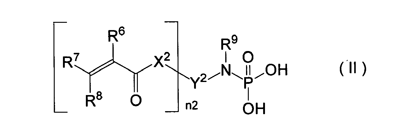

- Lithografie-Druckplattenvorläufer gemäss Anspruch 1, wobei der Lithografie-Druckplattenvorläufer ferner eine Haftschicht zwischen der bildgebenden Schicht und dem hydrophilen Träger umfasst, und die Haftschicht die Verbindung, enthaltend die mindestens eine funktionelle Gruppe mit Wechselwirkung zu der Oberfläche des hydrophilen Trägers, umfasst.
- Lithografie-Druckplattenvorläufer gemäss Anspruch 1 oder Anspruch 2, wobei die bildgebende Schicht ferner einen Infrarotabsorber enthält.
- Lithografie-Druckplattenvorläufer gemäss Anspruch 1, wobei die bildgebende Schicht in der Lage ist, durch eine Drucktinte und/oder eine Anfeuchtlösung entfernt zu werden.
- Lithografie-Druckplattenvorläufer gemäss Anspruch 1, wobei der hydrophile Träger ein Aluminiumträger ist.
- Lithografie-Druckplattenvorläufer gemäss Anspruch 1, wobei der hydrophile Träger ein Silicat-behandelter Aluminiumträger ist; der Lithografie-Druckplattenvorläufer keine alkalische Entwicklung benötigt; und die polymerisierbare Verbindung eine Verbindung, enthaltend mindestens eine funktionelle Gruppe mit Wechselwirkung zu der Oberfläche des Silicat-behandelten Aluminiumträgers umfasst.
- Lithografie-Druckplattenvorläufer gemäss Anspruch 6, wobei die polymerisierbare Verbindung in einer Mikrokapsel eingekapselt ist.
- Lithografie-Druckplattenvorläufer gemäss Anspruch 7, wobei die polymerisierbare Verbindung mindestens zwei polymerisierbare Gruppen in einem Molekül enthält.
- Druckverfahren, umfassend die Schritte:Befestigen eines Lithografie-Druckplattenvorläufers, umfassend eine bildgebende Schicht, enthaltend einen Polymerisationsinitiator und eine polymerisierbare Verbindung, und einen hydrophilen Träger, wobei der Lithografie-Druckplattenvorläufer eine Verbindung, enthaltend mindestens eine funktionelle Gruppe mit Wechselwirkung zu der Oberfläche des hydrophilen Trägers, umfasst, ausgewählt aus den Formeln (I), (II) und (III), auf einer Druckvorrichtung, und bildweise Belichtung des befestigten Lithografie-Druckplattenvorläufer mit einem Laser, oderbildweise Belichtung des Lithografie-Druckplattenvorläufers mit einem Laser und Befestigen des belichteten Lithografie-Druckplattenvorläufers auf der Druckvorrichtung;Zuführen von Drucktinte und/oder einer Anfeuchtlösung zu dem Lithografie-Druckplattenvorläufer;Entfernen der nicht-belichteten Bereiche der bildgebenden Schicht mit der Drucktinte und/oder der Anfeuchtlösung; undDrucken;


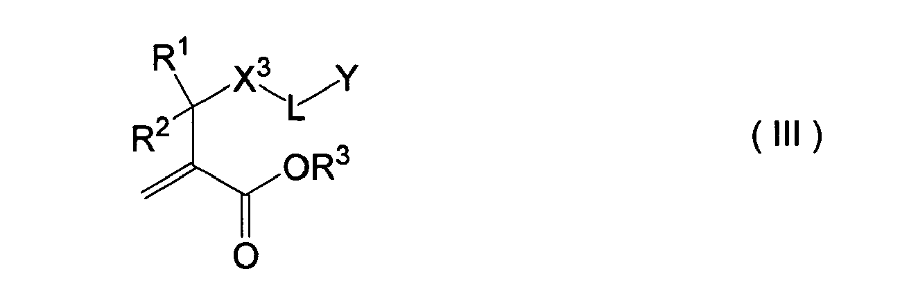 worin R1, R2, R3, R4, R5, R6, R7, R8 und R9 jeweils unabhängig voneinander ein Wasserstoffatom, ein Halogenatom oder eine Alkylgruppe darstellen; X1, X2 und X3 jeweils unabhängig voneinander ein Sauerstoffatom, ein Schwefelatom oder eine Iminogruppe (-NH-) darstellen; Y1 eine Kombination einer zweiwertigen bis dreiwertigen aliphatischen Gruppe, einer zweiwertigen bis vierwertigen aromatischen Gruppe oder einer zweiwertigen bis vierwertigen heterocyclischen Gruppe und einem Sauerstoffatom (-O-), Schwefelatom (-S-), Imino (-NH-) oder Carbonyl (-CO-) darstellt; Y2 eine Verbindungsgruppe mit einer Wertigkeit von (n2 + 1) darstellt; n1 und n2 jeweils unabhängig voneinander eine Zahl von 1, 2 oder 3 darstellen; L eine zweiwertige Verbindungsgruppe darstellt; und Y eine Träger-adsorbierende Gruppe darstellt.
 - Druckverfahren gemäss Anspruch 9, wobei der Lithografie-Druckplattenvorläufer ferner eine Haftschicht zwischen der bildgebenden Schicht und dem hydrophilen Träger umfasst, und die Haftschicht die Verbindung, enthaltend die mindestens eine funktionelle Gruppe mit Wechselwirkung zu der Oberfläche des hydrophilen Trägers, umfasst.
Applications Claiming Priority (8)
| Application Number | Priority Date | Filing Date | Title |
|---|---|---|---|
| JP2003277448 | 2003-07-22 | ||
| JP2003277448 | 2003-07-22 | ||
| JP2004000652 | 2004-01-05 | ||
| JP2004000652 | 2004-01-05 | ||
| JP2004017599 | 2004-01-26 | ||
| JP2004017599 | 2004-01-26 | ||
| JP2004214190 | 2004-07-22 | ||
| JP2004214190A JP2005238816A (ja) | 2003-07-22 | 2004-07-22 | 平版印刷版原版および平版印刷方法 |
Publications (3)
| Publication Number | Publication Date |
|---|---|
| EP1500498A2 EP1500498A2 (de) | 2005-01-26 |
| EP1500498A3 EP1500498A3 (de) | 2005-10-12 |
| EP1500498B1 true EP1500498B1 (de) | 2010-12-15 |
Family
ID=33494222
Family Applications (1)
| Application Number | Title | Priority Date | Filing Date |
|---|---|---|---|
| EP04017306A Expired - Lifetime EP1500498B1 (de) | 2003-07-22 | 2004-07-22 | Flachdruckplattenvorläufer und lithographisches Druckverfahren |
Country Status (5)
| Country | Link |
|---|---|
| US (1) | US7183038B2 (de) |
| EP (1) | EP1500498B1 (de) |
| JP (1) | JP2005238816A (de) |
| AT (1) | ATE491968T1 (de) |
| DE (1) | DE602004030519D1 (de) |
Families Citing this family (155)
| Publication number | Priority date | Publication date | Assignee | Title |
|---|---|---|---|---|
| JP4418714B2 (ja) * | 2003-07-10 | 2010-02-24 | 富士フイルム株式会社 | 平版印刷版原版及び平版印刷方法 |
| JP4644458B2 (ja) * | 2003-09-30 | 2011-03-02 | 富士フイルム株式会社 | 平版印刷版原版および平版印刷方法 |
| ATE357450T1 (de) * | 2003-12-23 | 2007-04-15 | Dentsply Detrey Gmbh | In einem selbstätzendes, selbstgrundierendes dentales haftmittel |
| JP4413069B2 (ja) | 2004-04-28 | 2010-02-10 | 富士フイルム株式会社 | 平版印刷原版および平版印刷方法 |
| EP1614541A3 (de) | 2004-07-08 | 2006-06-07 | Agfa-Gevaert | Verfahren zur Herstellung einer lithographischen Druckplatte |
| JP4411168B2 (ja) | 2004-09-24 | 2010-02-10 | 富士フイルム株式会社 | 感光性平版印刷版 |
| JP4792326B2 (ja) * | 2005-07-25 | 2011-10-12 | 富士フイルム株式会社 | 平版印刷版の作製方法および平版印刷版原版 |
| EP1940620B1 (de) * | 2005-10-20 | 2009-01-28 | Agfa Graphics Nv | Negativ arbeitender, wärmeempfindlicher lithografiedruckplattenvorläufer |
| DE602005012590D1 (de) | 2005-11-18 | 2009-03-19 | Agfa Graphics Nv | Verfahren zur Herstellung einer Lithografiedruckform |
| PL1788442T3 (pl) | 2005-11-18 | 2011-01-31 | Agfa Graphics Nv | Sposób wytwarzania litograficznej formy drukowej |
| PL1788443T3 (pl) | 2005-11-18 | 2014-12-31 | Agfa Nv | Sposób wytwarzania litograficznej płyty drukowej |
| DE602005013398D1 (de) | 2005-11-18 | 2009-04-30 | Agfa Graphics Nv | Verfahren zur Herstellung einer Lithografiedruckform |
| EP1952201B1 (de) | 2005-11-18 | 2011-01-12 | Agfa Graphics N.V. | Verfahren zur herstellung einer fotopolymer-druckplatte |
| DE602005013536D1 (de) * | 2005-11-18 | 2009-05-07 | Agfa Graphics Nv | Verfahren zur Herstellung einer Lithografiedruckform |
| ES2357364T3 (es) * | 2005-11-18 | 2011-04-25 | Agfa Graphics N.V. | Método de elaboración de una plancha de impresión de fotopolímeros. |
| EP1788441B1 (de) | 2005-11-18 | 2010-07-07 | Agfa Graphics N.V. | Verfahren zur Herstellung einer Lithografiedruckform |
| PL1788450T3 (pl) | 2005-11-18 | 2009-07-31 | Agfa Nv | Sposób wytwarzania kliszy do druku litograficznego |
| EP1788444B1 (de) | 2005-11-18 | 2011-01-26 | Agfa Graphics N.V. | Verfahren zur Herstellung einer Lithografiedruckform |
| ATE426191T1 (de) | 2005-11-18 | 2009-04-15 | Agfa Graphics Nv | Verfahren zur herstellung einer lithographischen druckplatte |
| DE602005014249D1 (de) | 2005-11-21 | 2009-06-10 | Agfa Graphics Nv | Verfahren zur Herstellung einer Lithografiedruckform |
| PL1788435T3 (pl) | 2005-11-21 | 2013-09-30 | Agfa Nv | Sposób wytwarzania litograficznej płyty drukowej |
| EP1788449A1 (de) | 2005-11-21 | 2007-05-23 | Agfa Graphics N.V. | Verfahren zur Herstellung einer Lithografiedruckform |
| US20080008957A1 (en) * | 2006-06-27 | 2008-01-10 | Eastman Kodak Company | Negative-working radiation-sensitive compositions and imageable elements |
| CN101681106B (zh) | 2007-05-25 | 2013-11-20 | 爱克发印艺公司 | 平版印刷印版前体、制备前体中敏化剂混合物的方法 |
| US8415087B2 (en) | 2007-11-16 | 2013-04-09 | Agfa Graphics Nv | Method of making a lithographic printing plate |
| JP2009258705A (ja) | 2008-03-25 | 2009-11-05 | Fujifilm Corp | 平版印刷版原版 |
| JP5265955B2 (ja) * | 2008-04-18 | 2013-08-14 | 富士フイルム株式会社 | 平版印刷版用アルミニウム合金板、平版印刷版用支持体、平版印刷版用原版および平版印刷版用アルミニウム合金板の製造方法 |
| EP2186637B1 (de) | 2008-10-23 | 2012-05-02 | Agfa Graphics N.V. | Lithographiedruckplatte |
| JP5449866B2 (ja) | 2009-05-29 | 2014-03-19 | 富士フイルム株式会社 | 平版印刷版原版及び平版印刷版の作製方法 |
| JP5586333B2 (ja) | 2009-06-09 | 2014-09-10 | 富士フイルム株式会社 | 平版印刷版の作製方法 |
| JP5346755B2 (ja) | 2009-09-24 | 2013-11-20 | 富士フイルム株式会社 | 平版印刷版の作製方法 |
| US8883401B2 (en) | 2009-09-24 | 2014-11-11 | Fujifilm Corporation | Lithographic printing original plate |
| JP2011090295A (ja) | 2009-09-24 | 2011-05-06 | Fujifilm Corp | 平版印刷版の作製方法 |
| JP2011090294A (ja) | 2009-09-24 | 2011-05-06 | Fujifilm Corp | 平版印刷版の作製方法 |
| JP2011148292A (ja) | 2009-12-25 | 2011-08-04 | Fujifilm Corp | 平版印刷版原版及びその製版方法 |
| JP5541913B2 (ja) | 2009-12-25 | 2014-07-09 | 富士フイルム株式会社 | 平版印刷版の作製方法 |
| JP2011154367A (ja) | 2009-12-28 | 2011-08-11 | Fujifilm Corp | 平版印刷版の作製方法 |
| JP5624880B2 (ja) | 2009-12-28 | 2014-11-12 | 富士フイルム株式会社 | 平版印刷版原版及び平版印刷版の作製方法 |
| JP5322963B2 (ja) | 2010-01-29 | 2013-10-23 | 富士フイルム株式会社 | 平版印刷版原版及び平版印刷版の作製方法 |
| JP5537980B2 (ja) | 2010-02-12 | 2014-07-02 | 富士フイルム株式会社 | 平版印刷版原版及びその製版方法 |
| JP5346845B2 (ja) | 2010-02-26 | 2013-11-20 | 富士フイルム株式会社 | 平版印刷版の作製方法及び平版印刷版原版用現像液 |
| JP5525873B2 (ja) | 2010-03-15 | 2014-06-18 | 富士フイルム株式会社 | 平版印刷版の作製方法 |
| WO2011115125A1 (ja) | 2010-03-19 | 2011-09-22 | 富士フイルム株式会社 | 発色感光性組成物、平版印刷版原版及びその製版方法 |
| JP2011221522A (ja) | 2010-03-26 | 2011-11-04 | Fujifilm Corp | 平版印刷版の作製方法 |
| AU2011236976B2 (en) | 2010-03-31 | 2014-08-14 | Fujifilm Corporation | Developer for processing planographic printing plate precursor, method for preparing planographic printing plate using the developer, and method for printing |
| EP2383118B1 (de) | 2010-04-30 | 2013-10-16 | Fujifilm Corporation | Lithographiedruckplattenvorläufer und Plattenherstellungsverfahren damit |
| WO2012026265A1 (ja) | 2010-08-27 | 2012-03-01 | 富士フイルム株式会社 | 機上現像型平版印刷版原版及びそれを用いる製版方法 |
| JP2012073595A (ja) | 2010-08-31 | 2012-04-12 | Fujifilm Corp | 平版印刷版の作製方法 |
| JP5789448B2 (ja) | 2010-08-31 | 2015-10-07 | 富士フイルム株式会社 | 平版印刷版原版及びその製版方法 |
| JP2012073594A (ja) | 2010-08-31 | 2012-04-12 | Fujifilm Corp | 平版印刷版の作製方法 |
| WO2012033138A1 (ja) * | 2010-09-09 | 2012-03-15 | Jsr株式会社 | 感放射線性樹脂組成物、重合体及び化合物 |
| JP5656784B2 (ja) | 2010-09-24 | 2015-01-21 | 富士フイルム株式会社 | 重合性組成物及びそれを用いた平版印刷版原版、並びに平版印刷方法 |
| JP5205505B2 (ja) | 2010-12-28 | 2013-06-05 | 富士フイルム株式会社 | 平版印刷版原版及びその平版印刷方法 |
| JP5211187B2 (ja) | 2011-02-28 | 2013-06-12 | 富士フイルム株式会社 | 平版印刷版原版及び製版方法 |
| JP5244987B2 (ja) | 2011-02-28 | 2013-07-24 | 富士フイルム株式会社 | 平版印刷版原版及びその製版方法 |
| JP5186574B2 (ja) | 2011-02-28 | 2013-04-17 | 富士フイルム株式会社 | 平版印刷版原版及びその製版方法 |
| JP5705969B2 (ja) | 2011-03-28 | 2015-04-22 | 富士フイルム株式会社 | 平版印刷版の製版方法 |
| JP5514781B2 (ja) | 2011-08-31 | 2014-06-04 | 富士フイルム株式会社 | 平版印刷版原版及びこれを用いた平版印刷版の作成方法 |
| JP5401522B2 (ja) | 2011-09-15 | 2014-01-29 | 富士フイルム株式会社 | コーティング組成物、ならびに該組成物を用いた、画像形成材料、平版印刷版原版及び酸素遮断性フィルム |
| WO2013047229A1 (ja) | 2011-09-26 | 2013-04-04 | 富士フイルム株式会社 | 平版印刷版の製版方法 |
| CN103827749B (zh) | 2011-09-26 | 2018-06-15 | 富士胶片株式会社 | 平版印刷版的制版方法 |
| JP5690696B2 (ja) | 2011-09-28 | 2015-03-25 | 富士フイルム株式会社 | 平版印刷版の製版方法 |
| JP5604398B2 (ja) | 2011-09-30 | 2014-10-08 | 富士フイルム株式会社 | 平版印刷版原版及び平版印刷版の作製方法 |
| JP5463346B2 (ja) | 2011-12-26 | 2014-04-09 | 富士フイルム株式会社 | 平版印刷版の製版方法 |
| WO2013125315A1 (ja) | 2012-02-20 | 2013-08-29 | 富士フイルム株式会社 | 製版処理廃液の濃縮方法およびリサイクル方法 |
| JP5771738B2 (ja) | 2012-02-23 | 2015-09-02 | 富士フイルム株式会社 | 発色性組成物、発色性硬化組成物、平版印刷版原版及び製版方法、並びに発色性化合物 |
| JP5711168B2 (ja) | 2012-02-27 | 2015-04-30 | 富士フイルム株式会社 | 平版印刷版原版および平版印刷版の作製方法 |
| JP5715975B2 (ja) | 2012-02-29 | 2015-05-13 | 富士フイルム株式会社 | 平版印刷版原版および平版印刷版の製造方法 |
| JP6081458B2 (ja) | 2012-06-29 | 2017-02-15 | 富士フイルム株式会社 | 現像処理廃液濃縮方法及び現像処理廃液のリサイクル方法 |
| WO2014021622A1 (ko) * | 2012-08-02 | 2014-02-06 | 동우화인켐 주식회사 | 점착제 조성물 |
| CN104619512A (zh) | 2012-09-20 | 2015-05-13 | 富士胶片株式会社 | 平版印刷版原版及制版方法 |
| BR112015006578A2 (pt) | 2012-09-26 | 2019-12-17 | Fujifilm Corp | precursor da chapa de impressão litográfica e método de fabricação da chapa |
| JP5786099B2 (ja) | 2012-09-26 | 2015-09-30 | 富士フイルム株式会社 | 平版印刷版原版及び平版印刷版の製版方法 |
| EP2755088B1 (de) | 2013-01-11 | 2016-07-27 | Agfa Graphics NV | Verfahren zur Herstellung einer Flachdruckplatte |
| EP2963495B1 (de) | 2013-02-27 | 2019-06-05 | FUJIFILM Corporation | Infrarotempfindliche chromogene zusammensetzung, infrarothärtbare chromogene zusammensetzung, lithografiedruckplattenvorläufer und plattenherstellungsverfahren |
| ES2683883T3 (es) * | 2013-06-20 | 2018-09-28 | Ivoclar Vivadent Ag | Ácidos ß-cetofosfónicos y materiales dentales a base de los mismos |
| WO2015050767A1 (en) * | 2013-10-03 | 2015-04-09 | 3M Innovative Properties Company | Ligand-functionalized substrates with enhanced binding capacity |
| JP6271594B2 (ja) | 2014-01-31 | 2018-01-31 | 富士フイルム株式会社 | 赤外線感光性発色組成物、平版印刷版原版、平版印刷版の製版方法、及び、赤外線感光性発色剤 |
| WO2015119089A1 (ja) | 2014-02-04 | 2015-08-13 | 富士フイルム株式会社 | 平版印刷版原版及びその製造方法、平版印刷版の製版方法、並びに、印刷方法 |
| EP2916171B1 (de) | 2014-03-03 | 2017-05-31 | Agfa Graphics Nv | Verfahren zum Herstellen eines Lithographiedruckformvorläufers |
| WO2018092661A1 (ja) | 2016-11-16 | 2018-05-24 | 富士フイルム株式会社 | 輻射線感光性組成物、平版印刷版原版、及び、平版印刷版の製版方法 |
| CN110366567A (zh) | 2017-02-28 | 2019-10-22 | 富士胶片株式会社 | 固化性组合物、平版印刷版原版及平版印刷版的制作方法 |
| WO2018159640A1 (ja) | 2017-02-28 | 2018-09-07 | 富士フイルム株式会社 | 硬化性組成物、平版印刷版原版、平版印刷版の作製方法、及び、化合物 |
| JP6934939B2 (ja) | 2017-05-31 | 2021-09-15 | 富士フイルム株式会社 | 平版印刷版原版、及び平版印刷版の作製方法 |
| CN110691701A (zh) | 2017-05-31 | 2020-01-14 | 富士胶片株式会社 | 平版印刷版原版、平版印刷版原版制作用树脂组合物及平版印刷版的制作方法 |
| JP6942799B2 (ja) | 2017-05-31 | 2021-09-29 | 富士フイルム株式会社 | 平版印刷版原版、及び、平版印刷版の作製方法 |
| JP6956787B2 (ja) | 2017-06-12 | 2021-11-02 | 富士フイルム株式会社 | 平版印刷版原版、平版印刷版の製版方法、有機ポリマー粒子、及び、感光性樹脂組成物 |
| JP6832427B2 (ja) | 2017-06-30 | 2021-02-24 | 富士フイルム株式会社 | 平版印刷版原版、及び平版印刷版の作製方法 |
| EP3594009B1 (de) | 2017-07-13 | 2021-04-21 | FUJIFILM Corporation | Originalplatte einer lithographischen druckplatte und verfahren zur herstellung einer lithographischen druckplatte |
| CN110998439B (zh) | 2017-07-25 | 2023-09-19 | 富士胶片株式会社 | 平版印刷版原版、平版印刷版的制作方法及显色组合物 |
| EP3441223B1 (de) | 2017-08-07 | 2024-02-21 | Eco3 Bv | Lithographiedruckplattenvorläufer |
| EP3656575B1 (de) | 2017-08-31 | 2022-09-07 | FUJIFILM Corporation | Lithographische druckplattenoriginalplatte, verfahren zur herstellung einer lithographischen druckplatte und lithographisches druckverfahren |
| EP3474073B1 (de) | 2017-10-17 | 2022-12-07 | Agfa Offset Bv | Methode zur herstellung einer druckplatte |
| ES2881270T3 (es) | 2017-12-08 | 2021-11-29 | Agfa Nv | Procedimiento de fabricación de una plancha de impresión litográfica |
| WO2019151361A1 (ja) | 2018-01-31 | 2019-08-08 | 富士フイルム株式会社 | 平版印刷版原版、及び、平版印刷版の作製方法 |
| CN112533764B (zh) | 2018-07-31 | 2023-05-02 | 富士胶片株式会社 | 平版印刷版原版及其层叠体、平版印刷版的制版方法及平版印刷方法 |
| EP3831614B1 (de) | 2018-07-31 | 2023-09-06 | FUJIFILM Corporation | Flachdruckoriginalplatte, laminatkörper für flachdruckoriginalplatte, plattenherstellungsverfahren für flachdruckplatte und flachdruckverfahren |
| CN112638657A (zh) | 2018-08-31 | 2021-04-09 | 富士胶片株式会社 | 平版印刷版原版、平版印刷版的制作方法、平版印刷方法及固化性组合物 |
| WO2020090996A1 (ja) | 2018-10-31 | 2020-05-07 | 富士フイルム株式会社 | 平版印刷版原版、平版印刷版の作製方法、及び、平版印刷方法 |
| WO2020090995A1 (ja) | 2018-10-31 | 2020-05-07 | 富士フイルム株式会社 | 平版印刷版原版、平版印刷版の作製方法、及び、平版印刷方法 |
| EP3650938A1 (de) | 2018-11-09 | 2020-05-13 | Agfa Nv | Lithographiedruckplattenvorläufer |
| WO2020120402A1 (en) | 2018-12-10 | 2020-06-18 | Agfa Nv | On-press processing of a uv or violet-sensitized lithographic printing plate |
| CN113382870B (zh) | 2019-01-31 | 2023-10-31 | 富士胶片株式会社 | 平版印刷版原版、平版印刷版的制作方法及平版印刷方法 |
| WO2020158288A1 (ja) | 2019-01-31 | 2020-08-06 | 富士フイルム株式会社 | 平版印刷版原版、平版印刷版の作製方法、及び、平版印刷方法 |
| EP3904099B1 (de) | 2019-01-31 | 2024-08-28 | FUJIFILM Corporation | Flachdruckplattenvorläufer, verfahren zur herstellung einer flachdruckplatte und flachdruckverfahren |
| CN113474177B (zh) | 2019-01-31 | 2023-09-19 | 富士胶片株式会社 | 平版印刷版原版、平版印刷版的制作方法及平版印刷方法 |
| EP3991989B1 (de) | 2019-06-28 | 2025-11-05 | FUJIFILM Corporation | Lithografischer druckplattenvorläufer mit entwicklung auf der druckpresse, verfahren zur herstellung einer lithografischen druckplatte und lithografisches druckverfahren |
| CN114144306A (zh) | 2019-06-28 | 2022-03-04 | 富士胶片株式会社 | 机上显影型平版印刷版原版、平版印刷版的制作方法及平版印刷方法 |
| CN120742621A (zh) | 2019-06-28 | 2025-10-03 | 富士胶片株式会社 | 机上显影型平版印刷版原版、平版印刷版的制作方法及平版印刷方法 |
| JP7321261B2 (ja) | 2019-06-28 | 2023-08-04 | 富士フイルム株式会社 | 平版印刷版原版、平版印刷版の作製方法、及び、平版印刷方法 |
| WO2020262685A1 (ja) | 2019-06-28 | 2020-12-30 | 富士フイルム株式会社 | 平版印刷版原版、平版印刷版の作製方法、及び、平版印刷方法 |
| EP3991988B1 (de) | 2019-06-28 | 2025-11-05 | FUJIFILM Corporation | Flachdruckplattenvorläufer, verfahren zur herstellung einer flachdruckplatte und flachdruckverfahren |
| JP7293356B2 (ja) | 2019-06-28 | 2023-06-19 | 富士フイルム株式会社 | 機上現像型平版印刷版原版、平版印刷版の作製方法、及び、平版印刷方法 |
| CN114051454B (zh) | 2019-06-28 | 2023-12-15 | 富士胶片株式会社 | 机上显影型平版印刷版原版、平版印刷版的制作方法及平版印刷方法 |
| JP7408675B2 (ja) | 2019-09-30 | 2024-01-05 | 富士フイルム株式会社 | 平版印刷版原版、平版印刷版の作製方法、及び、平版印刷方法 |
| WO2021065279A1 (ja) | 2019-09-30 | 2021-04-08 | 富士フイルム株式会社 | 平版印刷版原版、平版印刷版の作製方法、及び、平版印刷方法 |
| JP7389128B2 (ja) | 2019-09-30 | 2023-11-29 | 富士フイルム株式会社 | 平版印刷版原版、平版印刷版の作製方法、及び、平版印刷方法 |
| JP7282341B2 (ja) * | 2019-10-16 | 2023-05-29 | 株式会社トクヤマデンタル | 接着性組成物 |
| JP7282651B2 (ja) * | 2019-10-16 | 2023-05-29 | ミヨシ油脂株式会社 | 重合性ホスホン酸系化合物及び接着性組成物 |
| JP7313626B2 (ja) * | 2019-10-16 | 2023-07-25 | 株式会社トクヤマデンタル | 歯科用接着性組成物 |
| EP4082791B1 (de) | 2019-12-27 | 2024-10-16 | FUJIFILM Corporation | Flachdruckverfahren |
| WO2021172453A1 (ja) | 2020-02-28 | 2021-09-02 | 富士フイルム株式会社 | 平版印刷版原版、平版印刷版の作製方法、及び、平版印刷方法 |
| EP4159455B1 (de) | 2020-05-29 | 2025-10-29 | FUJIFILM Corporation | Auf der druckpresse entwickelbarer lithographiedruckplattenvorläufer und verfahren zur herstellung einer lithographischen druckplatte |
| CN115666960B (zh) | 2020-05-29 | 2025-11-25 | 富士胶片株式会社 | 层叠体 |
| WO2021241519A1 (ja) | 2020-05-29 | 2021-12-02 | 富士フイルム株式会社 | 機上現像型平版印刷版原版、平版印刷版の作製方法、及び平版印刷方法 |
| EP4159456B1 (de) | 2020-05-29 | 2026-03-11 | FUJIFILM Corporation | Lithografiedruckplattenvorläufer mit entwicklung auf der druckpresse, lithografiedruckplattenherstellungsverfahren und lithografiedruckverfahren |
| EP4159459B1 (de) | 2020-05-29 | 2025-12-17 | FUJIFILM Corporation | Lithografiedruckplattenvorläufer mit entwicklung auf der druckpresse, lithografiedruckplattenherstellungsverfahren und lithografiedruckverfahren |
| JP7413526B2 (ja) | 2020-05-29 | 2024-01-15 | 富士フイルム株式会社 | 機上現像型平版印刷版原版、平版印刷版の作製方法、及び、平版印刷方法 |
| EP4159441B1 (de) | 2020-05-29 | 2026-01-28 | FUJIFILM Corporation | Auf der druckpresse entwickelbarer negativ arbeitender lithographischer druckplattenvorläufer, verfahren zur herstellung einer lithographischen druckplatte und lithographisches druckverfahren |
| EP3922462B1 (de) | 2020-06-08 | 2023-03-01 | Agfa Offset Bv | Lithografischer photopolymerer druckplattenvorläufer mit verbesserter tageslichtstabilität |
| WO2021256341A1 (ja) | 2020-06-17 | 2021-12-23 | 富士フイルム株式会社 | 機上現像型平版印刷版原版、平版印刷版の作製方法、及び、平版印刷方法 |
| JP7528223B2 (ja) | 2020-07-21 | 2024-08-05 | 富士フイルム株式会社 | 機上現像型平版印刷版原版、平版印刷版の作製方法、及び、平版印刷方法 |
| EP4190581A4 (de) | 2020-07-31 | 2024-01-24 | FUJIFILM Corporation | Auf der druckpresse entwicklungsfähige flachdruckoriginalplatte, verfahren zur herstellung einer flachdruckplatte und flachdruckverfahren |
| EP3960455B1 (de) | 2020-08-31 | 2025-08-06 | Eco3 Bv | Lithografiedruckplattenvorläufer, verfahren zur herstellung eines lithografiedruckplattenvorläufers und verfahren zur herstellung einer lithografiedruckplatte |
| US12403686B2 (en) | 2020-10-09 | 2025-09-02 | Eco3 Bv | Lithographic printing plate precursor |
| US11813884B2 (en) | 2020-12-17 | 2023-11-14 | Eastman Kodak Company | Lithographic printing plate precursors and method of use |
| CN116615339B (zh) * | 2020-12-17 | 2025-10-10 | 伊斯曼柯达公司 | 平版印刷版前体和使用方法 |
| WO2022138880A1 (ja) | 2020-12-25 | 2022-06-30 | 富士フイルム株式会社 | ネガ型平版印刷版原版の積層体、及びネガ型平版印刷版の作製方法 |
| WO2022163777A1 (ja) | 2021-01-28 | 2022-08-04 | 富士フイルム株式会社 | 機上現像型平版印刷版原版、平版印刷版の作製方法、及び、平版印刷方法 |
| JP7726979B2 (ja) | 2021-02-26 | 2025-08-20 | 富士フイルム株式会社 | 機上現像型平版印刷版原版、平版印刷版の作製方法、平版印刷方法、及び、呈色剤 |
| EP4129682B1 (de) | 2021-08-05 | 2025-10-01 | Eco3 Bv | Lithografiedruckplattenvorläufer |
| EP4397501A4 (de) | 2021-08-31 | 2024-11-20 | FUJIFILM Corporation | Auf der druckpresse entwickelbare originalflachdruckplatte, verfahren zur herstellung einer lithografiedruckplatte und lithografiedruckverfahren |
| EP4397502A4 (de) | 2021-08-31 | 2024-11-27 | FUJIFILM Corporation | Lithographischer druckplattenvorläufer mit entwicklung auf einer maschine und verfahren zur herstellung einer druckplatte |
| JPWO2023032681A1 (de) | 2021-08-31 | 2023-03-09 | ||
| WO2023145972A1 (ja) | 2022-01-31 | 2023-08-03 | 富士フイルム株式会社 | 機上現像型平版印刷版原版、平版印刷版の作製方法、平版印刷方法、及び、積層体 |
| EP4245542B1 (de) | 2022-03-18 | 2025-12-10 | FUJIFILM Corporation | Lithografiedruckplattenvorläufer, verfahren zur herstellung einer lithografiedruckplatte und lithografiedruckverfahren |
| CN119968276A (zh) | 2022-09-30 | 2025-05-09 | 富士胶片株式会社 | 机上显影型平版印刷版原版、平版印刷版的制作方法及平版印刷方法 |
| JP2024062746A (ja) | 2022-10-25 | 2024-05-10 | 富士フイルム株式会社 | 平版印刷版原版、平版印刷版の作製方法、及び、平版印刷方法 |
| CN120282886A (zh) | 2022-11-30 | 2025-07-08 | 富士胶片株式会社 | 平版印刷版原版、平版印刷版的制作方法及平版印刷方法 |
| JP2024143725A (ja) | 2023-03-30 | 2024-10-11 | 富士フイルム株式会社 | 機上現像型平版印刷版原版、平版印刷版の作製方法、及び、平版印刷方法 |
| JP2024143724A (ja) | 2023-03-30 | 2024-10-11 | 富士フイルム株式会社 | 機上現像型平版印刷版原版、平版印刷版の作製方法、平版印刷方法、及び化合物 |
| WO2025013922A1 (ja) | 2023-07-11 | 2025-01-16 | 富士フイルム株式会社 | 機上現像型平版印刷版原版、平版印刷版の作製方法、及び平版印刷方法 |
| CN121568847A (zh) | 2023-07-11 | 2026-02-24 | 富士胶片株式会社 | 机上显影型平版印刷版原版、平版印刷版的制作方法、平版印刷方法及化合物 |
| WO2025047939A1 (ja) | 2023-08-31 | 2025-03-06 | 富士フイルム株式会社 | 機上現像型平版印刷版原版、及び印刷版の作製方法 |
| JP2025132837A (ja) | 2024-02-29 | 2025-09-10 | 富士フイルム株式会社 | 機上現像型平版印刷版原版、平版印刷版の作製方法、平版印刷方法、及び化合物 |
Family Cites Families (20)
| Publication number | Priority date | Publication date | Assignee | Title |
|---|---|---|---|---|
| US4539382A (en) * | 1981-07-29 | 1985-09-03 | Kuraray Co., Ltd. | Adhesive composition |
| DE4102173A1 (de) * | 1991-01-25 | 1992-07-30 | Basf Ag | Lagerstabile loesung eines carboxylgruppenhaltigen copolymerisats sowie verfahren zur herstellung von photoempfindlichen lacken und offsetdruckplatten |
| DE69517174T2 (de) | 1995-10-24 | 2000-11-09 | Agfa-Gevaert N.V., Mortsel | Verfahren zur Herstellung einer lithographische Druckplatte mit auf der Druckpresse stattfindenden Entwicklung |
| US5800965A (en) * | 1996-02-29 | 1998-09-01 | Mitsubishi Chemical Corporation | Photopolymerizable composition for a photosensitive lithographic printing plate and photosensitive lithographic printing plate employing it |
| JP3275809B2 (ja) * | 1996-12-26 | 2002-04-22 | 三菱化学株式会社 | 感光性平版印刷版 |
| US6514668B1 (en) | 1996-12-26 | 2003-02-04 | Mitsubishi Chemical Corporation | Photosensitive lithographic printing plate |
| JPH10260536A (ja) * | 1997-03-21 | 1998-09-29 | Konica Corp | 感光性平版印刷版 |
| US6558875B1 (en) * | 1999-07-27 | 2003-05-06 | Mitsubishi Chemical Corporation | Method for treating photosensitive lithographic printing plate |
| US6558873B1 (en) | 1999-10-05 | 2003-05-06 | Fuji Photo Film Co., Ltd. | Lithographic printing plate precursor |
| JP2001277740A (ja) | 2000-01-27 | 2001-10-10 | Fuji Photo Film Co Ltd | 平版印刷版用原版 |
| JP2001277742A (ja) | 2000-01-27 | 2001-10-10 | Fuji Photo Film Co Ltd | 平版印刷版用原版 |
| JP2002069110A (ja) * | 2000-09-01 | 2002-03-08 | Fuji Photo Film Co Ltd | 光重合性組成物 |
| JP4266077B2 (ja) | 2001-03-26 | 2009-05-20 | 富士フイルム株式会社 | 平版印刷版原版及び平版印刷方法 |
| JP4199942B2 (ja) * | 2001-07-09 | 2008-12-24 | 富士フイルム株式会社 | 平版印刷版の製版方法 |
| JP2004117893A (ja) * | 2002-09-26 | 2004-04-15 | Fuji Photo Film Co Ltd | 平版印刷版原版 |
| DE10255663B4 (de) | 2002-11-28 | 2006-05-04 | Kodak Polychrome Graphics Gmbh | Strahlungsempfindliche Elemente |
| JP4040476B2 (ja) * | 2003-01-14 | 2008-01-30 | 富士フイルム株式会社 | 感光性平版印刷版 |
| DE602004009846T2 (de) * | 2003-03-20 | 2008-08-28 | Fujifilm Corp. | Flachdruckplattenvorläufer |
| EP1464486B1 (de) | 2003-03-26 | 2009-06-17 | FUJIFILM Corporation | Flachdruckverfahren und vorsensibilisierte Platte |
| JP4418714B2 (ja) | 2003-07-10 | 2010-02-24 | 富士フイルム株式会社 | 平版印刷版原版及び平版印刷方法 |
-
2004
- 2004-07-22 EP EP04017306A patent/EP1500498B1/de not_active Expired - Lifetime
- 2004-07-22 US US10/896,070 patent/US7183038B2/en not_active Expired - Lifetime
- 2004-07-22 DE DE602004030519T patent/DE602004030519D1/de not_active Expired - Lifetime
- 2004-07-22 JP JP2004214190A patent/JP2005238816A/ja active Pending
- 2004-07-22 AT AT04017306T patent/ATE491968T1/de not_active IP Right Cessation
Also Published As
| Publication number | Publication date |
|---|---|
| US20050048398A1 (en) | 2005-03-03 |
| JP2005238816A (ja) | 2005-09-08 |
| DE602004030519D1 (de) | 2011-01-27 |
| ATE491968T1 (de) | 2011-01-15 |
| EP1500498A3 (de) | 2005-10-12 |
| US7183038B2 (en) | 2007-02-27 |
| EP1500498A2 (de) | 2005-01-26 |
Similar Documents
| Publication | Publication Date | Title |
|---|---|---|
| EP1500498B1 (de) | Flachdruckplattenvorläufer und lithographisches Druckverfahren | |
| EP1759836B1 (de) | Lithographischer Druckplattenvorläufer und lithographische Druckmethode | |
| EP1520694B1 (de) | Flachdruckplattenvorläufer und Flachdruckverfahren | |
| EP1669194B1 (de) | Flachdruckplattenvorläufer und Verfahren zur Herstellung einer Druckplatte | |
| JP4418714B2 (ja) | 平版印刷版原版及び平版印刷方法 | |
| US7338741B2 (en) | Lithographic printing plate precursor and lithographic printing method | |
| JP2006239867A (ja) | 平版印刷版原版および平版印刷方法 | |
| EP1695822B1 (de) | Flachdruckplattenvorläufer und lithographisches Druckverfahren | |
| US7704671B2 (en) | Lithographic printing plate precursor and lithographic printing method | |
| US7419758B2 (en) | Lithographic printing plate precursor and lithographic printing method | |
| EP1561577B1 (de) | Flachdruckplattenvorläuferstapel | |
| JP2005319758A (ja) | 平版印刷方法及びそれに用いる平版印刷版原版 | |
| JP2006001144A (ja) | 平版印刷方法及びそれに用いる平版印刷版原版 | |
| JP4431326B2 (ja) | 平版印刷版原版および平版印刷方法 | |
| JP2006239860A (ja) | 平版印刷版原版および平版印刷方法 | |
| JP2006264333A (ja) | 平版印刷版原版および平版印刷方法 | |
| JP4542931B2 (ja) | 平版印刷版原版および平版印刷方法 | |
| JP4542932B2 (ja) | 平版印刷版原版および平版印刷方法 | |
| JP2005059283A (ja) | 平版印刷版原版及び平版印刷方法 | |
| JP2005103968A (ja) | 平版印刷版原版および平版印刷方法 | |
| JP2005271471A (ja) | 平版印刷方法及びそれに用いる平版印刷版原版 | |
| JP2006102947A (ja) | 平版印刷版原版および平版印刷方法 | |
| JP2004358897A (ja) | 平版印刷版原版および平版印刷方法 | |
| JP2005059445A (ja) | 平版印刷版原版及び平版印刷方法 | |
| JP2005059467A (ja) | 平版印刷版原版 |
Legal Events
| Date | Code | Title | Description |
|---|---|---|---|
| PUAI | Public reference made under article 153(3) epc to a published international application that has entered the european phase |
Free format text: ORIGINAL CODE: 0009012 |
|
| AK | Designated contracting states |
Kind code of ref document: A2 Designated state(s): AT BE BG CH CY CZ DE DK EE ES FI FR GB GR HU IE IT LI LU MC NL PL PT RO SE SI SK TR |
|
| AX | Request for extension of the european patent |
Extension state: AL HR LT LV MK |
|
| PUAL | Search report despatched |
Free format text: ORIGINAL CODE: 0009013 |
|
| AK | Designated contracting states |
Kind code of ref document: A3 Designated state(s): AT BE BG CH CY CZ DE DK EE ES FI FR GB GR HU IE IT LI LU MC NL PL PT RO SE SI SK TR |
|
| AX | Request for extension of the european patent |
Extension state: AL HR LT LV MK |
|
| RIC1 | Information provided on ipc code assigned before grant |
Ipc: 7G 03F 7/11 B Ipc: 7B 41C 1/10 B Ipc: 7G 03F 7/027 A |
|
| 17P | Request for examination filed |
Effective date: 20051212 |
|
| AKX | Designation fees paid |
Designated state(s): AT BE BG CH CY CZ DE DK EE ES FI FR GB GR HU IE IT LI LU MC NL PL PT RO SE SI SK TR |
|
| RAP1 | Party data changed (applicant data changed or rights of an application transferred) |
Owner name: FUJIFILM CORPORATION |
|
| 17Q | First examination report despatched |
Effective date: 20071017 |
|
| GRAP | Despatch of communication of intention to grant a patent |
Free format text: ORIGINAL CODE: EPIDOSNIGR1 |
|
| GRAS | Grant fee paid |
Free format text: ORIGINAL CODE: EPIDOSNIGR3 |
|
| GRAA | (expected) grant |
Free format text: ORIGINAL CODE: 0009210 |
|
| AK | Designated contracting states |
Kind code of ref document: B1 Designated state(s): AT BE BG CH CY CZ DE DK EE ES FI FR GB GR HU IE IT LI LU MC NL PL PT RO SE SI SK TR |
|
| REG | Reference to a national code |
Ref country code: CH Ref legal event code: EP Ref country code: GB Ref legal event code: FG4D |
|
| REG | Reference to a national code |
Ref country code: IE Ref legal event code: FG4D |
|
| REF | Corresponds to: |
Ref document number: 602004030519 Country of ref document: DE Date of ref document: 20110127 Kind code of ref document: P |
|
| REG | Reference to a national code |
Ref country code: NL Ref legal event code: VDEP Effective date: 20101215 |
|
| PG25 | Lapsed in a contracting state [announced via postgrant information from national office to epo] |
Ref country code: AT Free format text: LAPSE BECAUSE OF FAILURE TO SUBMIT A TRANSLATION OF THE DESCRIPTION OR TO PAY THE FEE WITHIN THE PRESCRIBED TIME-LIMIT Effective date: 20101215 Ref country code: CY Free format text: LAPSE BECAUSE OF FAILURE TO SUBMIT A TRANSLATION OF THE DESCRIPTION OR TO PAY THE FEE WITHIN THE PRESCRIBED TIME-LIMIT Effective date: 20101215 Ref country code: SE Free format text: LAPSE BECAUSE OF FAILURE TO SUBMIT A TRANSLATION OF THE DESCRIPTION OR TO PAY THE FEE WITHIN THE PRESCRIBED TIME-LIMIT Effective date: 20101215 Ref country code: NL Free format text: LAPSE BECAUSE OF FAILURE TO SUBMIT A TRANSLATION OF THE DESCRIPTION OR TO PAY THE FEE WITHIN THE PRESCRIBED TIME-LIMIT Effective date: 20101215 Ref country code: FI Free format text: LAPSE BECAUSE OF FAILURE TO SUBMIT A TRANSLATION OF THE DESCRIPTION OR TO PAY THE FEE WITHIN THE PRESCRIBED TIME-LIMIT Effective date: 20101215 Ref country code: SI Free format text: LAPSE BECAUSE OF FAILURE TO SUBMIT A TRANSLATION OF THE DESCRIPTION OR TO PAY THE FEE WITHIN THE PRESCRIBED TIME-LIMIT Effective date: 20101215 Ref country code: BG Free format text: LAPSE BECAUSE OF FAILURE TO SUBMIT A TRANSLATION OF THE DESCRIPTION OR TO PAY THE FEE WITHIN THE PRESCRIBED TIME-LIMIT Effective date: 20110315 |
|
| PG25 | Lapsed in a contracting state [announced via postgrant information from national office to epo] |
Ref country code: CZ Free format text: LAPSE BECAUSE OF FAILURE TO SUBMIT A TRANSLATION OF THE DESCRIPTION OR TO PAY THE FEE WITHIN THE PRESCRIBED TIME-LIMIT Effective date: 20101215 Ref country code: GR Free format text: LAPSE BECAUSE OF FAILURE TO SUBMIT A TRANSLATION OF THE DESCRIPTION OR TO PAY THE FEE WITHIN THE PRESCRIBED TIME-LIMIT Effective date: 20110316 Ref country code: ES Free format text: LAPSE BECAUSE OF FAILURE TO SUBMIT A TRANSLATION OF THE DESCRIPTION OR TO PAY THE FEE WITHIN THE PRESCRIBED TIME-LIMIT Effective date: 20110326 Ref country code: EE Free format text: LAPSE BECAUSE OF FAILURE TO SUBMIT A TRANSLATION OF THE DESCRIPTION OR TO PAY THE FEE WITHIN THE PRESCRIBED TIME-LIMIT Effective date: 20101215 Ref country code: BE Free format text: LAPSE BECAUSE OF FAILURE TO SUBMIT A TRANSLATION OF THE DESCRIPTION OR TO PAY THE FEE WITHIN THE PRESCRIBED TIME-LIMIT Effective date: 20101215 Ref country code: PT Free format text: LAPSE BECAUSE OF FAILURE TO SUBMIT A TRANSLATION OF THE DESCRIPTION OR TO PAY THE FEE WITHIN THE PRESCRIBED TIME-LIMIT Effective date: 20110415 |
|
| PG25 | Lapsed in a contracting state [announced via postgrant information from national office to epo] |
Ref country code: SK Free format text: LAPSE BECAUSE OF FAILURE TO SUBMIT A TRANSLATION OF THE DESCRIPTION OR TO PAY THE FEE WITHIN THE PRESCRIBED TIME-LIMIT Effective date: 20101215 Ref country code: PL Free format text: LAPSE BECAUSE OF FAILURE TO SUBMIT A TRANSLATION OF THE DESCRIPTION OR TO PAY THE FEE WITHIN THE PRESCRIBED TIME-LIMIT Effective date: 20101215 Ref country code: RO Free format text: LAPSE BECAUSE OF FAILURE TO SUBMIT A TRANSLATION OF THE DESCRIPTION OR TO PAY THE FEE WITHIN THE PRESCRIBED TIME-LIMIT Effective date: 20101215 |
|
| PLBE | No opposition filed within time limit |
Free format text: ORIGINAL CODE: 0009261 |
|
| STAA | Information on the status of an ep patent application or granted ep patent |
Free format text: STATUS: NO OPPOSITION FILED WITHIN TIME LIMIT |
|
| PG25 | Lapsed in a contracting state [announced via postgrant information from national office to epo] |
Ref country code: DK Free format text: LAPSE BECAUSE OF FAILURE TO SUBMIT A TRANSLATION OF THE DESCRIPTION OR TO PAY THE FEE WITHIN THE PRESCRIBED TIME-LIMIT Effective date: 20101215 |
|
| 26N | No opposition filed |
Effective date: 20110916 |
|
| PG25 | Lapsed in a contracting state [announced via postgrant information from national office to epo] |
Ref country code: IT Free format text: LAPSE BECAUSE OF FAILURE TO SUBMIT A TRANSLATION OF THE DESCRIPTION OR TO PAY THE FEE WITHIN THE PRESCRIBED TIME-LIMIT Effective date: 20101215 |
|
| REG | Reference to a national code |
Ref country code: DE Ref legal event code: R097 Ref document number: 602004030519 Country of ref document: DE Effective date: 20110916 |
|
| PG25 | Lapsed in a contracting state [announced via postgrant information from national office to epo] |
Ref country code: MC Free format text: LAPSE BECAUSE OF NON-PAYMENT OF DUE FEES Effective date: 20110731 |
|
| REG | Reference to a national code |
Ref country code: CH Ref legal event code: PL |
|
| REG | Reference to a national code |
Ref country code: FR Ref legal event code: ST Effective date: 20120330 |
|
| REG | Reference to a national code |
Ref country code: IE Ref legal event code: MM4A |
|
| PG25 | Lapsed in a contracting state [announced via postgrant information from national office to epo] |
Ref country code: FR Free format text: LAPSE BECAUSE OF NON-PAYMENT OF DUE FEES Effective date: 20110801 Ref country code: LI Free format text: LAPSE BECAUSE OF NON-PAYMENT OF DUE FEES Effective date: 20110731 Ref country code: CH Free format text: LAPSE BECAUSE OF NON-PAYMENT OF DUE FEES Effective date: 20110731 |
|
| PG25 | Lapsed in a contracting state [announced via postgrant information from national office to epo] |
Ref country code: IE Free format text: LAPSE BECAUSE OF NON-PAYMENT OF DUE FEES Effective date: 20110722 |
|
| PG25 | Lapsed in a contracting state [announced via postgrant information from national office to epo] |
Ref country code: LU Free format text: LAPSE BECAUSE OF NON-PAYMENT OF DUE FEES Effective date: 20110722 |
|
| PG25 | Lapsed in a contracting state [announced via postgrant information from national office to epo] |
Ref country code: TR Free format text: LAPSE BECAUSE OF FAILURE TO SUBMIT A TRANSLATION OF THE DESCRIPTION OR TO PAY THE FEE WITHIN THE PRESCRIBED TIME-LIMIT Effective date: 20101215 |
|
| PG25 | Lapsed in a contracting state [announced via postgrant information from national office to epo] |
Ref country code: HU Free format text: LAPSE BECAUSE OF FAILURE TO SUBMIT A TRANSLATION OF THE DESCRIPTION OR TO PAY THE FEE WITHIN THE PRESCRIBED TIME-LIMIT Effective date: 20101215 |
|
| PGFP | Annual fee paid to national office [announced via postgrant information from national office to epo] |
Ref country code: DE Payment date: 20190710 Year of fee payment: 16 |
|
| PGFP | Annual fee paid to national office [announced via postgrant information from national office to epo] |
Ref country code: GB Payment date: 20190717 Year of fee payment: 16 |
|
| REG | Reference to a national code |
Ref country code: DE Ref legal event code: R119 Ref document number: 602004030519 Country of ref document: DE |
|
| GBPC | Gb: european patent ceased through non-payment of renewal fee |
Effective date: 20200722 |
|
| PG25 | Lapsed in a contracting state [announced via postgrant information from national office to epo] |
Ref country code: GB Free format text: LAPSE BECAUSE OF NON-PAYMENT OF DUE FEES Effective date: 20200722 |
|
| PG25 | Lapsed in a contracting state [announced via postgrant information from national office to epo] |
Ref country code: DE Free format text: LAPSE BECAUSE OF NON-PAYMENT OF DUE FEES Effective date: 20210202 |