EP1499475B1 - Festwalzrollenkopf eines festwalzwerkzeugs - Google Patents
Festwalzrollenkopf eines festwalzwerkzeugs Download PDFInfo
- Publication number
- EP1499475B1 EP1499475B1 EP03704629A EP03704629A EP1499475B1 EP 1499475 B1 EP1499475 B1 EP 1499475B1 EP 03704629 A EP03704629 A EP 03704629A EP 03704629 A EP03704629 A EP 03704629A EP 1499475 B1 EP1499475 B1 EP 1499475B1
- Authority
- EP
- European Patent Office
- Prior art keywords
- deep rolling
- roller
- housing
- cages
- head
- Prior art date
- Legal status (The legal status is an assumption and is not a legal conclusion. Google has not performed a legal analysis and makes no representation as to the accuracy of the status listed.)
- Expired - Fee Related
Links
Images

Classifications
-
- B—PERFORMING OPERATIONS; TRANSPORTING
- B21—MECHANICAL METAL-WORKING WITHOUT ESSENTIALLY REMOVING MATERIAL; PUNCHING METAL
- B21H—MAKING PARTICULAR METAL OBJECTS BY ROLLING, e.g. SCREWS, WHEELS, RINGS, BARRELS, BALLS
- B21H7/00—Making articles not provided for in the preceding groups, e.g. agricultural tools, dinner forks, knives, spoons
- B21H7/18—Making articles not provided for in the preceding groups, e.g. agricultural tools, dinner forks, knives, spoons grooved pins; Rolling grooves, e.g. oil grooves, in articles
- B21H7/182—Rolling annular grooves
- B21H7/185—Filet rolling, e.g. of crankshafts
-
- B—PERFORMING OPERATIONS; TRANSPORTING
- B24—GRINDING; POLISHING
- B24B—MACHINES, DEVICES, OR PROCESSES FOR GRINDING OR POLISHING; DRESSING OR CONDITIONING OF ABRADING SURFACES; FEEDING OF GRINDING, POLISHING, OR LAPPING AGENTS
- B24B39/00—Burnishing machines or devices, i.e. requiring pressure members for compacting the surface zone; Accessories therefor
- B24B39/04—Burnishing machines or devices, i.e. requiring pressure members for compacting the surface zone; Accessories therefor designed for working external surfaces of revolution
- B24B39/045—Burnishing machines or devices, i.e. requiring pressure members for compacting the surface zone; Accessories therefor designed for working external surfaces of revolution the working tool being composed of a plurality of working rolls or balls
-
- B—PERFORMING OPERATIONS; TRANSPORTING
- B24—GRINDING; POLISHING
- B24B—MACHINES, DEVICES, OR PROCESSES FOR GRINDING OR POLISHING; DRESSING OR CONDITIONING OF ABRADING SURFACES; FEEDING OF GRINDING, POLISHING, OR LAPPING AGENTS
- B24B5/00—Machines or devices designed for grinding surfaces of revolution on work, including those which also grind adjacent plane surfaces; Accessories therefor
- B24B5/36—Single-purpose machines or devices
- B24B5/42—Single-purpose machines or devices for grinding crankshafts or crankpins
-
- Y—GENERAL TAGGING OF NEW TECHNOLOGICAL DEVELOPMENTS; GENERAL TAGGING OF CROSS-SECTIONAL TECHNOLOGIES SPANNING OVER SEVERAL SECTIONS OF THE IPC; TECHNICAL SUBJECTS COVERED BY FORMER USPC CROSS-REFERENCE ART COLLECTIONS [XRACs] AND DIGESTS
- Y10—TECHNICAL SUBJECTS COVERED BY FORMER USPC
- Y10T—TECHNICAL SUBJECTS COVERED BY FORMER US CLASSIFICATION
- Y10T29/00—Metal working
- Y10T29/17—Crankshaft making apparatus
Definitions
- the invention relates to a deep rolling head of a Deep rolling tool for deep rolling of radii or Engraving on the main and stroke journal of Crankshafts with a housing in which one or two Deep-rolling rollers at a lateral distance from each other, corresponding to the axial width of the respective Bearing, with little play in two Roller cages are loosely rotatable and the Roller cages on the crankshaft facing Front side of the housing are fastened with holders, which the roll cages each on their the Support fixed rollers facing away from end faces and at the same time lead laterally.
- the well-known deep rolling head is common that the roller cages on the housing of the deep rolling roller head each secured with L-shaped holders. With help The holder can roll cages in a predetermined Position brought and fixed on the deep rolling head become. It is envisaged that the deep rolling in loose the respective roller cages with little play be guided rotatably. This game is usually about 0.2 mm. In addition, it is envisaged that the Deep rolling against the center of the housing of the A deep rolling roller head around which a leading role for the deep rolling rolls on which the Support fixed rollers against the crankshaft, a Offset of about 0.2 mm. In addition, the Fixed rollers in the deep rolling head also one more Spread in the axial direction.
- the exact, i. specified position of the deep rolling rollers in Deep rolling head is crucial for its service life.
- wear which is the Play between the deep rolling rollers and the roller cages in the course of using the deep rolling tool increased. From this it becomes evident that the exact Adjusting the deep rolling rollers in the deep rolling head a particular importance.
- the setting is made at known from the prior art Deep rolling roller heads over the L-shaped bracket for the Roller cages. In the best case, there is for this Setting adjustment gauges. But it is also usual that Manual adjustment by a trained specialist allow. However, it was possible to observe that the life of the deep rolling rolls and the Roll cages essential of the skill of the adjusting expert is influenced. It is also Setting the fixed rollers a lengthy Activity which requires a lot of working time.
- the task is characterized by a novel embodiment of the Housing of the deep rolling roller head solved according to the features of the main claim.
- the organ consists of a simple, flat flap, one end of which is on the projection of the Housing is bolted and the other, free end cantilevered into the groove on the bottom of the Roller cage engages.
- it can also be a single one Lug be provided which bridges both roller cages and with its two ends on the respective projection of Housing of the deep rolling roller head is releasably screwed.
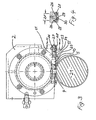
- the deep rolling roller head 1 has an approximately rectangular, flat housing 2.
- the lower end face 3 of the housing. 2 is facing the crankshaft 21, of which Fig. 1 the Section through any main bearing shows whose Bearing journals each side of radii or punctures 22 be limited.
- these radii or punctures 22 engage fixed rollers 4, which in turn with little play between two adjacent roller cages 5 and 6 are rotatably mounted.
- new condition of the Deep rolling tool is the game between the Deep rolling roller 4 and the two roller cages 5 and 6 each about 0.1 mm to 0.5 mm, preferably 0.2 mm.
- the End faces 8 of the two roller cages 5 and 6 have a lateral distance from each other and also a lateral Distance to the center of rotation 7 of the housing. 2
- FIG. 2 shows the two recesses 9 on the front side 8 of a roller cage 5.
- the in the Figure 2 recognizable inclined position of the two recesses. 9 at the same time corresponds to the inclined position of the deep rolling rollers. 4 in the deep rolling head 1.
- roller cages 5 and 6 are supported corresponding projections 11 and 12 from.
- the projections 11 and 12 each jump on the bottom 3 of Housing 2 and give between each other Recess 13 free, wherein the two roller cages 5 and 6 and the deep rolling rollers 4 are received.
- the Roller cages 5 and 6 are connected to the housing 2 or with its projections 11 and 12 not connected. They are in the recess 13 between the both projections 11 and 12 loosely mounted and guided. In this case, the roller cages 5 and 6 are based with their rear end faces 10 each on corresponding Surface 14 of the projections 11 and 12 from.
- each tabs 15 are provided.
- the tabs 15 exist made of flat irons of small length and width, and are in each case via screws 16 with the respective projection 11 or 12 of the housing 2 releasably connected.
- the front, freely projecting end of the two tabs 15 attacks each in a groove 18, which on the bottom 19 of the Roller cage 5 and 6 is provided (Fig. 2).
- two tabs 15 may also be a single tab be provided, which via the two roller cages. 5 and 6 engages and the distance between the end faces. 8 bridged.
- a spacer 20 inserted, the even only a small thickness between 0.1 mm and 0.5 mm, preferably 0.2 mm.
- About the spacer 20 can the game between the deep rolling 4 and the Both roller cages 5 and 6 are compensated.
- the spacer 20 but also serves to the Center of rotation of the deep rolling roller 4 with respect to Center of rotation 7 of the housing 2 by a small amount, which is also between 0.1 mm and 0.5 mm, preferably 0.2 mm, adjust.
- tab 15 may also be a pin provided be, which is the holder and guide of each Roller cage 5 and 6 on the projection 11 and 12 of the housing 2 secures.
- the spacer 23 of Fig. 3 is a prismatic body of opposite to the thickness of the Spacer 20 of FIG. 1 substantially larger axial Length. 3 shows only a single spacer 23, which the adjacent roll cage 5 on his rear end face 10 is supported. Analogous to this also the roller cage 6 a similar spacer be assigned according to the spacer 23.
- the spacer 23 is on two cylindrical pins 24 out in the mutual distance 25 from each other in holes 26th engage within the projection 11 of the housing 2.
- the pins 24 are parts of the spacer 23 and with this firmly and inextricably linked.
- the distance 25 makes room for the engagement of the screw 16 for the Tab 15 in the projection 11th
Landscapes
- Engineering & Computer Science (AREA)
- Mechanical Engineering (AREA)
- Life Sciences & Earth Sciences (AREA)
- Agronomy & Crop Science (AREA)
- Shafts, Cranks, Connecting Bars, And Related Bearings (AREA)
- Rolling Contact Bearings (AREA)
Abstract
Description
- Fig. leinen Festwalzrollenkopf in der Seitenansicht
- Fig. 2 einen Rollenkäfig in der Vorderansicht,
- Fig. 3 einen weiteren Festwalzrollenkopf mit teilweise geschnittener Seitenansicht und
- Fig. 4 einen Längsschnitt durch den Festwalzrollenkopf der Fig. 3 entlang der Linie IV - IV.
- 1
- Festwalzrollenkopf
- 2
- Gehäuse
- 3
- Unterseite
- 4
- Festwalzrolle
- 5
- Rollenkäfig
- 6
- Rollenkäfig
- 7
- Drehmittelpunkt
- 8
- Stirnseite
- 9
- Ausnehmung
- 10
- Stirnseite
- 11
- Vorsprung
- 12
- Vorsprung
- 13
- Ausnehmung
- 14
- Stützfläche
- 15
- Lasche
- 16
- Schraube
- 17
- vorderes Ende
- 18
- Nut
- 19
- Unterseite
- 20
- Distanzstück
- 21
- Kurbelwelle
- 22
- Einstich
- 23
- Distanzstück
- 24
- Zapfen
- 25
- Abstand
- 26
- Bohrung
- 27
- Ende der Bohrung
- 28
- Madenschraube
- 29
- Schraube
- 30
- Unterlegscheibe
Claims (5)
- Festwalzrollenkopf eines Festwalzwerkzeugs zum Festwalzen von Radien oder Einstichen an den Haupt- und Hublagerzapfen von Kurbelwellen mit einem Gehäuse, in welchem eine oder zwei Festwalzrollen in seitlichem Abstand voneinander, entsprechend der axialen Breite des jeweiligen Lagerzapfens, mit geringem Spiel in jeweils zwei Rollenkäfigen lose drehbar geführt sind und die Rollenkäfige auf der der Kurbelwelle zugewandten Stirnseite des Gehäuses mit Haltern befestigt sind, welche die Rollenkäfige jeweils auf ihren den Festwalzrollen abgewandten Stirnseiten abstützen und zugleich seitlich führen,
dadurch gekennzeichnet, dassdas Gehäuse (2) auf seiner der Kurbelwelle (21) zugewandten Stirnseite (3)an deren beiden Enden jeweils einen Vorsprung (11, 12) zum Abstützen von je einem der beiden Rollenkäfige (5, 6) aufweist undein Befestigungs- und Führungsorgan (15) für die Rollenkäfige (5, 6) vorgesehen ist, das in jeden Rollenkäfig (5, 6) eingreift und am Vorsprung (11, 12) des Gehäuses (2) befestigbar ist. - Festwalzrollenkopf nach Anspruch 1, dadurch gekennzeichnet, dass das Befestigungsorgan als Lasche (15) ausgebildet ist, die in eine Längsnut (18) des jeweiligen Rollenkäfigs (5, 6) eingreift, die auf dessen, der Kurbelwelle (21) zugewandten Unterseite (3) vorgesehen ist.
- Festwalzrollenkopf nach einem der Ansprüchen 1 oder 2, dadurch gekennzeichnet, dass zwischen dem Vorsprung (11, 12) des Gehäuses (2) und der sich darauf abstützenden Stirnseite (10) des Rollenkäfigs (5, 6) ein Distanzstück (20, 23) vorgesehen ist.
- Festwalzrollenkopf nach Anspruch 3, dadurch gekennzeichnet, dass das Distanzstück (23) in Richtung auf den angrenzenden Rollenkäfig (5) verstellbar ist.
- Festwalzrollenkopf nach Anspruch 4, dadurch gekennzeichnet, dass die Lage des Distanzstücks (23) feststellbar ist.
Applications Claiming Priority (3)
| Application Number | Priority Date | Filing Date | Title |
|---|---|---|---|
| DE10218703 | 2002-04-26 | ||
| DE10218703 | 2002-04-26 | ||
| PCT/EP2003/001531 WO2003090971A1 (de) | 2002-04-26 | 2003-02-15 | Festwalzrollenkopf eines festwalzwerkzeugs |
Publications (2)
| Publication Number | Publication Date |
|---|---|
| EP1499475A1 EP1499475A1 (de) | 2005-01-26 |
| EP1499475B1 true EP1499475B1 (de) | 2005-12-28 |
Family
ID=29224779
Family Applications (2)
| Application Number | Title | Priority Date | Filing Date |
|---|---|---|---|
| EP03704629A Expired - Fee Related EP1499475B1 (de) | 2002-04-26 | 2003-02-15 | Festwalzrollenkopf eines festwalzwerkzeugs |
| EP03720526A Expired - Fee Related EP1499476B1 (de) | 2002-04-26 | 2003-04-25 | Festwalzrollenkopf eines festwalzwerkzeugs |
Family Applications After (1)
| Application Number | Title | Priority Date | Filing Date |
|---|---|---|---|
| EP03720526A Expired - Fee Related EP1499476B1 (de) | 2002-04-26 | 2003-04-25 | Festwalzrollenkopf eines festwalzwerkzeugs |
Country Status (5)
| Country | Link |
|---|---|
| US (2) | US7168278B2 (de) |
| EP (2) | EP1499475B1 (de) |
| AU (2) | AU2003206907A1 (de) |
| DE (3) | DE50302066D1 (de) |
| WO (2) | WO2003090971A1 (de) |
Cited By (1)
| Publication number | Priority date | Publication date | Assignee | Title |
|---|---|---|---|---|
| DE102005049646A1 (de) * | 2005-10-18 | 2007-04-26 | Hegenscheidt-Mfd Gmbh & Co. Kg | Festwalzrollenkopf eines Festwalzwerkzeugs |
Families Citing this family (8)
| Publication number | Priority date | Publication date | Assignee | Title |
|---|---|---|---|---|
| DE50302066D1 (de) | 2002-04-26 | 2006-02-02 | Hegenscheidt Mfd Gmbh & Co Kg | Festwalzrollenkopf eines festwalzwerkzeugs |
| US7093471B2 (en) * | 2003-04-18 | 2006-08-22 | Lonero Vincent J | Split cage for a deep rolling mechanism |
| DE10357441B3 (de) * | 2003-12-09 | 2005-03-24 | Hegenscheidt-Mfd Gmbh & Co. Kg | Festwalzrollenkopf für Split-Pin-Kurbelwellen |
| GB0600878D0 (en) | 2006-01-17 | 2006-02-22 | Beru F1 Systems Ltd | Multiple wires array |
| DE202007016473U1 (de) * | 2007-11-24 | 2008-03-13 | Hegenscheidt-Mfd Gmbh & Co. Kg | Festwalzrollenkopf eines Festwalzwerkzeugs |
| DE202008007563U1 (de) * | 2008-06-05 | 2008-10-02 | Hegenscheidt-Mfd Gmbh & Co. Kg | Festwalzrollenkopf |
| DE102010008693A1 (de) * | 2010-02-19 | 2011-08-25 | Ferroll GmbH, 29227 | Walzkörperführung mit separat austauschbarem Walzkörper sowie Aufnahmeabschnitt und Walzwerkzeug mit zugehörigem Austauschverfahren |
| US20140041433A1 (en) * | 2012-08-09 | 2014-02-13 | Ingersoll CM Systems | Rolling tool assemblies for crankshaft rolling machines |
Family Cites Families (11)
| Publication number | Priority date | Publication date | Assignee | Title |
|---|---|---|---|---|
| DE1005869B (de) | 1955-07-11 | 1957-04-04 | Wilhelm Hegenscheidt Kommandit | Geraet zum Festwalzen von Hohlkehlen |
| US5575167A (en) | 1994-01-03 | 1996-11-19 | Hegenscheidt Corporation | Deep rolling split-pin fillets of crankshafts |
| US5445003A (en) * | 1994-01-03 | 1995-08-29 | Hegenscheidt Corporation | Engine crank pin rolling equipment, rolling tool and method of rolling adjacent and offset crank pins |
| US5699692A (en) | 1996-10-30 | 1997-12-23 | Lonero Engineering Co., Inc. | Tool mechanisms for deep rolling machines |
| US6253590B1 (en) * | 2000-04-25 | 2001-07-03 | Lonero Engineering Company | Deep rolling tool mechanism with novel pin supported cage design |
| US6257037B1 (en) * | 2000-05-02 | 2001-07-10 | Lonero Engineering Co., Inc. | Deep rolling tool mechanism with novel spring containing cage design |
| DE10040146A1 (de) * | 2000-08-17 | 2002-03-07 | Hegenscheidt Mfd Gmbh & Co Kg | Werkzeug zum Festwalzen der Einstiche an Lager- oder Hubzapfen von Kurbelwellen |
| DE10042425B4 (de) * | 2000-08-30 | 2005-03-24 | Hegenscheidt-Mfd Gmbh & Co. Kg | Rollenkäfig |
| DE10044378C2 (de) * | 2000-09-08 | 2002-09-05 | Hegenscheidt Mfd Gmbh & Co Kg | Rollenkäfig zur Führung von wenigstens einer Festwalzrolle |
| US6360574B1 (en) * | 2000-09-18 | 2002-03-26 | Hegenscheidt-Mfd Corporation | Fillet rolling work roller cage |
| DE50302066D1 (de) | 2002-04-26 | 2006-02-02 | Hegenscheidt Mfd Gmbh & Co Kg | Festwalzrollenkopf eines festwalzwerkzeugs |
-
2003
- 2003-02-15 DE DE50302066T patent/DE50302066D1/de not_active Expired - Fee Related
- 2003-02-15 US US10/526,204 patent/US7168278B2/en not_active Expired - Fee Related
- 2003-02-15 AU AU2003206907A patent/AU2003206907A1/en not_active Abandoned
- 2003-02-15 WO PCT/EP2003/001531 patent/WO2003090971A1/de not_active Application Discontinuation
- 2003-02-15 EP EP03704629A patent/EP1499475B1/de not_active Expired - Fee Related
- 2003-04-25 AU AU2003224125A patent/AU2003224125A1/en not_active Abandoned
- 2003-04-25 US US10/504,107 patent/US7100412B2/en not_active Expired - Fee Related
- 2003-04-25 DE DE10318766A patent/DE10318766B4/de not_active Expired - Fee Related
- 2003-04-25 EP EP03720526A patent/EP1499476B1/de not_active Expired - Fee Related
- 2003-04-25 WO PCT/EP2003/004305 patent/WO2003090972A1/de not_active Application Discontinuation
- 2003-04-25 DE DE50302606T patent/DE50302606D1/de not_active Expired - Lifetime
Cited By (1)
| Publication number | Priority date | Publication date | Assignee | Title |
|---|---|---|---|---|
| DE102005049646A1 (de) * | 2005-10-18 | 2007-04-26 | Hegenscheidt-Mfd Gmbh & Co. Kg | Festwalzrollenkopf eines Festwalzwerkzeugs |
Also Published As
| Publication number | Publication date |
|---|---|
| DE10318766A1 (de) | 2003-11-13 |
| US7168278B2 (en) | 2007-01-30 |
| WO2003090971A1 (de) | 2003-11-06 |
| DE50302606D1 (de) | 2006-05-04 |
| DE10318766B4 (de) | 2009-03-12 |
| US20050066700A1 (en) | 2005-03-31 |
| AU2003206907A1 (en) | 2003-11-10 |
| EP1499476A1 (de) | 2005-01-26 |
| EP1499475A1 (de) | 2005-01-26 |
| WO2003090972A1 (de) | 2003-11-06 |
| DE50302066D1 (de) | 2006-02-02 |
| US20060150700A1 (en) | 2006-07-13 |
| EP1499476B1 (de) | 2006-03-08 |
| US7100412B2 (en) | 2006-09-05 |
| AU2003224125A1 (en) | 2003-11-10 |
Similar Documents
| Publication | Publication Date | Title |
|---|---|---|
| DE640898C (de) | Nockenantrieb | |
| EP1499475B1 (de) | Festwalzrollenkopf eines festwalzwerkzeugs | |
| DE2448814B2 (de) | Vorrichtung zur stanzdruckregulierung einer tiegelstanzpresse sowie zur justierung der tiegel zueinander | |
| DE3237057A1 (de) | Stativbohrgeraet | |
| DE10044378C2 (de) | Rollenkäfig zur Führung von wenigstens einer Festwalzrolle | |
| EP1948373B1 (de) | Festwalzrollenkopf eines festwalzwerkzeugs | |
| CH632426A5 (de) | Walzgeruest. | |
| DE600475C (de) | Tuerschloss fuer verschiedene Dornmasse | |
| DE10253345B4 (de) | Vorrichtung zur Erleichterung der Hammermühlenwartung | |
| DE974538C (de) | Entlastungsvorrichtung fuer die Fuehrung von auf waagerechten Gleitbahnen beweglichen Maschinenteilen, z. B. fuer den Spindelstock eines Horzontal-Bohr- und Fraeswerks | |
| DE632271C (de) | Oberer Laufrollenbeschlag fuer haengende Schiebetueren | |
| WO2004004972A1 (de) | Festwalzrollenkopf | |
| WO2013013658A1 (de) | Glattwalzkopf | |
| DE2633883A1 (de) | Walzentyp-gewindeschneideisen | |
| AT143802B (de) | Apparat zum Schleifen und Polieren von Chatons u. dgl. | |
| DE1477040A1 (de) | Werkzeughalter fuer Walzwerkzeuge | |
| DE893785C (de) | Kalander oder Walzwerk, insbesondere Praegekalander | |
| DE664259C (de) | Vorrichtung zum Herstellen von Drahtziegelgewebe mittels Walzen | |
| DE446448C (de) | Rollenfuehrungsbuechse zum Gewindeschneiden u. dgl. mit Vorrichtung zum Verstellen der Fuehrungsrollen durch die Ratsche | |
| DE590409C (de) | Universalwalzwerk | |
| DE970370C (de) | Oberwalzen fuer Spinnereimaschinen | |
| DE520451C (de) | Randbiegemaschine fuer Bleche | |
| DE826524C (de) | Saewellenlger fuer Saemaschinen | |
| DE389385C (de) | Mit federnder Ausgleichvorrichtung versehene Stellvorrichtung fuer Schiebefenster | |
| DE864537C (de) | Grubenstempel |
Legal Events
| Date | Code | Title | Description |
|---|---|---|---|
| PUAI | Public reference made under article 153(3) epc to a published international application that has entered the european phase |
Free format text: ORIGINAL CODE: 0009012 |
|
| 17P | Request for examination filed |
Effective date: 20041016 |
|
| AK | Designated contracting states |
Kind code of ref document: A1 Designated state(s): AT BE BG CH CY CZ DE DK EE ES FI FR GB GR HU IE IT LI LU MC NL PT SE SI SK TR |
|
| AX | Request for extension of the european patent |
Extension state: AL LT LV MK RO |
|
| GRAP | Despatch of communication of intention to grant a patent |
Free format text: ORIGINAL CODE: EPIDOSNIGR1 |
|
| RAP1 | Party data changed (applicant data changed or rights of an application transferred) |
Owner name: HEGENSCHEIDT-MFD GMBH & CO. KG |
|
| RBV | Designated contracting states (corrected) |
Designated state(s): DE FR |
|
| GRAS | Grant fee paid |
Free format text: ORIGINAL CODE: EPIDOSNIGR3 |
|
| GRAA | (expected) grant |
Free format text: ORIGINAL CODE: 0009210 |
|
| AK | Designated contracting states |
Kind code of ref document: B1 Designated state(s): DE FR |
|
| REF | Corresponds to: |
Ref document number: 50302066 Country of ref document: DE Date of ref document: 20060202 Kind code of ref document: P |
|
| ET | Fr: translation filed | ||
| PLBE | No opposition filed within time limit |
Free format text: ORIGINAL CODE: 0009261 |
|
| STAA | Information on the status of an ep patent application or granted ep patent |
Free format text: STATUS: NO OPPOSITION FILED WITHIN TIME LIMIT |
|
| 26N | No opposition filed |
Effective date: 20060929 |
|
| PGFP | Annual fee paid to national office [announced via postgrant information from national office to epo] |
Ref country code: DE Payment date: 20081204 Year of fee payment: 7 |
|
| PG25 | Lapsed in a contracting state [announced via postgrant information from national office to epo] |
Ref country code: DE Free format text: LAPSE BECAUSE OF NON-PAYMENT OF DUE FEES Effective date: 20100901 |
|
| PGFP | Annual fee paid to national office [announced via postgrant information from national office to epo] |
Ref country code: FR Payment date: 20120227 Year of fee payment: 10 |
|
| REG | Reference to a national code |
Ref country code: FR Ref legal event code: ST Effective date: 20131031 |
|
| PG25 | Lapsed in a contracting state [announced via postgrant information from national office to epo] |
Ref country code: FR Free format text: LAPSE BECAUSE OF NON-PAYMENT OF DUE FEES Effective date: 20130228 |