EP1496555B1 - Composite positive electrode material and method for making same - Google Patents
Composite positive electrode material and method for making same Download PDFInfo
- Publication number
- EP1496555B1 EP1496555B1 EP04024169.7A EP04024169A EP1496555B1 EP 1496555 B1 EP1496555 B1 EP 1496555B1 EP 04024169 A EP04024169 A EP 04024169A EP 1496555 B1 EP1496555 B1 EP 1496555B1
- Authority
- EP
- European Patent Office
- Prior art keywords
- positive electrode
- nickel
- particles
- nickel hydroxide
- electrode material
- Prior art date
- Legal status (The legal status is an assumption and is not a legal conclusion. Google has not performed a legal analysis and makes no representation as to the accuracy of the status listed.)
- Expired - Lifetime
Links
- 239000007774 positive electrode material Substances 0.000 title claims description 77
- 239000002131 composite material Substances 0.000 title claims description 37
- 238000000034 method Methods 0.000 title claims description 19
- 239000002245 particle Substances 0.000 claims description 116
- 239000000463 material Substances 0.000 claims description 96
- 229910021645 metal ion Inorganic materials 0.000 claims description 35
- 230000001965 increasing effect Effects 0.000 claims description 23
- 239000003518 caustics Substances 0.000 claims description 19
- 238000001556 precipitation Methods 0.000 claims description 17
- 229910052751 metal Inorganic materials 0.000 claims description 16
- 239000002184 metal Substances 0.000 claims description 16
- 238000002156 mixing Methods 0.000 claims description 15
- 238000004519 manufacturing process Methods 0.000 claims description 11
- VHUUQVKOLVNVRT-UHFFFAOYSA-N Ammonium hydroxide Chemical compound [NH4+].[OH-] VHUUQVKOLVNVRT-UHFFFAOYSA-N 0.000 claims description 10
- 239000000908 ammonium hydroxide Substances 0.000 claims description 10
- 239000000725 suspension Substances 0.000 claims description 10
- 150000001412 amines Chemical class 0.000 claims description 3
- PXHVJJICTQNCMI-UHFFFAOYSA-N nickel Substances [Ni] PXHVJJICTQNCMI-UHFFFAOYSA-N 0.000 description 170
- BFDHFSHZJLFAMC-UHFFFAOYSA-L nickel(ii) hydroxide Chemical compound [OH-].[OH-].[Ni+2] BFDHFSHZJLFAMC-UHFFFAOYSA-L 0.000 description 128
- 229910052759 nickel Inorganic materials 0.000 description 87
- 239000000243 solution Substances 0.000 description 61
- 239000011149 active material Substances 0.000 description 29
- 239000004020 conductor Substances 0.000 description 27
- 239000003607 modifier Substances 0.000 description 20
- HEMHJVSKTPXQMS-UHFFFAOYSA-M Sodium hydroxide Chemical compound [OH-].[Na+] HEMHJVSKTPXQMS-UHFFFAOYSA-M 0.000 description 18
- 239000011701 zinc Substances 0.000 description 18
- 238000010899 nucleation Methods 0.000 description 17
- 230000006911 nucleation Effects 0.000 description 17
- 238000012546 transfer Methods 0.000 description 15
- 229910052725 zinc Inorganic materials 0.000 description 15
- 229910017052 cobalt Inorganic materials 0.000 description 14
- 239000010941 cobalt Substances 0.000 description 14
- GUTLYIVDDKVIGB-UHFFFAOYSA-N cobalt atom Chemical compound [Co] GUTLYIVDDKVIGB-UHFFFAOYSA-N 0.000 description 14
- 239000000835 fiber Substances 0.000 description 13
- 229910018095 Ni-MH Inorganic materials 0.000 description 12
- 229910018477 Ni—MH Inorganic materials 0.000 description 12
- OKTJSMMVPCPJKN-UHFFFAOYSA-N Carbon Chemical compound [C] OKTJSMMVPCPJKN-UHFFFAOYSA-N 0.000 description 10
- QVGXLLKOCUKJST-UHFFFAOYSA-N atomic oxygen Chemical compound [O] QVGXLLKOCUKJST-UHFFFAOYSA-N 0.000 description 10
- 229910052788 barium Inorganic materials 0.000 description 10
- 229910052802 copper Inorganic materials 0.000 description 10
- 239000010949 copper Substances 0.000 description 10
- 239000006260 foam Substances 0.000 description 10
- 229910052760 oxygen Inorganic materials 0.000 description 10
- 239000001301 oxygen Substances 0.000 description 10
- 150000001875 compounds Chemical class 0.000 description 9
- 230000006872 improvement Effects 0.000 description 9
- 229910052748 manganese Inorganic materials 0.000 description 9
- 239000011572 manganese Substances 0.000 description 9
- 229910052712 strontium Inorganic materials 0.000 description 9
- 239000000654 additive Substances 0.000 description 8
- 229910052782 aluminium Inorganic materials 0.000 description 8
- 229910052804 chromium Inorganic materials 0.000 description 8
- 230000000694 effects Effects 0.000 description 8
- 229910052742 iron Inorganic materials 0.000 description 8
- XEEYBQQBJWHFJM-UHFFFAOYSA-N iron Substances [Fe] XEEYBQQBJWHFJM-UHFFFAOYSA-N 0.000 description 8
- 230000002829 reductive effect Effects 0.000 description 8
- 239000000126 substance Substances 0.000 description 8
- 239000000758 substrate Substances 0.000 description 8
- 230000008961 swelling Effects 0.000 description 8
- 229910005813 NiMH Inorganic materials 0.000 description 7
- 230000015572 biosynthetic process Effects 0.000 description 7
- IVMYJDGYRUAWML-UHFFFAOYSA-N cobalt(ii) oxide Chemical compound [Co]=O IVMYJDGYRUAWML-UHFFFAOYSA-N 0.000 description 7
- 229910052738 indium Inorganic materials 0.000 description 7
- 229910052749 magnesium Inorganic materials 0.000 description 7
- 239000011777 magnesium Substances 0.000 description 7
- 229910052727 yttrium Inorganic materials 0.000 description 7
- 229910052793 cadmium Inorganic materials 0.000 description 6
- 229910052791 calcium Inorganic materials 0.000 description 6
- 239000011575 calcium Substances 0.000 description 6
- ZCCIPPOKBCJFDN-UHFFFAOYSA-N calcium nitrate Chemical compound [Ca+2].[O-][N+]([O-])=O.[O-][N+]([O-])=O ZCCIPPOKBCJFDN-UHFFFAOYSA-N 0.000 description 6
- 229910052799 carbon Inorganic materials 0.000 description 6
- 239000013078 crystal Substances 0.000 description 6
- 239000007772 electrode material Substances 0.000 description 6
- 239000003792 electrolyte Substances 0.000 description 6
- 229910052744 lithium Inorganic materials 0.000 description 6
- -1 nickel metal hydride Chemical class 0.000 description 6
- 229910052700 potassium Inorganic materials 0.000 description 6
- 229910052708 sodium Inorganic materials 0.000 description 6
- 239000011734 sodium Substances 0.000 description 6
- 239000006104 solid solution Substances 0.000 description 6
- 229910052718 tin Inorganic materials 0.000 description 6
- 229910002640 NiOOH Inorganic materials 0.000 description 5
- 238000006243 chemical reaction Methods 0.000 description 5
- NPURPEXKKDAKIH-UHFFFAOYSA-N iodoimino(oxo)methane Chemical compound IN=C=O NPURPEXKKDAKIH-UHFFFAOYSA-N 0.000 description 5
- 238000002955 isolation Methods 0.000 description 5
- 230000003647 oxidation Effects 0.000 description 5
- 238000007254 oxidation reaction Methods 0.000 description 5
- 230000037361 pathway Effects 0.000 description 5
- 230000009467 reduction Effects 0.000 description 5
- 229910005580 NiCd Inorganic materials 0.000 description 4
- KWYUFKZDYYNOTN-UHFFFAOYSA-M Potassium hydroxide Chemical compound [OH-].[K+] KWYUFKZDYYNOTN-UHFFFAOYSA-M 0.000 description 4
- 229910052787 antimony Inorganic materials 0.000 description 4
- 239000011651 chromium Substances 0.000 description 4
- 229910052739 hydrogen Inorganic materials 0.000 description 4
- 239000001257 hydrogen Substances 0.000 description 4
- 238000002847 impedance measurement Methods 0.000 description 4
- 238000010348 incorporation Methods 0.000 description 4
- 229910052987 metal hydride Inorganic materials 0.000 description 4
- 238000012986 modification Methods 0.000 description 4
- 230000004048 modification Effects 0.000 description 4
- 239000000843 powder Substances 0.000 description 4
- XLYOFNOQVPJJNP-UHFFFAOYSA-N water Substances O XLYOFNOQVPJJNP-UHFFFAOYSA-N 0.000 description 4
- 229910006279 γ-NiOOH Inorganic materials 0.000 description 4
- 229910021503 Cobalt(II) hydroxide Inorganic materials 0.000 description 3
- RYGMFSIKBFXOCR-UHFFFAOYSA-N Copper Chemical compound [Cu] RYGMFSIKBFXOCR-UHFFFAOYSA-N 0.000 description 3
- UFHFLCQGNIYNRP-UHFFFAOYSA-N Hydrogen Chemical compound [H][H] UFHFLCQGNIYNRP-UHFFFAOYSA-N 0.000 description 3
- 229910017759 LaH3 Inorganic materials 0.000 description 3
- 229910052779 Neodymium Inorganic materials 0.000 description 3
- HCHKCACWOHOZIP-UHFFFAOYSA-N Zinc Chemical compound [Zn] HCHKCACWOHOZIP-UHFFFAOYSA-N 0.000 description 3
- OSOVKCSKTAIGGF-UHFFFAOYSA-N [Ni].OOO Chemical compound [Ni].OOO OSOVKCSKTAIGGF-UHFFFAOYSA-N 0.000 description 3
- 239000011230 binding agent Substances 0.000 description 3
- 229910052797 bismuth Inorganic materials 0.000 description 3
- 229910000428 cobalt oxide Inorganic materials 0.000 description 3
- ASKVAEGIVYSGNY-UHFFFAOYSA-L cobalt(ii) hydroxide Chemical compound [OH-].[OH-].[Co+2] ASKVAEGIVYSGNY-UHFFFAOYSA-L 0.000 description 3
- 230000008021 deposition Effects 0.000 description 3
- 238000003411 electrode reaction Methods 0.000 description 3
- 229910002804 graphite Inorganic materials 0.000 description 3
- 239000010439 graphite Substances 0.000 description 3
- 229910052746 lanthanum Inorganic materials 0.000 description 3
- 229910052745 lead Inorganic materials 0.000 description 3
- 239000011159 matrix material Substances 0.000 description 3
- 239000000203 mixture Substances 0.000 description 3
- 229910000483 nickel oxide hydroxide Inorganic materials 0.000 description 3
- LGQLOGILCSXPEA-UHFFFAOYSA-L nickel sulfate Chemical compound [Ni+2].[O-]S([O-])(=O)=O LGQLOGILCSXPEA-UHFFFAOYSA-L 0.000 description 3
- 229910000363 nickel(II) sulfate Inorganic materials 0.000 description 3
- 230000008569 process Effects 0.000 description 3
- 230000002441 reversible effect Effects 0.000 description 3
- 229910000048 titanium hydride Inorganic materials 0.000 description 3
- OGIDPMRJRNCKJF-UHFFFAOYSA-N titanium oxide Inorganic materials [Ti]=O OGIDPMRJRNCKJF-UHFFFAOYSA-N 0.000 description 3
- WMFOQBRAJBCJND-UHFFFAOYSA-M Lithium hydroxide Chemical compound [Li+].[OH-] WMFOQBRAJBCJND-UHFFFAOYSA-M 0.000 description 2
- CSNNHWWHGAXBCP-UHFFFAOYSA-L Magnesium sulfate Chemical compound [Mg+2].[O-][S+2]([O-])([O-])[O-] CSNNHWWHGAXBCP-UHFFFAOYSA-L 0.000 description 2
- NBFQLHGCEMEQFN-UHFFFAOYSA-N N.[Ni] Chemical compound N.[Ni] NBFQLHGCEMEQFN-UHFFFAOYSA-N 0.000 description 2
- 229910000990 Ni alloy Inorganic materials 0.000 description 2
- VEQPNABPJHWNSG-UHFFFAOYSA-N Nickel(2+) Chemical compound [Ni+2] VEQPNABPJHWNSG-UHFFFAOYSA-N 0.000 description 2
- QAOWNCQODCNURD-UHFFFAOYSA-L Sulfate Chemical compound [O-]S([O-])(=O)=O QAOWNCQODCNURD-UHFFFAOYSA-L 0.000 description 2
- XLOMVQKBTHCTTD-UHFFFAOYSA-N Zinc monoxide Chemical compound [Zn]=O XLOMVQKBTHCTTD-UHFFFAOYSA-N 0.000 description 2
- 230000002776 aggregation Effects 0.000 description 2
- 238000004220 aggregation Methods 0.000 description 2
- 229910045601 alloy Inorganic materials 0.000 description 2
- 239000000956 alloy Substances 0.000 description 2
- BDOSMKKIYDKNTQ-UHFFFAOYSA-N cadmium atom Chemical compound [Cd] BDOSMKKIYDKNTQ-UHFFFAOYSA-N 0.000 description 2
- HUCVOHYBFXVBRW-UHFFFAOYSA-M caesium hydroxide Chemical compound [OH-].[Cs+] HUCVOHYBFXVBRW-UHFFFAOYSA-M 0.000 description 2
- AXCZMVOFGPJBDE-UHFFFAOYSA-L calcium dihydroxide Chemical compound [OH-].[OH-].[Ca+2] AXCZMVOFGPJBDE-UHFFFAOYSA-L 0.000 description 2
- 239000000920 calcium hydroxide Substances 0.000 description 2
- 229910001861 calcium hydroxide Inorganic materials 0.000 description 2
- 150000001869 cobalt compounds Chemical class 0.000 description 2
- 239000002482 conductive additive Substances 0.000 description 2
- 230000001351 cycling effect Effects 0.000 description 2
- 230000003247 decreasing effect Effects 0.000 description 2
- 239000008367 deionised water Substances 0.000 description 2
- 229910021641 deionized water Inorganic materials 0.000 description 2
- 239000011888 foil Substances 0.000 description 2
- 150000002500 ions Chemical class 0.000 description 2
- 230000000670 limiting effect Effects 0.000 description 2
- IPJKJLXEVHOKSE-UHFFFAOYSA-L manganese dihydroxide Chemical compound [OH-].[OH-].[Mn+2] IPJKJLXEVHOKSE-UHFFFAOYSA-L 0.000 description 2
- 230000007246 mechanism Effects 0.000 description 2
- 150000004681 metal hydrides Chemical class 0.000 description 2
- 229910044991 metal oxide Inorganic materials 0.000 description 2
- 150000002815 nickel Chemical group 0.000 description 2
- 229910001453 nickel ion Inorganic materials 0.000 description 2
- 229910052709 silver Inorganic materials 0.000 description 2
- 238000003860 storage Methods 0.000 description 2
- XMWRBQBLMFGWIX-UHFFFAOYSA-N C60 fullerene Chemical class C12=C3C(C4=C56)=C7C8=C5C5=C9C%10=C6C6=C4C1=C1C4=C6C6=C%10C%10=C9C9=C%11C5=C8C5=C8C7=C3C3=C7C2=C1C1=C2C4=C6C4=C%10C6=C9C9=C%11C5=C5C8=C3C3=C7C1=C1C2=C4C6=C2C9=C5C3=C12 XMWRBQBLMFGWIX-UHFFFAOYSA-N 0.000 description 1
- OYPRJOBELJOOCE-UHFFFAOYSA-N Calcium Chemical compound [Ca] OYPRJOBELJOOCE-UHFFFAOYSA-N 0.000 description 1
- 239000004343 Calcium peroxide Substances 0.000 description 1
- QPLDLSVMHZLSFG-UHFFFAOYSA-N Copper oxide Chemical compound [Cu]=O QPLDLSVMHZLSFG-UHFFFAOYSA-N 0.000 description 1
- 239000005751 Copper oxide Substances 0.000 description 1
- 229910000881 Cu alloy Inorganic materials 0.000 description 1
- 240000007175 Datura inoxia Species 0.000 description 1
- FYYHWMGAXLPEAU-UHFFFAOYSA-N Magnesium Chemical compound [Mg] FYYHWMGAXLPEAU-UHFFFAOYSA-N 0.000 description 1
- 229910003266 NiCo Inorganic materials 0.000 description 1
- 229910006015 NiCoCd Inorganic materials 0.000 description 1
- 229910006027 NiCoMg Inorganic materials 0.000 description 1
- 229910006083 NiCoZn Inorganic materials 0.000 description 1
- 238000010521 absorption reaction Methods 0.000 description 1
- 230000002378 acidificating effect Effects 0.000 description 1
- 230000004913 activation Effects 0.000 description 1
- 230000000996 additive effect Effects 0.000 description 1
- 150000008044 alkali metal hydroxides Chemical class 0.000 description 1
- 230000004075 alteration Effects 0.000 description 1
- WATWJIUSRGPENY-UHFFFAOYSA-N antimony atom Chemical compound [Sb] WATWJIUSRGPENY-UHFFFAOYSA-N 0.000 description 1
- 125000004429 atom Chemical group 0.000 description 1
- DSAJWYNOEDNPEQ-UHFFFAOYSA-N barium atom Chemical compound [Ba] DSAJWYNOEDNPEQ-UHFFFAOYSA-N 0.000 description 1
- 229910052790 beryllium Inorganic materials 0.000 description 1
- ATBAMAFKBVZNFJ-UHFFFAOYSA-N beryllium atom Chemical compound [Be] ATBAMAFKBVZNFJ-UHFFFAOYSA-N 0.000 description 1
- OJIJEKBXJYRIBZ-UHFFFAOYSA-N cadmium nickel Chemical compound [Ni].[Cd] OJIJEKBXJYRIBZ-UHFFFAOYSA-N 0.000 description 1
- 229910052792 caesium Inorganic materials 0.000 description 1
- WUKWITHWXAAZEY-UHFFFAOYSA-L calcium difluoride Chemical compound [F-].[F-].[Ca+2] WUKWITHWXAAZEY-UHFFFAOYSA-L 0.000 description 1
- 229910001634 calcium fluoride Inorganic materials 0.000 description 1
- BRPQOXSCLDDYGP-UHFFFAOYSA-N calcium oxide Chemical compound [O-2].[Ca+2] BRPQOXSCLDDYGP-UHFFFAOYSA-N 0.000 description 1
- 239000000292 calcium oxide Substances 0.000 description 1
- ODINCKMPIJJUCX-UHFFFAOYSA-N calcium oxide Inorganic materials [Ca]=O ODINCKMPIJJUCX-UHFFFAOYSA-N 0.000 description 1
- LHJQIRIGXXHNLA-UHFFFAOYSA-N calcium peroxide Chemical compound [Ca+2].[O-][O-] LHJQIRIGXXHNLA-UHFFFAOYSA-N 0.000 description 1
- 235000019402 calcium peroxide Nutrition 0.000 description 1
- 239000000378 calcium silicate Substances 0.000 description 1
- 229910052918 calcium silicate Inorganic materials 0.000 description 1
- OYACROKNLOSFPA-UHFFFAOYSA-N calcium;dioxido(oxo)silane Chemical compound [Ca+2].[O-][Si]([O-])=O OYACROKNLOSFPA-UHFFFAOYSA-N 0.000 description 1
- 239000002041 carbon nanotube Substances 0.000 description 1
- 229910021393 carbon nanotube Inorganic materials 0.000 description 1
- 230000001413 cellular effect Effects 0.000 description 1
- 230000008859 change Effects 0.000 description 1
- 239000003795 chemical substances by application Substances 0.000 description 1
- KTVIXTQDYHMGHF-UHFFFAOYSA-L cobalt(2+) sulfate Chemical compound [Co+2].[O-]S([O-])(=O)=O KTVIXTQDYHMGHF-UHFFFAOYSA-L 0.000 description 1
- 239000000470 constituent Substances 0.000 description 1
- 229910000431 copper oxide Inorganic materials 0.000 description 1
- 230000002939 deleterious effect Effects 0.000 description 1
- 238000013461 design Methods 0.000 description 1
- 230000001066 destructive effect Effects 0.000 description 1
- 238000002848 electrochemical method Methods 0.000 description 1
- 238000004146 energy storage Methods 0.000 description 1
- 238000005516 engineering process Methods 0.000 description 1
- 230000002708 enhancing effect Effects 0.000 description 1
- 230000007613 environmental effect Effects 0.000 description 1
- 238000003912 environmental pollution Methods 0.000 description 1
- 238000009472 formulation Methods 0.000 description 1
- 229910003472 fullerene Inorganic materials 0.000 description 1
- 238000007429 general method Methods 0.000 description 1
- XLYOFNOQVPJJNP-UHFFFAOYSA-M hydroxide Chemical compound [OH-] XLYOFNOQVPJJNP-UHFFFAOYSA-M 0.000 description 1
- 150000004679 hydroxides Chemical class 0.000 description 1
- APFVFJFRJDLVQX-UHFFFAOYSA-N indium atom Chemical compound [In] APFVFJFRJDLVQX-UHFFFAOYSA-N 0.000 description 1
- AMGQUBHHOARCQH-UHFFFAOYSA-N indium;oxotin Chemical compound [In].[Sn]=O AMGQUBHHOARCQH-UHFFFAOYSA-N 0.000 description 1
- 239000003112 inhibitor Substances 0.000 description 1
- 230000002401 inhibitory effect Effects 0.000 description 1
- UGKDIUIOSMUOAW-UHFFFAOYSA-N iron nickel Chemical compound [Fe].[Ni] UGKDIUIOSMUOAW-UHFFFAOYSA-N 0.000 description 1
- 229910052943 magnesium sulfate Inorganic materials 0.000 description 1
- 238000012423 maintenance Methods 0.000 description 1
- 229910001437 manganese ion Inorganic materials 0.000 description 1
- 150000001247 metal acetylides Chemical class 0.000 description 1
- 229910001960 metal nitrate Inorganic materials 0.000 description 1
- 239000013528 metallic particle Substances 0.000 description 1
- 150000002739 metals Chemical class 0.000 description 1
- QELJHCBNGDEXLD-UHFFFAOYSA-N nickel zinc Chemical compound [Ni].[Zn] QELJHCBNGDEXLD-UHFFFAOYSA-N 0.000 description 1
- AIBQNUOBCRIENU-UHFFFAOYSA-N nickel;dihydrate Chemical compound O.O.[Ni] AIBQNUOBCRIENU-UHFFFAOYSA-N 0.000 description 1
- 150000004767 nitrides Chemical class 0.000 description 1
- 230000000737 periodic effect Effects 0.000 description 1
- 239000004033 plastic Substances 0.000 description 1
- 231100000614 poison Toxicity 0.000 description 1
- 239000002574 poison Substances 0.000 description 1
- 239000002244 precipitate Substances 0.000 description 1
- 230000001737 promoting effect Effects 0.000 description 1
- 229910052761 rare earth metal Inorganic materials 0.000 description 1
- 238000006479 redox reaction Methods 0.000 description 1
- 230000027756 respiratory electron transport chain Effects 0.000 description 1
- 150000003839 salts Chemical class 0.000 description 1
- 229910021332 silicide Inorganic materials 0.000 description 1
- 239000002002 slurry Substances 0.000 description 1
- 238000012360 testing method Methods 0.000 description 1
- 231100000701 toxic element Toxicity 0.000 description 1
- 230000007704 transition Effects 0.000 description 1
- 229910052720 vanadium Inorganic materials 0.000 description 1
- 239000000080 wetting agent Substances 0.000 description 1
- VWQVUPCCIRVNHF-UHFFFAOYSA-N yttrium atom Chemical compound [Y] VWQVUPCCIRVNHF-UHFFFAOYSA-N 0.000 description 1
- 239000011787 zinc oxide Substances 0.000 description 1
- NWONKYPBYAMBJT-UHFFFAOYSA-L zinc sulfate Chemical compound [Zn+2].[O-]S([O-])(=O)=O NWONKYPBYAMBJT-UHFFFAOYSA-L 0.000 description 1
- 229910000368 zinc sulfate Inorganic materials 0.000 description 1
- 239000011686 zinc sulphate Substances 0.000 description 1
Images

Classifications
-
- H—ELECTRICITY
- H01—ELECTRIC ELEMENTS
- H01M—PROCESSES OR MEANS, e.g. BATTERIES, FOR THE DIRECT CONVERSION OF CHEMICAL ENERGY INTO ELECTRICAL ENERGY
- H01M4/00—Electrodes
- H01M4/02—Electrodes composed of, or comprising, active material
- H01M4/13—Electrodes for accumulators with non-aqueous electrolyte, e.g. for lithium-accumulators; Processes of manufacture thereof
- H01M4/139—Processes of manufacture
- H01M4/1395—Processes of manufacture of electrodes based on metals, Si or alloys
-
- H—ELECTRICITY
- H01—ELECTRIC ELEMENTS
- H01M—PROCESSES OR MEANS, e.g. BATTERIES, FOR THE DIRECT CONVERSION OF CHEMICAL ENERGY INTO ELECTRICAL ENERGY
- H01M4/00—Electrodes
- H01M4/02—Electrodes composed of, or comprising, active material
- H01M4/62—Selection of inactive substances as ingredients for active masses, e.g. binders, fillers
- H01M4/624—Electric conductive fillers
- H01M4/626—Metals
-
- H—ELECTRICITY
- H01—ELECTRIC ELEMENTS
- H01M—PROCESSES OR MEANS, e.g. BATTERIES, FOR THE DIRECT CONVERSION OF CHEMICAL ENERGY INTO ELECTRICAL ENERGY
- H01M4/00—Electrodes
- H01M4/02—Electrodes composed of, or comprising, active material
- H01M4/04—Processes of manufacture in general
-
- H—ELECTRICITY
- H01—ELECTRIC ELEMENTS
- H01M—PROCESSES OR MEANS, e.g. BATTERIES, FOR THE DIRECT CONVERSION OF CHEMICAL ENERGY INTO ELECTRICAL ENERGY
- H01M4/00—Electrodes
- H01M4/02—Electrodes composed of, or comprising, active material
- H01M4/24—Electrodes for alkaline accumulators
- H01M4/32—Nickel oxide or hydroxide electrodes
-
- H—ELECTRICITY
- H01—ELECTRIC ELEMENTS
- H01M—PROCESSES OR MEANS, e.g. BATTERIES, FOR THE DIRECT CONVERSION OF CHEMICAL ENERGY INTO ELECTRICAL ENERGY
- H01M4/00—Electrodes
- H01M4/02—Electrodes composed of, or comprising, active material
- H01M4/36—Selection of substances as active materials, active masses, active liquids
- H01M4/48—Selection of substances as active materials, active masses, active liquids of inorganic oxides or hydroxides
- H01M4/52—Selection of substances as active materials, active masses, active liquids of inorganic oxides or hydroxides of nickel, cobalt or iron
-
- H—ELECTRICITY
- H01—ELECTRIC ELEMENTS
- H01M—PROCESSES OR MEANS, e.g. BATTERIES, FOR THE DIRECT CONVERSION OF CHEMICAL ENERGY INTO ELECTRICAL ENERGY
- H01M4/00—Electrodes
- H01M4/02—Electrodes composed of, or comprising, active material
- H01M4/62—Selection of inactive substances as ingredients for active masses, e.g. binders, fillers
- H01M4/624—Electric conductive fillers
-
- H—ELECTRICITY
- H01—ELECTRIC ELEMENTS
- H01M—PROCESSES OR MEANS, e.g. BATTERIES, FOR THE DIRECT CONVERSION OF CHEMICAL ENERGY INTO ELECTRICAL ENERGY
- H01M4/00—Electrodes
- H01M4/02—Electrodes composed of, or comprising, active material
-
- H—ELECTRICITY
- H01—ELECTRIC ELEMENTS
- H01M—PROCESSES OR MEANS, e.g. BATTERIES, FOR THE DIRECT CONVERSION OF CHEMICAL ENERGY INTO ELECTRICAL ENERGY
- H01M4/00—Electrodes
- H01M4/02—Electrodes composed of, or comprising, active material
- H01M4/62—Selection of inactive substances as ingredients for active masses, e.g. binders, fillers
- H01M4/624—Electric conductive fillers
- H01M4/625—Carbon or graphite
-
- Y—GENERAL TAGGING OF NEW TECHNOLOGICAL DEVELOPMENTS; GENERAL TAGGING OF CROSS-SECTIONAL TECHNOLOGIES SPANNING OVER SEVERAL SECTIONS OF THE IPC; TECHNICAL SUBJECTS COVERED BY FORMER USPC CROSS-REFERENCE ART COLLECTIONS [XRACs] AND DIGESTS
- Y02—TECHNOLOGIES OR APPLICATIONS FOR MITIGATION OR ADAPTATION AGAINST CLIMATE CHANGE
- Y02E—REDUCTION OF GREENHOUSE GAS [GHG] EMISSIONS, RELATED TO ENERGY GENERATION, TRANSMISSION OR DISTRIBUTION
- Y02E60/00—Enabling technologies; Technologies with a potential or indirect contribution to GHG emissions mitigation
- Y02E60/10—Energy storage using batteries
-
- Y—GENERAL TAGGING OF NEW TECHNOLOGICAL DEVELOPMENTS; GENERAL TAGGING OF CROSS-SECTIONAL TECHNOLOGIES SPANNING OVER SEVERAL SECTIONS OF THE IPC; TECHNICAL SUBJECTS COVERED BY FORMER USPC CROSS-REFERENCE ART COLLECTIONS [XRACs] AND DIGESTS
- Y02—TECHNOLOGIES OR APPLICATIONS FOR MITIGATION OR ADAPTATION AGAINST CLIMATE CHANGE
- Y02P—CLIMATE CHANGE MITIGATION TECHNOLOGIES IN THE PRODUCTION OR PROCESSING OF GOODS
- Y02P70/00—Climate change mitigation technologies in the production process for final industrial or consumer products
- Y02P70/50—Manufacturing or production processes characterised by the final manufactured product
Definitions
- the instant invention relates generally to positive electrode materials for rechargeable batteries such as nickel hydroxide materials. More specifically, the instant invention relates to composite nickel hydroxide particulate having increased conductivity over the prior art material.
- Rechargeable alkaline cells In rechargeable alkaline cells, weight and portability are important considerations. It is also advantageous for rechargeable alkaline cells to have long operating lives without the necessity of periodic maintenance.
- Rechargeable alkaline cells are used in numerous consumer devices such as calculators, portable radios, and cellular phones. They are often configured into a sealed power pack that is designed as an integral part of a specific device. Rechargeable alkaline cells can also be configured as larger cells that can be used, for example, in industrial, aerospace, and electric vehicle applications.
- NiCd nickel cadmium
- Ni-MH nickel metal hydride
- nickel hydrogen nickel zinc
- nickel iron cells nickel iron cells
- NiCd rechargeable alkaline cells are the most widely used although it appears that they will be replaced by Ni-MH cells.
- Ni-MH cells made of synthetically engineered materials have superior performance parameters and contain no toxic elements.
- Ni-MH cells utilize a negative electrode that is capable of the reversible electrochemical storage of hydrogen.
- Ni-MH cells usually employ a positive electrode of nickel hydroxide material. The negative and positive electrodes are spaced apart in the alkaline electrolyte.
- the Ni-MH material of the negative electrode is charged by the electrochemical absorption of hydrogen and the electrochemical discharge- of a hydroxyl ion, as shown in equation (1): M + H 2 ⁇ O + e - ⁇ - > discharge charge M - H + OH -
- the negative electrode reactions are reversible.
- the stored hydrogen is released to form a water molecule and release an electron.
- Ni OH 2 + OH - ⁇ - > discharge charge NiOOH + H 2 ⁇ O + e - Ni-MH materials are discussed in detail in U.S. Patent No. 5,277,999 to Ovshinsky, et al.
- the discharge capacity of a nickel based positive electrode is limited by the amount of active material, and the charging efficiencies.
- the charge capacities of a Cd negative electrode and a MH negative electrode are both provided in excess, to maintain the optimum capacity and provide overcharge protection.
- a goal in making the nickel positive electrode is to obtain as high an energy density as possible.
- the volume of a nickel hydroxide positive electrode is sometimes more important than weight. The volumetric capacity density is usually measured in mAh/cc and specific capacity is written as mAh/g.
- NiCd and Ni-MH cells sintered or pasted nickel hydroxide positive electrodes are used in NiCd and Ni-MH cells.
- the process of making sintered electrodes is well known in the art.
- Conventional sintered electrodes normally have an energy density of around 480-500 mAh/cc. In order to achieve significantly higher capacity, the current trend has been away from sintered positive electrodes and toward foamed and pasted electrodes.
- Sintered nickel electrodes have been the dominant nickel electrode technology for several decades for most applications. These consist of a porous nickel plaque of sintered high surface area nickel particles impregnated with nickel hydroxide active material either by chemical or electrochemical methods. While expensive, sintered electrodes provide high power, high reliability, and high cycle life, but not the highest energy density. They are likely to remain important for high reliability military and aerospace applications for some time.
- Pasted nickel electrodes consist of nickel hydroxide particles in contact with a conductive network or substrate, preferably having a high surface area.
- these electrodes including the so-called plastic-bonded nickel electrodes which utilize graphite as a microconductor and also including the so-called foam-metal electrodes which utilize high porosity nickel foam as a substrate loaded with spherical nickel hydroxide particles and cobalt conductivity enhancing additives.
- Pasted electrodes of the foam-metal type now dominate the consumer market due to their low cost, simple manufacturing, and higher energy density relative to sintered nickel electrodes.
- the nickel battery electrode reaction has been considered to be a one electron process involving oxidation of divalent nickel hydroxide to trivalent nickel oxyhydroxide on charge and subsequent discharge of trivalent nickel oxyhydroxide to divalent nickel hydroxide, as shown in equation 2 hereinbelow.
- nickel hydroxide positive electrode' material in its most basic form has a maximum theoretical specific capacity of 289 mAh/g, when one charge/discharge cycles from a ⁇ II phase to a ⁇ III phase and results in one electron transferred per nickel atom. It was recognized in the prior art that greater than one electron transfer could be realized by deviating from the ⁇ II and ⁇ III limitations and cycling between a highly oxidized ⁇ -phase nickel hydroxide phase and the ⁇ II phase. However, it was also widely recognized that such gamma phase nickel hydroxide formation destroyed reversible structural stability and therefore cycle life was unacceptably degraded. A large number of patents and technical literature disclosed modifications to nickel hydroxide material designed to inhibit and/or prevent the destructive formation of the transition to the ⁇ -phase, even though the higher attainable capacity through the use of ⁇ -phase is lost.
- NiCoCd NiCoZn
- NiCoMg NiCoMg
- U.S. Patent No. 5,451,475, to Ohta, et al., issued 19 September 1995 describes the positive nickel hydroxide electrode material as fabricated with at least one of the following elements added to the surface of the particles thereof: cobalt, cobalt hydroxide, cobalt oxide, carbon powder, and at least one powdery compound of Ca, Sr, Ba, Cu, Ag, and Y.
- the cobalt, cobalt compound, and carbon are described as constituents of a conductive network to improve charging efficiency and conductivity.
- the powdery compound is described as adsorbed to the surface of the nickel hydroxide active material where it increases the overvoltage, for evolution of oxygen, thereby increasing nickel hydroxide utilization at high temperature.
- Ohta, et al. claims that increased utilization in NiMH cells using the disclosed invention remains constant up to a high number of charge/discharge cycles and utilization does not drop as much at higher temperatures as it does in cells that do not embody the invention.
- U.S. Patent No. 5,455,125 to Matsumoto, et al., issued 3 October 1995 describes a battery having a positive electrode comprising nickel hydroxide pasted on a nickel foam substrate with solid solution regions of Co and salts of Cd, Zn, Ca, Ag, Mn, Sr, V, Ba, Sb, Y, and rare earth elements.
- the addition of the solid solution regions is intended to control the oxygen overvoltage during charging.
- the further external addition of "electric conducting agents” such as powdered cobalt, cobalt oxide, nickel, graphite, "and the like," is also described.
- Energy density is shown as constant at 72 Wh/kg at 20°C and 56 Wh/kg at 45°C for embodiments of the invention over the life of the NiMH cell.
- U.S. Patent No. 5,466,543, to Ikoma, et al., issued 14 November 1995 describes batteries having improved nickel hydroxide utilization over a wide temperature range and increased oxygen overvoltage resulting from the incorporation of at least one compound of yttrium, indium, antimony, barium, or beryllium, and at least one compound of cobalt or calcium into the positive electrode.
- Cobalt hydroxide, calcium oxide, calcium hydroxide, calcium fluoride, calcium peroxide, and calcium silicate are specifically described compounds. Additionally described additives are cobalt, powdery carbon, and nickel.
- the specification particularly describes AA cells using a positive electrode containing 3 wt% zinc oxide and 3 wt% calcium hydroxide as superior in terms of cycle life (250 cycles at 0°C, 370 cycles at 20°C, and 360 cycles at 40°C) and discharge capacity (950 mAh at 20°C, 850 mAh at 40°C, and 780 mAh at 50°C).
- the basic nickel hydroxide material is treated, most commonly, by the addition of a single element, usually Co compounds, to increase electrical conductivity and usually one other element, usually Cd or Zn, to suppress and/or prevent ⁇ -phase formation.
- a single element usually Co compounds
- one other element usually Cd or Zn
- Ni-MH batteries have achieved impressive gains in high rate discharge performance.
- hybrid electric vehicles has demanded that Ni-MH batteries achieve 1000 W/kg of power.
- Conventional electric vehicle batteries achieve 250 W/kg and special designs achieve 500-600 W/kg.
- NiCo co-precipitates have better conductivity and utilization than pure nickel hydroxide, the improvement can only be considered incremental with no room for further improvement.
- Document JP 60253156 describes a nickel positive electrode for alkaline battery and its manufacturing method, wherein formation and aggregation of particles of active material are produced with inclusion of metallic particle inside vacancies created during aggregation of the particles.
- An objective of the present invention is to provide a positive electrode having increased conductivity. This and other objectives are satisfied by a composite positive electrode material for use in electrochemical cells.
- a composite positive electrode material comprising: a particle of positive electrode material; and a nucleating particle totally embedded within the particle of positive electrode material according to claim 1.
- a method for producing a composite positive electrode material comprising particles of positive electrode material having nucleating particles totally embedded therein according to claim 4, the method comprising the step of: combining a metal ion solution, a caustic solution, and the nucleating particles, whereby a precipitation solution including the composite positive electrode material is formed, and precipitation of the positive electrode material onto the nucleating particles.
- the combining step- may comprise the steps of: mixing the metal ion solution and the nucleating particles, thereby forming a suspension of the nucleating particles in the metal ion solution; and mixing the caustic solution with the suspension.
- the instant inventors have discovered improvements in positive electrode material for use in electrochemical cells and methods for making the improved materials.
- a composite positive electrode material for use in electrochemical cells according to claim 1.
- the composite positive electrode material comprises a particle of positive electrode material, and a conductive material which is totally embedded within the particle of positive electrode material.
- the conductive material is any material which is electrically conductive.
- the conductive material is chosen so that the conductivity of the composite positive electrode material is greater than the conductivity of the active positive electrode material alone.
- the conductive material may comprise a metal.
- metals which may be used include, but are not limited to, nickel, nickel alloys, copper, and copper alloys.
- the metal is nickel.
- nickel refers to substantially pure nickel.
- copper refers to substantially pure copper.
- nickel has an atomic configuration comprising d-orbitals. While not wishing to be bound by theory, it is believed that the d-orbitals may effect the active positive electrode material surrounding the nickel material.
- the conductive material may also comprise a material selected from the group consisting of oxides, nitrides, carbides, silicides, and borides.
- the conductive material may comprise carbon, or graphite.
- the conductive material may comprise copper oxide, cobalt oxide, or indium tin oxide.
- the conductive material may be in the form of at least one conductive particle which is at least partially embedded in the particle of positive electrode material.
- the conductive particle is metallic. More preferably, the conductive particle is a nickel particle.
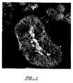
- Figure 1 shows a photomicrograph, at magnification of 10,000x, of an embodiment of the composite material.
- the composite material comprises a particle of positive electrode material 1, and a nickel particle 3 which is totally embedded in the particle of positive electrode material 1.
- the conductive material may comprise a plurality of conductive particles which are at least partially embedded within the particle of positive electrode material.
- the plurality of conductive particles may be isolated from one another. Alternately, at least some of the particles may be touching others so as to form a conductive network of particles.
- the conductive particles may have a variety of shapes and sizes.
- the particles may be substantially spherical.
- the particles may be elongated wherein one dimension is longer than another dimension.
- the particles may be ellipsoidal or cylindrical.
- the particles may be in the form of threadlike fibers.
- These elongated particles may have an average length which is less than or equal to about 10 microns. As well they may have an average diameter of less than or equal to about 1.0 micron. These sizes are merely reference points and may be varied within the scope of the invention.
- An example of conductive particles are the INCO T-210 nickel particles.
- the INCO T-210 nickel particles have a particle morphology with an average sub-micron Fisher diameter of about .9 microns, an apparent density of about .6 grams per cm 3 , and a BET of about 1.75 m 2 /g.
- the conductive material may take the form of a conductive network.
- the conductive network may have various topologies.
- One example of a conductive network is a lattice structure which may be formed by the interconnection of conductive particles, fibers, strands, and the like.
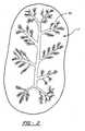
- Another example of a conductive network is the branching tree-like structure that is shown in Figure 2 .
- the conductive network 3A branches out throughout the active positive electrode particle 1.
- Another example of a conductive network is one comprising one or more carbon nanotubes and/or fullerenes.
- the embedded conductive material serves one or both of two possible roles in the composite material.
- the conductive material serves as an electronically conductive pathway through the active positive electrode material, thereby increasing the useable capacity of the active material.
- the internal conductive pathway also improves the ionic transport within the active material and prevents portions of the active material from becoming electrically isolated by reducing the transport distance through the active material and/or optimizing alignment of crystallite pathways.
- NiOOH oxidized nickel oxyhydroxide
- Ni(OH) 2 highly resistive nickel hydroxide
- the present invention overcomes such electronic isolation and ionic transport limitations.
- electronic isolation of the active material is reduced or avoided by providing an electronically conductive pathway in the interior of the nickel hydroxide particles. This allows for added electronic pathways which reduce or prevent isolation of the active material by the more resistive reduced nickel hydroxide material.
- the second role that the conductive material, such as the nickel particle 3, may play is that of a nucleation site for the growth of nickel hydroxide crystallites.
- the particles of nickel hydroxide material comprise crystallites, and the nickel particle 3 behaves as a "nucleating particle" (i.e., a nucleation site for the growth of the nickel hydroxide crystallites).
- the nickel particle 3 may orient the nickel hydroxide crystallites as they deposit onto the nickel particle during precipitation.
- the nickel particle 3 may also influence the size and/or shape of the nickel hydroxide crystallites.
- Each nickel hydroxide particle is composed of many very fine crystallites which may have an improved crystallographic orientation within the boundary of the crystallite.
- the protonic conductivity (i.e., the conductivity of protons) in a typical nickel hydroxide particle is dominated by (1) conduction within crystallites and (2) conduction across the grain boundaries between adjacent crystallites.
- the crystallite size is too large, the fully discharged nickel hydroxide does not have enough vacancies, created at the grain boundaries for the initial charging current to provide for a proton to hop from one vacancy to another vacancy, and therefore such large crystallites provide for relatively poor conductivity.
- the crystallite size is too small, the adjacent crystal lattice conduction networks will not be aligned due to the presence of too many grain boundary vacancies for the protons to hop across and protonic conductivity is thereby impeded.
- the crystallites are believed to require proper orientation to be highly conductive. That is, if there are discontinuities in the crystallite orientation from one crystallite to another then the crystallites that are improperly oriented for lower resistance current flow will dominate the resistance of the material. Conversely, if all of the crystallites are properly oriented, the conductivity of the nickel hydroxide material may be increased. The inventors believe that the nickel particle 3 may preferentially orient the crystallites of nickel hydroxide in this highly conductive orientation as they deposit, such that the nickel hydroxide has a higher protonic conductivity than nickel hydroxide deposited in a random manner.
- nucleation sites alter the size and/or shape of the crystallites.
- crystallites would have a spherical shape, while in the present invention the crystallites could have a more elongated shape.
- protonic conduction is preferential along the 101 axis of the nickel hydroxide.
- the role of the nucleation sites could be to reduce the distance along the 101 plane to the crystallite boundary or to orient the 101 planes from one crystallite to an other for enhance conduction.
- an embodiment of the present invention is a composite positive electrode material comprising a particle of active positive electrode material (such as nickel hydroxide), and a "nucleating particle" which is totally embedded within the particle of positive electrode material.
- the nucleating particle does not have to be an electrically conductive material. Instead, the nucleating particle need only provide a nucleation site for the growth of crystallites forming from the positive electrode material.- As discussed above, the addition of nucleation sites may orient the deposited crystallites of the positive electrode material such that the conductivity of the material is increased. The nucleation sites may provide for the proper deposition surface to orient the crystallites as well as to determine the average size and/or shape of the crystallites so as to increase the conductivity of the material.
- the nucleating particles are not limited to any specific shape, size or topology. Examples of shapes include, but not limited to, substantially spherical, substantially flat, elongated, cylindrical, ellipsoidal, fiber-like, cubic, parallelopiped, etc. As well, the surfaces of the nucleating particles may be varied to effect the growth of the positive electrode material crystals. For example, the nucleating particles may be partially etched to provide either a roughened surface or an oxide free surface.
- nucleation structure having a more complex topology that a single nucleating particle and which also acts as a surface for the growth of crystals of positive electrode material.
- the nucleation structure may be a plurality of connected nucleating particles.
- the nucleation structure may have the form of a lattice such as a matrix, screen or foam.
- the nucleation structure may have a topology similar to that of the conductive network shown in Figure 2 .
- the nucleation structure may have a topology sufficient to increase the conductivity of the positive electrode material by appropriately orienting the growth of the crystals and/or appropriately determining the size of the crystals and/or the shape of the crystals.
- the active positive electrode material used in the present invention may be may be any type of positive electrode material known in the art. Examples include nickel hydroxide material and manganese hydroxide material. It is within invention that any and all kinds of nickel hydroxide, or positive materials in general, may be used. Even pure nickel hydroxide without cobalt, a material with poor conductivity for commercial application, may be transformed into a viable positive electrode material via the internally embedded nickel particles or fibers described herein.
- the nickel hydroxide material may be a disordered material.
- disordered materials allow for permanent alteration of the properties of the material by engineering the local and intermediate range order. The general principals are discussed in U.S. Patent No. 5,348,822 .
- the nickel hydroxide material may be compositionally disordered. "Compositionally disordered” as used herein is specifically defined to mean that this material contains at least one compositional modifier and/or a chemical modifier. Also, the nickel hydroxide material may also be structurally disordered.
- Structurally disordered as used herein is specifically defined to mean that the material has a conductive surface and filamentous regions of higher conductivity, and further, that the material has multiple or mixed phases where alpha, beta, and gamma-phase regions may exist individually or in combination.
- the nickel hydroxide material may comprise a compositionally and structurally disordered multiphase nickel hydroxide host matrix which includes at least one modifier chosen from the group consisting of Al, Ba, Bi, Ca, Co, Cr, Cu, F, Fe, In, K, La, Li, Mg, Mn, Na, Nd, Pb, Pr, Ru, Sb, Sc, Se, Sn, Sr, Te, Ti, Y, and Zn.
- at least one modifier chosen from the group consisting of Al, Ba, Bi, Ca, Co, Cr, Cu, F, Fe, In, K, La, Li, Mg, Mn, Na, Nd, Pb, Pr, Ru, Sb, Sc, Se, Sn, Sr, Te, Ti, Y, and Zn.
- the nickel hydroxide material comprises a compositionally and structurally disordered multiphase nickel hydroxide host matrix which includes at least three modifiers chosen from the group consisting of Al, Ba, Bi, Ca, Co, Cr, Cu, F, Fe, In, K, La, Li, Mg, Mn, Na, Nd, Pb, Pr, Ru, Sb, Sc, Se, Sn, Sr, Te, Ti, Y, and Zn.
- modifiers chosen from the group consisting of Al, Ba, Bi, Ca, Co, Cr, Cu, F, Fe, In, K, La, Li, Mg, Mn, Na, Nd, Pb, Pr, Ru, Sb, Sc, Se, Sn, Sr, Te, Ti, Y, and Zn.
- the nickel hydroxide materials may be multiphase polycrystalline materials having at least one gamma-phase that contain compositional modifiers or combinations of compositional and chemical modifiers that promote the multiphase structure and the presence of gamma-phase materials.
- compositional modifiers are chosen from the group consisting of Al, Bi, Co, Cr, Cu, Fe, In, LaH 3 , Mg, Mn, Ru, Sb, Sn, TiH 2 , TiO, Zn.
- at least three compositional modifiers are used.
- the nickel hydroxide materials may include the non-substitutional incorporation of at least one chemical modifier around the plates of the material.
- the phrase "non-substitutional incorporation around the plates", as used herein means the incorporation into interlamellar sites or at edges of plates.
- chemical modifiers are preferably chosen from the group consisting of Al, Ba, Ca, Co, Cr, Cu, F, Fe, K, Li, Mg, Mn, Na, Sr, and Zn.
- the nickel hydroxide materials do not have distinct oxidation states such as 2 + , 3 + , or 4 + . Rather, these materials form graded systems that pass 1.0 to 1.7 and higher electrons.
- the nickel hydroxide material may comprise a solid solution nickel hydroxide material having a multiphase structure that comprises at least one polycrystalline gamma-phase including a polycrystalline gamma-phase unit cell comprising spacedly disposed plates with at least one chemical modifier incorporated around said plates, said plates having a range of stable intersheet distances corresponding to a 2 + oxidation state and a 3.5 + , or greater, oxidation state; and at least three compositional modifiers incorporated into the solid solution nickel hydroxide material to promote the multiphase structure.
- This embodiment is fully described in commonly assigned U.S. Patent No. 5,348,822 .
- one of the chemical modifiers is chosen from the group consisting of Al, Ba, Ca, Co, Cr, Cu, F, Fe, K, Li, Mg, Mn, Na, Sr, and Zn.
- the compositional modifiers may be chosen from the group consisting of a metal, a metallic oxide, a metallic oxide alloy, a metal hydride, and a metal hydride alloy.
- the compositional modifiers are chosen from the group consisting of Al, Bi, Co, Cr, Cu, Fe, In, LaH 3 , Mn, Ru, Sb, Sn, TiH 2 , TiO, and Zn.
- one of the compositional modifiers is chosen from the group consisting of Al, Bi, Co, Cr, Cu, Fe, In, LaH 3 , Mn, Ru, Sb, Sn, TiH 2 , TiO, and Zn.
- one of the compositional modifiers is Co.
- two of the compositional modifiers are Co and Zn.
- the nickel hydroxide material may contain 5 to 30 atomic percent, and preferable 10 to 20 atomic percent, of the compositional or chemical modifiers described above.
- the disordered nickel hydroxide electrode materials may include at least one structure selected from the group consisting of (i) amorphous; (ii) microcrystalline; (iii) polycrystalline lacking long range compositional order; and (iv) any combination of these amorphous, microcrystalline, or polycrystalline structures.
- a general concept of the present invention is that a disordered active material can more effectively accomplish the objectives of multi-electron transfer, stability on cycling, low swelling, and wide operating temperature than prior art modifications.
- the nickel hydroxide material may be a structurally disordered material comprising multiple or mixed phases where alpha, beta, and gamma-phase region may exist individually or in combination and where the nickel hydroxide has a conductive surface and filamentous regions of higher conductivity.
- electrolytes where the electrolyte comprises at least one element chosen from the group consisting of Ba, Ca, Cs, K, Li, Na, Ra, Rb, and Sr, combined with at least one member of the group consisting of Br, Cl, F, OH.
- electrolytes are formulations of KOH, NaOH, LiOH and/or CsF, and KOH and CsOH.
- Also disclosed herein is a method for producing a composite positive electrode material comprising a particle of positive electrode material, and a conductive material totally embedded within the particle of positive electrode material.
- the general method for making the composite material is by precipitation of a positive electrode material (such as the nickel hydroxide material) onto the conductive material suspended in a precipitation bath.
- the specific method can be varied widely, as will be described hereinbelow, as long as the positive electrode material is deposited onto the conductive material.
- the method requires a source of metal ion solution, a source of the conductive material, and a source of caustic (sodium hydroxide) be provided.
- the method comprises the step of combining the metal ion solution, the caustic solution and the conductive material so that a precipitation solution which includes the composite positive electrode material is formed.
- a major proportion of the metal ion solution should include the active materials main metal ion, for instance nickel ions, for deposition of a nickel hydroxide material. While nickel ions are typically used, manganese ions (for deposition of a manganese hydroxide solution) may also be used. Also, other metal ions may be added to the metal ion solution to modify and enhance the performance of the nickel hydroxide material.
- the metal ion solution may further comprise one or more metal ions selected from the group consisting of Al, Ba, Bi, Ca, Co, Cr, Cu, Fe, In, K, La, Li, Mg, Mn, Na, Nd, Pb, Pr, Ru, Sb, Sc, Se, Sn, Sr, Te, Ti, Y, and Zn.
- the metal ion solution may be selected from the group consisting of a metal sulfate solution, a metal nitrate solution, and mixtures thereof.
- the caustic solution is generally a very concentrated sodium hydroxide solution, and is standard in the art of nickel hydroxide precipitation. As with prior art precipitation processes, the sodium hydroxide can be partially replaced by hydroxides of other alkali metal hydroxides, as long as they are soluble.
- the method of producing the composite material comprises the step of mixing the conductive material with the metal ion solution to form a suspension.
- the suspension is then mixed with the caustic solution in a reactor vessel.
- the conductive material is suspended in the metal ion solution before being mixed with the caustic.
- the conductive material is preferably nickel particles (which may be fibers). It is noted that while the remaining discussion of the method of making the composite material is in terms of nickel particles, all types of conductive materials (as discussed hereinabove) may be used.
- the nickel particles act as nucleation sites for the precipitation of the positive electrode active material (hereinafter nickel hydroxide material).
- the caustic solution is then mixed with the suspension to precipitate the nickel hydroxide material onto the nickel particle, thereby forming the deposit. As the nickel hydroxide deposits onto the nickel particle, the nickel particle becomes totally in the nickel hydroxide material.
- the inventors have noted the preferred aspect of adding the nickel particles to the reactor vessel by first suspending the nickel particles in the metal ion solution, especially when the metel ion solution is predominately a nickel sulfate solution. When added in this manner, nucleation and precipitation proceeded excellently.
- the metal ion solution was also predominately a nickel sulfate solution
- the nickel particles were added independently to the reactor vessel. This case was unsuccessful, resulting in clumped metallic nickel particles outside of the nickel hydroxide. While not wishing to be bound by theory, the inventors believe that suspending the nickel particles in the metal ion solution may be preferred due to the acidic nature of the sulfate solution.
- nickel particles are partially etched, providing either a roughened surface or an oxide free surface better for nucleation.
- ammonium hydroxide is added to form a nickel ammonia complex (discussed below)
- the nickel ammonia complex which forms just prior to or simultaneous with the precipitation assists or promotes the desirable nucleation. It is still possible that direct introduction of the nickel particles to the precipitation reactor could work through the use of a wetting agent or other means.
- a source of ammonium hydroxide is also provided.
- the ammonium hydroxide is mixed with the metal ion solution to form an amine complex with the metal ions.
- the amine complex is then reacted with the caustic solution to form the nickel hydroxide material.
- the step of mixing the ammonium hydroxide solution with the metal ion solution may occur before or concurrent with the step of mixing the metal ion solution and the nickel particles.
- the step of mixing the ammonium hydroxide solution with the metal ion solution may also occur after the step of mixing the metal ion solution and the nickel particles, but before the step of mixing the caustic solution with the suspension.
- the step of mixing the ammonium hydroxide solution with the metal ion solution may occur concurrent with the step of mixing the caustic solution with the suspension.
- the method of the present invention may further comprise the step of separating the composite positive electrode material from the precipitation solution.
- the composite positive electrode material may be washed with deionized water and/or caustic solution.
- the concentrations of the solutions are variable and generally known in the art.
- the nickel particles may form about 0.1% to about 35% by weight of the final nickel hydroxide powder. Present results indicate that the effect of the added nickel particles can be seen to start at about 2% by weight of nickel particles. After about 20% by weight, the reduction in active material is not compensated for by either the increase in conductivity or the decrease in isolated active material. More preferably, the nickel particles form about 2% to about 10% by weight of the nickel hydroxide powder.
- a composite nickel hydroxide material was prepared by mixing a metal ion solution, a calcium nitrate solution, a caustic solution of NaOH, and an ammonium hydroxide solution in a reactor vessel.
- the metal ion solution was prepared by adding 177 grams of CoSO 4 , 15.5 grams MgSO 4 and 11.2 grams of ZnSO 4 to 0.219 liter (0.058 gallons) of water and 4.731 liters (1.25 gallons) of NiSO 4 solution. About 50 grams of the INCO T-210 nickel powder was added to the metal ion solution as a source of metallic nickel particles and continuously stirred.
- the metal ion solution is added to the reactor vessel at a rate of about 0.219 liter (0.058 gallons) per hour.
- a solution of 66% calcium nitrate is concurrently added to the reactor vessel at a rate of about 0.00946 liter (0.0025 gallons) per hour.
- Ammonium hydroxide is added to the reaction vessel at a rate of about 0.06 liter ( 0.016 gallons) per hour.
- a caustic solution comprising about 3.633 liters (0.96 gallons) of a 6.5M solution of NaOH is added to reaction vessel at a rate which is sufficient to keep the pH of the reaction vessel at about 11.3.
- the reaction vessel is kept at a temperature of about 60°C and is stirred at a rate of about 670 revolution per minute.
- the quantities of metal ion solution, calcium nitrate, caustic, and ammonium hydroxide used are sufficient to produce about 1 Kg of the composite nickel hydroxide material over a 24 hour period of time. After the composite nickel hydroxide material is formed, it is rinsed with deionized water or dilute caustic, and dried.
- a method for producing a composite positive electrode material comprising particles of active positive electrode material having nucleating particles totally embedded therein according to claim 4.
- the method comprises the step of combining a metal ion solution, a caustic solution, and the nucleating particles, whereby a precipitation solution including the composite positive electrode material is formed.
- the method for producing the composite positive electrode material with nucleating particles is the same as the method discussed above with. regards to using the conductive material.
- Nucleating particles (which need not be conductive) are used instead of the conductive material.
- the nucleating particles may be electrically conductive particles such as nickel particles.
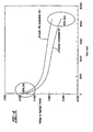
- Figure 3 shows the AC impedance measurements for positive electrodes comprising two different positive electrode materials.
- the AC impedance measurements of a positive electrode is a plot showing the real portion of electrode impedance on the horizontal axis and the imaginary portion of electrode impedance on the vertical axis.
- the impedances are plotted as a function of a range of frequencies starting at a high frequency of about 10 kHz and going to a low frequency of about 20 uHz.
- Plot A is the AC impedance measurements of a positive electrode comprising a nickel hydroxide active material.
- Plot B is the AC impedance measurement of a positive electrode comprising the composite positive electrode material of the present invention.
- the composite material comprises the same nickel hydroxide active material (from which Plot A was made) with the addition of about 5% by weight of embedded nickel particles.
- a n important electrical parameter of a battery electrode is the "charge transfer resistance", R CT .
- the charge transfer resistance is calculated from the nyquist plot describing the AC impedance of the electrode over a range of frequencies.
- the charge transfer resistance corresponds to the diameter of the "high frequency semicircle" of the AC impedance plot multiplied by the number of grams of positive electrode material. Referring to Figure 3 , this diameter is denoted as Diam(A) for Plot A and Diam(B) for Plot B.
- the Diam(A) was measured to be about .113 ohms while the number of grams of the positive electrode material (nickel hydroxide without embedded nickel) was about 2.85 grams.
- the charge transfer resistance R CT (A) of the nickel hydroxide material without embedded nickel was about .322 ohms-gram.
- the diameter of the semi-circle of Plot B, Diam(B) was measured to be about .062 ohms while the number of grams of the positive electrode material (the same nickel hydroxide material with 5% embedded Ni) was about 2.94 grams.
- the charge transfer resistance R CT (B) of the nickel hydroxide material with the 5% embedded nickel fibers was about .182 ohms-gram.
- the charge transfer resistance for the nickel hydroxide material with embedded nickel, R CT (B) was significantly lower than the charge transfer resistance for the nickel hydroxide material without the embedded nickel R CT (A).
- the addition of the nickel particles to the nickel hydroxide material may lower the charge transfer resistance of the positive electrode material by over 50%.
- a positive electrode material characterized by a charge transfer resistance less than about' .22 ohms-gram.
- the positive electrode material has a charge transfer resistance is less than about .20 ohms-gram.
- the charge transfer resistance is less than about .19 ohms-gram.
- FIG. 4 shows positive electrode discharge curves A and B.
- the discharge curves A, B show the positive electrode half cell potentials relative to an Hg/HgO reference electrode. The potentials are given from about 95% state of charge to about 50% state of charge.
- Discharge curve A is for a positive electrode having an active electrode material which comprises a nickel hydroxide material without any embedded nickel particles.
- Discharge curve B is for a positive electrode having an active material comprising the same nickel hydroxide material with about 5% by weight of embedded nickel fibers (i.e., about 5% of the INCO T-210 nickel particles).
- Comparison of the discharge curves shows that the addition of the nickel fibers increases the half cell potential of the positive electrode over the entire range of state of discharge (i.e., from 95% to 50%). Though not wishing to be bound by theory, it is believed that the increased potential is at least partially due to the decreased charge transfer resistance discussed above.
- Positive electrodes were prepared for half-cell testing by pasting a slurry of about 5% by weight of Co metal, about 5% by weight of CoO with PVA binder and the remainder active material onto foam metal substrates.
- the respective electrode samples included approximately 2 grams of active material paste (including binder and external additives, but not including the foam metal substrate) and were tested in an excess electrolyte configuration with the following results.
- Sample A is a nickel hydroxide positive electrode material without any embedded nickel fibers.
- Sample B is the same nickel hydroxide material with about 5% by weight of the embedded nickel fibers (5% of INCO T-210 nickel particles).
- “Commercial” is a commercially available material. The capacities of the positive electrode materials are shown- in the Table below. Table Sample mAh/g Commercial 230 A (without embedded nickel) 276 B (with 5% embedded nickel) 292 As can be seen from the Table, the inclusion of the 5% nickel fibers in the nickel hydroxide material greatly enhances the utilization and capacity of the active material.
- the composite positive electrode material of the present invention may provide for a "fully pasted positive electrode” that does not use a foam or fiber skeleton or substrate.
- this embodiment is formed from a standard nickel hydroxide material with externally conductive additives and a plastic binder.
- the composite electrode material of the present invention could provide the improved power and rate discharge needed for practical commercialization of this type of electrode.
- substrate as used herein relates to any electrically conductive support for the active positive electrode material. It may take the form of a foam, grid, plate, foil, expanded metal or any other type of support structure. It may take the form of conventional nickel foils, plates and foams, as well as, carbon networks, fibers or particulate and cobalt oxyhydroxide networks. It may be made from any electronically conductive material. Preferably, it is made from a metal such as nickel or a nickel alloy. More preferably, the substrate for the positive electrode is a nickel foam.
Landscapes
- Chemical & Material Sciences (AREA)
- Chemical Kinetics & Catalysis (AREA)
- Electrochemistry (AREA)
- General Chemical & Material Sciences (AREA)
- Engineering & Computer Science (AREA)
- Inorganic Chemistry (AREA)
- Manufacturing & Machinery (AREA)
- Materials Engineering (AREA)
- Battery Electrode And Active Subsutance (AREA)
Applications Claiming Priority (3)
| Application Number | Priority Date | Filing Date | Title |
|---|---|---|---|
| US135460 | 1998-08-17 | ||
| US09/135,460 US6177213B1 (en) | 1998-08-17 | 1998-08-17 | Composite positive electrode material and method for making same |
| EP99939133.7A EP1116287B1 (en) | 1998-08-17 | 1999-08-11 | Composite positive electrode material and method for making same |
Related Parent Applications (2)
| Application Number | Title | Priority Date | Filing Date |
|---|---|---|---|
| EP99939133.7A Division EP1116287B1 (en) | 1998-08-17 | 1999-08-11 | Composite positive electrode material and method for making same |
| EP99939133.7 Division | 1999-08-11 |
Publications (3)
| Publication Number | Publication Date |
|---|---|
| EP1496555A2 EP1496555A2 (en) | 2005-01-12 |
| EP1496555A3 EP1496555A3 (en) | 2010-03-24 |
| EP1496555B1 true EP1496555B1 (en) | 2013-06-19 |
Family
ID=22468210
Family Applications (2)
| Application Number | Title | Priority Date | Filing Date |
|---|---|---|---|
| EP99939133.7A Expired - Lifetime EP1116287B1 (en) | 1998-08-17 | 1999-08-11 | Composite positive electrode material and method for making same |
| EP04024169.7A Expired - Lifetime EP1496555B1 (en) | 1998-08-17 | 1999-08-11 | Composite positive electrode material and method for making same |
Family Applications Before (1)
| Application Number | Title | Priority Date | Filing Date |
|---|---|---|---|
| EP99939133.7A Expired - Lifetime EP1116287B1 (en) | 1998-08-17 | 1999-08-11 | Composite positive electrode material and method for making same |
Country Status (12)
| Country | Link |
|---|---|
| US (4) | US6177213B1 (enExample) |
| EP (2) | EP1116287B1 (enExample) |
| JP (4) | JP3578992B2 (enExample) |
| KR (2) | KR20060105055A (enExample) |
| AU (1) | AU759414B2 (enExample) |
| BR (1) | BR9913060A (enExample) |
| CA (1) | CA2339211A1 (enExample) |
| MX (1) | MX216887B (enExample) |
| NO (1) | NO20010772L (enExample) |
| RU (1) | RU2208270C2 (enExample) |
| TW (1) | TW432739B (enExample) |
| WO (1) | WO2000010212A1 (enExample) |
Families Citing this family (50)
| Publication number | Priority date | Publication date | Assignee | Title |
|---|---|---|---|---|
| US6177213B1 (en) * | 1998-08-17 | 2001-01-23 | Energy Conversion Devices, Inc. | Composite positive electrode material and method for making same |
| JP3744716B2 (ja) * | 1999-03-30 | 2006-02-15 | 三洋電機株式会社 | 密閉型アルカリ蓄電池 |
| CN1127163C (zh) * | 1999-04-05 | 2003-11-05 | 深圳市比亚迪股份有限公司 | 高温镍氢电池及其制造方法 |
| US7132161B2 (en) * | 1999-06-14 | 2006-11-07 | Energy Science Laboratories, Inc. | Fiber adhesive material |
| US20040009353A1 (en) * | 1999-06-14 | 2004-01-15 | Knowles Timothy R. | PCM/aligned fiber composite thermal interface |
| US6913075B1 (en) * | 1999-06-14 | 2005-07-05 | Energy Science Laboratories, Inc. | Dendritic fiber material |
| GB9919807D0 (en) * | 1999-08-21 | 1999-10-27 | Aea Technology Plc | Anode for rechargeable lithium cell |
| JP2001266886A (ja) | 2000-03-21 | 2001-09-28 | Matsushita Electric Ind Co Ltd | アルカリ蓄電池用非焼結式正極およびアルカリ蓄電池 |
| DE10025761A1 (de) * | 2000-05-25 | 2001-11-29 | Merck Patent Gmbh | Dotiertes Anodenmaterial in elektrochemischen Zellen |
| US6740451B2 (en) | 2001-12-20 | 2004-05-25 | The Gillette Company | Gold additive for a cathode including nickel oxyhydroxide for an alkaline battery |
| DE10220486C1 (de) * | 2002-05-07 | 2003-09-18 | Nbt Gmbh | Alkalischer Akkumulator |
| US7172710B2 (en) * | 2003-03-03 | 2007-02-06 | Ovonic Battery Company, Inc. | Performance enhancing additive material for the nickel hydroxide positive electrode in rechargeable alkaline cells |
| US7201857B2 (en) * | 2003-03-03 | 2007-04-10 | Texaco Ovonic Battery Systems, Llc | Performance enhancing additive material for the nickel hydroxide positive electrode in rechargeable alkaline cells |
| US6830725B2 (en) * | 2003-04-01 | 2004-12-14 | Texaco Ovonic Battery Systems, Llc | Hydrogen storage alloys having a high porosity surface layer |
| WO2004112116A1 (ja) * | 2003-06-16 | 2004-12-23 | Sumitomo Electric Industries, Ltd. | 窒化物半導体結晶表面の加工方法およびその方法により得られた窒化物半導体結晶 |
| US7250386B2 (en) * | 2003-07-18 | 2007-07-31 | Energy Conversion Devices, Inc. | Quantum limit catalysts and hydrogen storage materials |
| KR100595896B1 (ko) * | 2003-07-29 | 2006-07-03 | 주식회사 엘지화학 | 리튬 이차 전지용 음극 활물질 및 그의 제조 방법 |
| TW200520292A (en) | 2003-08-08 | 2005-06-16 | Rovcal Inc | High capacity alkaline cell |
| US20060257728A1 (en) * | 2003-08-08 | 2006-11-16 | Rovcal, Inc. | Separators for use in alkaline cells having high capacity |
| CN101019252A (zh) * | 2003-12-10 | 2007-08-15 | 罗福科公司 | 采用阴极补充剂的高容量碱性电池 |
| US7211541B2 (en) * | 2003-12-11 | 2007-05-01 | Ovonic Hydrogen Systems Llc | Mg—Ni hydrogen storage composite having high storage capacity and excellent room temperature kinetics |
| AR047875A1 (es) * | 2004-06-04 | 2006-03-01 | Rovcal Inc | Celdas alcalinas que presentan alta capacidad |
| US20060083927A1 (en) * | 2004-10-15 | 2006-04-20 | Zyvex Corporation | Thermal interface incorporating nanotubes |
| RU2306637C2 (ru) * | 2005-08-08 | 2007-09-20 | Федеральное государственное унитарное предприятие УРАЛЬСКИЙ ЭЛЕКТРОХИМИЧЕСКИЙ КОМБИНАТ | Способ стабилизации пасты активной массы при изготовлении электродной ленты |
| FR2890784B1 (fr) * | 2005-09-09 | 2013-05-24 | Accumulateurs Fixes | Electrode positive pour accumulateur alcalin |
| JP2008250225A (ja) * | 2007-03-30 | 2008-10-16 | Powdertech Co Ltd | 電子写真用フェライトキャリアコア材の品質測定法 |
| JP5874328B2 (ja) * | 2010-11-29 | 2016-03-02 | 住友化学株式会社 | 電極合剤ペースト、電極および非水電解質二次電池 |
| RU2475896C2 (ru) * | 2011-05-05 | 2013-02-20 | Михаил Валерьевич Морозов | Способ получения никелевой волоконной электродной основы с развитой поверхностью волокон для химических источников тока и полученная этим способом никелевая волоконная основа электрода |
| JP6090673B2 (ja) | 2012-09-28 | 2017-03-08 | 株式会社Gsユアサ | アルカリ蓄電池とアルカリ蓄電池用の正極材 |
| KR20140095810A (ko) | 2013-01-25 | 2014-08-04 | 삼성에스디아이 주식회사 | 리튬 이차 전지용 양극 활물질 및 이를 포함하는 리튬 이차 전지 |
| CN104347850A (zh) * | 2013-07-25 | 2015-02-11 | 苏州宝时得电动工具有限公司 | 电极复合材料及其制备方法、正极、具有该正极的电池 |
| US9935315B2 (en) | 2015-02-05 | 2018-04-03 | Basf Corporation | Nickel hydroxide positive electrode for alkaline rechargeable battery |
| US9899676B2 (en) | 2015-02-05 | 2018-02-20 | Basf Corporation | Nickel hydroxide positive electrode for alkaline rechargeable battery |
| WO2016126622A1 (en) * | 2015-02-05 | 2016-08-11 | Basf Corporation | Nickel hydroxide positive electrode for alkaline rechargeable battery |
| US10587012B2 (en) | 2015-03-26 | 2020-03-10 | Basf Corporation | Electrolyte compositions comprising ionic liquids and metal hydride batteries comprising same |
| JP2017033669A (ja) * | 2015-07-29 | 2017-02-09 | ニッポン高度紙工業株式会社 | 電池正極用活物質、電池、電池正極用活物質の製造方法 |
| CN108886175B (zh) | 2016-03-28 | 2022-08-02 | 巴斯夫公司 | 用于再充式电池组的硅基固体电解质 |
| KR102047351B1 (ko) * | 2016-04-27 | 2019-11-21 | 드 노라 페르멜렉 가부시키가이샤 | 전해조 |
| US11898258B2 (en) | 2018-05-21 | 2024-02-13 | B. G. Negev Technologies & Applications Ltd., At Ben-Gurion University | Electrochemical oxidation of methane to methanol |
| JP7695998B2 (ja) | 2020-12-29 | 2025-06-19 | カワサキモータース株式会社 | プロトン伝導型二次電池で用いるバルクSi負極 |
| WO2022145031A1 (en) | 2020-12-29 | 2022-07-07 | Kawasaki Motors, Ltd. | Processes of hydrogen annealing of si-surfaces |
| WO2022145030A1 (en) | 2020-12-29 | 2022-07-07 | Kawasaki Motors, Ltd. | Salt containing electrolytes that promote the formation of proton-conducting rechargeable batteries |
| WO2022145027A1 (en) | 2020-12-29 | 2022-07-07 | Kawasaki Motors, Ltd. | Ionic liquid electrolytes including salt additives for use in proton-conducting rechargeable batteries |
| WO2022145029A1 (en) | 2020-12-29 | 2022-07-07 | Kawasaki Motors, Ltd. | Group 14 element-containing metal hydride with a superlattice structure for use in hydrogen storage. |
| WO2022145026A1 (en) | 2020-12-29 | 2022-07-07 | Kawasaki Motors, Ltd. | Si-containing alloy for the anode of proton-conducting rechargeable batteries |
| WO2022145028A1 (en) | 2020-12-29 | 2022-07-07 | Kawasaki Motors, Ltd. | Group 14 element-containing metal hydrides with a superlattice structure for use in proton-conducting rechargeable batteries |
| JP7697047B2 (ja) | 2021-05-13 | 2025-06-23 | カワサキモータース株式会社 | プロトンおよび水酸化物イオン伝導性ポリマーベースのセパレータを備えるバイポーラ電池 |
| KR20240023632A (ko) | 2021-06-21 | 2024-02-22 | 가와사키 모터스 가부시키가이샤 | 프로톤 전도성 충전지 및 방법 |
| WO2023007751A1 (en) | 2021-07-30 | 2023-02-02 | Kawasaki Motors, Ltd. | Si-containing metal hydrides with expanded superlattice structure for use in proton-conducting rechargeable electrochemical cells |
| CN116981787B (zh) * | 2023-05-19 | 2025-11-14 | 广东邦普循环科技有限公司 | 电化学脱嵌控制方法、系统、控制单元、设备及存储介质 |
Family Cites Families (51)
| Publication number | Priority date | Publication date | Assignee | Title |
|---|---|---|---|---|
| US3945847A (en) * | 1971-12-28 | 1976-03-23 | Union Carbide Corporation | Coherent manganese dioxide electrodes, process for their production, and electrochemical cells utilizing them |
| US3933520A (en) * | 1975-04-03 | 1976-01-20 | The United States Of America As Represented By The United States Energy Research And Development Administration | Method of preparing electrodes with porous current collector structures and solid reactants for secondary electrochemical cells |
| US4048715A (en) * | 1976-01-27 | 1977-09-20 | The United States Of America As Represented By The United States Energy Research And Development Administration | Method of preparing porous, active material for use in electrodes of secondary electrochemical cells |
| US4029860A (en) * | 1976-02-12 | 1977-06-14 | The United States Of America As Represented By The United States Energy Research And Development Administration | Compartmented electrode structure |
| FR2421156A1 (fr) * | 1978-03-30 | 1979-10-26 | Commissariat Energie Atomique | Procede de preparation d'une piece en ceramique, comportant sur sa surface des inclusions de materiau conducteur de l'electricite |
| JPH0622113B2 (ja) | 1984-05-28 | 1994-03-23 | 松下電器産業株式会社 | アルカリ蓄電池用ニツケル正極およびその製造法 |
| JPS63138646A (ja) * | 1986-11-29 | 1988-06-10 | Toshiba Battery Co Ltd | 円筒形非水電解液電池 |
| JPS63195962A (ja) * | 1987-02-09 | 1988-08-15 | Matsushita Electric Ind Co Ltd | 電池 |
| JPH07107848B2 (ja) * | 1987-06-02 | 1995-11-15 | 松下電器産業株式会社 | アルカリ蓄電池用非焼結式正極 |
| JPS6459765A (en) * | 1987-08-28 | 1989-03-07 | Matsushita Electric Industrial Co Ltd | Alkaline manganese battery |
| JPH0724218B2 (ja) * | 1988-04-11 | 1995-03-15 | 株式会社ユアサコーポレーション | アルカリ電池用ニッケル電極及びこれを用いた電池 |
| DE68917045T2 (de) | 1988-07-19 | 1995-03-16 | Yuasa Battery Co Ltd | Nickelelektrode für eine alkalische Batterie. |
| JPH0393161A (ja) * | 1989-09-04 | 1991-04-18 | Matsushita Electric Ind Co Ltd | 電池用ニッケル正極及びその製造法 |
| JPH03149753A (ja) * | 1989-11-06 | 1991-06-26 | Matsushita Electric Ind Co Ltd | アルカリ電池用ニッケル極 |
| JPH044560A (ja) * | 1990-04-20 | 1992-01-09 | Hitachi Chem Co Ltd | アルカリ蓄電池用ニッケル極及びその製法 |
| US5277999A (en) | 1991-08-14 | 1994-01-11 | Ovonic Battery Company, Inc. | Electrochemical hydrogen storage alloys and batteries fabricated these alloys having significantly improved performance characteristics |
| US5569444A (en) * | 1990-06-18 | 1996-10-29 | Blanchard; Philippe | Process of obtaining a metal hydroxide powder and powder obtained by the process |
| ATE114873T1 (de) * | 1990-06-18 | 1994-12-15 | Accumulateurs Fixes | Verfahren zur herstellung eines metallischen hydroxidpulvers und auf diese weise hergestellte pulver. |
| US5106706A (en) * | 1990-10-18 | 1992-04-21 | Westinghouse Electric Corp. | Oxide modified air electrode surface for high temperature electrochemical cells |
| US5393616A (en) | 1990-10-29 | 1995-02-28 | Yuasa Corporation | Metal hydride electrode |
| US5250374A (en) * | 1991-01-24 | 1993-10-05 | Rbc Universal | Method of preparing a rechargeable modified manganese-containing material by electrolytic deposition and related material |
| JPH04269454A (ja) * | 1991-02-26 | 1992-09-25 | Matsushita Electric Ind Co Ltd | アルカリ電池用ニッケル極 |
| US5366831A (en) | 1991-06-14 | 1994-11-22 | Yuasa Corporation | Nickel electrode for alkaline battery |
| EP0571630B1 (en) | 1991-10-21 | 2002-01-30 | Yuasa Corporation | Method for production of nickel plate and alkali storage battery |
| JPH05241719A (ja) * | 1992-03-02 | 1993-09-21 | Fujitsu Ltd | 感圧方式入力装置 |
| JPH05254847A (ja) * | 1992-03-13 | 1993-10-05 | Hitachi Maxell Ltd | ニッケル電極用の水酸化ニッケル粉末の製造方法 |
| JP2530281B2 (ja) * | 1992-12-24 | 1996-09-04 | 古河電池株式会社 | アルカリ蓄電池 |
| JPH0652856A (ja) * | 1992-07-31 | 1994-02-25 | Furukawa Battery Co Ltd:The | アルカリ蓄電池用正極活物質並びにその製造法 |
| JP3438142B2 (ja) | 1992-09-18 | 2003-08-18 | 松下電器産業株式会社 | 中・大容量密閉式金属酸化物・水素蓄電池 |
| JP3097347B2 (ja) | 1992-09-18 | 2000-10-10 | 松下電器産業株式会社 | ニッケル・水素蓄電池 |
| US5567549A (en) | 1992-11-12 | 1996-10-22 | Ovonic Battery Company, Inc. | Nickel metal hydride battery containing a modified disordered multiphase nickel aluminum based positive electrode |
| US5569563A (en) | 1992-11-12 | 1996-10-29 | Ovshinsky; Stanford R. | Nickel metal hybride battery containing a modified disordered multiphase nickel hydroxide positive electrode |
| US5344728A (en) | 1992-11-12 | 1994-09-06 | Ovonic Battery Company, Inc. | Compositionally and structurally disordered multiphase nickel hydroxide positive electrode for alkaline rechargeable electrochemical cells |
| US5523182A (en) * | 1992-11-12 | 1996-06-04 | Ovonic Battery Company, Inc. | Enhanced nickel hydroxide positive electrode materials for alkaline rechargeable electrochemical cells |
| US5861225A (en) * | 1992-11-12 | 1999-01-19 | Ovonic Battery Company, Inc. | Nickel battery electrode having multiple composition nickel hydroxide active materials |
| US5348822A (en) * | 1992-11-12 | 1994-09-20 | Ovonic Battery Company, Inc. | Chemically and compositionally modified solid solution disordered multiphase nickel hydroxide positive electrode for alkaline rechargeable electrochemical cells |
| JPH06260166A (ja) * | 1993-03-03 | 1994-09-16 | Yuasa Corp | アルカリ蓄電池用ニッケル電極 |
| US5451475A (en) | 1993-04-28 | 1995-09-19 | Matsushita Electric Industrial Co., Ltd. | Nickel positive electrode for alkaline storage battery and sealed nickel-hydrogen storage battery using nickel positive electrode |
| US5506076A (en) * | 1993-06-30 | 1996-04-09 | Toshiba Battery Co., Ltd. | Alkali secondary battery |
| US5393617A (en) * | 1993-10-08 | 1995-02-28 | Electro Energy, Inc. | Bipolar electrochmeical battery of stacked wafer cells |
| JPH07114919A (ja) * | 1993-10-14 | 1995-05-02 | Toshiba Battery Co Ltd | ペースト式ニッケル極の製造方法 |
| JPH07312221A (ja) * | 1994-05-18 | 1995-11-28 | Yuasa Corp | 正極合剤 |
| JP2802482B2 (ja) * | 1994-10-28 | 1998-09-24 | 古河電池株式会社 | アルカリ二次電池用ニッケル極 |
| US6040007A (en) * | 1996-06-19 | 2000-03-21 | Tanaka Chemical Corporation | Nickel hydroxide particles having an α- or β-cobalt hydroxide coating layer for use in alkali batteries and a process for producing the nickel hydroxide |
| JPH1074514A (ja) * | 1996-09-02 | 1998-03-17 | Toyota Central Res & Dev Lab Inc | アルカリ電池用ニッケル正極活物質 |
| JPH1074513A (ja) * | 1996-09-02 | 1998-03-17 | Japan Metals & Chem Co Ltd | 水酸化ニッケル活物質およびその製造方法 |
| US5788943A (en) * | 1996-09-05 | 1998-08-04 | The Hall Chemical Company | Battery-grade nickel hydroxide and method for its preparation |
| JP3518975B2 (ja) * | 1996-09-20 | 2004-04-12 | 松下電器産業株式会社 | アルカリ蓄電池用正極およびアルカリ蓄電池 |
| JPH10247494A (ja) * | 1997-03-04 | 1998-09-14 | Japan Metals & Chem Co Ltd | 水酸化ニッケル活物質およびその製造方法 |
| JP3188853B2 (ja) * | 1997-04-01 | 2001-07-16 | セイコーインスツルメンツ株式会社 | 非水電解質二次電池 |
| US6177213B1 (en) * | 1998-08-17 | 2001-01-23 | Energy Conversion Devices, Inc. | Composite positive electrode material and method for making same |
-
1998
- 1998-08-17 US US09/135,460 patent/US6177213B1/en not_active Expired - Lifetime
-
1999
- 1999-08-11 WO PCT/US1999/018164 patent/WO2000010212A1/en not_active Ceased
- 1999-08-11 AU AU53476/99A patent/AU759414B2/en not_active Ceased
- 1999-08-11 KR KR1020067017476A patent/KR20060105055A/ko not_active Ceased
- 1999-08-11 BR BR9913060-2A patent/BR9913060A/pt not_active Application Discontinuation
- 1999-08-11 KR KR1020017001991A patent/KR100725609B1/ko not_active Expired - Lifetime
- 1999-08-11 MX MXPA01001580 patent/MX216887B/es not_active IP Right Cessation
- 1999-08-11 CA CA002339211A patent/CA2339211A1/en not_active Abandoned
- 1999-08-11 RU RU2001107121/09A patent/RU2208270C2/ru not_active IP Right Cessation
- 1999-08-11 EP EP99939133.7A patent/EP1116287B1/en not_active Expired - Lifetime
- 1999-08-11 JP JP2000565576A patent/JP3578992B2/ja not_active Expired - Fee Related
- 1999-08-11 EP EP04024169.7A patent/EP1496555B1/en not_active Expired - Lifetime
- 1999-08-20 TW TW088114217A patent/TW432739B/zh not_active IP Right Cessation
-
2000
- 2000-12-30 US US09/751,180 patent/US6348285B2/en not_active Expired - Lifetime
- 2000-12-30 US US09/751,176 patent/US6569566B2/en not_active Expired - Lifetime
- 2000-12-30 US US09/751,177 patent/US6548209B2/en not_active Expired - Lifetime
-
2001
- 2001-02-15 NO NO20010772A patent/NO20010772L/no not_active Application Discontinuation
-
2004
- 2004-02-19 JP JP2004043303A patent/JP5099960B2/ja not_active Expired - Lifetime
-
2010
- 2010-07-30 JP JP2010171955A patent/JP2010282973A/ja active Pending
-
2011
- 2011-09-15 JP JP2011201852A patent/JP5467086B2/ja not_active Expired - Lifetime
Also Published As
| Publication number | Publication date |
|---|---|
| MXPA01001580A (es) | 2002-04-08 |
| TW432739B (en) | 2001-05-01 |
| KR100725609B1 (ko) | 2007-06-08 |
| AU5347699A (en) | 2000-03-06 |
| JP3578992B2 (ja) | 2004-10-20 |
| US6177213B1 (en) | 2001-01-23 |
| RU2208270C2 (ru) | 2003-07-10 |
| MX216887B (es) | 2003-10-10 |
| US6569566B2 (en) | 2003-05-27 |
| CA2339211A1 (en) | 2000-02-24 |
| KR20010082174A (ko) | 2001-08-29 |
| JP2010282973A (ja) | 2010-12-16 |
| EP1116287A1 (en) | 2001-07-18 |
| EP1116287B1 (en) | 2013-06-26 |
| NO20010772D0 (no) | 2001-02-15 |
| JP2002522894A (ja) | 2002-07-23 |
| US6348285B2 (en) | 2002-02-19 |
| NO20010772L (no) | 2001-04-17 |
| US20010019799A1 (en) | 2001-09-06 |
| BR9913060A (pt) | 2001-05-08 |
| KR20060105055A (ko) | 2006-10-09 |
| EP1496555A2 (en) | 2005-01-12 |
| AU759414B2 (en) | 2003-04-17 |
| EP1496555A3 (en) | 2010-03-24 |
| US20010023040A1 (en) | 2001-09-20 |
| JP5099960B2 (ja) | 2012-12-19 |
| JP5467086B2 (ja) | 2014-04-09 |
| JP2004214210A (ja) | 2004-07-29 |
| JP2012023049A (ja) | 2012-02-02 |
| WO2000010212A1 (en) | 2000-02-24 |
| US6548209B2 (en) | 2003-04-15 |
| EP1116287A4 (en) | 2003-04-02 |
| US20020146505A1 (en) | 2002-10-10 |
Similar Documents
| Publication | Publication Date | Title |
|---|---|---|
| EP1496555B1 (en) | Composite positive electrode material and method for making same | |
| US6261720B1 (en) | Positive electrode active material for alkaline storage batteries | |
| US6632568B1 (en) | Non-sintered nickel electrode with excellent over-discharge characteristics, an alkaline storage cell having the non-sintered nickel electrode, and a manufacturing method of the non-sintered nickel electrode | |
| JPH10284113A (ja) | アルカリ蓄電池 | |
| JP3518975B2 (ja) | アルカリ蓄電池用正極およびアルカリ蓄電池 | |
| JP4403594B2 (ja) | アルカリ蓄電池用正極活物質およびその製造方法 | |
| JP2000003706A (ja) | アルカリ蓄電池用正極および正極活物質 | |
| JPH11213998A (ja) | アルカリ蓄電池用正極活物質 | |
| EP1719195B1 (en) | Positive electrode active material for a nickel electrode | |
| JPH10172561A (ja) | ニッケル系電池の陽極活物質及びニッケル系電池の陽極製造方法 | |
| JPH0950805A (ja) | アルカリ蓄電池用ニッケル電極及びニッケル電極用活物質並びにその製造方法、アルカリ蓄電池 | |
| JPH10172562A (ja) | 陽極用活物質、その製造方法および陽極製造方法 | |
| JP3233013B2 (ja) | アルカリ蓄電池用ニッケル極 | |
| JP2002270168A (ja) | ニッケル電極用活物質とその製造方法およびニッケル電極 | |
| JP2001325953A (ja) | アルカリ二次電池用の正極活物質、およびそれを用いたアルカリ二次電池 |
Legal Events
| Date | Code | Title | Description |
|---|---|---|---|
| PUAI | Public reference made under article 153(3) epc to a published international application that has entered the european phase |
Free format text: ORIGINAL CODE: 0009012 |
|
| 17P | Request for examination filed |
Effective date: 20041026 |
|
| AC | Divisional application: reference to earlier application |
Ref document number: 1116287 Country of ref document: EP Kind code of ref document: P |
|
| AK | Designated contracting states |
Kind code of ref document: A2 Designated state(s): DE FR GB |
|
| RIN1 | Information on inventor provided before grant (corrected) |
Inventor name: REICHMAN, BENJAMIN Inventor name: FIERRO, CRISTIAN Inventor name: OVSHINSKY, STANFORD R. Inventor name: MAYS, WILLIAM Inventor name: FETCENKO, MICHAEL A. Inventor name: YOUNG, KWO Inventor name: SOMMERS, BETH |
|
| PUAL | Search report despatched |
Free format text: ORIGINAL CODE: 0009013 |
|
| AK | Designated contracting states |
Kind code of ref document: A3 Designated state(s): DE FR GB |
|
| AKX | Designation fees paid |
Designated state(s): DE FR GB |
|
| 17Q | First examination report despatched |
Effective date: 20130129 |
|
| GRAP | Despatch of communication of intention to grant a patent |
Free format text: ORIGINAL CODE: EPIDOSNIGR1 |
|
| INTG | Intention to grant announced |
Effective date: 20130404 |
|
| GRAS | Grant fee paid |
Free format text: ORIGINAL CODE: EPIDOSNIGR3 |
|
| GRAA | (expected) grant |
Free format text: ORIGINAL CODE: 0009210 |
|
| AC | Divisional application: reference to earlier application |
Ref document number: 1116287 Country of ref document: EP Kind code of ref document: P |
|
| AK | Designated contracting states |
Kind code of ref document: B1 Designated state(s): DE FR GB |
|
| REG | Reference to a national code |
Ref country code: GB Ref legal event code: FG4D |
|
| REG | Reference to a national code |
Ref country code: DE Ref legal event code: R096 Ref document number: 69944790 Country of ref document: DE Effective date: 20130814 |
|
| PLBE | No opposition filed within time limit |
Free format text: ORIGINAL CODE: 0009261 |
|
| STAA | Information on the status of an ep patent application or granted ep patent |
Free format text: STATUS: NO OPPOSITION FILED WITHIN TIME LIMIT |
|
| 26N | No opposition filed |
Effective date: 20140320 |
|
| REG | Reference to a national code |
Ref country code: DE Ref legal event code: R097 Ref document number: 69944790 Country of ref document: DE Effective date: 20140320 |
|
| REG | Reference to a national code |
Ref country code: FR Ref legal event code: PLFP Year of fee payment: 18 |
|
| REG | Reference to a national code |
Ref country code: FR Ref legal event code: PLFP Year of fee payment: 19 |
|
| REG | Reference to a national code |
Ref country code: FR Ref legal event code: PLFP Year of fee payment: 20 |
|
| PGFP | Annual fee paid to national office [announced via postgrant information from national office to epo] |
Ref country code: FR Payment date: 20180824 Year of fee payment: 20 |
|
| PGFP | Annual fee paid to national office [announced via postgrant information from national office to epo] |
Ref country code: GB Payment date: 20180831 Year of fee payment: 20 |
|
| PGFP | Annual fee paid to national office [announced via postgrant information from national office to epo] |
Ref country code: DE Payment date: 20181031 Year of fee payment: 20 |
|
| REG | Reference to a national code |
Ref country code: DE Ref legal event code: R071 Ref document number: 69944790 Country of ref document: DE |
|
| REG | Reference to a national code |
Ref country code: GB Ref legal event code: PE20 Expiry date: 20190810 |
|
| PG25 | Lapsed in a contracting state [announced via postgrant information from national office to epo] |
Ref country code: GB Free format text: LAPSE BECAUSE OF EXPIRATION OF PROTECTION Effective date: 20190810 |