EP1491920B1 - Corps optiques multicouches - Google Patents
Corps optiques multicouches Download PDFInfo
- Publication number
- EP1491920B1 EP1491920B1 EP04021443A EP04021443A EP1491920B1 EP 1491920 B1 EP1491920 B1 EP 1491920B1 EP 04021443 A EP04021443 A EP 04021443A EP 04021443 A EP04021443 A EP 04021443A EP 1491920 B1 EP1491920 B1 EP 1491920B1
- Authority
- EP
- European Patent Office
- Prior art keywords
- optical
- layers
- pet
- optical layers
- film
- Prior art date
- Legal status (The legal status is an assumption and is not a legal conclusion. Google has not performed a legal analysis and makes no representation as to the accuracy of the status listed.)
- Expired - Lifetime
Links
- 0 CCCCCCCCCCCCCN*NCCC Chemical compound CCCCCCCCCCCCCN*NCCC 0.000 description 2
Images


Classifications
-
- B—PERFORMING OPERATIONS; TRANSPORTING
- B32—LAYERED PRODUCTS
- B32B—LAYERED PRODUCTS, i.e. PRODUCTS BUILT-UP OF STRATA OF FLAT OR NON-FLAT, e.g. CELLULAR OR HONEYCOMB, FORM
- B32B27/00—Layered products comprising a layer of synthetic resin
- B32B27/06—Layered products comprising a layer of synthetic resin as the main or only constituent of a layer, which is next to another layer of the same or of a different material
- B32B27/08—Layered products comprising a layer of synthetic resin as the main or only constituent of a layer, which is next to another layer of the same or of a different material of synthetic resin
-
- G—PHYSICS
- G02—OPTICS
- G02B—OPTICAL ELEMENTS, SYSTEMS OR APPARATUS
- G02B5/00—Optical elements other than lenses
- G02B5/08—Mirrors
-
- B—PERFORMING OPERATIONS; TRANSPORTING
- B29—WORKING OF PLASTICS; WORKING OF SUBSTANCES IN A PLASTIC STATE IN GENERAL
- B29C—SHAPING OR JOINING OF PLASTICS; SHAPING OF MATERIAL IN A PLASTIC STATE, NOT OTHERWISE PROVIDED FOR; AFTER-TREATMENT OF THE SHAPED PRODUCTS, e.g. REPAIRING
- B29C55/00—Shaping by stretching, e.g. drawing through a die; Apparatus therefor
- B29C55/02—Shaping by stretching, e.g. drawing through a die; Apparatus therefor of plates or sheets
- B29C55/023—Shaping by stretching, e.g. drawing through a die; Apparatus therefor of plates or sheets using multilayered plates or sheets
-
- B—PERFORMING OPERATIONS; TRANSPORTING
- B29—WORKING OF PLASTICS; WORKING OF SUBSTANCES IN A PLASTIC STATE IN GENERAL
- B29D—PRODUCING PARTICULAR ARTICLES FROM PLASTICS OR FROM SUBSTANCES IN A PLASTIC STATE
- B29D11/00—Producing optical elements, e.g. lenses or prisms
-
- B—PERFORMING OPERATIONS; TRANSPORTING
- B32—LAYERED PRODUCTS
- B32B—LAYERED PRODUCTS, i.e. PRODUCTS BUILT-UP OF STRATA OF FLAT OR NON-FLAT, e.g. CELLULAR OR HONEYCOMB, FORM
- B32B27/00—Layered products comprising a layer of synthetic resin
- B32B27/36—Layered products comprising a layer of synthetic resin comprising polyesters
-
- B—PERFORMING OPERATIONS; TRANSPORTING
- B32—LAYERED PRODUCTS
- B32B—LAYERED PRODUCTS, i.e. PRODUCTS BUILT-UP OF STRATA OF FLAT OR NON-FLAT, e.g. CELLULAR OR HONEYCOMB, FORM
- B32B7/00—Layered products characterised by the relation between layers; Layered products characterised by the relative orientation of features between layers, or by the relative values of a measurable parameter between layers, i.e. products comprising layers having different physical, chemical or physicochemical properties; Layered products characterised by the interconnection of layers
- B32B7/02—Physical, chemical or physicochemical properties
- B32B7/023—Optical properties
-
- G—PHYSICS
- G02—OPTICS
- G02B—OPTICAL ELEMENTS, SYSTEMS OR APPARATUS
- G02B27/00—Optical systems or apparatus not provided for by any of the groups G02B1/00 - G02B26/00, G02B30/00
- G02B27/28—Optical systems or apparatus not provided for by any of the groups G02B1/00 - G02B26/00, G02B30/00 for polarising
- G02B27/283—Optical systems or apparatus not provided for by any of the groups G02B1/00 - G02B26/00, G02B30/00 for polarising used for beam splitting or combining
-
- G—PHYSICS
- G02—OPTICS
- G02B—OPTICAL ELEMENTS, SYSTEMS OR APPARATUS
- G02B5/00—Optical elements other than lenses
- G02B5/08—Mirrors
- G02B5/0816—Multilayer mirrors, i.e. having two or more reflecting layers
- G02B5/0825—Multilayer mirrors, i.e. having two or more reflecting layers the reflecting layers comprising dielectric materials only
- G02B5/0841—Multilayer mirrors, i.e. having two or more reflecting layers the reflecting layers comprising dielectric materials only comprising organic materials, e.g. polymers
-
- G—PHYSICS
- G02—OPTICS
- G02B—OPTICAL ELEMENTS, SYSTEMS OR APPARATUS
- G02B5/00—Optical elements other than lenses
- G02B5/20—Filters
- G02B5/26—Reflecting filters
-
- G—PHYSICS
- G02—OPTICS
- G02B—OPTICAL ELEMENTS, SYSTEMS OR APPARATUS
- G02B5/00—Optical elements other than lenses
- G02B5/20—Filters
- G02B5/28—Interference filters
- G02B5/285—Interference filters comprising deposited thin solid films
- G02B5/287—Interference filters comprising deposited thin solid films comprising at least one layer of organic material
-
- G—PHYSICS
- G02—OPTICS
- G02B—OPTICAL ELEMENTS, SYSTEMS OR APPARATUS
- G02B5/00—Optical elements other than lenses
- G02B5/30—Polarising elements
- G02B5/3025—Polarisers, i.e. arrangements capable of producing a definite output polarisation state from an unpolarised input state
-
- G—PHYSICS
- G02—OPTICS
- G02B—OPTICAL ELEMENTS, SYSTEMS OR APPARATUS
- G02B5/00—Optical elements other than lenses
- G02B5/30—Polarising elements
- G02B5/3025—Polarisers, i.e. arrangements capable of producing a definite output polarisation state from an unpolarised input state
- G02B5/3033—Polarisers, i.e. arrangements capable of producing a definite output polarisation state from an unpolarised input state in the form of a thin sheet or foil, e.g. Polaroid
- G02B5/3041—Polarisers, i.e. arrangements capable of producing a definite output polarisation state from an unpolarised input state in the form of a thin sheet or foil, e.g. Polaroid comprising multiple thin layers, e.g. multilayer stacks
- G02B5/305—Polarisers, i.e. arrangements capable of producing a definite output polarisation state from an unpolarised input state in the form of a thin sheet or foil, e.g. Polaroid comprising multiple thin layers, e.g. multilayer stacks including organic materials, e.g. polymeric layers
-
- G—PHYSICS
- G02—OPTICS
- G02B—OPTICAL ELEMENTS, SYSTEMS OR APPARATUS
- G02B5/00—Optical elements other than lenses
- G02B5/30—Polarising elements
- G02B5/3083—Birefringent or phase retarding elements
-
- G—PHYSICS
- G02—OPTICS
- G02F—OPTICAL DEVICES OR ARRANGEMENTS FOR THE CONTROL OF LIGHT BY MODIFICATION OF THE OPTICAL PROPERTIES OF THE MEDIA OF THE ELEMENTS INVOLVED THEREIN; NON-LINEAR OPTICS; FREQUENCY-CHANGING OF LIGHT; OPTICAL LOGIC ELEMENTS; OPTICAL ANALOGUE/DIGITAL CONVERTERS
- G02F1/00—Devices or arrangements for the control of the intensity, colour, phase, polarisation or direction of light arriving from an independent light source, e.g. switching, gating or modulating; Non-linear optics
- G02F1/01—Devices or arrangements for the control of the intensity, colour, phase, polarisation or direction of light arriving from an independent light source, e.g. switching, gating or modulating; Non-linear optics for the control of the intensity, phase, polarisation or colour
- G02F1/13—Devices or arrangements for the control of the intensity, colour, phase, polarisation or direction of light arriving from an independent light source, e.g. switching, gating or modulating; Non-linear optics for the control of the intensity, phase, polarisation or colour based on liquid crystals, e.g. single liquid crystal display cells
- G02F1/133—Constructional arrangements; Operation of liquid crystal cells; Circuit arrangements
- G02F1/1333—Constructional arrangements; Manufacturing methods
- G02F1/1335—Structural association of cells with optical devices, e.g. polarisers or reflectors
- G02F1/133528—Polarisers
- G02F1/133536—Reflective polarizers
-
- G—PHYSICS
- G02—OPTICS
- G02F—OPTICAL DEVICES OR ARRANGEMENTS FOR THE CONTROL OF LIGHT BY MODIFICATION OF THE OPTICAL PROPERTIES OF THE MEDIA OF THE ELEMENTS INVOLVED THEREIN; NON-LINEAR OPTICS; FREQUENCY-CHANGING OF LIGHT; OPTICAL LOGIC ELEMENTS; OPTICAL ANALOGUE/DIGITAL CONVERTERS
- G02F1/00—Devices or arrangements for the control of the intensity, colour, phase, polarisation or direction of light arriving from an independent light source, e.g. switching, gating or modulating; Non-linear optics
- G02F1/01—Devices or arrangements for the control of the intensity, colour, phase, polarisation or direction of light arriving from an independent light source, e.g. switching, gating or modulating; Non-linear optics for the control of the intensity, phase, polarisation or colour
- G02F1/13—Devices or arrangements for the control of the intensity, colour, phase, polarisation or direction of light arriving from an independent light source, e.g. switching, gating or modulating; Non-linear optics for the control of the intensity, phase, polarisation or colour based on liquid crystals, e.g. single liquid crystal display cells
- G02F1/133—Constructional arrangements; Operation of liquid crystal cells; Circuit arrangements
- G02F1/1333—Constructional arrangements; Manufacturing methods
- G02F1/1335—Structural association of cells with optical devices, e.g. polarisers or reflectors
- G02F1/1336—Illuminating devices
- G02F1/13362—Illuminating devices providing polarized light, e.g. by converting a polarisation component into another one
-
- B—PERFORMING OPERATIONS; TRANSPORTING
- B29—WORKING OF PLASTICS; WORKING OF SUBSTANCES IN A PLASTIC STATE IN GENERAL
- B29K—INDEXING SCHEME ASSOCIATED WITH SUBCLASSES B29B, B29C OR B29D, RELATING TO MOULDING MATERIALS OR TO MATERIALS FOR MOULDS, REINFORCEMENTS, FILLERS OR PREFORMED PARTS, e.g. INSERTS
- B29K2995/00—Properties of moulding materials, reinforcements, fillers, preformed parts or moulds
- B29K2995/0018—Properties of moulding materials, reinforcements, fillers, preformed parts or moulds having particular optical properties, e.g. fluorescent or phosphorescent
- B29K2995/003—Reflective
-
- B—PERFORMING OPERATIONS; TRANSPORTING
- B29—WORKING OF PLASTICS; WORKING OF SUBSTANCES IN A PLASTIC STATE IN GENERAL
- B29K—INDEXING SCHEME ASSOCIATED WITH SUBCLASSES B29B, B29C OR B29D, RELATING TO MOULDING MATERIALS OR TO MATERIALS FOR MOULDS, REINFORCEMENTS, FILLERS OR PREFORMED PARTS, e.g. INSERTS
- B29K2995/00—Properties of moulding materials, reinforcements, fillers, preformed parts or moulds
- B29K2995/0018—Properties of moulding materials, reinforcements, fillers, preformed parts or moulds having particular optical properties, e.g. fluorescent or phosphorescent
- B29K2995/0034—Polarising
-
- B—PERFORMING OPERATIONS; TRANSPORTING
- B32—LAYERED PRODUCTS
- B32B—LAYERED PRODUCTS, i.e. PRODUCTS BUILT-UP OF STRATA OF FLAT OR NON-FLAT, e.g. CELLULAR OR HONEYCOMB, FORM
- B32B2307/00—Properties of the layers or laminate
- B32B2307/40—Properties of the layers or laminate having particular optical properties
- B32B2307/416—Reflective
-
- B—PERFORMING OPERATIONS; TRANSPORTING
- B32—LAYERED PRODUCTS
- B32B—LAYERED PRODUCTS, i.e. PRODUCTS BUILT-UP OF STRATA OF FLAT OR NON-FLAT, e.g. CELLULAR OR HONEYCOMB, FORM
- B32B2307/00—Properties of the layers or laminate
- B32B2307/40—Properties of the layers or laminate having particular optical properties
- B32B2307/42—Polarizing, birefringent, filtering
-
- B—PERFORMING OPERATIONS; TRANSPORTING
- B32—LAYERED PRODUCTS
- B32B—LAYERED PRODUCTS, i.e. PRODUCTS BUILT-UP OF STRATA OF FLAT OR NON-FLAT, e.g. CELLULAR OR HONEYCOMB, FORM
- B32B2551/00—Optical elements
-
- B—PERFORMING OPERATIONS; TRANSPORTING
- B32—LAYERED PRODUCTS
- B32B—LAYERED PRODUCTS, i.e. PRODUCTS BUILT-UP OF STRATA OF FLAT OR NON-FLAT, e.g. CELLULAR OR HONEYCOMB, FORM
- B32B2551/00—Optical elements
- B32B2551/08—Mirrors
-
- G—PHYSICS
- G02—OPTICS
- G02F—OPTICAL DEVICES OR ARRANGEMENTS FOR THE CONTROL OF LIGHT BY MODIFICATION OF THE OPTICAL PROPERTIES OF THE MEDIA OF THE ELEMENTS INVOLVED THEREIN; NON-LINEAR OPTICS; FREQUENCY-CHANGING OF LIGHT; OPTICAL LOGIC ELEMENTS; OPTICAL ANALOGUE/DIGITAL CONVERTERS
- G02F1/00—Devices or arrangements for the control of the intensity, colour, phase, polarisation or direction of light arriving from an independent light source, e.g. switching, gating or modulating; Non-linear optics
- G02F1/01—Devices or arrangements for the control of the intensity, colour, phase, polarisation or direction of light arriving from an independent light source, e.g. switching, gating or modulating; Non-linear optics for the control of the intensity, phase, polarisation or colour
- G02F1/13—Devices or arrangements for the control of the intensity, colour, phase, polarisation or direction of light arriving from an independent light source, e.g. switching, gating or modulating; Non-linear optics for the control of the intensity, phase, polarisation or colour based on liquid crystals, e.g. single liquid crystal display cells
- G02F1/133—Constructional arrangements; Operation of liquid crystal cells; Circuit arrangements
- G02F1/1333—Constructional arrangements; Manufacturing methods
- G02F1/1335—Structural association of cells with optical devices, e.g. polarisers or reflectors
- G02F1/133528—Polarisers
- G02F1/133545—Dielectric stack polarisers
-
- Y—GENERAL TAGGING OF NEW TECHNOLOGICAL DEVELOPMENTS; GENERAL TAGGING OF CROSS-SECTIONAL TECHNOLOGIES SPANNING OVER SEVERAL SECTIONS OF THE IPC; TECHNICAL SUBJECTS COVERED BY FORMER USPC CROSS-REFERENCE ART COLLECTIONS [XRACs] AND DIGESTS
- Y10—TECHNICAL SUBJECTS COVERED BY FORMER USPC
- Y10S—TECHNICAL SUBJECTS COVERED BY FORMER USPC CROSS-REFERENCE ART COLLECTIONS [XRACs] AND DIGESTS
- Y10S428/00—Stock material or miscellaneous articles
- Y10S428/91—Product with molecular orientation
-
- Y—GENERAL TAGGING OF NEW TECHNOLOGICAL DEVELOPMENTS; GENERAL TAGGING OF CROSS-SECTIONAL TECHNOLOGIES SPANNING OVER SEVERAL SECTIONS OF THE IPC; TECHNICAL SUBJECTS COVERED BY FORMER USPC CROSS-REFERENCE ART COLLECTIONS [XRACs] AND DIGESTS
- Y10—TECHNICAL SUBJECTS COVERED BY FORMER USPC
- Y10T—TECHNICAL SUBJECTS COVERED BY FORMER US CLASSIFICATION
- Y10T428/00—Stock material or miscellaneous articles
- Y10T428/24—Structurally defined web or sheet [e.g., overall dimension, etc.]
- Y10T428/24942—Structurally defined web or sheet [e.g., overall dimension, etc.] including components having same physical characteristic in differing degree
-
- Y—GENERAL TAGGING OF NEW TECHNOLOGICAL DEVELOPMENTS; GENERAL TAGGING OF CROSS-SECTIONAL TECHNOLOGIES SPANNING OVER SEVERAL SECTIONS OF THE IPC; TECHNICAL SUBJECTS COVERED BY FORMER USPC CROSS-REFERENCE ART COLLECTIONS [XRACs] AND DIGESTS
- Y10—TECHNICAL SUBJECTS COVERED BY FORMER USPC
- Y10T—TECHNICAL SUBJECTS COVERED BY FORMER US CLASSIFICATION
- Y10T428/00—Stock material or miscellaneous articles
- Y10T428/31504—Composite [nonstructural laminate]
- Y10T428/3154—Of fluorinated addition polymer from unsaturated monomers
-
- Y—GENERAL TAGGING OF NEW TECHNOLOGICAL DEVELOPMENTS; GENERAL TAGGING OF CROSS-SECTIONAL TECHNOLOGIES SPANNING OVER SEVERAL SECTIONS OF THE IPC; TECHNICAL SUBJECTS COVERED BY FORMER USPC CROSS-REFERENCE ART COLLECTIONS [XRACs] AND DIGESTS
- Y10—TECHNICAL SUBJECTS COVERED BY FORMER USPC
- Y10T—TECHNICAL SUBJECTS COVERED BY FORMER US CLASSIFICATION
- Y10T428/00—Stock material or miscellaneous articles
- Y10T428/31504—Composite [nonstructural laminate]
- Y10T428/31786—Of polyester [e.g., alkyd, etc.]
- Y10T428/31797—Next to addition polymer from unsaturated monomers
-
- Y—GENERAL TAGGING OF NEW TECHNOLOGICAL DEVELOPMENTS; GENERAL TAGGING OF CROSS-SECTIONAL TECHNOLOGIES SPANNING OVER SEVERAL SECTIONS OF THE IPC; TECHNICAL SUBJECTS COVERED BY FORMER USPC CROSS-REFERENCE ART COLLECTIONS [XRACs] AND DIGESTS
- Y10—TECHNICAL SUBJECTS COVERED BY FORMER USPC
- Y10T—TECHNICAL SUBJECTS COVERED BY FORMER US CLASSIFICATION
- Y10T428/00—Stock material or miscellaneous articles
- Y10T428/31504—Composite [nonstructural laminate]
- Y10T428/31855—Of addition polymer from unsaturated monomers
- Y10T428/31935—Ester, halide or nitrile of addition polymer
Definitions
- This invention relates to multilayer light-reflecting optical bodies.
- the invention relates to multilayer optical bodies that reflect light over a range of wavelengths (e.g., mirrors, color mirrored films, IR reflective films, and UV reflective films).
- Polymeric films are used in a wide variety of applications.
- One particular use of polymeric films is in mirrors which reflect light over a particular wavelength range.
- Such reflective films can be disposed, for example, behind a backlight in liquid crystal displays to reflect light toward the display to enhance brightness of the display.
- Color shifting films can be used in signage, packaging materials, etc.
- IR mirror films can be used, for example, to reduce solar heat load entering a building or vehicle through its windows.
- Ultraviolet (UV) films can be used to protect other films or objects from UV light to prevent deleterious effects (e.g., photodegradation of a polymeric film).
- cast films have a number of practical drawbacks.
- cast films generally have low refractive index differences between the high and low index materials and do not generally have matching refractive indices in the z-direction, limiting the optical performance for a given number of layers.
- dyes and pigments also typically are used to enhance the color of color mirror films.
- some cast films, particularly films made of noncrystalline materials can also have limited thermal stability, dimensional stability, environmental stability and/or solvent resistance.
- Coextrusion-orientation processes have been used to provide films with better optical performance due to the large refractive index difference between high and low index materials and the capability of matching refractive indecies in the z-, or out-of-plane direction when at least one of the materials is birefringent.
- One example of a previously formed film has high index layers formed of polyethylene naphthalate (PEN) and low index layers of polymethyl methacrylate (PMMA). Orientation of PEN increases the refractive indices of the PEN layers and, therefore, increases the optical power of the PEN/PMMA films.
- PEN is a relatively expensive material which is difficult to protect from ultraviolet radiation, and polyethylene terephthalate (PET), a lower index alternative to PEN, cannot easily be suitably oriented with PMMA due to the difference in glass transition temperatures of these materials (about 84°C for PEN and about 106°C for PMMA).
- PET polyethylene terephthalate
- the invention provides an optical body, as disclosed in claim 1.
- the present invention is generally directed to light-reflecting multilayer optical bodies (such as multilayer optical films) and their manufacture, as well as the use of the multilayer optical bodies as polarizers and mirrors and in devices.
- These multilayer optical bodies include multilayer optical films, methods of making and using these multilayer optical films, and articles incorporating the multilayer optical films.
- the multilayer optical bodies reflect light over a wavelength range (e.g., all or a portion of the visible, IR, or UV spectrum).
- the multilayer optical bodies are typically coextruded and oriented multilayer structures that differ from previous optical bodies, at least in part, due to the selection of materials which can provide processing, economic, optical, mechanical, and other advantages. While the present invention is not so limited, an appreciation of various aspects of the invention will be gained through a discussion of the examples provided below.
- birefringent means that the indices of refraction in orthogonal x, y, and z directions are not all the same.
- the axes are selected so that x and y axes are in the plane of the layer and the z axis is normal to the plane of the layer and typically corresponds to the thickness or height of the layer.
- the x-axis is generally chosen to be the in-plane direction with the largest index of refraction, which typically corresponds to one of the directions in which the optical body is oriented (e.g., stretched).
- in-plane birefringence is the absolute value of the difference between the in-plane indices (n x and n y ) of refraction.
- polymer will be understood, unless otherwise indicated, to include polymers and copolymers (i.e., polymers formed from two or more monomers including terpolymers, etc.), as well as polymers or copolymers which can be formed in a miscible blend by, for example, coextrusion or reaction, including transesterification. Block, random, graft, and alternating copolymers are included, unless indicated otherwise.
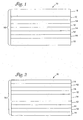
- Figures 1 and 2 illustrate multilayer optical bodies 10 (e.g., multilayer optical films) that can be used as, for example, a mirror, a polarizer, an IR film, a UV film, or a color-shifting film.
- the optical bodies 10 include one or more first optical layers 12, one or more second optical layers 14, and one or more non-optical layers 18.
- the non-optical layers 18 can be disposed on a surface of the multilayer optical body as a skin layer ( Figure 1 ) or disposed between optical layers ( Figure 2 ).
- the first and second optical layers and, optionally, the non-optical layers, if any, are coextruded and oriented by, for example, stretching. Orientation typically significantly enhances the optical power (e.g., reflectivity) of the multilayer optical bodies due to birefringence of the first or second optical layers or both.
- Such multilayer optical bodies include multilayer optical films that are suited to applications such as, for example, (i) reflective polarizers used in laptop and palmtop computer displays, cellular phone, pager, and watch displays, (ii) mirror films used in enhanced lighting, medical, and horticultural applications, (iii) color shifting films for decorative and security applications, (iv) IR reflective films used as heat management films in fields such as the automotive, horticultural, optoelectronic filtration, and architectural fields, and (v) UV reflective films used, for example, to protect other films and objects from UV radiation.
- applications such as, for example, (i) reflective polarizers used in laptop and palmtop computer displays, cellular phone, pager, and watch displays, (ii) mirror films used in enhanced lighting, medical, and horticultural applications, (iii) color shifting films for decorative and security applications, (iv) IR reflective films used as heat management films in fields such as the automotive, horticultural, optoelectronic filtration, and architectural fields, and
- the optical layers 12, 14 are typically interleaved to form a stack 16 of layers, optionally, with one or more of the non-optical layers 18 included within or as a skin layer of the stack.
- the optical layers 12, 14 are arranged as alternating pairs, as shown in Figure 1 , to form a series of interfaces between layers with different optical properties.
- the optical layers 12, 14 are typically no more than 1 ⁇ m thick and can have a thickness of 400 nm or less.
- the optical layers can have the same thicknesses.
- the multilayer optical body can include layers with different thicknesses to increase the reflective wavelength range.
- multilayer optical bodies 10 can have a large number of optical layers.
- suitable multilayer optical bodies include those having about 2 to 5000 optical layers.
- multilayer optical bodies have about 25 to 2000 optical layers and typically about 50 to 1500 optical layers or about 75 to 1000 optical layers. It will be appreciated that, although only a single stack 16 is illustrated in Figure 1 , the multilayer optical body 10 can be made from multiple stacks that are subsequently combined to form the optical body 10.
- Additional sets of optical layers similar to the first and second optical layers 12, 14, can also be used in the multilayer optical body 10.
- the design principles disclosed herein for the sets of first and second optical layers can be applied to any additional sets of optical layers.
- different repeating patterns of optical layers can be used (e.g., "ABCBA", where A, B, and C are optical layers with different compositions). Some of such patterns are set forth in U.S. Pat. No. 5,360,569 , which patterns are incorporated herein by reference.
- the transmission and reflection characteristics of the multilayer optical bodies are based on coherent interference of light caused by the refractive index difference between the first and second optical layers and the thicknesses of the first and second optical layers.
- the interface between adjacent first and second optical layers forms a reflecting surface.
- the reflective power of the interface depends on the square of the difference between the in-plane indices of refraction of the first and second optical layers (e.g., (n 10 - n 20 ) 2 , where n 10 is an in-plane refractive index of the first optical layers and n 20 is an in-plane refractive index of the second optical layers).
- the multilayer optical body typically includes first and second optical layers where both in-plane refractive indices differ substantially (e.g., differ by at least 0.04 and, often, by at least 0.1) between the layers (i.e., n 1x ⁇ n 2x and n 1y ⁇ n 2y , where n 1x and n 1y are the in-plane refractive indices of the first optical layers and n 2x and n 2y are the in-plane refractive indices of the second optical layers).
- the multilayer optical body typically includes first and second layers where one of the in-plane refractive indices differs substantially between the layers and the other in-plane refractive index is substantially similar (e.g., n 1x ⁇ n 2x and n 1y ⁇ n 2y ).
- the substantially similar in-plane refractive indices differ by no more than about 0.04.
- the in-plane birefringence of the first optical layers is typically at least about 0.05, preferably at least about 0.15, and more preferably at least about 0.2.
- the first optical layers 12 are made using birefringent polymers (preferably, polymers with positive birefringence) that are uniaxially- or, preferably, biaxially-oriented to increase the in-plane refractive index (or indices) of the first optical layers, thereby increasing the difference between the refractive indices of the first and second layers.
- the second optical layers 14 are polymer layers that are birefringent (preferably, negatively birefringent) and uniaxially- or biaxially-oriented.
- the second optical layers 14 are polymer layers having an isotropic index of refraction (e.g., substantially the same index of refraction in all directions) that is typically different from one or both of the in-plane indices of refraction of the first optical layers 12.
- an isotropic index of refraction e.g., substantially the same index of refraction in all directions
- the principles and examples described herein can be applied to multilayer optical bodies with second optical layers 14 that are birefringent.
- the first optical layers 12 can be made birefringent by, for example, stretching the first optical layers 12 in a desired direction or directions.
- the first optical layers 12 can be biaxially-oriented by stretching in two different directions.
- the stretching of optical layers 12 in the two directions can result in a net symmetrical or asymmetrical stretch in the two chosen orthogonal axes.
- Symmetrical stretching in two directions can yield in-plane refractive indices that are substantially similar (e.g., differ by no more than 0.4).
- the first optical layers 12 can be uniaxially-oriented by, for example, stretching the layers in a single direction.
- a second orthogonal direction may be allowed to neck (e.g., decrease in length, width, or thickness) into some value less than its original length.
- the direction of stretching typically corresponds to either in-plane axis (e.g. the x or y axis), however, other directions can be chosen.
- the highest reflectivity for a particular interface between first and second optical layers occurs at a wavelength corresponding to twice the combined optical thickness of the pair of optical layers 12, 14.
- the optical thickness describes the difference in path length between light rays reflected from the lower and upper surfaces of the pair of optical layers.
- the optical thickness of the two layers is n 1 d 1 +n 2 d 2 where n 1 , n 2 are the in-plane indices of refraction of the two layers and d 1 , d 2 are the thicknesses of the corresponding layers.
- the optical distance depends on the distance traveled through the layers (which is larger than the thickness of the layers) and the indices of refraction for at least two of the three optical axes of the layer.
- the optical layers 12, 14 can each be a quarter wavelength thick or the optical layers 12, 14 can have different optical thicknesses, as long as the sum of the optical thicknesses is half of a wavelength (or a multiple thereof).
- a multilayer optical body having more than two optical layers can include optical layers with different optical thicknesses to provide reflectivity over a range of wavelengths.
- a multilayer optical body can include pairs or sets of layers that are individually tuned to achieve optimal reflection of normally incident light having particular wavelengths or may include a gradient of layer pair thicknesses to reflect light over a larger bandwidth.
- These multilayer optical bodies can be designed to reflect one or both polarizations of light over at least one bandwidth.
- the layer thicknesses and indices of refraction of the optical stacks within the optical bodies can be controlled to reflect at least one polarization of specific wavelengths of light (at a particular angle of incidence) while being transparent over other wavelengths.
- the multilayer optical body of the present invention may be made to behave as mirrors or polarizers over one or more regions of the spectrum.
- the optical bodies can be designed to reflect light over substantially all of the visible light region (about 400 to 750 nm) to form a visible mirror.
- the visible mirror may be a cold mirror, reflecting only the visible wavelengths of light and transmitting the IR, or it may be a broadband mirror that reflects both the visible and IR wavelengths.
- Visible mirrors are described, for example, in U.S. Pat. No. 5,882,774 and WO 97/01774 , and a cold mirror is described, for example, inU.S. Pat. Nos. 5,339,198 and 5,552,927 , which mirrors are incorporated herein by reference.
- the typical optical layer thickness is in the range of 100 to 200 nm.
- the typical optical layer thickness is in the range of 100 to 600 nm (for a 1/4 wavelength design).
- Another embodiment is an optical body that reflects at least a portion of infrared (IR) light.
- the layers have optical thicknesses ranging from about 185-300 nm (1/4 the wavelength of the light desired to be reflected).
- the optical bodies of the present invention can be tuned to reflect both polarizations of light in at least a portion of the IR region of the spectrum while being transparent over other portions of the spectrum.
- This type of optical body can be used as an IR film to, for example, reflect solar energy from, for example, windows of buildings and automobiles.
- IR films for these uses transmit a large portion of the visible light and, more preferably, have substantially uniform transmission spectra over the visible range to avoid the appearance of color.
- Further description of IR films and examples of film configurations are presented in WO 97/01778 , WO 99/36808 , and U.S. Pat. No. 5,360,659 , which IR films and film configurations are incorporated herein by reference.
- Yet another embodiment is a multilayer optical body that reflects light over only a portion of the visible range.
- These optical bodies can be used as color shifting films, because as viewing angle changes, the wavelength region of reflection also changes. Further description of color changing films, principles of operation, and examples of film configurations are presented in WO 99/36257 and WO 99/36258 , which color changing films, principles of operation and examples of film configurations are incorporated herein by reference.
- These optical bodies can be tailored to exhibit a sharp bandedge at one or both sides of at least one reflective bandwidth, thereby giving a high degree of color saturation at acute angles, if desired, as described in WO 99/36809 , which tailoring to exhibit a sharp bandedge is incorporated herein by reference.
- the first optical layers 12 are typically orientable films of copolymers or blends of polyethylene terephthalate (PET). Examples of suitable copolymers are described in, for example, WO 99/36262 , and in co-pending U. S. Patent Application serial number 09/399,531 , which copolymers are incorporated herein by reference.
- suitable materials for the first optical layers include other polyesters, including for example, polycarbonate, polyarylate, and naphthalate and terephthalate-containing polymers, such as, for example, polybutylene naphthalate (PBN), polypropylene naphthalate (PPN), polybutylene terephthalate (PBT), and polypropylene terephthalate (PPT), and blends or copolymers of any of the above each other or with non-polyester polymers.
- PBN polybutylene naphthalate
- PPN polypropylene naphthalate
- PBT polybutylene terephthalate
- PPT polypropylene terephthalate
- Preferred properties of the material used for the first optical layers include: 1) birefringence (preferably, positive birefringence), 2) thermal stability, 3) processing temperatures compatible with the materials of the second optical layers, 4) UV stable or protectable, 5) high clarity (e.g., high transmission and low absorption), 6) a glass transition temperature that is compatible with the second optical layers to provide strain-induced birefringence, 7) a range of viscosities to permit viscosity matching with the materials of the second optical layers, 8) good interlayer adhesion with the second optical layers, 9) low dispersion, 10) good z-index matching with the second optical layers, and 11) drawability (e.g., the ability to be stretched). Other factors include cost and commercial availability.
- PEN, PET, and copolymers and blends of PEN and PET, as well as the other polymers listed above can be made birefringent by, for example, stretching the first optical layers 12 in a desired direction or directions. Orientation is typically accomplished at a temperature above the glass transition temperature of the polymer, although some copolymers with low crystallinity can be oriented at or below the glass transition temperature as described in, for example, co-pending U.S. Patent Application No. 09/399,531 .
- Polyethylene naphthalate can have a relatively large birefringence upon orientation.
- uniaxial orientation of PEN can raise the refractive index of PEN in the orientation direction from 1.64 to 1.88.
- Biaxial orientation of PEN can raise the refractive index of PEN in the orientation directions from 1.64 to 1.75, while the z index of refraction decreases to 1.49, giving a birefringence of 0.24 to 0.26 between the in-plane and z-axis refractive indices.
- Uniaxial orientation of polyethylene terephthalate can raise the refractive index of PET in the orientation direction from 1.57 to 1.69.
- Biaxial orientation of PET can raise the refractive index of PET in the orientation directions from 1.57 to 1.65, while the z index of refraction decreases to 1.50, giving a birefringence of 0.13 to 0.15 between the in-plane and z-axis refractive indices.
- the amount of birefringence and the amount of change in refractive index obtained for these polymers depend on a variety of factors including, for example, the draw ratio, the orientation temperature, and whether the polymer is uniaxially or biaxially oriented. Typically, the larger the draw ratio, the larger the change in refractive index. However, the achievable draw ratio can be limited by the orientation temperature.
- the orientation temperature is above the glass transition temperature.
- the closer that the orientation temperature is to the glass transition temperature the lower the achievable draw ratio because the polymer exhibits excessive strain hardening when drawn and can crack or form microvoids.
- the closer that the orientation temperature is to the glass transition temperature the large the change in refractive index for a given draw ratio.
- drawing the polymer at a temperature that is substantially above e.g., 20°C or 30°C
- the glass transition temperature of the polymer will typically result in significantly less change in the refractive index for a given draw ratio.
- a balance is required between draw ratio and orientation temperature to achieve a desired refractive index change.
- Polyesters like PEN and PET, include carboxylate and glycol subunits and can be generated by, for example, (a) reaction of carboxylate monomers with glycol monomers or (b) transesterification. Each carboxylate monomer has two or more carboxylic acid or ester functional groups and each glycol monomer has two or more hydroxy functional groups. Polyesters can be formed using a single type of carboxylate monomer or two or more different types of carboxylate monomers. The same applies to the glycol monomers. Also included within the term "polyester” are polycarbonates which are derived from the reaction of glycol monomers with esters of carbonic acid.
- PEN includes carboxylate subunits formed from 2,6-naphthalene dicarboxylic acid or esters thereof and PET includes carboxylate subunits formed from terephthalic acid or esters thereof.
- Suitable carboxylate comonomers for forming the carboxylate subunits of copolyesters of PEN and PET include, for example, 2,6-naphthalene dicarboxylic acid and isomers thereof; terephthalic acid; isophthalic acid; phthalic acid; azelaic acid; adipic acid; sebacic acid; norbornene dicarboxylic acid; bi-cyclooctane dicarboxylic acid; 1,6-cyclohexane dicarboxylic acid and isomers thereof; t -butyl isophthalic acid; tri-mellitic acid; sodium sulfonated isophthalic acid; 2,2'-biphenyl dicarboxylic acid and isomers thereof; and lower alkyl esters of these acids, such as methyl or ethyl esters.
- lower alkyl refers, in this context, to C1-C10 straight-chained or branched alkyl groups.
- Both PEN and PET include glycol subunits formed using ethylene glycol.
- Suitable glycol comonomers for forming glycol subunits of copolyesters of PEN and PET include propylene glycol; 1,4-butanediol and isomers thereof; 1,6-hexanediol; neopentyl glycol; polyethylene glycol; diethylene glycol; tricyclodecanediol; 1,4-cyclohexanedimethanol and isomers thereof; norbomanediol; bicyclo-octanediol; trimethylol propane; pentaerythritol; 1,4-benzenedimethanol and isomers thereof; bisphenol A; 1,8-dihydroxy biphenyl and isomers thereof; and 1,3-bis(2-hydroxyethoxy)benzene.
- Multilayer optical bodies can also be formed using polyethylene terephthalate (PET).
- PET has a lower refractive index than PEN, but PET is much less expensive (currently about one eighth the cost of PEN).
- the ratio of optical power (the square of the difference between the in-plane refractive indices of the first and second optical layers) and cost currently favors PET over PEN and other materials, such as polycarbonate.
- PET and PET-containing films can be more easily protected from ultraviolet (UV) degradation than PEN without introducing color into the UV-protected optical body.
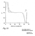
- Figure 3 illustrates the transmission spectra of PEN, PET, and polycarbonate.
- PEN absorbs light at 380 nm with an absorption tail extending into the visible region of the spectrum to about 410 nm.
- a UV protective coating or additive for an optical body made using PEN would typically extend into the visible range, which may give the optical body a yellowish color (due to absorption of blue light).
- PET absorbs light at 320 nm with a tail extending to 370 nm.
- a UV protecting coating or additive would not need to extend into the visible range. This ability is particularly important when preparing multilayer optical bodies that are designed to reflect IR light and transmit visible light (e.g., solar reflective films for building and automobile windows) or optical bodies designed to reflect only a particular bandwidth in the visible range and transmitting all other light.
- the lower refractive index and lower dispersion of PET can be advantageous in at least some respects.
- clarity or transparency of an IR film can be essential, particularly for architectural and automotive applications.
- a PET-based multilayer optical body can have less iridescence and spectral nonunformities because the optical spectrum is a weaker function of viewing angle.
- Wider IR bandwidth can also be achieved because the lower refractive index and lower dispersion in PET permits the positioning of higher order harmonics at higher wavelengths.
- PET because of its lower refractive index, will typically have lower surface reflection because of the lower refractive index mismatch between the air (or other material)/PET interface.
- PVB poly(vinyl butyrate)
- the refractive index of PVB is closer to PET than PEN, thereby reducing glare.
- Suitable PET-containing multilayer optical bodies can be formed in a variety of configurations.
- the first optical layers can be formed using a copolymer or blend of PET that is also substantially free of NDC monomer and that has a glass transition temperature of at least 100°C or at least 120°C.
- the material for the second optical layers generally will also include a material having a glass transition temperature of at least about 100°C.
- the glass transition temperature of PET can be raised by combining PET with a second polymer that has a higher glass transition temperature.
- the combination of PET and the second polymer can include miscible blending to form a polymer blend or reactive blending (by, for example, transesterification) to form a copolymer.
- PET can be blended with a second polymer that has a glass transition temperature of 130°C or higher or a second polymer with a glass transition temperature of 160°C or higher, or even a second polymer with a glass transition temperature of 200°C or higher.
- the monomer materials of PET can be copolymerized with the monomer materials that correspond to a second polymer having a higher glass transition temperature, such as PEN, polycarbonate, and polyarylate, to form copolymers.
- PET can be copolymerized with monomer materials that correspond with a second polymer that has a glass transition temperature of 130°C or higher or a second polymer with a glass transition temperature of 160°C or higher, or even a second polymer with a glass transition temperature of 200°C or higher.
- copolymers of PET can also be used, including those incorporating (i) carboxylate monomer materials, such as, for example, isophthalic acid; phthalic acid; azelaic acid; adipic acid; sebacic acid; norbomene dicarboxylic acid; bi-cyclooctane dicarboxylic acid; 1,6-cyclohexane dicarboxylic acid and isomers thereof; t-butyl isophthalic acid; tri-mellitic acid; sodium sulfonated isophthalic acid; 2,2'-biphenyl dicarboxylic acid and isomers thereof; and lower alkyl esters of these acids, such as methyl or ethyl esters; and (ii) glycol monomer materials, such as, for example, propylene glycol; 1,4-butanediol and isomers thereof; 1,6-hexanediol; neopentyl glycol; polyethylene glycol; diethylene
- the second optical layers 14 can be prepared with a variety of optical and physical properties depending, at least in part, on the desired operation of the film 10.
- Preferred properties of the second optical layers include, for example, 1) isotropic or negative birefringence, 2) thermal stability, 3) processing temperatures compatible with the materials of the first optical layers, 4) UV stable or protectable, 5) high clarity (e.g., high transmission and low absorption), 6) a glass transition temperature that is compatible with the first optical layers to provide strain-induced birefringence, 7) a range of viscosities to permit viscosity matching with the materials of the first optical layers, 8) good interlayer adhesion with the first optical layers, 9) low dispersion, 10) good z-index matching with the first optical layers, and 11) drawability (e.g., the ability to be stretched). Other factors include cost and commercial availability.
- the second optical layers 14 are made of a polymer material that does not appreciably optically orient when stretched under conditions that are used to orient the first optical layers 12. Such layers are particularly useful in the formation of reflective optical bodies, because they allow the formation of a stack 16 of layers by, for example, coextrusion, which can then be stretched to orient the first optical layers 12 while the second optical layers 14 remain relatively isotropic (e.g., an in-plane birefringence of 0.05 or less).
- the second optical layers 14 are orientable and are, preferably, negatively birefringent (when the first optical layers are positively birefringent) so that the in-plane refractive indices decrease with orientation.
- the materials of the first and second optical layers are selected so that the glass transition temperature of the second optical layers is not substantially higher than the glass transition temperature of the first optical layers. More preferably, the glass transition temperature of the second optical layers is equal to or less than the glass transition temperature of the first optical layers. If the glass transition temperature of the second optical layers is too high, orientation of the first optical layers at a suitable orientation temperature near the glass transition temperature of the first optical layers can cause excessive strain hardening in the second optical layers.
- the glass transition temperature of an optical layer is defined as the glass transition temperature of the composition that is used to form the optical layer and not the glass transition temperature(s) of the individual components.
- the difference in the z-axis refractive indices between the first and second optical layers is preferably no more than about 0.04 and, by selection of materials can be made no more than about 0.02 or no more than about 0.01.
- decomposition temperature of the polymer(s) selected for use in the second optical layers is Another consideration.
- Typical coextrusion processing temperatures for PEN and PET are above about 250°C.
- Degradation of the components of the second optical layers can produce defects in the optical body, such as, for example, discoloration and regions of gel formation. Materials that do decompose at the processing temperatures can still be used if the decomposition does not result in unacceptable properties.
- the second optical layers 14 can be made using a variety of polymeric compositions. The description of suitable polymers with respect to particular optical body configurations is provided below.
- Multilayer optical bodies have been made using PEN as the first optical layer and polymethyl methacrylate (PMMA) as the second optical layer.
- PMMA polymethyl methacrylate
- PMMA/PVDF polymethylmethacrylate/polyvinylidene fluoride blends
- the PMMA/PVDF blends are particularly useful with polyester high refractive index materials, for example aromatic polyesters such as polyethylene terephthalate (PET) and polyethylene naphthalate (PEN), as well as blends and copolymers thereof.
- PET polyethylene terephthalate
- PEN polyethylene naphthalate
- the polymers used in multilayer optical films should be clear so that light is not lost by scattering or absorption. Many applications involve multiple interactions between light and the optical film, which magnify the adverse affects of scattering and absorption.
- Optical polymers such as PMMA are considered sufficiently clear for most purposes, with transmission in the visible region of the spectrum at 92%.
- PVDF has a transmission of 96%.
- PMMA/PVDF miscible blends have higher transmission (clarity) than PMMA.
- the larger index difference results in greater optical power in the multilayer film.
- the refractive index for a PMMA/PVDF(60/40) (by weight) miscible blend is about 1.458.
- the larger index difference provided by the PMMA/PVDF blend relative to PMMA also results in a significant dampening of color leaks as well as higher reflectivity.
- Multilayer films using either PEN or PET require high coextrusion temperatures (greater than or equal to about 250 °C) due to the high melting points of these polyesters.
- Second optical layers that are not thermally stable can cause flow instabilities in the multilayer film due to viscosity loss associated with degradation. Degradation products also may result in point defects or discoloration in the optical film.
- PMMA/PVDF miscible blends are more thermally stable than PMMA.
- PMMA/PVDF miscible blends in place of PMMA in the second optical layers permits a wider variety of materials for the first optical layers because of the lower glass transition temperature (Tg) of the blends.
- Tg glass transition temperature
- PMMA/PVDF blends enable the use of PET or copolymers of PET in the first optical layers of multilayer optical bodies.
- PET has several advantages relative to PEN in multilayer optical bodies including easier UV protection and PET is a less expensive raw material.
- the orientation near the T g results in a high degree of stress birefringence and thus a high refractive index for PEN (or PET) in the direction of stretch.
- a low refractive index material for the second optical layers
- Such blends have a lower refractive index and a lower glass transition temperature as compared to PMMA, while at least maintaining suitable performance in properties such as clarity, viscosity, thermal stability and interlayer adhesion.
- the blends when coextruded with PEN or PET or blends or copolymers thereof as the high refractive index material (for the first optical layers), exhibit properties such as excellent clarity (e.g.
- the PMMA/PVDF blends can be used with conventional high refractive index materials such as PEN and achieve improved optical or physical properties.
- the use of the PMMA/PVDF blends can require fewer layers to achieve the same optical effects as a corresponding product made with PMMA in the second optical layers, or can provide enhanced effects when the same number of layers is used.
- the PMMA/PVDF blends also can be used with high refractive index materials such as PET and copolymers of PET that previously have not been found suitable for practical application in multilayer optical bodies.
- the improved optical or physical properties are advantageous in permitting less strict control over processing conditions in forming the multilayer films while still achieving the desired performance. This permits more practical and cost-effective manufacturing of the multilayer optical bodies.
- some of the advantages seen with the use of the PMMA/PVDF blends as low refractive index materials versus PMMA alone include (1) higher reflectivity - the greater difference in refractive index yields greater reflectivity for a given number of layers; (2) reduction of spectral non-uniformity or iridescence (which often results from processing difficulties such as layer non-uniformity) - again due to the larger difference in refractive index - thereby providing optical benefits and processing benefits; (3) increased efficiency in applications requiring multiple reflections; (4) wider processing tolerances such as crossweb caliper uniformity requirements and lack of optical packet overlap; (5) thinner film requirements for a given reflectivity; (6) more options for high refractive index materials; (7) improved performance in thermoforming, embossing and the like due to lower T g and (8) easier UV protection because high refractive index materials with reduced levels of PEN can be used.
- PMMA and PVDF used in the blends to provide a low refractive index material are not limited so long as the materials are sufficiently miscible with each other and the resultant blend can be coextruded with the high refractive index material to form the multilayer film.
- PMMA sold under the designations PerspexTM CP80 and CP82 by ICI Americas, Inc. (Wilmington, DE) and PVDF sold under the designation SolefTM 1008/0001 by Solway are useful with PET and PEN high refractive index materials.
- the amount of PVDF used in the blends is typically not more than about 40% by weight (i.e. a 60/40 PMMA/PVDF blend). With higher levels of PVDF, the miscibility of the PMMA and PVDF tends to deteriorate, thereby causing losses in clarity.
- smaller amounts can be used when it is desired to fine tune the composition to provide particular optical or physical properties for certain applications.
- a 75/25 blend provides highly desirable physical and optical properties for use with high refractive index materials such as PEN, PET and mixtures or copolymers thereof.
- polymethyl methacrylate is a useful material for forming the optical bodies.
- the glass transition temperature of PMMA is about 106°C, which is significantly higher than the glass transition temperature of PET (T g is about 84°C).
- An optical body with first optical layers of PET and second optical layers of PMMA would be oriented at a temperature above the glass transition temperature of PMMA, significantly reducing the refractive index change expected for orientation of PET.
- the blending of polyvinylidene fluoride (PVDF) with PMMA reduces the glass transition temperature of the blended polymers.
- the blend includes about 20 to 40 wt.% PVDF and 60 to 80 wt.% PMMA. Below about 20 wt.% PVDF, the glass transition temperature is above that of PET, although these blends are still acceptable for some applications. Above about 40 wt.%, PVDF crystallizes.
- the addition of PVDF to the second optical layers can also enhance other properties, such as, for example, solvent resistance.
- copolymers of PMMA can be made using comonomers that depress the glass transition temperature of the copolymer below the glass transition temperature of PMMA.
- Suitable comonomers include other acrylate and methacrylate monomers including, for example, ethyl acrylate, butyl acrylate, n-butyl methacrylate, ethyl methacrylate, methacrylic acid, or combinations thereof.
- Other acrylate monomers can be used so long as the desired glass transition temperature, thermal stability, drawability, and refractive index properties are achieved. The ratio of monomers are selected to achieve the desired glass transition temperature, thermal stability, drawability, and refractive index properties.
- the comonomers can also provide other advantages including, for example, improved interlayer adhesion, increasing or decreasing the refractive index difference between the first and second layers, modifying the melt rheology behavior of the PMMA, or modifying the orientation behavior of the PMMA.
- second optical layers can be formed using PMMA and a plasticizer that decreases the glass transition temperature of the second optical layers.
- suitable plasticizers include, for example, phosphoric acid derivatives (e.g., triphenyl phosphate), phthalic acid derivatives (e.g., butyl benzyl phthalate and diisodecyl phthalate), terephthalic acid derivatives (e.g., di-2-ethylhexyl terephthalate), adipic acid derivatives (e.g., polyester adipate), benzoic acid derivatives (e.g., glyceryl tribenzoate), sebacic acid derivatives (e.g., dimethyl sebacate and di-n-butyl sebacate), and acetic acid derivatives (e.g., glyceryl triacetate).
- phosphoric acid derivatives e.g., triphenyl phosphate
- phthalic acid derivatives e.g., butyl benz
- a plasticizer can also be selected that improves other properties of the optical body including, for example, interlayer adhesion, increasing or decreasing the refractive index difference between the first and second layers, modifying the melt rheology behavior of the PMMA, or modifying the orientation behavior of the PMMA.
- aliphatic polyolefins can be used.
- suitable polyolefins include poly(ethylene-co-octene) (PE-PO), poly(propylene-co-ethylene) (PP-PE), a copolymer of atactic and isotactic polypropylene (aPP-iPP), maleic anhydride functionalized linear low density polyethylene (LLDPE-g-MA), and poly(ethylene-co-vinyl acetate) (EVA).
- PE-PO poly(ethylene-co-octene)
- PP-PE poly(propylene-co-ethylene)
- aPP-iPP copolymer of atactic and isotactic polypropylene
- LLDPE-g-MA maleic anhydride functionalized linear low density polyethylene
- EVA poly(ethylene-co-vinyl acetate)
- Other useful polyolefins include acid-modified polyolefins such as "Bynel" polyolefins from E.
- polyolefins typically do not substantially degrade at the processing temperatures utilized with PEN and PET.
- elastomeric polyolefins can enhance mechanical properties of the multilayer optical bodies, including, for example, tear resistance, puncture resistance, and toughness.
- one or more of the non-optical layers 18 can be formed as a skin layer or skin layers over at least one surface of stack 16 as illustrated in Figure 1 , to, for example, protect the optical layers 12, 14 from physical damage during processing and/or afterwards.
- one or more of the non-optical layers 18 can be formed within the stack 16 of layers, as illustrated in Figure 2 , to, for example, provide greater mechanical strength to the stack or to protect the stack during processing.
- the non-optical layers 18 ideally do not significantly participate in the determination of optical properties of the multilayer optical film 10, at least across the wavelength region of interest (e.g., visible, IR or UV wavelength regions).
- the non-optical layers 18 may or may not be birefringent or orientable.
- the non-optical layers 18 are used as skin layers there will be at least some surface reflection.
- the non-optical layers preferably have an index of refraction that is relatively low (e.g., no more than 1.6 or, preferably, no more than 1.5) to decrease the amount of surface reflection (e.g., iridescence).
- the non-optical layers preferably have a relatively high refractive index (e.g., at least 1.6, more preferably at least 1.7) to increase reflectance of the multilayer optical body.
- the non-optical layers 18 When the non-optical layers 18 are found within the stack 16, there will typically be at least some polarization or reflection of light by the non-optical layers 18 in combination with the optical layers 12, 14 adjacent to the non-optical layers 18. In at least some instances, however, the non-optical layers 18 can be selected to have a thickness that dictates that light reflected by the non-optical layers 18 within the stack 16 has a wavelength outside the region of interest, for example, in the infrared region for optical bodies that reflect visible light. The thickness of the non-optical layers 18 can be at least two times, typically at least four times, and, in many instances, at least ten times, the thickness of one of the individual optical layers 12, 14.
- the thickness of the non-optical layers 18 can be varied to make an optical body 10 having a particular thickness.
- one or more of the non-optical layers 18 are placed so that at least a portion of the light to be transmitted, polarized, and/or reflected by the optical layers 12, 14, also travels through the non-optical layers (i.e., the non-optical layers are placed in the path of light which travels through or is reflected by the optical layers 12, 14).
- the non-optical layers 18 are formed from polymers including any of the polymer used in the first and second optical layers.
- the material selected for the non-optical layers 18 is similar to or the same as the material selected for the second optical layers 14. Materials may be chosen for the non-optical layers that impart or improve properties such as, for example, tear resistance, puncture resistance, toughness, weatherability, and solvent resistance of the multilayer optical body.
- Various functional layers or coatings can be added to the multilayer optical bodies of the present invention to alter or improve their physical or chemical properties, particularly along the surface of the multilayer optical body.
- Such layers or coatings may include, for example, slip agents, low adhesion backside materials, conductive layers, antistatic coatings or films, barrier layers, flame retardants, UV stabilizers, abrasion resistant materials, optical coatings, and/or substrates designed to improve the mechanical integrity or strength of the film or device, as described in WO 97/01440 , which layers or coatings are incorporated by reference.
- Dichroic polarizing films can also be coated on or co-extruded with the multilayer optical films, as described, for example, in WO 95/17691 , WO 99/36813 , and WO 99/36814 , which coating or co-extruding is incorporated by reference.
- An initial step in the manufacture of the multilayer optical bodies is the generation of the polymers to be used in formation of the first and second optical layers, as well as the non-optical layers (unless the polymers are available commercially).
- these polymers are formed by extrusion, although other methods of polymer formation can be used. Extrusion conditions are chosen to adequately feed, melt, mix and pump the polymer resin feed streams in a continuous and stable manner. Final melt stream temperatures are chosen to be within a range that reduces freezing, crystallization, or unduly high pressure drops at the low end of the range and that reduces degradation at the high end of the range.
- the entire melt stream processing of more than one polymer, up to and including film casting on a chill roll, is often referred to as co-extrusion.
- the polymers of the first optical layers, the second optical layers, and the non-optical layers are chosen to have similar rheological properties (e.g., melt viscosities) so that they can be co-extruded.
- the second optical layers and the non-optical layers have a glass transition temperature, T g , that is either below or no greater than about 30°C above the glass transition temperature of the first optical layers.
- T g glass transition temperature
- the glass transition temperature of the second optical layers and the non-optical layers is below the glass transition temperature of the first optical layers.
- each melt stream is conveyed to a gear pump used to regulate the continuous and uniform rate of polymer flow.
- a static mixing unit can be used to carry the polymer melt stream from the gear pump into a multilayer feedblock with uniform melt stream temperature.
- the entire melt stream is typically heated as uniformly as possible to enhance both uniform flow of the melt stream and reduce degradation during melt processing.
- Multilayer feedblocks divide each of the two or more polymer melt streams into many layers, interleave these layers, and combine the many layers into a single multilayer stream.
- the layers from any given melt stream are created by sequentially bleeding off part of the stream from a main flow channel into side channel tubes which lead to layer slots in the feed block manifold.
- the layer flow can be controlled by choices made in machinery, as well as the shape and physical dimensions of the individual side channel tubes and layer slots.
- the side channel tubes and layer slots of the two or more melt streams are often interleaved to form alternating layers.
- the feedblock's downstream-side manifold is typically shaped to compress and uniformly spread the layers of the combined multilayer stack transversely.
- Thick, non-optical layers known as protective boundary layers (PBLs)
- PBLs protective boundary layers
- these non-optical layers can be used to protect the thinner optical layers from the effects of wall stress and possible resulting flow instabilities.
- the multilayer stack exiting the feedblock manifold enters a final shaping unit such as a die.
- the stream can be split, preferably normal to the layers in the stack, to form two or more multilayer streams that can be recombined by stacking.
- the stream can also be split at an angle other than normal to the layers.
- a flow channeling system that splits and stacks the streams is called a multiplier.
- the width of the split streams i.e., the sum of the thicknesses of the individual layers
- the multiplier ratio is defined as the ratio of the wider to narrower stream widths.
- Unequal streams widths i.e., multiplier ratios greater than unity
- the multiplier may spread the narrower stream and/or compress the wider stream transversely to the thickness and flow directions to ensure matching layer widths upon stacking.
- non-optical layers Prior to multiplication, additional non-optical layers can be added to the multilayer stack. These non-optical layers may perform as PBLs within the multiplier. After multiplication and stacking, some of these layers can form internal boundary layers between optical layers, while others form skin layers.
- the web is directed to a final shaping unit.
- the web is then cast onto a chill roll, sometimes also referred to as a casting wheel or casting drum.
- This casting is often assisted by electrostatic pinning, the details of which are well-known in the art of polymer film manufacture.
- the web can be cast to a uniform thickness across the web or a deliberate profiling of the web thickness can be induced using die lip controls.
- the multilayer web is then uniaxially or biaxially drawn to produce the final multilayer optical film.
- Uniaxial drawing is performed in a tenter or a length orienter.
- Biaxial drawing typically includes both types of equipment. Typical tenters draw in a transverse direction (TD) to the web path, although certain tenters are equipped with mechanisms to draw or relax (shrink) the film dimensionally in the web path or machine direction (MD). Length orienters draw in the machine direction.
- TD transverse direction
- MD machine direction
- Length orienters draw in the machine direction.
- a two step drawing process is used to orient the birefringent material in both in-plane directions.
- the draw processes can be any combination of the single step processes described above that allow drawing in two in-plane directions.
- a tenter that allows drawing along the machine direction, e.g. a biaxial tenter which can draw in two directions sequentially or simultaneously, can be used. In this latter case, a single biaxial draw process can be used.
- Monomers, catalysts, and stabilizers utilized in creating polymers for these examples are commercially available from the following suppliers: dimethyl naphthalene dicarboxylate from Amoco (Decatur, Alabama), dimethyl terephthalate from Hoechst Celanese (Dallas, TX), ethylene glycol from Union Carbide (Charleston, WV), 1,6-hexanediol from BASF (Charlotte, NC), antimony triacetate from Elf Atochem (Philadelphia, PA), manganese acetate and triethyl phosphonoacetate, both from Albright & Wilson (Glen Allen, VA).
- the polyethylene terephthalate used in the following Examples can be synthesized in a batch reactor with the following raw material charge: 5,000 kg dimethyl terephthalate, 3,502 kg ethylene glycol, 1.2 kg manganese acetate, and 1.6 kg antimony triacetate. Under pressure of 202.6 kPa (1520 torr), this mixture is heated to 254 °C while removing the transesterification reaction by-product methanol. After 1,649 kg of methanol was removed, 2.45 kg of triethyl phosphonoacetate is charged to the reactor and than the pressure is gradually reduced to 133 Pa (1 torr) while heating to 280 °C. The condensation reaction by-product, ethylene glycol, is continuously removed until a polymer with an Intrinsic Viscosity of 0.60, as measured in 60/40 phenol/dichlorobenzene, is produced.
- An optical film was constructed with first optical layers created from polyethylene terephthalate (PET) and second optical layers created from a copolymer using 75 wt.% methylmethacrylate (MMA) monomers and 25 wt.% of ethyl acrylate (EA) monomers.
- PET polyethylene terephthalate
- EA ethyl acrylate
- the copolymer is available under the product designation "Perspex TM CP63" from ICI Americas, Inc. (Wilmington, DE).
- the above described polymers were then coextruded through a multilayer melt manifold to create a multilayer film with 224 alternating first and second Optical layers of a total thickness of about 580 ⁇ m.
- This particular multilayer reflective film also contained external protective layers made of the same polyethylene terephthalate as the first, optical layers approximately 145 ⁇ m thick on each side.
- the optical film was initially preheated, then stretched in the machine direction to a ratio of 3.7:1 at approximately 85 °C, and then stretched in the transverse direction to a ratio of 3.9:1 at approximately 95°C to produce an optical film of approximately 48 ⁇ m thickness.
- the second optical layers were essentially isotropic with a refractive index of about 1.49.
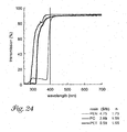
- the optical film had the transmission spectrum illustrated in Figure 4 for normally incident light.
- the optical film had a blue appearance that changed to red as the viewing angle increased with respect to normal incidence.
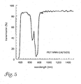
- This optical film was made in the same way as the optical film of Example 1, except that during the drawing process, the optical film was initially preheated to 94°C for 1 minute, then biaxially stretched at a 3.4:3.4 ratio at 94°C at a draw rate of 20%/s.
- the second optical layers were essentially isotropic with, a refractive index of about 1.49.
- the optical film had the transmission spectrum illustrated in Figure 5 for normally incident light.
- the optical film had a blue appearance that changed to red as the viewing angle increased with respect to normal incidence.
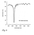
- This optical film was made in the same way as the optical film of Example 1, except that during the drawing process, the optical film was initially preheated to 84°C for 1 minute, then biaxially stretched at a 2.4:2.4 ratio at 84°C at a draw rate of 20%/s.
- the second optical layers were essentially isotropic with a refractive index of about 1.49.
- the optical film had the transmission spectrum illustrated in Figure 6 for normally incident light.
- the optical film had a red appearance that changed to yellow as the viewing angle increased with respect to normal incidence.
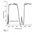
- This optical film was made in the same way as the optical film of Example 1, except that the total thickness of the cast film was 625 ⁇ m and during the drawing process, the optical film was initially preheated, then biaxially stretched at a 3.6:3.8 ratio at approximately 100 °C. The final film thickness was about 51 ⁇ m.
- the second optical layers were essentially isotropic with a refractive index of about 1.49.
- the optical film had the transmission spectrum illustrated in Figure 7 for normally incident light.
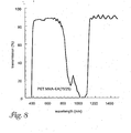
- This optical film was made in the same way as the optical film of Example 1, except that the total thickness of the cast film was 625 ⁇ m and during the drawing process, the optical film was initially preheated, then stretched in the machine direction to a ratio of 3.6:1 at approximately 100 °C, and then stretched in the transverse direction to a ratio of 3.8:1 at approximately 100 °C. The final film thickness was about 48.8 ⁇ m.
- the second optical layers were essentially isotropic with a refractive index of about 1.49.
- the optical film had the transmission spectrum illustrated in Figure 8 for normally incident light.
- This optical film was made in the same way as the optical film of Example 1, except that only 150 alternating layers were used, and during the drawing process the optical film was initially preheated to 94°C for 1 minute, then stretched draw ratio of 3.6:3.2 at 94°C at a draw rate of 20 %/s. The final film thickness was about 29.5 ⁇ m.
- the second optical layers were essentially isotropic with a refractive index of about 1.49.
- the optical film had the transmission spectrum illustrated in Figure 9 for normally incident light.
- Optical films can be formed using first optical layers created from PET and second optical layers created from a PMMA copolymer.
- the PMMA copolymer is formed with MMA comonomer units and n- butyl methacrylate (nBMA) comonomer units.
- nBMA n- butyl methacrylate
- Optical films can be formed using first optical layers created from PET and second optical layers created from a PMMA copolymer.
- the PMMA copolymer is formed with MMA comonomer units, n-butyl methacrylate (nBMA) comonomer units, and ethyl acrylate (EA) comonomer units.
- nBMA and EA comonomer units depress the T g of the PMMA copolymer below the T g of PMMA.
- EA comonomer units can also increase the thermal stability of the films.
- Optical films can be formed using first optical layers created from PET and second optical layers created from polyethyl methacrylate (PEMA).
- PEMA has a lower glass transition temperature (67 °C) than PMMA (106°C).
- Optical films can be formed using first optical layers created from PET and second optical layers created from a PEMA copolymer.
- the PEMA copolymer is formed with ethyl methacrylate (EMA) comonomer units and butyl acrylate (BA) comonomer units.
- EMA ethyl methacrylate
- BA butyl acrylate
- the butyl acrylate comonomer units have a higher allowable odor threshold than ethyl methacryalate and so can be used to make a more acceptable polymer layer.
- Optical films can be formed using first optical layers created from PET and second optical layers created from a PMMA copolymer.
- the PMMA copolymer is formed with MMA comonomer units, ethyl acrylate (EA) comonomer units, and methacrylic acid (MA) comonomer units.
- EA ethyl acrylate
- MA methacrylic acid
- the EA comonomer units depress the T g of the PMMA copolymer below the T g of PMMA.
- EA comonomer units can also increase the thermal stability of the film.
- MA comonomer units are used to increase interlayer adhesion with the PET first optical layers.
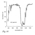
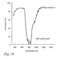
- Optical films can be formed using first optical layers created from PET and second optical layers created from a blend of PMMA and poly(vinylidene fluoride) (PVDF) (e.g., Solef TM 1008 available from Solvay Polymers, Inc. (Houston, TX)) in a ratio of 75/25 by weight.
- PVDF poly(vinylidene fluoride)
- the PMMA/PVDF blend as a lower T g (72°C) and refractive index (1.47) than PMMA.
- the refractive index difference between the first and second optical layers is about 0.18.
- PVDF also provides other benefits including improved solvent resistance and weatherability.
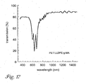
- Optical films can be formed using first optical layers created from PET and second optical layers created from a blend of PMMA and poly(vinylidene fluoride) (PVDF) (e.g., Solef TM 1008 available from Solvay Polymers, Inc. (Houston, TX)) in a ratio of 60/40 by weight.
- PVDF poly(vinylidene fluoride)
- the PMMA/PVDF blend as a lower T g (66°C) and refractive index (1.458) than PMMA.
- the refractive index difference between the first and second optical layers is about 0.19.
- PVDF also provides other benefits including improved solvent resistance and weatherability.
- IR Film with PET:PMMA/PVDF 75/25) Layers.
- An optical film was constructed with first optical layers created from a polyethylene terephthalate (PET) and second optical layers created from a blend using 75 wt.% PMMA (Perspx TM CP82, ICI Americas, Inc. (Wilmington, DE)) and 25 wt.% polyvinylidene fluoride (PVDF) (Solef TM 1008, Solvay Polymers, Inc. (Houston, TX)).
- PET polyethylene terephthalate
- PVDF polyvinylidene fluoride
- the above described polymers were then coextruded through a multilayer melt manifold to create a multilayer film with 196 alternating first and second optical layers.
- This particular multilayer reflective firm also contained external protective layers made of the same polyethylene terephthalate as the first optical layers.
- the optical film was initially preheated; then stretched to a ratio of between 3.6 and 3.8 in each of the machine and transverse directions at approximately 100 °C to produce an optical film of approximately 40.4 ⁇ m thick.
- the optical film had the transmission spectrum illustrated in Figure 10 for normally incident light.
- PET polyethylene terephthalate
- PET polyethylene terephthalate
- PE-PO polyolefin copolymer poly(ethylene-co-octene)
- the above described polymers were then coextruded through a multilayer melt manifold to create a multilayer film with 224 alternating first and second optical layers.
- the cast film had a total thickness of about 533 ⁇ m.
- This particular multilayer reflective film also contained external protective layers made of the same polyethylene terephthalate as the first optical layers.
- the optical film was initially preheated, then stretched in the machine direction to a ratio of 3.8:1 at approximately 100°C, and then stretched in the transverse direction to a ratio of 3.6:1 approximately 100°C to produce an optical film of approximately 38.6 ⁇ m.
- the second optical layers were essentially isotropic with a refractive index of about 1.49.
- the optical film had the transmission spectrum illustrated in Figure 11 for normally incident light.
- the optical film had a blue appearance that changed to red as the viewing angle increased with respect to normal incidence.
- IR Film with PET:PE-PO Layers An optical film was constructed with first optical layers created from a polyethylene terephthalate (PET) and second optical layers created from a polyolefin copolymer poly(ethylene-co-octene) (PE-PO).
- PET polyethylene terephthalate
- PE-PO polyolefin copolymer poly(ethylene-co-octene)
- the copolymer is available under the product designation "Engage 8200" from Dow-DuPont Elastomers.
- the above described polymers were then coextruded through a multilayer melt manifold to create a multilayer film with 224 alternating first and second optical layers.
- the cast film had a total thickness of about 533 ⁇ m.
- This particular multilayer reflective film also contained external protective layers made of the same polyethylene terephthalate as the first optical layers.
- the optical film was initially preheated, then stretched in the machine direction to a ratio of 3.6:1 at approximately 100 °C, and then stretched in the transverse direction to a ratio of 3.8:1 approximately 100°C to produce an optical film of approximately 57.1 ⁇ m.
- the second optical layers were essentially isotropic with a refractive index of about 1.49.
- the optical film had the transmission spectrum illustrated in Figure 12 for normally incident light.
- the optical film had a clear appearance with a slight yellow observed at higher viewing angles.
- Color-shifting Optical Film with PET PP-PE Layers.
- An optical film was constructed with first optical layers created from a polyethylene terephthalate (PET) and second optical layers created from a polyolefin copolymer poly(propylene-co-ethylene) (PP-PE).
- the copolymer is available under the product designation "Z9470” from Fina Oil and Chemical Co., Dallas, TX.
- the above described polymers were then coextruded through a multilayer melt manifold to create a multilayer film with 224 alternating first and second optical layers.
- the cast film had a total thickness of about 719 ⁇ m.
- This particular multilayer reflective film also contained external protective layers made of the same polyethylene terephthalate as the first optical layers.
- the cast film was heated in an oven charged with hot air set at 94°C and then oriented at a 4.4:4.4 draw at a draw temperature of 94°C and a draw rate of 20%/s.
- the second optical layers were essentially isotropic with a refractive index of about 1.49.
- the optical film had the transmission spectrum illustrated in Figure 13 for normally incident light.
- the optical film had a blue appearance that changed to red as the viewing angle increased with respect to normal incidence.
- IR Film with PET PP-PE Layers.
- An optical film was constructed with first optical layers created from a polyethylene terephthalate (PET) and second optical layers created from a polyolefin copolymer poly(propylene-co-ethylene) (PP-PE).
- the copolymer is available under the product designation "Z9470” from Fina Oil and Chemical Co., Dallas, TX.
- the above described polymers were then coextruded through a multilayer melt manifold to create a multilayer film with 224 alternating first and second optical layers.
- the cast film had a total thickness of about 719 ⁇ m.
- This particular multilayer reflective film also contained external protective layers made of the same polyethylene terephthalate as the first optical layers.
- the optical film was initially preheated, then stretched in the machine direction to a ratio of 3.6:1 at approximately 100°C, and then stretched in the transverse direction to a ratio of 3.8:1 approximately 100 °C to produce an optical film of approximately 42.4 ⁇ m.
- the second optical layers were essentially isotropic with a refractive index of about 1.49.
- the optical film had the transmission spectrum illustrated in Figure 14 for normally incident light.
- the optical film had a slight yellow appearance at normal incidence, but became clear as viewing angle increased.
- Color-shifting Optical Film with PET:aPP-iPP Layers An optical film was constructed with first optical layers created from a polyethylene terephthalate (PET) and second optical layers created from a polyolefin copolymer of atactic polypropylene (aPP) and isotactic polypropylene (iPP).
- PET polyethylene terephthalate
- iPP isotactic polypropylene
- the copolymer is available under the product designation "Rexflex W111" from Huntsman Chemical Corp., Salt Lake City, UT.
- the above described polymers were then coextruded through a multilayer melt manifold to create a multilayer film with 224 alternating first and second optical layers.
- the cast film had a total thickness of about 683 ⁇ m.
- This particular multilayer reflective film also contained external protective layers made of the same polyethylene terephthalate as the first optical layers.
- the cast film was heated in an oven charged with hot air set at 94°C and then oriented at a 3.5:3.5 draw at a draw temperature of 94°C and a draw rate of 20%/s to produce an optical film of approximately 34 ⁇ m.
- the second optical layers were essentially isotropic with a refractive index of about 1.49.
- the optical film had the transmission spectrum illustrated in Figure 15 for normally incident light.
- the optical film had a blue appearance that changed to red as the viewing angle increased with respect to normal incidence.
- IR Film with PET:aPP-iPP Layers An optical film was constructed with first optical layers created from a polyethylene terephthalate (PET) and second optical layers created from a polyolefin copolymer of atactic polypropylene (aPP) and isotactic polypropylene (iPP).
- PET polyethylene terephthalate
- iPP isotactic polypropylene
- the copolymer is available under the product designation "Rexflex W111" from Huntsman Chemical Corp., Salt Lake City, UT.
- the above described polymers were then coextruded through a multilayer melt manifold to create a multilayer film with 224 alternating first and second optical layers.
- the cast film had a total thickness of about 683 ⁇ m.
- This particular multilayer reflective film also contained external protective layers made of the same polyethylene terephthalate as the first optical layers.
- the cast film was heated in an oven charged with hot air set at 94°C and then oriented at a 2.8:2.8 draw at a draw temperature of 94°C and a draw rate of 20%/s to produce an optical firm.
- the second optical layers were essentially isotropic with a refractive index of about 1.49.
- the optical film had the transmission spectrum illustrated in Figure 16 for normally incident light.
- the optical film had a slight red tint at normal incidence, but became clear as viewing angle increased.
- Color-shifting Optical Film with PET:LLDPE-g-MA Layers An optical film was constructed with first optical layers created from a polyethylene terephthalate (PET) and second optical layers created from a functionalized polyolefin, linear low density polyethylefie-g-maleic anhydride (LLDPE-g-MA).
- PET polyethylene terephthalate
- LLDPE-g-MA linear low density polyethylefie-g-maleic anhydride
- the copolymer is available under the product designation "Bynel 4105" from E.I. duPont de Nemours & Co., Inc. (Wilmington, DE).
- the above described polymers were then coextruded through a multilayer melt manifold to create a multilayer film with 224 alternating first and second optical layers.
- This particular multilayer reflective film also contained external protective layers made of the same polyethylene terephthalate as the first optical layers.
- the cast film was heated in an oven charged with hot air set at 94°C and then oriented at a 3.5:3.7 draw at a draw temperature of 94°C and a draw rate of 20%/s to produce an optical film of approximately 33.8 ⁇ m.
- the second optical layers were essentially isotropic with a refractive index of about 1.49.
- the optical film had the transmission spectrum illustrated in Figure 17 for normally incident light.
- IR Film with PET:LLDPE-g-MA Layers An optical film was constructed with first optical layers created from a polyethylene terephthalate (PET) and second optical layers created from a functionalized polyolefin, linear low density polyethylene-g-maleic anhydride (LLDPE-g-MA).
- PET polyethylene terephthalate
- LLDPE-g-MA linear low density polyethylene-g-maleic anhydride
- the copolymer is available under the product designation "Bynel 4105" from E.I. duPont de Nemours & Co., Inc. (Wilmington, DE).
- the above described polymers were then coextruded through a multilayer melt manifold to create a multilayer film with 224 alternating first and second optical layers.
- This particular multilayer reflective film also contained external protective layers made of the same polyethylene terephthalate as the first optical layers.
- the optical film was initially preheated, then stretched in the machine direction to a ratio of 3.6:1 at approximately 100 °C, and then stretched in the transverse direction to a ratio of 3.8:1 approximately 100 °C to produce an optical film of approximately 40.9 ⁇ m.
- the second optical layers were essentially isotropic with a refractive index of about 1.49.
- the optical film had the transmission spectrum illustrated in Figure 18 for normally incident light.
- the optical film was clear at normal incidence, but became slightly blue as viewing angle increased.
- Oriented optical films can be formed using first optical layers created from PET and second optical layers created from poly(ethylene-co-vinyl acetate) (EVA).
- EVA poly(ethylene-co-vinyl acetate)
- Oriented optical films can be formed using first optical layers created from PET and second optical layers created a miscible blend of poly(ethylene-co-vinyl acetate) and poly(ethylene-co-propylene).
- Oriented optical films can be formed using first optical layers created from copolymerization or reactive blending of PET and polycarbonate (PC) and second optical layers created from polymethyl methacrylate (PMMA).
- Polycarbonate has a glass transition temperature of 157°C.
- Oriented optical films can be formed using first optical layers created from copolymerization or reactive blending of PET and polyarylate (PAr) and second optical layers created from polymethyl methacrylate (PMMA).
- Polyarylate has a glass transition temperature of 193°C.
- Oriented optical films can be formed using first optical layers created from miscible blending of PET and polyetherimide (PEI) and second optical layers created from polymethyl methacrylate (PMMA).
- PEI polyetherimide
- PMMA polymethyl methacrylate
- Polyetherimide has a glass transition temperature of 218°C.
- Oriented optical films can be formed using first optical layers created from copolymerization or reactive blending of 90 wt.% PET and 10 wt.% PEN and second optical layers created from poly(ethylene-co-vinyl acetate) (EVA).
- Oriented optical films can be formed using first optical layers created from copolymerization or reactive blending of 30 wt.% PET and 70 wt.% PEN and second optical layers created from poly(ethylene-co-vinyl acetate) (EVA).
- a multilayer cast film was coextruded containing about 450 layers of alternating PEN (0.48 intrinsic viscosity from Eastman Chemical Products, Inc., Kingsport, TN) and a miscible PMMA/PVDF(60/40, by weight) blend.
- PMMA was Perspex TM CP80 from ICI Americas, Inc. (Wilmington, DE) and PVDF was Solef TM 1008 from Solvay Polymers, Inc. (Houston, TX).
- the extruded cast film was subsequently and continuously biaxally-oriented.
- the sequential biaxial orientation process involved a first orientation step in the machine direction (MD) in a length orienter followed by a transverse direction (TD) orientation, in a tenter.
- the finished optical film had an overall thickness of approximately 58.4 ⁇ m.
- a PEN:PMMA multilayer mirror film was processed with the same equipment and under similar conditions.
- the reflectivity of Figure 1 is a photopical average from measured transmission spectra (CIE Illuminant C, 2° observer).
- Figure 20 shows the reflectivity of the PEN:PMMA and PEN:PMMMPVDF(60M0) films as a function of wavelength.
- the PEN:PMMA film shows a relatively nonuniform spectrum with a significant degree of "spikes" which lead to undesirable spectral nonuniformity (iridescence).
- the spectral nonuniformity (iridescence) is associated with processing difficulties including layer thickness variations and lack of optical packet overlap.
- the higher refractive index difference of the PEN:PMMA/PVDF(60/40) multilayer mirror film results in a significant dampening of the spectral nonuniformity (iridescence).
- the demonstrated reduction in spectral nonuniformity (iridescence) in the PEN:PMMA/PVDF(60/40) film relative to the PEN:PMMA film represents both an optical and processing benefit.
- Figure 21 shows the same reduction in spectral nonuniformity (iridescence) with PEN:PMMAlPVDF(60/40) relative to PEN:PMMA for films of similar bandwidths.
- Figures 22 and 23 show a comparison of color index parameters as a function of crossweb distance for he PEN:PMMA and PEN:PMMAMVDF(60M0) films.
- the color index parameters were photopically averaged from measured transmission spectra (CIE Illuminant C, 2° observer). Ideally the color index parameters are zero.
- the figures show PEN:PMMA/PVDF(60/40) film shows better color performance relative to the PEN:PMMA film over a majority of the film width.
- Multilayer Optical Film with coPEN(70130):PMMA/PVDF(60/40) Layers A multilayer optical film similar to that of Example 3 0 was formed except that a copolymer of PEN with carboxylate subunits formed using 70wt.% naphthalate monomers and 30wt.% terephthalate monomers was used.
- the lower PEN contend provides a film with a UV absorption band edge further from the visible region of the spectrum allowing easier UV protection of the film.
- the lower glass transition temperature of the coPEN (110°C) relative to PEN (124°C) may also have benefits in thermoforming, embossing, and the like.
Claims (4)
- Corps optique comprenant :une pluralité de premières couches optiques, chaque première couche optique étant orientée et comprenant une première composition polymère, la première composition polymère comprenant(i) une partie polyester comportant des motifs comonomères de téréphtalate et des motifs comonomères d'éthylène glycol, et(ii) une deuxième partie correspondant à un polymère ayant une température de transition vitreuse d'au moins 130 °C,dans lequel
la partie polyester et la deuxième partie sont formées par copolymérisation de monomères, ou
la première composition polymère est formée par mélange réactif de téréphtalate de polyéthylène et d'un deuxième polymère ayant une température de transition vitreuse d'au moins 130 °C pour former la partie polyester et la deuxième partie, respectivement, ou
la première composition polymère est formée par mélange miscible de téréphtalate de polyéthylène et d'un deuxième polymère ayant une température de transition vitreuse d'au moins 130 °C pour former un mélange polymère, et
dans lequel la température de transition vitreuse des premières couches optiques est d'au moins 100 °C ; etune pluralité de deuxièmes couches optiques disposées en une séquence répétitive avec la pluralité de premières couches optiques, chaque deuxième couche optique comprenant une deuxième composition polymère,
dans lequel ladite deuxième composition polymère comprend du polyméthacrylate de méthyle,
le corps optique réfléchissant la lumière sur une certaine gamme de longueurs d'onde. - Corps optique selon la revendication 1, dans lequel la deuxième partie correspond à un polymère ayant une température de transition vitreuse d'au moins 160 °C.
- Corps optique selon la revendication 1, dans lequel la deuxième partie correspond à un polymère ayant une température de transition vitreuse d'au moins 200 °C.
- Corps optique selon la revendication 1, dans lequel la température de transition vitreuse des premières couches optiques est d'au moins 120 °C.
Priority Applications (1)
| Application Number | Priority Date | Filing Date | Title |
|---|---|---|---|
| EP09173276A EP2149801A1 (fr) | 1999-11-22 | 1999-12-29 | Film biréfringent polymérique multicouches avec une couche épaisse non-optique |
Applications Claiming Priority (3)
| Application Number | Priority Date | Filing Date | Title |
|---|---|---|---|
| US09/444,756 US6498683B2 (en) | 1999-11-22 | 1999-11-22 | Multilayer optical bodies |
| US444756 | 1999-11-22 | ||
| EP99972444A EP1232405B1 (fr) | 1999-11-22 | 1999-12-29 | Corps optiques multicouches |
Related Parent Applications (2)
| Application Number | Title | Priority Date | Filing Date |
|---|---|---|---|
| EP99972444A Division EP1232405B1 (fr) | 1999-11-22 | 1999-12-29 | Corps optiques multicouches |
| EP99972444.6 Division | 1999-12-29 |
Related Child Applications (1)
| Application Number | Title | Priority Date | Filing Date |
|---|---|---|---|
| EP09173276.8 Division-Into | 2009-10-16 |
Publications (3)
| Publication Number | Publication Date |
|---|---|
| EP1491920A2 EP1491920A2 (fr) | 2004-12-29 |
| EP1491920A3 EP1491920A3 (fr) | 2005-01-19 |
| EP1491920B1 true EP1491920B1 (fr) | 2010-06-09 |
Family
ID=23766221
Family Applications (3)
| Application Number | Title | Priority Date | Filing Date |
|---|---|---|---|
| EP99972444A Expired - Lifetime EP1232405B1 (fr) | 1999-11-22 | 1999-12-29 | Corps optiques multicouches |
| EP09173276A Withdrawn EP2149801A1 (fr) | 1999-11-22 | 1999-12-29 | Film biréfringent polymérique multicouches avec une couche épaisse non-optique |
| EP04021443A Expired - Lifetime EP1491920B1 (fr) | 1999-11-22 | 1999-12-29 | Corps optiques multicouches |
Family Applications Before (2)
| Application Number | Title | Priority Date | Filing Date |
|---|---|---|---|
| EP99972444A Expired - Lifetime EP1232405B1 (fr) | 1999-11-22 | 1999-12-29 | Corps optiques multicouches |
| EP09173276A Withdrawn EP2149801A1 (fr) | 1999-11-22 | 1999-12-29 | Film biréfringent polymérique multicouches avec une couche épaisse non-optique |
Country Status (7)
| Country | Link |
|---|---|
| US (4) | US6498683B2 (fr) |
| EP (3) | EP1232405B1 (fr) |
| JP (4) | JP4708649B2 (fr) |
| KR (1) | KR100648552B1 (fr) |
| AU (1) | AU4165100A (fr) |
| DE (2) | DE69942493D1 (fr) |
| WO (1) | WO2001038907A1 (fr) |
Families Citing this family (157)
| Publication number | Priority date | Publication date | Assignee | Title |
|---|---|---|---|---|
| EP0962807B1 (fr) | 1993-12-21 | 2008-12-03 | Minnesota Mining And Manufacturing Company | Film optique multicouche |
| US6498683B2 (en) * | 1999-11-22 | 2002-12-24 | 3M Innovative Properties Company | Multilayer optical bodies |
| US5882774A (en) * | 1993-12-21 | 1999-03-16 | Minnesota Mining And Manufacturing Company | Optical film |
| US6797396B1 (en) | 2000-06-09 | 2004-09-28 | 3M Innovative Properties Company | Wrinkle resistant infrared reflecting film and non-planar laminate articles made therefrom |
| US6569517B1 (en) * | 2000-11-17 | 2003-05-27 | 3M Innovative Properties Company | Color tailorable pigmented optical bodies with surface metalization |
| EP1352269A2 (fr) * | 2001-01-15 | 2003-10-15 | 3M Innovative Properties Company | Film reflecteur infrarouge a multiples couches presentant un coefficient de transmissibilite eleve et lisse dans la zone des longueurs d'ondes visibles et articles lamines fabriques a partir de ces couches |
| JP2003075920A (ja) * | 2001-06-19 | 2003-03-12 | Teijin Ltd | 画像表示スクリーンおよび表示装置 |
| US7215473B2 (en) * | 2002-08-17 | 2007-05-08 | 3M Innovative Properties Company | Enhanced heat mirror films |
| US6834956B2 (en) * | 2002-12-27 | 2004-12-28 | International Polarizer, Inc. | Thermoformable polarized lens with substrate having adjusted glass transition temperature |
| US7064897B2 (en) * | 2002-12-31 | 2006-06-20 | 3M Innovative Properties Company | Optical polarizing films with designed color shifts |
| US7094461B2 (en) * | 2002-12-31 | 2006-08-22 | 3M Innovative Properties Company | P-polarizer with large z-axis refractive index difference |
| JP3933053B2 (ja) * | 2003-01-23 | 2007-06-20 | ソニー株式会社 | スクリーン、光学膜及び光学膜の製造方法 |
| US7851050B2 (en) | 2003-10-14 | 2010-12-14 | Toray Industries, Inc. | Laminated film |
| EP1686400B1 (fr) | 2003-10-27 | 2012-06-06 | Teijin Dupont Films Japan Limited | Film de protection contre le rayonnement proche infrarouge |
| US7206125B2 (en) * | 2003-11-10 | 2007-04-17 | Therma-Wave, Inc. | Infrared blocking filter for broadband Optical metrology |
| US7572160B2 (en) * | 2003-11-26 | 2009-08-11 | Halliday Christopher I | Mimetic gear |
| US7345137B2 (en) * | 2004-10-18 | 2008-03-18 | 3M Innovative Properties Company | Modified copolyesters and optical films including modified copolyesters |
| US20060093809A1 (en) | 2004-10-29 | 2006-05-04 | Hebrink Timothy J | Optical bodies and methods for making optical bodies |
| US7329465B2 (en) | 2004-10-29 | 2008-02-12 | 3M Innovative Properties Company | Optical films incorporating cyclic olefin copolymers |
| JP4533088B2 (ja) * | 2004-11-01 | 2010-08-25 | キヤノン株式会社 | 光学フィルタ及びそれを有する撮像装置 |
| US7632568B2 (en) * | 2005-01-07 | 2009-12-15 | 3M Innovative Properties Company | Solar control multilayer film |
| US20060192306A1 (en) * | 2005-02-25 | 2006-08-31 | The Microoptical Corporation | Manufacturing methods for embedded optical system |
| JP5211433B2 (ja) * | 2005-03-24 | 2013-06-12 | 東レ株式会社 | Led用反射体 |
| DE602006003214D1 (de) | 2005-04-06 | 2008-11-27 | 3M Innovative Properties Co | Optische körper mit rauen abziehbaren grenzschichten und asymmetrischen oberflächenstrukturen |
| EP1893408A2 (fr) * | 2005-04-06 | 2008-03-05 | 3M Innovative Properties Company | Corps optiques presentant des films optiques a couches fonctionnelles specifiques |
| JP4923432B2 (ja) * | 2005-04-06 | 2012-04-25 | カシオ計算機株式会社 | 電子機器および腕時計 |
| US9709700B2 (en) | 2005-04-06 | 2017-07-18 | 3M Innovative Properties Company | Optical bodies including rough strippable boundary layers |
| US20060227421A1 (en) * | 2005-04-06 | 2006-10-12 | Stover Carl A | Optical bodies including strippable boundary layers |
| US7557989B2 (en) * | 2005-06-03 | 2009-07-07 | 3M Innovative Properties Company | Reflective polarizer and display device having the same |
| US20060272766A1 (en) * | 2005-06-03 | 2006-12-07 | Hebrink Timothy J | Optical bodies and method of making optical bodies including acrylate blend layers |
| KR101354011B1 (ko) | 2005-08-18 | 2014-01-22 | 도레이 카부시키가이샤 | 적층 필름 및 성형체 |
| US20070163732A1 (en) * | 2006-01-13 | 2007-07-19 | Konvin Associates Ltd. | Method and device for controlling the passage of radiant energy into architectural structures |
| US20070228586A1 (en) * | 2006-03-31 | 2007-10-04 | Merrill William W | Process for making an optical film |
| US20070231548A1 (en) * | 2006-03-31 | 2007-10-04 | Merrill William W | Process for making an optical film and rolls of optical film |
| US20070298271A1 (en) * | 2006-06-23 | 2007-12-27 | 3M Innovative Properties Company | Multilayer optical film, method of making the same, and transaction card having the same |
| US20080002256A1 (en) | 2006-06-30 | 2008-01-03 | 3M Innovative Properties Company | Optical article including a beaded layer |
| WO2008011464A1 (fr) * | 2006-07-18 | 2008-01-24 | 3M Innovative Properties Company | Procédé de calandrage pour fabriquer un film optique |
| EP1887634A3 (fr) * | 2006-08-11 | 2011-09-07 | OSRAM Opto Semiconductors GmbH | Dispositif électroluminescent à semiconducteur |
| US20080085481A1 (en) * | 2006-10-06 | 2008-04-10 | 3M Innovative Properties Company | Rolls of optical film |
| US20080083999A1 (en) * | 2006-10-06 | 2008-04-10 | 3M Innovative Properties Company | Process for making an optical film |
| KR101361866B1 (ko) * | 2006-11-10 | 2014-02-12 | 엘지디스플레이 주식회사 | 광학 필름 및 이의 제조 방법, 그리고 액정 표시 장치 |
| KR101279303B1 (ko) * | 2006-11-10 | 2013-07-05 | 엘지디스플레이 주식회사 | 광학 필름 및 이의 제조 방법, 그리고 액정 표시 장치 |
| KR100809849B1 (ko) * | 2006-11-10 | 2008-03-04 | 엘지.필립스 엘시디 주식회사 | 광학 필름 및 이의 제조 방법, 그리고 액정 표시 장치 |
| US7791687B2 (en) | 2006-12-21 | 2010-09-07 | 3M Innovative Properties Company | Display including reflective polarizer |
| US7826009B2 (en) | 2006-12-21 | 2010-11-02 | 3M Innovative Properties Company | Hybrid polarizer |
| EP2125941B1 (fr) * | 2007-02-26 | 2013-05-01 | Saint-Gobain Performance Plastics Chaineux S.A. | Structure stratifiée comprenant des nanoparticules |
| GB2447414B (en) * | 2007-03-14 | 2010-02-24 | Rainbow Package Ind Co Ltd | Sunlight control film |
| US8449970B2 (en) | 2007-07-23 | 2013-05-28 | 3M Innovative Properties Company | Antistatic article, method of making the same, and display device having the same |
| US8102586B2 (en) * | 2007-07-23 | 2012-01-24 | Kuwait University | Electronic window shading system for houses, transport vehicles and the like |
| US9229140B2 (en) * | 2007-08-12 | 2016-01-05 | Toyota Motor Engineering & Manufacturing North America, Inc. | Omnidirectional UV-IR reflector |
| US8329247B2 (en) * | 2009-02-19 | 2012-12-11 | Toyota Motor Engineering & Manufacturing North America, Inc. | Methods for producing omni-directional multi-layer photonic structures |
| US8861087B2 (en) * | 2007-08-12 | 2014-10-14 | Toyota Motor Corporation | Multi-layer photonic structures having omni-directional reflectivity and coatings incorporating the same |
| US10870740B2 (en) | 2007-08-12 | 2020-12-22 | Toyota Jidosha Kabushiki Kaisha | Non-color shifting multilayer structures and protective coatings thereon |
| US10788608B2 (en) | 2007-08-12 | 2020-09-29 | Toyota Jidosha Kabushiki Kaisha | Non-color shifting multilayer structures |
| US10690823B2 (en) | 2007-08-12 | 2020-06-23 | Toyota Motor Corporation | Omnidirectional structural color made from metal and dielectric layers |
| US8313798B2 (en) * | 2009-05-18 | 2012-11-20 | Toyota Motor Engineering & Manufacturing North America, Inc. | Structural colors having UV reflectance via spray layer-by-layer processing |
| US8446666B2 (en) * | 2009-05-18 | 2013-05-21 | Toyota Motor Engineering & Manufacturing North America, Inc. | UV-reflective structural color |
| US9739917B2 (en) | 2007-08-12 | 2017-08-22 | Toyota Motor Engineering & Manufacturing North America, Inc. | Red omnidirectional structural color made from metal and dielectric layers |
| US9063291B2 (en) * | 2007-08-12 | 2015-06-23 | Toyota Motor Engineering & Manufacturing North America, Inc. | Omnidirectional reflector |
| US10048415B2 (en) | 2007-08-12 | 2018-08-14 | Toyota Motor Engineering & Manufacturing North America, Inc. | Non-dichroic omnidirectional structural color |
| US9612369B2 (en) | 2007-08-12 | 2017-04-04 | Toyota Motor Engineering & Manufacturing North America, Inc. | Red omnidirectional structural color made from metal and dielectric layers |
| US8593728B2 (en) | 2009-02-19 | 2013-11-26 | Toyota Motor Engineering & Manufacturing North America, Inc. | Multilayer photonic structures |
| EP2179311B1 (fr) * | 2007-08-14 | 2015-09-16 | LG Chem, Ltd. | Film optique et son procédé de fabrication |
| JP5104374B2 (ja) * | 2008-02-14 | 2012-12-19 | 日本ゼオン株式会社 | 位相差板の製造方法 |
| MY165452A (en) * | 2008-03-28 | 2018-03-22 | 3M Innovative Properties Co | Thick polyesters films for optical articles and optical articles |
| KR101440456B1 (ko) * | 2008-03-31 | 2014-09-18 | 삼성디스플레이 주식회사 | 표시 장치 및 이의 제조 방법 |
| US20090283144A1 (en) * | 2008-05-14 | 2009-11-19 | 3M Innovative Properties Company | Solar concentrating mirror |
| TWI382206B (zh) * | 2008-09-09 | 2013-01-11 | Coretronic Corp | 反射片 |
| US20100112355A1 (en) * | 2008-11-06 | 2010-05-06 | Cessna Aircraft Company | Aircraft Transparency |
| US9046656B2 (en) * | 2008-11-18 | 2015-06-02 | 3M Innovative Properties Company | Isotropic layer of multilayer optical film comprising birefringent thermoplastic polymer |
| US8865293B2 (en) * | 2008-12-15 | 2014-10-21 | 3M Innovative Properties Company | Optically active materials and articles and systems in which they may be used |
| CN102333998B (zh) * | 2008-12-30 | 2015-08-05 | 3M创新有限公司 | 宽带反射器、集光型太阳能发电系统、以及使用它们的方法 |
| JP2012514237A (ja) * | 2008-12-30 | 2012-06-21 | スリーエム イノベイティブ プロパティズ カンパニー | フッ素重合体多層光学フィルム並びにその作成方法及び使用方法 |
| KR101720357B1 (ko) * | 2008-12-30 | 2017-03-27 | 쓰리엠 이노베이티브 프로퍼티즈 컴파니 | 플루오로중합체성 다층 광학 필름 및 이를 제조하고 사용하는 방법 |
| KR20110100663A (ko) * | 2008-12-30 | 2011-09-14 | 쓰리엠 이노베이티브 프로퍼티즈 컴파니 | 플루오로중합체성 다층 광학 필름을 포함하는 건축학적 용품, 및 이를 제조하는 방법 |
| JP5707669B2 (ja) | 2009-02-05 | 2015-04-30 | セントラル硝子株式会社 | プラスチックフィルム挿入合わせガラス |
| WO2010096740A2 (fr) * | 2009-02-23 | 2010-08-26 | Graphic Packaging International, Inc. | Films de suscepteur de faible cristallinité |
| US20100213192A1 (en) * | 2009-02-23 | 2010-08-26 | Middleton Scott W | Plasma Treated Susceptor Films |
| US20110011854A1 (en) * | 2009-02-23 | 2011-01-20 | Middleton Scott W | Low crystallinity susceptor films |
| US9284108B2 (en) | 2009-02-23 | 2016-03-15 | Graphic Packaging International, Inc. | Plasma treated susceptor films |
| EP2459624B1 (fr) * | 2009-07-30 | 2015-09-02 | Graphic Packaging International, Inc. | Films de suscepteur à faible cristallinité |
| AU2010289642B2 (en) | 2009-09-02 | 2014-06-05 | 3M Innovative Properties Company | Concentrating solar mirror panel assembly with corrugated stiffener |
| KR20120106953A (ko) | 2009-11-18 | 2012-09-27 | 쓰리엠 이노베이티브 프로퍼티즈 컴파니 | 다층 광학 필름 |
| JP2011159111A (ja) | 2010-02-01 | 2011-08-18 | Shimano Inc | 自転車用ブレーキ及び変速操作装置 |
| JP2011191555A (ja) * | 2010-03-15 | 2011-09-29 | Seiko Epson Corp | 光フィルターの製造方法、分析機器および光機器 |
| JP5458983B2 (ja) * | 2010-03-15 | 2014-04-02 | セイコーエプソン株式会社 | 光フィルターの製造方法 |
| US20110299155A1 (en) * | 2010-04-13 | 2011-12-08 | Mccarthy Derrick J | Energy reflective device |
| KR101840892B1 (ko) * | 2010-06-30 | 2018-03-21 | 쓰리엠 이노베이티브 프로퍼티즈 컴파니 | 광학적으로 대칭인 미소결정의 복굴절 층을 갖는 광학 적층체 |
| WO2012003123A1 (fr) | 2010-06-30 | 2012-01-05 | 3M Innovative Properties Company | Film optique multicouche |
| US9254506B2 (en) | 2010-07-02 | 2016-02-09 | 3M Innovative Properties Company | Moisture resistant coating for barrier films |
| WO2012003416A1 (fr) | 2010-07-02 | 2012-01-05 | 3M Innovative Properties Company | Ensemble barrière |
| US8196823B2 (en) | 2010-08-10 | 2012-06-12 | Toyota Motor Engineering & Manufacturing North America, Inc. | Optical lock systems and methods |
| US8257784B2 (en) | 2010-08-10 | 2012-09-04 | Toyota Motor Engineering & Manufacturing North America, Inc. | Methods for identifying articles of manufacture |
| WO2012047422A1 (fr) | 2010-10-06 | 2012-04-12 | 3M Innovative Properties Company | Articles antireflet présentant des revêtements à base de nanosilice |
| BR112013006753A2 (pt) | 2010-10-06 | 2016-06-21 | 3M Innovative Properties Co | artigos antirreflexivos com revestimentos à base de nanossílica e camada de barreira |
| US10067265B2 (en) | 2010-10-12 | 2018-09-04 | Toyota Motor Engineering & Manufacturing North America, Inc. | Semi-transparent reflectors |
| KR101773514B1 (ko) * | 2010-12-15 | 2017-09-01 | 삼성디스플레이 주식회사 | 터치스크린 일체형 평판표시장치 |
| US10114162B2 (en) | 2011-01-18 | 2018-10-30 | 3M Innovative Properties Company | Optical film stack with retardance layer having in-plane retardance of greater than 2.0 microns |
| US9682648B2 (en) * | 2011-03-04 | 2017-06-20 | Michael Shipman | Luminescent planar sheet |
| WO2012125283A1 (fr) | 2011-03-11 | 2012-09-20 | 3M Innovative Properties Company | Stratifiés réfléchissants durables |
| WO2012154793A2 (fr) | 2011-05-09 | 2012-11-15 | 3M Innovative Properties Company | Article architectural à cellule photovoltaïque et réflecteur transmettant la lumière visible |
| TW201251069A (en) * | 2011-05-09 | 2012-12-16 | 3M Innovative Properties Co | Photovoltaic module |
| JP5104982B2 (ja) * | 2011-06-27 | 2012-12-19 | カシオ計算機株式会社 | 電子機器 |
| KR101983629B1 (ko) * | 2011-06-27 | 2019-05-29 | 도레이 카부시키가이샤 | 적층 필름 및 그것을 사용한 자동차용 창유리 |
| JP5616318B2 (ja) * | 2011-12-12 | 2014-10-29 | 日東電工株式会社 | 偏光膜の製造方法 |
| JPWO2013115233A1 (ja) * | 2012-01-30 | 2015-05-11 | 日東電工株式会社 | 赤外線反射フィルム |
| WO2013116130A1 (fr) | 2012-02-03 | 2013-08-08 | 3M Innovative Properties Company | Compositions d'apprêt pour films optiques |
| JP6225495B2 (ja) * | 2012-06-08 | 2017-11-08 | 東レ株式会社 | 多層積層フィルムおよびこれを用いたガラス窓部材 |
| US9945994B2 (en) | 2012-07-30 | 2018-04-17 | 3M Innovative Properties Company | UV stable assemblies comprising multi-layer optical film |
| US9678260B2 (en) | 2012-08-10 | 2017-06-13 | Toyota Motor Engineering & Manufacturing North America, Inc. | Omnidirectional high chroma red structural color with semiconductor absorber layer |
| US9658375B2 (en) | 2012-08-10 | 2017-05-23 | Toyota Motor Engineering & Manufacturing North America, Inc. | Omnidirectional high chroma red structural color with combination metal absorber and dielectric absorber layers |
| US9664832B2 (en) | 2012-08-10 | 2017-05-30 | Toyota Motor Engineering & Manufacturing North America, Inc. | Omnidirectional high chroma red structural color with combination semiconductor absorber and dielectric absorber layers |
| US9699897B2 (en) | 2012-09-28 | 2017-07-04 | Taiwan Semiconductor Manufacturing Company Limited | Pad structure |
| KR102046152B1 (ko) | 2012-11-20 | 2019-11-19 | 삼성디스플레이 주식회사 | 편광판 및 이를 포함하는 액정 표시 장치 |
| CN104823231B (zh) | 2012-11-30 | 2017-06-23 | 3M创新有限公司 | 具有混合型偏振器的发射显示器 |
| KR20150091111A (ko) | 2012-11-30 | 2015-08-07 | 쓰리엠 이노베이티브 프로퍼티즈 컴파니 | 반사 편광기를 갖는 발광 디스플레이 |
| BR112015018967A2 (pt) | 2013-02-08 | 2017-07-18 | 3M Innovative Properties Co | construção óptica |
| JP6507104B2 (ja) | 2013-02-20 | 2019-04-24 | スリーエム イノベイティブ プロパティズ カンパニー | 吸収、反射、及びコリメーティング偏光子積層体並びにこれらを組み込むバックライト |
| WO2014188831A1 (fr) * | 2013-05-22 | 2014-11-27 | コニカミノルタ株式会社 | Film de protection contre les rayonnements ultraviolets |
| CN105264684B (zh) | 2013-06-06 | 2018-01-16 | 3M创新有限公司 | 抗反射oled构造 |
| US10263132B2 (en) | 2013-07-01 | 2019-04-16 | 3M Innovative Properties Company | Solar energy devices |
| WO2015077249A1 (fr) | 2013-11-19 | 2015-05-28 | 3M Innovative Properties Company | Réflecteur polymère multicouche |
| JP6187211B2 (ja) * | 2013-12-06 | 2017-08-30 | 東レ株式会社 | 積層フィルム |
| DE112015001639B4 (de) | 2014-04-01 | 2023-12-14 | Toyota Jidosha Kabushiki Kaisha | Nicht-farbverschiebende mehrschichtige strukturen |
| CN105093370A (zh) * | 2014-05-20 | 2015-11-25 | 太湖金张科技股份有限公司 | 一种蓝光阻隔硬化薄膜及其制备方法 |
| KR20160017365A (ko) | 2014-08-05 | 2016-02-16 | 삼성디스플레이 주식회사 | 액정표시장치 |
| TWM499563U (zh) * | 2014-08-27 | 2015-04-21 | Crucibleware Company Ltd | 均光結構及均光模組 |
| US9810824B2 (en) | 2015-01-28 | 2017-11-07 | Toyota Motor Engineering & Manufacturing North America, Inc. | Omnidirectional high chroma red structural colors |
| CN105044813B (zh) * | 2015-08-25 | 2017-12-12 | 中国科学院上海光学精密机械研究所 | 一种宽带深截止蓝光荧光滤光片 |
| CN105093662B (zh) * | 2015-09-11 | 2018-07-06 | 深圳市华星光电技术有限公司 | 滤光片及背光模组 |
| CN105093664B (zh) | 2015-09-22 | 2018-03-02 | 京东方科技集团股份有限公司 | 背光模组及显示装置 |
| JP6829969B2 (ja) | 2015-09-28 | 2021-02-17 | 日東電工株式会社 | 光学部材、ならびに、該光学部材を用いた偏光板のセットおよび液晶表示装置 |
| EA036017B9 (ru) | 2016-02-23 | 2020-09-23 | Юнилевер Н.В. | Дезинфицирующая водная композиция и способ обработки субстратов |
| WO2017163818A1 (fr) * | 2016-03-25 | 2017-09-28 | 富士フイルム株式会社 | Filtre infrarouge, capteur infrarouge et composition pour filtres infrarouges |
| JP2018036585A (ja) | 2016-09-02 | 2018-03-08 | 日東電工株式会社 | 光学部材 |
| JP2018036586A (ja) | 2016-09-02 | 2018-03-08 | 日東電工株式会社 | 光学部材 |
| US11298918B2 (en) | 2016-09-30 | 2022-04-12 | 3M Innovative Properties Company | Visibly transparent broadband infrared mirror films having fluoropolymers and 7:1:1:7:1:1 layer thickness ratio |
| CN106453750B (zh) * | 2016-10-12 | 2019-04-12 | 南京冠基电子有限公司 | 一种防辐射抗震型手机膜 |
| US10732332B2 (en) * | 2016-11-07 | 2020-08-04 | Toray Industries, Inc. | Light source unit |
| JP6736763B2 (ja) * | 2017-03-31 | 2020-08-05 | 東洋紡フイルムソリューション株式会社 | 多層積層フィルム |
| WO2019032635A1 (fr) * | 2017-08-08 | 2019-02-14 | 3M Innovative Properties Company | Films isotropes multicouches ayant une ténacité, une performance à haute température et une absorption uv |
| US11683977B2 (en) | 2017-11-30 | 2023-06-20 | 3M Innovative Properties Company | Substrate including a self-supporting tri-layer stack |
| US10850595B2 (en) | 2018-03-07 | 2020-12-01 | Magna Electronics Inc. | Vehicular sensing system with attenuation of reflected-refracted light off of precipitation using light polarization |
| CN108445567B (zh) * | 2018-03-30 | 2020-09-18 | 苏州沛斯仁光电科技有限公司 | 一种高损伤阈值的高反膜及制备方法 |
| JPWO2019198536A1 (ja) * | 2018-04-12 | 2021-03-11 | 東レ株式会社 | 反射ミラーを備えた太陽光発電システム |
| FR3080325B1 (fr) * | 2018-04-19 | 2020-10-02 | Crime Science Tech | Dispositif de marquage optique |
| US20210349246A1 (en) * | 2018-09-27 | 2021-11-11 | Toyobo Co., Ltd | Multilayer laminate film |
| US11685181B2 (en) | 2019-01-03 | 2023-06-27 | Tier 1 Transnational Llc | Multilayer identification patches |
| WO2020196090A1 (fr) | 2019-03-26 | 2020-10-01 | 東レ株式会社 | Corps stratifié et son procédé de fabrication, unité de plaque de guidage de lumière, unité de source de lumière, dispositif d'affichage, élément d'affichage d'image de projection, dispositif d'affichage d'image de projection et filtre d'écran d'affichage |
| JP2022530809A (ja) * | 2019-05-01 | 2022-07-01 | スリーエム イノベイティブ プロパティズ カンパニー | 偏光子フィルム |
| CN110187425B (zh) * | 2019-05-06 | 2023-06-13 | 厦门大学 | 具有防蓝光功能的材料及应用该材料的保护膜 |
| JP7138254B2 (ja) | 2019-05-31 | 2022-09-15 | スリーエム イノベイティブ プロパティズ カンパニー | 複合冷却フィルム及び同フィルムを含む物品 |
| EP4042212A2 (fr) * | 2019-10-11 | 2022-08-17 | 3M Innovative Properties Company | Film supérieur multicouche pour articles rétroréfléchissants |
| CN114846363A (zh) | 2019-12-30 | 2022-08-02 | 3M创新有限公司 | 紫外-c辐射保护膜及其制造方法 |
| KR102611305B1 (ko) * | 2021-04-06 | 2023-12-07 | 에스케이마이크로웍스 주식회사 | 광반사 수지 필름 및 이의 제조 방법 |
| KR102557874B1 (ko) * | 2021-04-06 | 2023-07-21 | 에스케이마이크로웍스 주식회사 | 광반사 수지 필름 |
| CN116801525A (zh) * | 2022-03-17 | 2023-09-22 | 北京小米移动软件有限公司 | 炫彩基层、装饰膜、壳体及其加工方法、电子设备 |
Citations (1)
| Publication number | Priority date | Publication date | Assignee | Title |
|---|---|---|---|---|
| WO1999036806A1 (fr) * | 1998-01-13 | 1999-07-22 | Minnesota Mining And Manufacturing Company | Article reflechissant a motif retroreflechissant cache |
Family Cites Families (93)
| Publication number | Priority date | Publication date | Assignee | Title |
|---|---|---|---|---|
| US31780A (en) * | 1861-03-26 | Device for forming horseshoes | ||
| US34605A (en) * | 1862-03-04 | George westinghouse | ||
| US3124639A (en) | 1964-03-10 | figure | ||
| US3610729A (en) | 1969-06-18 | 1971-10-05 | Polaroid Corp | Multilayered light polarizer |
| US3860036A (en) | 1970-11-02 | 1975-01-14 | Dow Chemical Co | Variable geometry feed block for multilayer extrusion |
| US3711176A (en) | 1971-01-14 | 1973-01-16 | Dow Chemical Co | Highly reflective thermoplastic bodies for infrared, visible or ultraviolet light |
| US3860038A (en) * | 1973-01-08 | 1975-01-14 | Burton Gerald V | Test coupling |
| US4310584A (en) * | 1979-12-26 | 1982-01-12 | The Mearl Corporation | Multilayer light-reflecting film |
| USRE31780E (en) * | 1979-12-26 | 1984-12-25 | The Mearl Corporation | Multilayer light-reflecting film |
| US4520189A (en) | 1981-03-02 | 1985-05-28 | Polaroid Corporation | Optical device including birefringent aromatic amino carboxylic acid polymer |
| US4446305A (en) | 1981-03-02 | 1984-05-01 | Polaroid Corporation | Optical device including birefringent polymer |
| US4525413A (en) | 1981-03-02 | 1985-06-25 | Polaroid Corporation | Optical device including birefringent polymer |
| US4521588A (en) | 1981-03-02 | 1985-06-04 | Polaroid Corporation | Optical device including birefringent polyhydrazide polymer |
| US4720426A (en) | 1986-06-30 | 1988-01-19 | General Electric Company | Reflective coating for solid-state scintillator bar |
| US5211878A (en) | 1988-03-10 | 1993-05-18 | Merck Patent Gesellschaft Mit Beschrankter Haftung | Difluorobenzonitrile derivatives |
| US5486949A (en) | 1989-06-20 | 1996-01-23 | The Dow Chemical Company | Birefringent interference polarizer |
| US5235443A (en) | 1989-07-10 | 1993-08-10 | Hoffmann-La Roche Inc. | Polarizer device |
| SG50560A1 (en) | 1989-11-01 | 2000-10-24 | Rolic Ag | Light control systems with liquid crystals |
| US5278694A (en) * | 1990-01-11 | 1994-01-11 | The Dow Chemical Company | Optically dissimilar composition for polymeric reflective bodies |
| NL9000808A (nl) | 1990-04-06 | 1991-11-01 | Koninkl Philips Electronics Nv | Vloeibaar kristallijn materiaal en beeldweergeefcel die dit materiaal bevat. |
| US5103337A (en) * | 1990-07-24 | 1992-04-07 | The Dow Chemical Company | Infrared reflective optical interference film |
| US5052113A (en) | 1990-11-30 | 1991-10-01 | Aquino John R | Vehicle lane and parking guide |
| US5126880A (en) * | 1990-12-18 | 1992-06-30 | The Dow Chemical Company | Polymeric reflective bodies with multiple layer types |
| US5217794A (en) | 1991-01-22 | 1993-06-08 | The Dow Chemical Company | Lamellar polymeric body |
| US5294657A (en) | 1992-05-15 | 1994-03-15 | Melendy Peter S | Adhesive composition with decorative glitter |
| DE4326521B4 (de) | 1992-08-10 | 2005-12-22 | Bridgestone Corp. | Lichtstreuendes Material und Verfahren zu seiner Herstellung |
| US5269995A (en) | 1992-10-02 | 1993-12-14 | The Dow Chemical Company | Coextrusion of multilayer articles using protective boundary layers and apparatus therefor |
| US5339198A (en) | 1992-10-16 | 1994-08-16 | The Dow Chemical Company | All-polymeric cold mirror |
| EP0666993B1 (fr) | 1992-10-29 | 1999-06-09 | Minnesota Mining And Manufacturing Company | Corps multicouche reflecteur faconnable |
| TW289095B (fr) | 1993-01-11 | 1996-10-21 | ||
| DE69409977T2 (de) | 1993-01-11 | 1998-10-22 | Koninkl Philips Electronics Nv | Beleuchtungssystem und ein solches System umfassendes Anzeigegerät |
| US5360659A (en) | 1993-05-24 | 1994-11-01 | The Dow Chemical Company | Two component infrared reflecting film |
| US5389324A (en) | 1993-06-07 | 1995-02-14 | The Dow Chemical Company | Layer thickness gradient control in multilayer polymeric bodies |
| US5486935A (en) | 1993-06-29 | 1996-01-23 | Kaiser Aerospace And Electronics Corporation | High efficiency chiral nematic liquid crystal rear polarizer for liquid crystal displays having a notch polarization bandwidth of 100 nm to 250 nm |
| US5614286A (en) * | 1993-10-20 | 1997-03-25 | Minnesota Mining And Manufacturing Company | Conformable cube corner retroreflective sheeting |
| US5360569A (en) | 1993-11-12 | 1994-11-01 | Lever Brothers Company, Division Of Conopco, Inc. | Activation of bleach precursors with catalytic imine quaternary salts |
| US5882774A (en) * | 1993-12-21 | 1999-03-16 | Minnesota Mining And Manufacturing Company | Optical film |
| US6498683B2 (en) * | 1999-11-22 | 2002-12-24 | 3M Innovative Properties Company | Multilayer optical bodies |
| AU1434795A (en) | 1993-12-21 | 1995-07-10 | Minnesota Mining And Manufacturing Company | Reflective polarizer display |
| US6096375A (en) | 1993-12-21 | 2000-08-01 | 3M Innovative Properties Company | Optical polarizer |
| EP0962807B1 (fr) * | 1993-12-21 | 2008-12-03 | Minnesota Mining And Manufacturing Company | Film optique multicouche |
| MY121195A (en) | 1993-12-21 | 2006-01-28 | Minnesota Mining & Mfg | Reflective polarizer with brightness enhancement |
| IL112072A0 (en) | 1993-12-21 | 1995-03-15 | Minnesota Mining & Mfg | Optical polarizer |
| US5828488A (en) | 1993-12-21 | 1998-10-27 | Minnesota Mining And Manufacturing Co. | Reflective polarizer display |
| US5629055A (en) | 1994-02-14 | 1997-05-13 | Pulp And Paper Research Institute Of Canada | Solidified liquid crystals of cellulose with optically variable properties |
| JP3803370B2 (ja) | 1994-04-06 | 2006-08-02 | スリーエム カンパニー | 偏光源 |
| JP4034365B2 (ja) | 1995-03-09 | 2008-01-16 | 大日本印刷株式会社 | 超微粒子含有反射防止フィルム、偏光板及び液晶表示装置 |
| US5751388A (en) | 1995-04-07 | 1998-05-12 | Honeywell Inc. | High efficiency polarized display |
| US6080467A (en) | 1995-06-26 | 2000-06-27 | 3M Innovative Properties Company | High efficiency optical devices |
| EP0835467B1 (fr) | 1995-06-26 | 2001-11-14 | Minnesota Mining And Manufacturing Company | Dispositif multicouche transparent |
| WO1997001781A2 (fr) | 1995-06-26 | 1997-01-16 | Minnesota Mining And Manufacturing Company | Polariseurs et miroirs multicouches a reflexion diffuse |
| WO1997001440A1 (fr) | 1995-06-26 | 1997-01-16 | Minnesota Mining And Manufacturing Company | Film polymere multicouche a couches ou revetements additionnels |
| US5686979A (en) | 1995-06-26 | 1997-11-11 | Minnesota Mining And Manufacturing Company | Optical panel capable of switching between reflective and transmissive states |
| US5699188A (en) | 1995-06-26 | 1997-12-16 | Minnesota Mining And Manufacturing Co. | Metal-coated multilayer mirror |
| US5767935A (en) | 1995-08-31 | 1998-06-16 | Sumitomo Chemical Company, Limited | Light control sheet and liquid crystal display device comprising the same |
| US5825543A (en) | 1996-02-29 | 1998-10-20 | Minnesota Mining And Manufacturing Company | Diffusely reflecting polarizing element including a first birefringent phase and a second phase |
| US5783120A (en) | 1996-02-29 | 1998-07-21 | Minnesota Mining And Manufacturing Company | Method for making an optical film |
| US5867316A (en) | 1996-02-29 | 1999-02-02 | Minnesota Mining And Manufacturing Company | Multilayer film having a continuous and disperse phase |
| JP3456818B2 (ja) | 1996-03-04 | 2003-10-14 | 株式会社日立国際電気 | 色調補正装置 |
| JPH1046470A (ja) | 1996-03-26 | 1998-02-17 | Chisso Corp | 高撥水性繊維および不織布 |
| US5888603A (en) * | 1996-04-24 | 1999-03-30 | Fergason; James L. | Stacked films birefringent device and method of making same |
| US5837359A (en) * | 1996-06-03 | 1998-11-17 | The Mearl Corporation | Satin and tinted satin iridescent films |
| US5976424A (en) | 1996-07-31 | 1999-11-02 | Minnesota Mining And Manufacturing Company | Method for making multilayer optical films having thin optical layers |
| US5808794A (en) | 1996-07-31 | 1998-09-15 | Weber; Michael F. | Reflective polarizers having extended red band edge for controlled off axis color |
| US6031685A (en) * | 1997-07-11 | 2000-02-29 | Seagate Technology, Inc. | Information storage systems comprising a liquid bearing maintained by adsorption isotherm |
| US6486997B1 (en) | 1997-10-28 | 2002-11-26 | 3M Innovative Properties Company | Reflective LCD projection system using wide-angle Cartesian polarizing beam splitter |
| US5999316A (en) | 1997-12-06 | 1999-12-07 | 3M Innovative Properties Company | Light valve with rotating polarizing element |
| US5940149A (en) | 1997-12-11 | 1999-08-17 | Minnesota Mining And Manufacturing Company | Planar polarizer for LCD projectors |
| CA2316974A1 (fr) | 1998-01-13 | 1999-07-22 | Minnesota Mining And Manufacturing Company | Procede de fabrication de films optiques multicouches |
| US6531230B1 (en) | 1998-01-13 | 2003-03-11 | 3M Innovative Properties Company | Color shifting film |
| US6113811A (en) | 1998-01-13 | 2000-09-05 | 3M Innovative Properties Company | Dichroic polarizing film and optical polarizer containing the film |
| KR100554582B1 (ko) | 1998-01-13 | 2006-03-03 | 미네소타 마이닝 앤드 매뉴팩춰링 캄파니 | 변형된 코폴리에스테르 및 개선된 다층 반사성 필름 |
| US6157490A (en) | 1998-01-13 | 2000-12-05 | 3M Innovative Properties Company | Optical film with sharpened bandedge |
| US6179948B1 (en) | 1998-01-13 | 2001-01-30 | 3M Innovative Properties Company | Optical film and process for manufacture thereof |
| US6082876A (en) | 1998-01-13 | 2000-07-04 | 3M Innovative Properties Company | Hand-holdable toy light tube with color changing film |
| US6049419A (en) | 1998-01-13 | 2000-04-11 | 3M Innovative Properties Co | Multilayer infrared reflecting optical body |
| US6157486A (en) * | 1998-01-13 | 2000-12-05 | 3M Innovative Properties Company | Retroreflective dichroic reflector |
| US6045894A (en) | 1998-01-13 | 2000-04-04 | 3M Innovative Properties Company | Clear to colored security film |
| US6111697A (en) | 1998-01-13 | 2000-08-29 | 3M Innovative Properties Company | Optical device with a dichroic polarizer and a multilayer optical film |
| US6160863A (en) * | 1998-07-01 | 2000-12-12 | Ce Nuclear Power Llc | Variable speed pump for use in nuclear reactor |
| AU3359999A (en) | 1998-07-31 | 2000-02-21 | Minnesota Mining And Manufacturing Company | Post-formable multilayer optical films and methods of forming |
| US6256146B1 (en) | 1998-07-31 | 2001-07-03 | 3M Innovative Properties | Post-forming continuous/disperse phase optical bodies |
| US6096247A (en) | 1998-07-31 | 2000-08-01 | 3M Innovative Properties Company | Embossed optical polymer films |
| US6749427B1 (en) | 1998-07-31 | 2004-06-15 | 3M Innovative Properties Company | Dental articles including post-formable multilayer optical films |
| US6005713A (en) | 1998-08-21 | 1999-12-21 | 3M Innovative Properties Company | Multilayer polarizer having a continuous and disperse phase |
| US6160663A (en) | 1998-10-01 | 2000-12-12 | 3M Innovative Properties Company | Film confined to a frame having relative anisotropic expansion characteristics |
| US6208466B1 (en) | 1998-11-25 | 2001-03-27 | 3M Innovative Properties Company | Multilayer reflector with selective transmission |
| US6322236B1 (en) | 1999-02-09 | 2001-11-27 | 3M Innovative Properties Company | Optical film with defect-reducing surface and method for making same |
| US6381068B1 (en) | 1999-03-19 | 2002-04-30 | 3M Innovative Properties Company | Reflective projection screen and projection system |
| US6515785B1 (en) | 1999-04-22 | 2003-02-04 | 3M Innovative Properties Company | Optical devices using reflecting polarizing materials |
| US6407862B2 (en) | 1999-05-14 | 2002-06-18 | 3M Innovative Properties Company | Electronic projection system with polymeric film optical components |
| AU2515200A (en) | 1999-09-20 | 2001-04-24 | 3M Innovative Properties Company | Optical films having at least one particle-containing layer |
| US6449093B2 (en) | 1999-10-12 | 2002-09-10 | 3M Innovative Properties Company | Optical bodies made with a birefringent polymer |
-
1999
- 1999-11-22 US US09/444,756 patent/US6498683B2/en not_active Expired - Lifetime
- 1999-12-29 WO PCT/US1999/031139 patent/WO2001038907A1/fr active Application Filing
- 1999-12-29 DE DE69942493T patent/DE69942493D1/de not_active Expired - Lifetime
- 1999-12-29 EP EP99972444A patent/EP1232405B1/fr not_active Expired - Lifetime
- 1999-12-29 DE DE69939440T patent/DE69939440D1/de not_active Expired - Lifetime
- 1999-12-29 EP EP09173276A patent/EP2149801A1/fr not_active Withdrawn
- 1999-12-29 AU AU41651/00A patent/AU4165100A/en not_active Abandoned
- 1999-12-29 JP JP2001540403A patent/JP4708649B2/ja not_active Expired - Fee Related
- 1999-12-29 EP EP04021443A patent/EP1491920B1/fr not_active Expired - Lifetime
- 1999-12-29 KR KR1020027006473A patent/KR100648552B1/ko not_active IP Right Cessation
-
2002
- 2002-08-09 US US10/215,791 patent/US6744561B2/en not_active Expired - Lifetime
-
2003
- 2003-10-17 US US10/688,468 patent/US6888677B2/en not_active Expired - Lifetime
-
2005
- 2005-03-24 US US11/089,417 patent/US7141297B2/en not_active Expired - Lifetime
-
2009
- 2009-09-08 JP JP2009206834A patent/JP2010020336A/ja active Pending
-
2011
- 2011-09-13 JP JP2011199320A patent/JP5054222B2/ja not_active Expired - Fee Related
-
2012
- 2012-05-29 JP JP2012122064A patent/JP5357304B2/ja not_active Expired - Fee Related
Patent Citations (1)
| Publication number | Priority date | Publication date | Assignee | Title |
|---|---|---|---|---|
| WO1999036806A1 (fr) * | 1998-01-13 | 1999-07-22 | Minnesota Mining And Manufacturing Company | Article reflechissant a motif retroreflechissant cache |
Non-Patent Citations (1)
| Title |
|---|
| XP002516246 * |
Also Published As
| Publication number | Publication date |
|---|---|
| JP2010020336A (ja) | 2010-01-28 |
| JP5357304B2 (ja) | 2013-12-04 |
| DE69939440D1 (de) | 2008-10-09 |
| EP2149801A1 (fr) | 2010-02-03 |
| KR20020053874A (ko) | 2002-07-05 |
| US20020039235A1 (en) | 2002-04-04 |
| US6744561B2 (en) | 2004-06-01 |
| JP2003515754A (ja) | 2003-05-07 |
| DE69942493D1 (de) | 2010-07-22 |
| US20030053215A1 (en) | 2003-03-20 |
| EP1232405B1 (fr) | 2008-08-27 |
| WO2001038907A1 (fr) | 2001-05-31 |
| EP1491920A3 (fr) | 2005-01-19 |
| EP1491920A2 (fr) | 2004-12-29 |
| KR100648552B1 (ko) | 2006-11-24 |
| US20040085642A1 (en) | 2004-05-06 |
| JP2011248386A (ja) | 2011-12-08 |
| US6498683B2 (en) | 2002-12-24 |
| EP1232405A1 (fr) | 2002-08-21 |
| JP2012212148A (ja) | 2012-11-01 |
| AU4165100A (en) | 2001-06-04 |
| US20050186408A1 (en) | 2005-08-25 |
| JP5054222B2 (ja) | 2012-10-24 |
| US6888677B2 (en) | 2005-05-03 |
| US7141297B2 (en) | 2006-11-28 |
| JP4708649B2 (ja) | 2011-06-22 |
Similar Documents
| Publication | Publication Date | Title |
|---|---|---|
| EP1491920B1 (fr) | Corps optiques multicouches | |
| EP1047967B1 (fr) | Dispositif optique a polariseur dichroique et film optique multicouche | |
| EP1047966B1 (fr) | Film polariseur dichroique et dispositif optique contenant ledit film | |
| EP1802682B1 (fr) | Copolyesters modifies et films optiques comprenant des copolyesters modifies | |
| US6569515B2 (en) | Multilayered polymer films with recyclable or recycled layers | |
| US10281622B2 (en) | Multilayer polymeric reflector | |
| EP1548045A1 (fr) | Copolyester modifiés |
Legal Events
| Date | Code | Title | Description |
|---|---|---|---|
| PUAI | Public reference made under article 153(3) epc to a published international application that has entered the european phase |
Free format text: ORIGINAL CODE: 0009012 |
|
| PUAL | Search report despatched |
Free format text: ORIGINAL CODE: 0009013 |
|
| 17P | Request for examination filed |
Effective date: 20041008 |
|
| AC | Divisional application: reference to earlier application |
Ref document number: 1232405 Country of ref document: EP Kind code of ref document: P |
|
| AK | Designated contracting states |
Kind code of ref document: A2 Designated state(s): DE GB |
|
| AK | Designated contracting states |
Kind code of ref document: A3 Designated state(s): DE GB |
|
| RIN1 | Information on inventor provided before grant (corrected) |
Inventor name: RUFF, ANDREW T. Inventor name: ANDRUS, JR., MILTON H. Inventor name: LIU, YAOQI J. Inventor name: OUDERKIRK, ANDREW J. Inventor name: CONDO, PETER D. Inventor name: WHEATLEY, JOHN A. Inventor name: HEBRINK, TIMOTHY J. |
|
| AKX | Designation fees paid |
Designated state(s): DE GB |
|
| 17Q | First examination report despatched |
Effective date: 20080104 |
|
| GRAP | Despatch of communication of intention to grant a patent |
Free format text: ORIGINAL CODE: EPIDOSNIGR1 |
|
| GRAS | Grant fee paid |
Free format text: ORIGINAL CODE: EPIDOSNIGR3 |
|
| GRAA | (expected) grant |
Free format text: ORIGINAL CODE: 0009210 |
|
| AC | Divisional application: reference to earlier application |
Ref document number: 1232405 Country of ref document: EP Kind code of ref document: P |
|
| AK | Designated contracting states |
Kind code of ref document: B1 Designated state(s): DE GB |
|
| REF | Corresponds to: |
Ref document number: 69942493 Country of ref document: DE Date of ref document: 20100722 Kind code of ref document: P |
|
| PLBE | No opposition filed within time limit |
Free format text: ORIGINAL CODE: 0009261 |
|
| STAA | Information on the status of an ep patent application or granted ep patent |
Free format text: STATUS: NO OPPOSITION FILED WITHIN TIME LIMIT |
|
| 26N | No opposition filed |
Effective date: 20110310 |
|
| REG | Reference to a national code |
Ref country code: DE Ref legal event code: R097 Ref document number: 69942493 Country of ref document: DE Effective date: 20110309 |
|
| PGFP | Annual fee paid to national office [announced via postgrant information from national office to epo] |
Ref country code: GB Payment date: 20121227 Year of fee payment: 14 |
|
| GBPC | Gb: european patent ceased through non-payment of renewal fee |
Effective date: 20131229 |
|
| PG25 | Lapsed in a contracting state [announced via postgrant information from national office to epo] |
Ref country code: GB Free format text: LAPSE BECAUSE OF NON-PAYMENT OF DUE FEES Effective date: 20131229 |
|
| PGFP | Annual fee paid to national office [announced via postgrant information from national office to epo] |
Ref country code: DE Payment date: 20171222 Year of fee payment: 19 |
|
| REG | Reference to a national code |
Ref country code: DE Ref legal event code: R119 Ref document number: 69942493 Country of ref document: DE |
|
| PG25 | Lapsed in a contracting state [announced via postgrant information from national office to epo] |
Ref country code: DE Free format text: LAPSE BECAUSE OF NON-PAYMENT OF DUE FEES Effective date: 20190702 |