EP1491693B1 - W.c. - Google Patents
W.c. Download PDFInfo
- Publication number
- EP1491693B1 EP1491693B1 EP04021611A EP04021611A EP1491693B1 EP 1491693 B1 EP1491693 B1 EP 1491693B1 EP 04021611 A EP04021611 A EP 04021611A EP 04021611 A EP04021611 A EP 04021611A EP 1491693 B1 EP1491693 B1 EP 1491693B1
- Authority
- EP
- European Patent Office
- Prior art keywords
- spray
- lavatory
- flushing
- upwardly directed
- arm
- Prior art date
- Legal status (The legal status is an assumption and is not a legal conclusion. Google has not performed a legal analysis and makes no representation as to the accuracy of the status listed.)
- Expired - Lifetime
Links
Images


Classifications
-
- E—FIXED CONSTRUCTIONS
- E03—WATER SUPPLY; SEWERAGE
- E03D—WATER-CLOSETS OR URINALS WITH FLUSHING DEVICES; FLUSHING VALVES THEREFOR
- E03D1/00—Water flushing devices with cisterns ; Setting up a range of flushing devices or water-closets; Combinations of several flushing devices
- E03D1/24—Low-level flushing systems
- E03D1/26—Bowl with flushing cistern mounted on the rearwardly extending end of the bowl
-
- E—FIXED CONSTRUCTIONS
- E03—WATER SUPPLY; SEWERAGE
- E03D—WATER-CLOSETS OR URINALS WITH FLUSHING DEVICES; FLUSHING VALVES THEREFOR
- E03D9/00—Sanitary or other accessories for lavatories ; Devices for cleaning or disinfecting the toilet room or the toilet bowl; Devices for eliminating smells
- E03D9/04—Special arrangement or operation of ventilating devices
- E03D9/05—Special arrangement or operation of ventilating devices ventilating the bowl
-
- E—FIXED CONSTRUCTIONS
- E03—WATER SUPPLY; SEWERAGE
- E03D—WATER-CLOSETS OR URINALS WITH FLUSHING DEVICES; FLUSHING VALVES THEREFOR
- E03D9/00—Sanitary or other accessories for lavatories ; Devices for cleaning or disinfecting the toilet room or the toilet bowl; Devices for eliminating smells
- E03D9/08—Devices in the bowl producing upwardly-directed sprays; Modifications of the bowl for use with such devices ; Bidets; Combinations of bowls with urinals or bidets; Hot-air or other devices mounted in or on the bowl, urinal or bidet for cleaning or disinfecting
Definitions
- the invention relates to a water closet according to the preamble of claim 1.
- Water closets with under shower also called shower-WC
- the sub-shower usually has a pivotable or telescopically extendable arm, which is connected to a boiler. By means of a pump warm water can be supplied from the boiler to the shower arm.
- Another functional element is usually a hair dryer whose air temperature is adjustable and which can be switched on and off. Furthermore, an odor extraction can be provided with which air can be sucked out of the toilet bowl.
- the actuation of the functional elements via switches, which are usually arranged laterally so that they are easily accessible.
- the functional elements must be connected to a power source and to a water pipe. At such water closets high demands are made. In particular, they must be safe and mishandling must be ruled out.
- the installation and installation should be as simple as possible and a cleaning should be easy to carry out for hygienic reasons.
- the applicant provides a water closet in which the functional elements and a cistern are housed in an essay which is mounted on the back of the toilet seat body on this.
- This water closet meets high standards, but is relatively bulky and expensive to manufacture.
- the generic JP 05 23 98 55 A discloses a water closet with a shower arm attached to a plate which in turn is secured to the back of a toilet bowl body.
- the invention has for its object to provide a water closet of the type mentioned, which is easy to maintain and clean and hygienic with respect to the shower.
- the invention is achieved in a generic water closet according to claim 1.
- the application of the sub-shower in an open chamber allows easy installation and removal of a shower unit for assembly, a revision or cleaning.
- the design is particularly advantageous if, according to a development of the invention, the functional elements are covered by means of a casing, preferably made of plastic. For a revision, this casing can be removed.
- the water closet is according to a development of a wall toilet and its back is preferably essentially an interface for the attachment of the toilet seat, for the attachment of the drain and the flushing pipe and the water and electronic connections. All joints are thus on the back of the water closet arranged. This results in a compact design and easier installation.
- an adapter is arranged on the back of the water closet, on which a cistern is attached.
- the adapter is also essentially a formwork and carries the cistern.
- the cistern is a concealed cistern. This allows the use of known installation elements, which has a cistern and inlet and outlet pipes. Such an installation element may, for example, be arranged behind a plaster wall.
- the inventive water closet can thus be optionally equipped with a concealed or Aufputz Hughes.
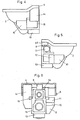
- water closet 1 has essentially the shape of a conventional toilet, which is mounted on a wall.
- a lavatory body 2 is preferably made of ceramic and has a flushing rim 3, with a flushing channel 3a (FIG. Fig. 8 ) and a rear part 4, which as can be seen, a substantially flat closed surface 35 which is located above the flushing rim 3.
- the transition from the rinsing edge 3 to the surface 35 is fluid over an inclined surface 36.
- a hair dryer arm 5 and a shower arm 6 are arranged at the rear, which protrude through openings of an insert 37.
- the insert 37 also forms a suction opening 7, through which air can be sucked.
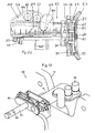
- a support frame 15 is arranged, which as can be seen forms a three-dimensional frame and on which the toilet body 2 is screwed.
- the support frame 15 also has two holes 19, where it is to be attached to a wall, for example a frame.
- the support frame 15 thus serves for fastening the toilet body 2. It is designed so that a flushing water pipe 17 and a drain pipe 18 are freely accessible from behind for connection.
- a flush pipe 31 and to the drain pipe 18, a drain pipe 32 is connected.
- the flushing of the toilet bowl body by means of a flush-mounted cistern 33 via the flushing pipe 31.
- the flushing can also be done in other ways, for example by means of a pressure washer.
- the required functional elements are attached. These functional elements are in particular in the 4 to 6 shown.
- One of these functional elements is a Boiler 14 in which the water for a sub-shower 9 is heated. The heated water passes through a pump 13 and a line not shown here to the shower arm 6.
- Another functional element is a Fön owned 11, for example, has a fan, not shown here, with the hot air are supplied to the hair dryer 5 via a line, not shown here can.
- Another functional unit is a suction device 12, which is connected to the suction opening 7 via a line or a channel, not shown here. With this suction unit 12 bad air can be sucked out of the toilet bowl 2.
- the lower shower 9, the Fön owned 11 and the suction device 12 form a module 34 which is used as a unit from behind and releasably secured, for example, not shown here locking means on the support frame 15.
- the module 34 can thus be used as a unit and in the case of a revision also removed again.
- the module 34 can also be retrofitted as a unit.
- the water closet 1 could thus be installed without this module 34 and would be readily usable as a water closet.
- the control of said functional units by means of electronic control elements 10 and 16, which according to the 4 and 5 are attached laterally on the support frame 15.
- the operation of the functional elements takes place on an operating device 46 which has keys 8 for switches not shown here. In principle, however, a remote control would be possible.
- the operating device 46 is located as shown laterally below one of the edges 4a.
- the operating device 46 is relatively inconspicuous but still easily accessible and thus ergonomically arranged.
- the operating device 46 may also be part of the module 34.
- the functional elements are according to Fig. 7 with a shuttering 21 covered and thus not visible when mounted water closet.
- the cover 21 consists of a plastic shell 22, which are attached from below to the toilet body 2 and releasably secured by means of fastening members 26 and 27 on this body.
- the fastening parts 26 and 27 are, for example, latching parts which can be releasably latched to corresponding parts of the toilet seat body. These are arranged so that the connecting parts are not visible from the outside.
- the toilet 1 can optionally with a Aufputz Fashionkasten 25 according to Fig. 7 or a concealed cistern 33 according Fig. 8 be equipped.
- a Aufputz Fashionkasten 25 according to Fig. 7
- a concealed cistern 33 according Fig. 8 be equipped.
- an adapter 24 is provided which consists of two shell parts 23 which are attached to the back of the lavatory body 2 and which form a passage 39 for the flushing pipe.
- the Aufputz Fashionkasten 25 is thus attached to the upper side of the adapter 24.
- the flushing pipe not shown here, leads to the flushing stub 17.
- the concealed cistern 33, the flushing elbow 31 and the drainage pipe 32 are fastened to a frame 40, which is only indicated here, which is supported on a building wall 41 and which is covered, for example, by means of a plaster wall 42. Behind the gypsum wall is thus the flushing device and the drain line 32.
- the functional elements and the lines required for this purpose are, as mentioned above, arranged below the rear part 4.
- the interface 43 in which the connections of the individual lines and connections takes place. These connections also include the electrical line connections and the water supply to the boiler.
- the interface 43 is also the connection of the support frame 15 with the building wall or the frame 40th
- a per se conventional seat ring 28 is arranged folded up on the toilet bowl 2.
- the shower arm 6 is in the Fig. 8 shown telescopically extended and directed obliquely downward, such that an indicated shower jet 44 is directed against the opening of the seat ring 28.
- the sub-shower 9, to which the shower arm 6 is attached is installed at the rear in a chamber 30, which is located above a flushing opening 45.
- the arrangement of the flushing arm 6 above the flushing opening 45 is advantageous for hygienic reasons.
- the mounting from the back side facilitates the assembly and also a revision.
- the sub-shower 9 can also be retrofitted as explained.
- the water closet 1 can thus be first mounted without a shower 9.
- the water closet 1 is removed and the lower shower 9 with the required further functional elements inserted from the rear side into the chamber 30.
- the toilet 1 is reassembled and can now be used with a shower.
- the entire module 34 is retrofitted.
- the toilet 1 is then also provided with an extraction.
- the Fig. 9 to 16 show a water closet 50 according to a variant.
- This has a toilet bowl 51 preferably made of ceramic, which has an opening 56 in a flushing rim 57, like the Fig. 13 clearly recognizable.
- console 84 a shower unit 62 mounted, which has an extendable shower arm 64 and an extendable hair dryer 63.
- the shower unit 62 is located in a chamber 53, which is arranged under a raised rear part 52 of the toilet seat 51.
- This chamber 53 which accommodates the shower unit 62, is open at a rear side 55 of the toilet seat 51.
- this chamber 53 is also laterally via an opening 61st open like that FIGS. 13 and 14 reveal.
- the space 53 is accessible through the opening 54.
- the shower unit 62 When mounting the shower unit 62 is inserted through the opening 54 in the chamber 53 and secured to the console 84 at the flushing rim 57. If the lavatory body 51 is mounted and a revision of the shower unit 62 is required, the shower unit 62 can be removed through the lateral opening 61 after removal of the casing 21 and finally replaced. The toilet body 51 thus does not have to be removed from the building wall for a revision of the shower unit 62.
- the lavatory body 51 has in the flushing edge 57 a conventional flushing channel, which with a Spülrohrstutzen 59 to the flushing pipe 31 (FIGS. Fig. 8 ) is connectable.
- the rinse water is supplied with a cistern 33 or 25, or by means of a flush valve.
- Below the Spülrohrstutzens 59 is a conventional outlet pipe 58, which is to be connected to a not shown here drain pipe.
- a support frame according to the first variant is not provided in this toilet body 51.
- the initially mentioned formwork 21 is in the FIGS. 13 and 14 omitted.
- the toilet body 51 is preferably made of ceramic.
- the rear part 52 and the flushing rim 57 are thus visible from the outside and easy to clean ceramic areas of the water closet 50 after attaching the shuttering 21.
- the in the FIGS. 11 and 12 shown shower unit 62 has a housing 76 which is releasably attached to a bracket 84.
- a drive 100 is mounted with two drive motors 66 and 67, with the shower arm 64 and the Fönarm 63 independently and can be retracted independently.
- the shower arm 64 and the hair dryer arm 63 are shown in the rest position in the retracted state.
- the Fig. 12 shows the shower arm 64 in the extended position.
- the power transmission of the drive motors 66 and 67 on the shower arm 64 and the Fönarm 63 via not shown here bands.
- two ports 69 and 70 are attached, which are connected to water lines, not shown here. shower water and rinse water can be supplied via these connections 69 and 70, as will be explained in more detail below. Via a line 68 of the shower unit 62 hot air for the hair dryer arm 63 are supplied.
- the console 84 has according to the FIGS. 11 and 12 a rear plate 77 on which rearwardly projecting pins 74 are integrally formed, to which the housing 76 is releasably secured.
- a front plate 79 is connected via pins 78 to the rear plate 77, in particular screwed, and this is the back in the region of the opening 56 at the flushing edge 57 at.
- a cover member 80 is attached to the console 84 with further pins 83, which seals the opening 56 on the inside of the flushing rim 57.
- a circumferential rubber-elastic sealing strip 83 is arranged, which according to the FIGS. 9 and 10 on the inside 94 abuts.
- the cover member 80 and the sealing tape 83 are removable and interchangeable.
- the cover 80 has an opening 82 for the shower arm 64 and an opening 81 for the hair dryer arm 63.
- a sealing ring 85 such as Fig. 10 shows.
- This sealing ring 85 seals the shower arm 64 or the hair dryer arm 63 in a watertight manner relative to the cover part 80.
- Both the shower arm 64 and the hair dryer arm 63 are closed at the front. In the resting position according to Fig. 11 the breakthrough 56 is thus completely through the Cover member 80 and the shower arm 64 and the hair dryer 63 closed. So dirty water can not get behind the opening 56. This is essential for hygienic reasons.
- the shower arm 64 and the Fönarm 63 are arranged above the flushing channel, the shower unit 62 is basically protected against contamination of contaminated rinse water.
- FIG. 10 shows the Spülrohrstutzen 59 in a channel 98, which leads to flushing nozzles 99, of which only one is shown here.
- flushing nozzles 99 Through this flushing nozzles 99, the rinse water flows behind a rim 57a down into the toilet bowl.
- the opening 56 is arranged at a distance from this edge 57a above this and protected against splashing water.
- the chamber 53 is arranged, which receives the unit 62. This is, as mentioned, with the bracket 84 releasably attached to the toilet seat body 51 and can be mounted with the toilet seat body 51 through the side openings 61 (FIGS. Fig. 14 ).
- the drive 100 is according to FIG. 11 arranged in a housing part 76a and forms with this a unit which is attached along a parting line 101 releasably attached to a front housing part 76b, for example, snapped.
- the shower room 64 and the hair dryer room 63 must be decoupled from the drive 100.
- the shower room 64 and the hair dryer arm 63 are connected to the drive 100 by means of a detent connection, not shown here.
- the drive 100 can then be for revision or replacement be removed. Also in this way the shower arm 64 and the hair dryer arm 64 can be exchanged and revised.
- the operation of the shower unit 62 is based on the schematic FIGS. 15 and 16 explained in more detail below.
- the shower arm 64 is mounted in a displaceable manner in a channel 94 of the housing 76. He is in the Fig. 15 shown in the rest position and thus in the retracted position. In the Fig. 16 the shower arm 64 is shown in an extended position. At the front end of the shower arm 64 has two spaced apart and upwardly directed openings 65 and 65a. The opening 65 is connected via a channel 96 with a multi-way valve 88 and finally with a water pump, not shown here. The further channel 87 leads to a front opening 65a and is also connected via the multi-way valve 88 with said water pump. On the operating device 46 ( Fig.
- the multi-way valve 88 can be adjusted so that either the water exits through the channel 86 at the opening 85 or via the channel 87 at the opening 65 a.
- the temperature of the water can also be adjusted.
- a rinsing nozzle 90 is arranged in a front region, to which a purge line 89 is connected, which is also connected to the water pump, not shown here.
- the rinse nozzle 90 is directed downwards and opens into a space 97 (FIG. Fig. 16 ), which covers the two openings 65 and 65a in the rest position of the shower arm 64.
- rinsing water is supplied via the line 89 to the nozzle 90 and the shower arm 64 is rinsed as a pre-rinse with a rinsing jet 91.
- the extended shower arm 64 according Fig. 16 is thus flushed and cleaned anyway.
- a shower jet 92 is generated.
- the nozzle 65 is used for the usual anal shower.
- the nozzle 65a can be used as a so-called lady-nozzle.
- the shower arm 64 After showering the shower arm 64 is again in the in Fig. 15 retired shown rest position. In this case, rinse water is again supplied via the nozzle 90 and the shower arm 64 is cleaned.
- the channels 86 and 87 are filled with water at a pressure so that no rinse water can penetrate through the nozzles 65 and 65a into the channels 86 and 87.
- the control takes place via the multiway valve 88.
- Such valves are known per se to those skilled in the art.
Claims (12)
- Water-closet comprenant un corps de WC (51), qui présente un bord de lavage (57), une arrivée (59) et un écoulement (58) pour l'eau de lavage et qui peut être raccordé à un dispositif de lavage (25, 33), comprenant des éléments fonctionnels qui comprennent au moins une douche inférieure (9) avec un bras de douche (64), un dispositif de commande (12, 16) pour la douche inférieure (9) et un dispositif de commande (46), le bord de lavage (57) présentant un percement (56) pour la douche inférieure (9) et derrière le percement (56), dans une partie arrière (52) du corps de WC (51) étant disposée une chambre (3) qui présente pour le montage et le démontage de la douche inférieure (9) au moins une ouverture (54, 61), caractérisé en ce que la douche inférieure (62) est réalisée sous forme d'unité de douche et présente au moins un bras de douche (64), un entraînement (66) pour le bras de douche (64) et un boîtier (76), en ce que cette unité (62) peut être montée et démontée dans la chambre (53) du corps de WC (51), en ce que le percement (56) pour la douche inférieure (9) est disposé au-dessus du canal de lavage (98) et en ce que l'unité de douche (62) est fixée dans ce percement (56) avec une console (84).
- Water-closet selon la revendication 1, caractérisé en ce que la partie arrière (52) est tirée vers le haut par rapport au bord de lavage (57) du corps de WC (51).
- Water-closet selon la revendication 1 ou 2, caractérisé en ce que la chambre (53) est ouverte au moins sur la face arrière du corps de WC (51) et la douche inférieure (9) peut être insérée par l'arrière dans la chambre (53).
- Water-closet selon la revendication 3, caractérisé en ce que la douche inférieure (9) est étanchéifiée vis-à-vis des éclaboussures d'eau du côté de la cuvette.
- Water-closet selon l'une quelconque des revendications 1 à 4, caractérisé en ce que le corps de WC (51) se compose de céramique et en ce que des éléments fonctionnels (12, 16, 9) sont recouverts par un coffrage (22).
- Water-closet selon l'une quelconque des revendications 1 à 5, caractérisé en ce que le coffrage (22) est en plastique.
- Water-closet selon l'une quelconque des revendications 1 à 6, caractérisé en ce que la douche inférieure (62) présente une buse de lavage (90), avec laquelle au moins le bras de douche (64) est pré-lavé et/ou post-lavé lors de son déploiement et de sa rétraction.
- Water-closet selon la revendication 7, caractérisé en ce que de l'eau de lavage est guidé vers la buse de lavage (90) pour le nettoyage de la tête de douche dans le bras de douche (64).
- Water-closet selon la revendication 1, caractérisé en ce que ladite unité de douche présente en outre un bras de sèche-cheveux déployable ainsi qu'une conduite (68) pour de l'air chaud.
- Water-closet selon la revendication 1, caractérisé en ce que l'unité de douche (62) est posée de manière amovible sur la console (84).
- Water-closet selon la revendication 1, dans lequel le corps de WC (51) présente, pour l'arrivée (59) d'eau de lavage, une tubulure pour le raccordement d'un tuyau de lavage et pour l'écoulement (58), une tubulure pour le raccordement d'un tuyau d'écoulement, caractérisé en ce que le bord de lavage (57) présente un percement (56) pour le support de la douche inférieure (62) et en ce que derrière ce percement (56) est disposée la chambre (53), qui est ouverte pour le montage de la douche inférieure (62).
- Water-closet selon la revendication 11, caractérisé en ce que l'espace (53) sur le côté arrière (55) et/ou latéral est ouvert.
Applications Claiming Priority (4)
| Application Number | Priority Date | Filing Date | Title |
|---|---|---|---|
| CH01775/00A CH694468A5 (de) | 2000-09-13 | 2000-09-13 | Wasserklosett. |
| CH177500 | 2000-09-13 | ||
| EP01960057A EP1317586B1 (fr) | 2000-09-13 | 2001-09-12 | W.-c. |
| PCT/CH2001/000551 WO2002022971A1 (fr) | 2000-09-13 | 2001-09-12 | W.-c. |
Related Parent Applications (2)
| Application Number | Title | Priority Date | Filing Date |
|---|---|---|---|
| EP01960057.6 Division | 2001-09-12 | ||
| EP01960057A Division EP1317586B1 (fr) | 2000-09-13 | 2001-09-12 | W.-c. |
Publications (4)
| Publication Number | Publication Date |
|---|---|
| EP1491693A2 EP1491693A2 (fr) | 2004-12-29 |
| EP1491693A3 EP1491693A3 (fr) | 2005-08-03 |
| EP1491693B1 true EP1491693B1 (fr) | 2009-12-30 |
| EP1491693B2 EP1491693B2 (fr) | 2019-03-20 |
Family
ID=4566225
Family Applications (3)
| Application Number | Title | Priority Date | Filing Date |
|---|---|---|---|
| EP04021610A Expired - Lifetime EP1491692B1 (fr) | 2000-09-13 | 2001-09-12 | W.c. |
| EP04021611.1A Expired - Lifetime EP1491693B2 (fr) | 2000-09-13 | 2001-09-12 | W.c. |
| EP01960057A Revoked EP1317586B1 (fr) | 2000-09-13 | 2001-09-12 | W.-c. |
Family Applications Before (1)
| Application Number | Title | Priority Date | Filing Date |
|---|---|---|---|
| EP04021610A Expired - Lifetime EP1491692B1 (fr) | 2000-09-13 | 2001-09-12 | W.c. |
Family Applications After (1)
| Application Number | Title | Priority Date | Filing Date |
|---|---|---|---|
| EP01960057A Revoked EP1317586B1 (fr) | 2000-09-13 | 2001-09-12 | W.-c. |
Country Status (6)
| Country | Link |
|---|---|
| EP (3) | EP1491692B1 (fr) |
| AT (3) | AT5466U1 (fr) |
| AU (1) | AU2001281666A1 (fr) |
| CH (1) | CH694468A5 (fr) |
| DE (3) | DE20112302U1 (fr) |
| WO (1) | WO2002022971A1 (fr) |
Cited By (1)
| Publication number | Priority date | Publication date | Assignee | Title |
|---|---|---|---|---|
| EP2568089B1 (fr) | 2011-09-12 | 2019-10-30 | Geberit International AG | Utilisation d'un dispositif de raccordement pour un WC de douche et d'un WC de douche |
Families Citing this family (19)
| Publication number | Priority date | Publication date | Assignee | Title |
|---|---|---|---|---|
| FR2893644A1 (fr) * | 2005-11-23 | 2007-05-25 | Pierre Henri Sassier | Siege wc a douchette et bidet thermostates equipe d'un verin auto-nettoyant |
| JP2007255155A (ja) * | 2006-03-24 | 2007-10-04 | Matsushita Electric Works Ltd | 局部洗浄装置付便器 |
| JP4925264B2 (ja) * | 2006-04-24 | 2012-04-25 | パナソニック株式会社 | 局部洗浄装置付便器 |
| EP2067901B2 (fr) † | 2007-12-05 | 2018-07-25 | Geberit International AG | Installation dotée d'un dispositif de lavage et d'une cuvette de W.-C., kit de montage destiné au montage d'une telle installation et procédé de montage d'une telle installation |
| DE202009018223U1 (de) | 2008-08-29 | 2011-05-19 | Spannring Dusch-Wc; Inhaber Alfred Spannring | Hermetisch verschlossener Wasserbehälter |
| DE102009005319B4 (de) * | 2009-01-16 | 2015-10-15 | Tece Gmbh | Multifunktionale Toilettenanordnung |
| DE102009030490A1 (de) | 2009-06-24 | 2010-12-30 | Tece Gmbh | Multifunktionale Toilettenanordnung |
| CH704333A2 (de) | 2011-01-13 | 2012-07-13 | Mueller Haustechnik Ag M | Drehschieberpumpe zum Pumpen einer Flüssigkeit, insbesondere für ein Wasserklosett mit Unterdusche. |
| DE102012211655A1 (de) * | 2012-07-04 | 2014-01-09 | Tece Gmbh | Dusch - WC |
| PT2700760E (pt) * | 2012-08-20 | 2015-02-24 | Geberit Int Ag | Sanita com chuveiro, com braço de chuveiro desmontável |
| DE202013001133U1 (de) | 2013-02-06 | 2014-03-07 | Carsten Willers Consulting Gmbh | WC mit Unterdusche |
| WO2014170465A1 (fr) | 2013-04-18 | 2014-10-23 | Tece Gmbh | Wc muni d'une douchette intime intégrée dans le distributeur d'eau de rinçage |
| JP6183649B2 (ja) | 2013-08-07 | 2017-08-23 | Toto株式会社 | トイレ装置 |
| KR102121494B1 (ko) | 2013-09-30 | 2020-06-11 | 프레사노 아게 | 변기 몸체를 위한 마운팅 플레이트 |
| DE202014101888U1 (de) | 2013-10-15 | 2015-01-16 | Tece Gmbh | Dusch-WC mit Havarievorrichtung |
| CN105369875B (zh) * | 2015-11-10 | 2018-05-22 | 嘉兴市翔英五金塑料有限公司 | 一种智能座便器 |
| EP3585950B1 (fr) * | 2017-02-21 | 2022-03-30 | MAG Aerospace Industries, LLC | Anneau de rinçage de bidet |
| WO2019113714A1 (fr) * | 2017-12-11 | 2019-06-20 | Presano Ag | Corps de toilettes avec détartrage de chauffe-eau |
| WO2019210435A1 (fr) * | 2018-05-03 | 2019-11-07 | Presano Ag | Ensemble wc-douche |
Family Cites Families (22)
| Publication number | Priority date | Publication date | Assignee | Title |
|---|---|---|---|---|
| US1935201A (en) * | 1933-01-27 | 1933-11-14 | Callejo Modesto | Lavatory fixture |
| US2743460A (en) * | 1953-08-03 | 1956-05-01 | Leonard W Youngstrom | Adjustable connector for tank and bowl of a close coupled water-closet combination |
| US2762058A (en) * | 1954-09-24 | 1956-09-11 | American Radiator & Standard | Sanitary fixture |
| CH345312A (de) * | 1957-03-13 | 1960-03-15 | Maurer Hans | Klosetteinrichtung, an deren Klosettschüssel eine zum Waschen der untern Körperteile des Benützers bestimmte Spritzvorrichtung angebracht ist |
| CH471292A (de) * | 1967-03-31 | 1969-04-15 | Maurer Hans | Klosetteinrichtung mit einer zum Waschen der unteren Körperteile bestimmten Spritzvorrichtung |
| DE2541009A1 (de) * | 1975-09-13 | 1977-03-17 | Mfb Neuwerk Mech Fenster | Vorrichtung zur betaetigung von unterduschen |
| DE2646021C3 (de) * | 1976-10-12 | 1979-05-23 | Hans Zollikerberg Zuerich Maurer (Schweiz) | Unterdusche für Klosetts |
| EP0177967B1 (fr) † | 1984-10-12 | 1991-07-17 | Toto Ltd. | Salle de bains |
| US4628548A (en) * | 1985-03-23 | 1986-12-16 | Toto Ltd. | Device and method of moving and controlling the position of a slidable body such as used for body cleansing |
| JP2545843B2 (ja) * | 1987-03-30 | 1996-10-23 | アイシン精機株式会社 | 人体局部洗浄装置の水回路 |
| DE8902318U1 (fr) * | 1989-02-27 | 1989-04-06 | Wisan Technik Ag, Zug, Ch | |
| DE9103211U1 (fr) | 1990-04-03 | 1991-06-13 | Geberit Ag, Jona, St.Gallen, Ch | |
| JP2806032B2 (ja) * | 1990-10-05 | 1998-09-30 | 東陶機器株式会社 | 洗浄給水装置 |
| KR960010618Y1 (ko) * | 1991-09-06 | 1996-12-20 | 홍종훈 | 좌변기용 세척수 공급장치 |
| JP2646928B2 (ja) * | 1992-02-28 | 1997-08-27 | 株式会社イナックス | 便器付属品の設置構造 |
| JPH05263455A (ja) * | 1992-03-17 | 1993-10-12 | Inax Corp | 洋風便器設備 |
| GR1002416B (el) | 1995-04-07 | 1996-08-19 | Συνθετη λεκανη wc - μπιντε, με μεσολαβηση συστηματος ενσωματωμενων σωληνωτων αγωγων. | |
| GR1002417B (el) | 1995-04-07 | 1996-08-19 | Συνθετη λεκανη wc-μπιντε, με ενσωματωμενους στην λεκανη αγωγους. | |
| JP3700739B2 (ja) * | 1996-02-21 | 2005-09-28 | アイシン精機株式会社 | 衛生洗浄装置 |
| US5813060A (en) * | 1996-09-12 | 1998-09-29 | Klopocinski; Stanislaw | Multifunction toilet |
| US6073275A (en) † | 1996-09-12 | 2000-06-13 | Klopocinski; Stanislaw | Multifunction toilet |
| FR2764914B1 (fr) * | 1997-06-23 | 1999-08-06 | Allia | Dispositif de fixation d'un reservoir de chasse d'eau |
-
2000
- 2000-09-13 CH CH01775/00A patent/CH694468A5/de not_active IP Right Cessation
-
2001
- 2001-07-26 DE DE20112302U patent/DE20112302U1/de not_active Expired - Lifetime
- 2001-08-06 AT AT0061801U patent/AT5466U1/de not_active IP Right Cessation
- 2001-09-12 WO PCT/CH2001/000551 patent/WO2002022971A1/fr active IP Right Grant
- 2001-09-12 AT AT01960057T patent/ATE355421T1/de active
- 2001-09-12 EP EP04021610A patent/EP1491692B1/fr not_active Expired - Lifetime
- 2001-09-12 DE DE50115290T patent/DE50115290D1/de not_active Expired - Lifetime
- 2001-09-12 EP EP04021611.1A patent/EP1491693B2/fr not_active Expired - Lifetime
- 2001-09-12 AT AT04021611T patent/ATE453764T1/de active
- 2001-09-12 EP EP01960057A patent/EP1317586B1/fr not_active Revoked
- 2001-09-12 DE DE50112129T patent/DE50112129D1/de not_active Expired - Lifetime
- 2001-09-12 AU AU2001281666A patent/AU2001281666A1/en not_active Abandoned
Cited By (1)
| Publication number | Priority date | Publication date | Assignee | Title |
|---|---|---|---|---|
| EP2568089B1 (fr) | 2011-09-12 | 2019-10-30 | Geberit International AG | Utilisation d'un dispositif de raccordement pour un WC de douche et d'un WC de douche |
Also Published As
| Publication number | Publication date |
|---|---|
| AT5466U1 (de) | 2002-07-25 |
| DE50112129D1 (de) | 2007-04-12 |
| ATE453764T1 (de) | 2010-01-15 |
| EP1317586A1 (fr) | 2003-06-11 |
| EP1491692B1 (fr) | 2012-06-13 |
| EP1491693A2 (fr) | 2004-12-29 |
| AU2001281666A1 (en) | 2002-03-26 |
| EP1491693A3 (fr) | 2005-08-03 |
| EP1491693B2 (fr) | 2019-03-20 |
| CH694468A5 (de) | 2005-01-31 |
| DE20112302U1 (de) | 2001-10-11 |
| ATE355421T1 (de) | 2006-03-15 |
| EP1491692A2 (fr) | 2004-12-29 |
| WO2002022971A1 (fr) | 2002-03-21 |
| DE50115290D1 (de) | 2010-02-11 |
| EP1317586B1 (fr) | 2007-02-28 |
| EP1491692A3 (fr) | 2005-08-03 |
Similar Documents
| Publication | Publication Date | Title |
|---|---|---|
| EP1491693B1 (fr) | W.c. | |
| EP2986787B1 (fr) | Wc muni d'une douchette intime intégrée dans le distributeur d'eau de rinçage | |
| EP2071087B1 (fr) | Toilettes autonettoyantes | |
| EP3006633B1 (fr) | Système de toilettes multifonctionnel | |
| EP2067901B1 (fr) | Installation dotée d'un dispositif de lavage et d'une cuvette de W.-C., kit de montage destiné au montage d'une telle installation et procédé de montage d'une telle installation | |
| EP2938790B1 (fr) | Élément rapporté pour wc comportant un dispositif de douche | |
| EP2531661A1 (fr) | Unité technique pour dispositif sanitaire | |
| EP1507935A1 (fr) | Chasse d'eau de wc pourvue d'un bras pour le rincage d'une cuvette de wc | |
| EP3748094B1 (fr) | Wc douche avec dispositif de sécurité contre l'aspiration d'eau sale dans le tuyau d'eau potable | |
| DE102014109276B4 (de) | WC-Modul mit Unterputzspülkasten für ein Dusch-WC mit integriertem, abgesichertem Frischwasseranschluss | |
| EP1335076B1 (fr) | Accessoire d'écoulement pour un dispositif sanitaire, en particulier un urinoir | |
| DE10025348A1 (de) | Kombinierte Toilette | |
| DE202011051490U1 (de) | Wasch-WC | |
| DE102009005319A1 (de) | Multifunktionale Toilettenanordnung | |
| EP0024743A2 (fr) | Lit pour malade et installation de WC s'adaptant dessus | |
| DE102013207053A1 (de) | Dusch-WC | |
| DE3932126A1 (de) | Toilettenstuhl mit wasserspuelung | |
| EP0162397A2 (fr) | Cellule sanitaire | |
| EP1552778B1 (fr) | Dispositif d'urinoir à monter sur un W.C. comprenant un siège et/ou un couvercle | |
| WO1991016510A1 (fr) | Siege d'aisances a cuvette pivotante | |
| WO2024008957A1 (fr) | Anneau de siège de wc | |
| DE20318340U1 (de) | WC-Schüssel mit Wasservorhang | |
| DE4424529A1 (de) | WC-Bidet-Kombination zu einem nebeneinanderliegenden WC-Bidet-Kombinations-Anbausystem ausgebildet | |
| EP4317623A1 (fr) | Dispositif de chasse sous pression d'un cuvette de wc, cuvette de wc dotée d'un tel dispositif et son utilisation | |
| DE102004005759A1 (de) | Verfahren und Einrichtung zum Dosieren und Zuführen eines Mediums in eine Sanitäreinrichtung |
Legal Events
| Date | Code | Title | Description |
|---|---|---|---|
| PUAI | Public reference made under article 153(3) epc to a published international application that has entered the european phase |
Free format text: ORIGINAL CODE: 0009012 |
|
| AC | Divisional application: reference to earlier application |
Ref document number: 1317586 Country of ref document: EP Kind code of ref document: P |
|
| AK | Designated contracting states |
Kind code of ref document: A2 Designated state(s): AT BE CH CY DE DK ES FI FR GB GR IE IT LI LU MC NL PT SE TR |
|
| RAP1 | Party data changed (applicant data changed or rights of an application transferred) |
Owner name: GEBERIT BALENA AG |
|
| PUAL | Search report despatched |
Free format text: ORIGINAL CODE: 0009013 |
|
| AK | Designated contracting states |
Kind code of ref document: A3 Designated state(s): AT BE CH CY DE DK ES FI FR GB GR IE IT LI LU MC NL PT SE TR |
|
| 17P | Request for examination filed |
Effective date: 20050825 |
|
| AKX | Designation fees paid |
Designated state(s): AT BE CH CY DE DK ES FI FR GB GR IE IT LI LU MC NL PT SE TR |
|
| 17Q | First examination report despatched |
Effective date: 20070830 |
|
| RAP1 | Party data changed (applicant data changed or rights of an application transferred) |
Owner name: GEBERIT TECHNIK AG |
|
| GRAP | Despatch of communication of intention to grant a patent |
Free format text: ORIGINAL CODE: EPIDOSNIGR1 |
|
| GRAS | Grant fee paid |
Free format text: ORIGINAL CODE: EPIDOSNIGR3 |
|
| GRAA | (expected) grant |
Free format text: ORIGINAL CODE: 0009210 |
|
| RAP1 | Party data changed (applicant data changed or rights of an application transferred) |
Owner name: GEBERIT INTERNATIONAL AG |
|
| AC | Divisional application: reference to earlier application |
Ref document number: 1317586 Country of ref document: EP Kind code of ref document: P |
|
| AK | Designated contracting states |
Kind code of ref document: B1 Designated state(s): AT BE CH CY DE DK ES FI FR GB GR IE IT LI LU MC NL PT SE TR |
|
| REG | Reference to a national code |
Ref country code: GB Ref legal event code: FG4D Free format text: NOT ENGLISH |
|
| REG | Reference to a national code |
Ref country code: CH Ref legal event code: EP Ref country code: CH Ref legal event code: NV Representative=s name: ISLER & PEDRAZZINI AG |
|
| REG | Reference to a national code |
Ref country code: IE Ref legal event code: FG4D |
|
| REF | Corresponds to: |
Ref document number: 50115290 Country of ref document: DE Date of ref document: 20100211 Kind code of ref document: P |
|
| PG25 | Lapsed in a contracting state [announced via postgrant information from national office to epo] |
Ref country code: FI Free format text: LAPSE BECAUSE OF FAILURE TO SUBMIT A TRANSLATION OF THE DESCRIPTION OR TO PAY THE FEE WITHIN THE PRESCRIBED TIME-LIMIT Effective date: 20091230 Ref country code: SE Free format text: LAPSE BECAUSE OF FAILURE TO SUBMIT A TRANSLATION OF THE DESCRIPTION OR TO PAY THE FEE WITHIN THE PRESCRIBED TIME-LIMIT Effective date: 20091230 |
|
| REG | Reference to a national code |
Ref country code: IE Ref legal event code: FD4D |
|
| PG25 | Lapsed in a contracting state [announced via postgrant information from national office to epo] |
Ref country code: PT Free format text: LAPSE BECAUSE OF FAILURE TO SUBMIT A TRANSLATION OF THE DESCRIPTION OR TO PAY THE FEE WITHIN THE PRESCRIBED TIME-LIMIT Effective date: 20100430 Ref country code: ES Free format text: LAPSE BECAUSE OF FAILURE TO SUBMIT A TRANSLATION OF THE DESCRIPTION OR TO PAY THE FEE WITHIN THE PRESCRIBED TIME-LIMIT Effective date: 20100410 |
|
| PLBI | Opposition filed |
Free format text: ORIGINAL CODE: 0009260 |
|
| PG25 | Lapsed in a contracting state [announced via postgrant information from national office to epo] |
Ref country code: CY Free format text: LAPSE BECAUSE OF FAILURE TO SUBMIT A TRANSLATION OF THE DESCRIPTION OR TO PAY THE FEE WITHIN THE PRESCRIBED TIME-LIMIT Effective date: 20091230 Ref country code: IE Free format text: LAPSE BECAUSE OF FAILURE TO SUBMIT A TRANSLATION OF THE DESCRIPTION OR TO PAY THE FEE WITHIN THE PRESCRIBED TIME-LIMIT Effective date: 20091230 Ref country code: GR Free format text: LAPSE BECAUSE OF FAILURE TO SUBMIT A TRANSLATION OF THE DESCRIPTION OR TO PAY THE FEE WITHIN THE PRESCRIBED TIME-LIMIT Effective date: 20100331 |
|
| 26 | Opposition filed |
Opponent name: ABLETT, GRAHAM KEITH Effective date: 20100930 |
|
| PLAX | Notice of opposition and request to file observation + time limit sent |
Free format text: ORIGINAL CODE: EPIDOSNOBS2 |
|
| PLAF | Information modified related to communication of a notice of opposition and request to file observations + time limit |
Free format text: ORIGINAL CODE: EPIDOSCOBS2 |
|
| PG25 | Lapsed in a contracting state [announced via postgrant information from national office to epo] |
Ref country code: DK Free format text: LAPSE BECAUSE OF FAILURE TO SUBMIT A TRANSLATION OF THE DESCRIPTION OR TO PAY THE FEE WITHIN THE PRESCRIBED TIME-LIMIT Effective date: 20091230 |
|
| PLAF | Information modified related to communication of a notice of opposition and request to file observations + time limit |
Free format text: ORIGINAL CODE: EPIDOSCOBS2 |
|
| PG25 | Lapsed in a contracting state [announced via postgrant information from national office to epo] |
Ref country code: MC Free format text: LAPSE BECAUSE OF NON-PAYMENT OF DUE FEES Effective date: 20100930 |
|
| PLBB | Reply of patent proprietor to notice(s) of opposition received |
Free format text: ORIGINAL CODE: EPIDOSNOBS3 |
|
| PG25 | Lapsed in a contracting state [announced via postgrant information from national office to epo] |
Ref country code: LU Free format text: LAPSE BECAUSE OF NON-PAYMENT OF DUE FEES Effective date: 20100912 |
|
| PG25 | Lapsed in a contracting state [announced via postgrant information from national office to epo] |
Ref country code: TR Free format text: LAPSE BECAUSE OF FAILURE TO SUBMIT A TRANSLATION OF THE DESCRIPTION OR TO PAY THE FEE WITHIN THE PRESCRIBED TIME-LIMIT Effective date: 20091230 |
|
| PLAB | Opposition data, opponent's data or that of the opponent's representative modified |
Free format text: ORIGINAL CODE: 0009299OPPO |
|
| R26 | Opposition filed (corrected) |
Opponent name: ABLETT, GRAHAM KEITH Effective date: 20100930 |
|
| PLAB | Opposition data, opponent's data or that of the opponent's representative modified |
Free format text: ORIGINAL CODE: 0009299OPPO |
|
| R26 | Opposition filed (corrected) |
Opponent name: ABLETT, GRAHAM KEITH Effective date: 20100930 |
|
| APBM | Appeal reference recorded |
Free format text: ORIGINAL CODE: EPIDOSNREFNO |
|
| APBP | Date of receipt of notice of appeal recorded |
Free format text: ORIGINAL CODE: EPIDOSNNOA2O |
|
| APAH | Appeal reference modified |
Free format text: ORIGINAL CODE: EPIDOSCREFNO |
|
| APBQ | Date of receipt of statement of grounds of appeal recorded |
Free format text: ORIGINAL CODE: EPIDOSNNOA3O |
|
| PGFP | Annual fee paid to national office [announced via postgrant information from national office to epo] |
Ref country code: GB Payment date: 20140923 Year of fee payment: 14 |
|
| PGFP | Annual fee paid to national office [announced via postgrant information from national office to epo] |
Ref country code: FR Payment date: 20140917 Year of fee payment: 14 |
|
| PGFP | Annual fee paid to national office [announced via postgrant information from national office to epo] |
Ref country code: NL Payment date: 20140922 Year of fee payment: 14 |
|
| PGFP | Annual fee paid to national office [announced via postgrant information from national office to epo] |
Ref country code: IT Payment date: 20140929 Year of fee payment: 14 |
|
| PGFP | Annual fee paid to national office [announced via postgrant information from national office to epo] |
Ref country code: BE Payment date: 20140917 Year of fee payment: 14 |
|
| PG25 | Lapsed in a contracting state [announced via postgrant information from national office to epo] |
Ref country code: IT Free format text: LAPSE BECAUSE OF NON-PAYMENT OF DUE FEES Effective date: 20150912 |
|
| GBPC | Gb: european patent ceased through non-payment of renewal fee |
Effective date: 20150912 |
|
| REG | Reference to a national code |
Ref country code: NL Ref legal event code: MM Effective date: 20151001 |
|
| REG | Reference to a national code |
Ref country code: FR Ref legal event code: ST Effective date: 20160531 |
|
| PG25 | Lapsed in a contracting state [announced via postgrant information from national office to epo] |
Ref country code: GB Free format text: LAPSE BECAUSE OF NON-PAYMENT OF DUE FEES Effective date: 20150912 |
|
| PG25 | Lapsed in a contracting state [announced via postgrant information from national office to epo] |
Ref country code: FR Free format text: LAPSE BECAUSE OF NON-PAYMENT OF DUE FEES Effective date: 20150930 Ref country code: NL Free format text: LAPSE BECAUSE OF NON-PAYMENT OF DUE FEES Effective date: 20151001 |
|
| PG25 | Lapsed in a contracting state [announced via postgrant information from national office to epo] |
Ref country code: BE Free format text: LAPSE BECAUSE OF NON-PAYMENT OF DUE FEES Effective date: 20150930 |
|
| APBU | Appeal procedure closed |
Free format text: ORIGINAL CODE: EPIDOSNNOA9O |
|
| PGFP | Annual fee paid to national office [announced via postgrant information from national office to epo] |
Ref country code: CH Payment date: 20180924 Year of fee payment: 18 Ref country code: AT Payment date: 20180918 Year of fee payment: 18 |
|
| PUAH | Patent maintained in amended form |
Free format text: ORIGINAL CODE: 0009272 |
|
| STAA | Information on the status of an ep patent application or granted ep patent |
Free format text: STATUS: PATENT MAINTAINED AS AMENDED |
|
| REG | Reference to a national code |
Ref country code: CH Ref legal event code: AELC |
|
| 27A | Patent maintained in amended form |
Effective date: 20190320 |
|
| AK | Designated contracting states |
Kind code of ref document: B2 Designated state(s): AT BE CH CY DE DK ES FI FR GB GR IE IT LI LU MC NL PT SE TR |
|
| REG | Reference to a national code |
Ref country code: DE Ref legal event code: R102 Ref document number: 50115290 Country of ref document: DE |
|
| REG | Reference to a national code |
Ref country code: CH Ref legal event code: PL |
|
| PG25 | Lapsed in a contracting state [announced via postgrant information from national office to epo] |
Ref country code: CH Free format text: LAPSE BECAUSE OF NON-PAYMENT OF DUE FEES Effective date: 20190930 Ref country code: LI Free format text: LAPSE BECAUSE OF NON-PAYMENT OF DUE FEES Effective date: 20190930 |
|
| REG | Reference to a national code |
Ref country code: AT Ref legal event code: MM01 Ref document number: 453764 Country of ref document: AT Kind code of ref document: T Effective date: 20190912 |
|
| PGFP | Annual fee paid to national office [announced via postgrant information from national office to epo] |
Ref country code: DE Payment date: 20200924 Year of fee payment: 20 |
|
| PG25 | Lapsed in a contracting state [announced via postgrant information from national office to epo] |
Ref country code: AT Free format text: LAPSE BECAUSE OF NON-PAYMENT OF DUE FEES Effective date: 20190912 |
|
| REG | Reference to a national code |
Ref country code: DE Ref legal event code: R071 Ref document number: 50115290 Country of ref document: DE |