EP1491693B1 - Water-closet - Google Patents
Water-closet Download PDFInfo
- Publication number
- EP1491693B1 EP1491693B1 EP04021611A EP04021611A EP1491693B1 EP 1491693 B1 EP1491693 B1 EP 1491693B1 EP 04021611 A EP04021611 A EP 04021611A EP 04021611 A EP04021611 A EP 04021611A EP 1491693 B1 EP1491693 B1 EP 1491693B1
- Authority
- EP
- European Patent Office
- Prior art keywords
- spray
- lavatory
- flushing
- upwardly directed
- arm
- Prior art date
- Legal status (The legal status is an assumption and is not a legal conclusion. Google has not performed a legal analysis and makes no representation as to the accuracy of the status listed.)
- Expired - Lifetime
Links
Images


Classifications
-
- E—FIXED CONSTRUCTIONS
- E03—WATER SUPPLY; SEWERAGE
- E03D—WATER-CLOSETS OR URINALS WITH FLUSHING DEVICES; FLUSHING VALVES THEREFOR
- E03D1/00—Water flushing devices with cisterns ; Setting up a range of flushing devices or water-closets; Combinations of several flushing devices
- E03D1/24—Low-level flushing systems
- E03D1/26—Bowl with flushing cistern mounted on the rearwardly extending end of the bowl
-
- E—FIXED CONSTRUCTIONS
- E03—WATER SUPPLY; SEWERAGE
- E03D—WATER-CLOSETS OR URINALS WITH FLUSHING DEVICES; FLUSHING VALVES THEREFOR
- E03D9/00—Sanitary or other accessories for lavatories ; Devices for cleaning or disinfecting the toilet room or the toilet bowl; Devices for eliminating smells
- E03D9/04—Special arrangement or operation of ventilating devices
- E03D9/05—Special arrangement or operation of ventilating devices ventilating the bowl
-
- E—FIXED CONSTRUCTIONS
- E03—WATER SUPPLY; SEWERAGE
- E03D—WATER-CLOSETS OR URINALS WITH FLUSHING DEVICES; FLUSHING VALVES THEREFOR
- E03D9/00—Sanitary or other accessories for lavatories ; Devices for cleaning or disinfecting the toilet room or the toilet bowl; Devices for eliminating smells
- E03D9/08—Devices in the bowl producing upwardly-directed sprays; Modifications of the bowl for use with such devices ; Bidets; Combinations of bowls with urinals or bidets; Hot-air or other devices mounted in or on the bowl, urinal or bidet for cleaning or disinfecting
Description
Die Erfindung betrifft ein Wasserklosett nach dem Oberbegriff des Anspruchs 1.The invention relates to a water closet according to the preamble of
Wasserklosetts mit Unterdusche, auch Dusche-WC genannt, sind in zahlreichen Ausführungen bekannt. Die Unterdusche weist in der Regel einen schwenkbaren oder teleskopisch ausfahrbaren Arm auf, der an einen Boiler angeschlossen ist. Mittels einer Pumpe kann warmes Wasser aus dem Boiler dem Duscharm zugeführt werden. Ein weiteres Funktionselement ist üblicherweise ein Fön, dessen Lufttemperatur regulierbar ist und der ein- und ausgeschaltet werden kann. Weiter kann eine Geruchsabsaugung vorgesehen sein, mit welcher Luft aus der Klosettschüssel abgesaugt werden kann. Die Betätigung der Funktionselemente erfolgt über Schalter, die in der Regel seitlich so angeordnet sind, dass sie gut erreichbar sind. Bei der Montage müssen die Funktionselemente an eine Stromquelle sowie an eine Wasserleitung angeschlossen werden. An solche Wasserklosetts werden hohe Anforderungen gestellt. Insbesondere müssen sie sicher sein und Fehlmanipulationen müssen ausgeschlossen werden. Die Installation und Montage soll möglichst einfach sein und eine Reinigung soll aus hygienischen Gründen einfach durchführbar sein.Water closets with under shower, also called shower-WC, are known in numerous designs. The sub-shower usually has a pivotable or telescopically extendable arm, which is connected to a boiler. By means of a pump warm water can be supplied from the boiler to the shower arm. Another functional element is usually a hair dryer whose air temperature is adjustable and which can be switched on and off. Furthermore, an odor extraction can be provided with which air can be sucked out of the toilet bowl. The actuation of the functional elements via switches, which are usually arranged laterally so that they are easily accessible. During assembly, the functional elements must be connected to a power source and to a water pipe. At such water closets high demands are made. In particular, they must be safe and mishandling must be ruled out. The installation and installation should be as simple as possible and a cleaning should be easy to carry out for hygienic reasons.
Die
Vom Anmelder wird ein Wasserklosett angeboten, bei welchem die Funktionselemente sowie ein Spülkasten in einem Aufsatz untergebracht sind, der auf der Rückseite des Klosettkörpers auf diesem befestigt ist. Dieses Wasserklosett erfüllt hohe Ansprüche, ist aber vergleichsweise voluminös und in der Herstellung aufwendig.The applicant provides a water closet in which the functional elements and a cistern are housed in an essay which is mounted on the back of the toilet seat body on this. This water closet meets high standards, but is relatively bulky and expensive to manufacture.
Durch die
Die gattungsbildende
Der Erfindung liegt die Aufgabe zugrunde, ein Wasserklosett der genannten Art zu schaffen, das wartungsfreundlich und bezüglich der Unterdusche reinigungsfreundlich und hygienisch ist.The invention has for its object to provide a water closet of the type mentioned, which is easy to maintain and clean and hygienic with respect to the shower.
Die Erfindung ist bei einem gattungsgemässen Wasserklosett gemäss Anspruch 1 gelöst.The invention is achieved in a generic water closet according to
Die Anwendung der Unterdusche in einer offenen Kammer ermöglicht den einfachen Ein- und Ausbau einer Duscheinheit für die Montage, eine Revision oder Reinigung.The application of the sub-shower in an open chamber allows easy installation and removal of a shower unit for assembly, a revision or cleaning.
Die Gestaltung ist dann besonders vorteilhaft, wenn gemäss einer Weiterbildung der Erfindung die Funktionselemente mittels einer Verschalung vorzugsweise aus Kunststoff abgedeckt sind. Für eine Revision kann diese Verschalung abgenommen werden.The design is particularly advantageous if, according to a development of the invention, the functional elements are covered by means of a casing, preferably made of plastic. For a revision, this casing can be removed.
Das Wasserklosett ist gemäss einer Weiterbildung ein Wandklosett und seine Rückseite ist vorzugsweise im wesentlichen eine Schnittstelle für die Befestigung des Klosettkörpers, für die Befestigung des Ablaufs und des Spülrohres sowie die Wasser- und Elektronikanschlüsse. Sämtliche Verbindungsstellen sind somit an der Rückseite des Wasserklosetts angeordnet. Dies ergibt eine kompakte Bauweise sowie eine einfachere Montage.The water closet is according to a development of a wall toilet and its back is preferably essentially an interface for the attachment of the toilet seat, for the attachment of the drain and the flushing pipe and the water and electronic connections. All joints are thus on the back of the water closet arranged. This results in a compact design and easier installation.
Nach einer Weiterbildung der Erfindung ist an der Rückseite des Wasserklosetts ein Adapter angeordnet, auf dem ein Spülkasten befestigt ist. Der Adapter ist im wesentlichen ebenfalls eine Verschalung und trägt den Spülkasten. Gemäss einer alternativen Ausführung ist der Spülkasten ein Unterputzspülkasten. Dies ermöglicht die Verwendung an sich bekannter Installationselemente, die einen Spülkasten sowie An- und Ablaufleitungen aufweist. Ein solches Installationselement kann beispielsweise hinter einer Gipswand angeordnet sein. Das erfindungsgemässe Wasserklosett kann somit wahlweise mit einem Unterputz- oder Aufputzspülkasten ausgerüstet werden.According to a development of the invention, an adapter is arranged on the back of the water closet, on which a cistern is attached. The adapter is also essentially a formwork and carries the cistern. According to an alternative embodiment, the cistern is a concealed cistern. This allows the use of known installation elements, which has a cistern and inlet and outlet pipes. Such an installation element may, for example, be arranged behind a plaster wall. The inventive water closet can thus be optionally equipped with a concealed or Aufputzspülkasten.
Weitere vorteilhafte Merkmale ergeben sich aus den abhängigen Patentansprüchen, der nachfolgenden Beschreibung sowie der Zeichnung.Further advantageous features emerge from the dependent claims, the following description and the drawings.
Ausführungsbeispiele der Erfindung werden nachfolgend anhand der Zeichnung näher erläutert. Es zeigen:
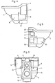
- Fig. 1
- eine räumliche Ansicht eines erfindungsgemässen Wasserklosetts,
- Fig. 2
- eine schematische Ansicht der Rückseite des Wasserklosetts,
- Fig. 3
- eine weitere Ansicht der Rückseite, wobei Funktionselemente weggelassen sind,
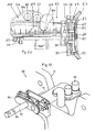
- Fig. 4-6
- weitere Ansichten des erfindungsgemässen Wasserklosetts, wobei auch hier Teile weggelassen sind,
- Fig. 7
- schematisch ein erfindungsgemässes Wasserklosett, wobei Teile der Verschalung einzeln gezeigt sind,
- Fig. 8
- ein Schnitt durch ein installiertes Wasserklosett,
- Fig. 9
- einen Teilschnitt durch ein Wasserklosett nach einer Variante, wobei die Unterdusche teilweise in Ansicht gezeigt ist,
- Fig. 10
- ein weiterer Teilschnitt durch das Wasserklosett nach der Variante,
- Fig. 11
- eine Draufsicht auf die Unterdusche,
- Fig. 12
- schematische eine räumliche Teilansicht des Wasserklosetts nach der Variante,
- Fig. 13
- eine räumliche Ansicht des Klosettkörpers,
- Fig. 14
- eine weitere Ansicht des Klosettkörpers,
- Fig. 15
- schematisch ein Längsschnitt durch einen Duscharm beim Vor- oder Nachspülen,
- Fig. 16
- schematisch einen Längsschnitt durch einen ausgefahrenen Duscharm in Duschfunktion und
- Fig. 17
- schematisch ein Querschnitt durch die Unterdusche sowie eine Teilaussicht des Klosettkörpers.
- Fig. 1
- a spatial view of an inventive water closet,
- Fig. 2
- a schematic view of the back of the water closet,
- Fig. 3
- another view of the back, with functional elements are omitted,
- Fig. 4-6
- further views of the water closet according to the invention, wherein also parts are omitted here,
- Fig. 7
- schematically a water closet according to the invention, wherein parts of the casing are shown individually,
- Fig. 8
- a section through an installed water closet,
- Fig. 9
- a partial section through a water closet according to a variant, wherein the sub-shower is shown partially in view,
- Fig. 10
- another partial section through the water closet according to the variant,
- Fig. 11
- a top view of the sub-shower,
- Fig. 12
- schematic partial view of the water closet according to the variant,
- Fig. 13
- a spatial view of the toilet seat body,
- Fig. 14
- another view of the toilet seat body,
- Fig. 15
- schematically a longitudinal section through a shower arm during pre-washing or rinsing,
- Fig. 16
- schematically a longitudinal section through an extended shower arm in shower function and
- Fig. 17
- schematically a cross section through the lower shower and a partial view of Klosettkörpers.
Das in der
Wie insbesondere die
Am Traggestell 15 sind die erforderlichen Funktionselemente befestigt. Diese Funktionselemente sind insbesondere in den
Die Steuerung der genannten Funktionseinheiten erfolgt mittels elektronischer Steuerorgane 10 und 16, die gemäss den
Die Funktionselemente sind gemäss
Das Klosett 1 kann wahlweise mit einem Aufputzspülkasten 25 gemäss
Wie die
Die
Der Klosettkörper 51 weist im Spülrand 57 einen üblichen Spülkanal auf, der mit einem Spülrohrstutzen 59 an das Spülrohr 31 (
Die in den
Die Konsole 84 weist gemäss den
Wie die
Über dem Kanal 98 ist die Kammer 53 angeordnet, welche die Einheit 62 aufnimmt. Diese ist, wie erwähnt, mit der Konsole 84 lösbar am Klosettkörper 51 befestigt und kann bei montiertem Klosettkörper 51 durch die seitlichen Öffnungen 61 (
Der Antrieb 100 ist gemäss
Damit der Antrieb 100 entlang der Trennlinie 101 abgenommen werden kann, müssen der Duschraum 64 und der Fönraum 63 vom Antrieb 100 entkoppelt werden. Dazu sind der Duschraum 64 und der Fönarm 63 mittels einer hier nicht gezeigten Rastverbindung mit dem Antrieb 100 verbunden. Im ausgefahrenen Zustand können der Duschraum 64 und der Fönarm 63 jeweils um ihre Längsachse gedreht und dadurch die Rastverbindung gelöst werden. Der Antrieb 100 kann hierauf für eine Revision oder einen Austausch abgenommen werden. Ebenfalls können auf diese Weise der Duscharm 64 und der Fönarm 64 ausgetauscht und revidiert werden.So that the
Die Arbeitsweise der Duscheinheit 62 wird anhand der schematischen
Der Duscharm 64 ist begrenzt verschiebbar in einem Kanal 94 des Gehäuses 76 gelagert. Er ist in der
Nach dem Duschvorgang wird der Duscharm 64 wieder in die in
Claims (12)
- Lavatory having a lavatory body (51) which has a flushing rim (57), an inflow (59) for flushing water and an outflow (58) and which can be connected to a flushing arrangement (25, 33), having functional elements which comprise at least one upwardly directed spray (9) with a spray arm (64), also comprise a control device (12, 16) for the upwardly directed spray (9), and further comprise an operating device (46), wherein the flushing rim (57) has a through-passage (56) for the upwardly directed spray (9), and arranged behind the through-passage (56), in a rear part (52) of the lavatory body (51), is a chamber (3), which has at least one opening (54, 61) for the installation and removal of the upwardly directed spray (9), characterized in that the upwardly directed spray (62) is defined in the form of a spray unit and has at least one spray arm (64), a drive (66) for the spray arm (64) and also a housing (76), in that this unit (62) can be installed in the chamber (53) of the lavatory body (51), and removed therefrom, in that the through-passage (56) for the upwardly directed spray (9) is arranged above the flushing channel (98), and in that the spray unit (62) is fastened in this through-passage (56) by way of a bracket (84).
- Lavatory according to Claim 1, characterized in that the rear part (52) is raised up in relation to the flushing rim (57) of the lavatory body (51).
- Lavatory according to Claim 1 or 2, characterized in that the chamber (53) is open at least on the rear side of the lavatory body (51) and the upwardly directed spray (9) can be inserted into the chamber (53) from the rear.
- Lavatory according to Claim 4, characterized in that the upwardly directed spray (9) is sealed, on the bowl side, against splash water.
- Lavatory according to one of Claims 1 to 4, characterized in that the lavatory body (51) is produced from ceramic material, and in that functional elements (12, 16, 9) are covered by a casing (22).
- Lavatory according to one of Claims 1 to 5, characterized in that the casing (22) is produced from plastic.
- Lavatory according to one of Claims 1 to 6, characterized in that the upwardly directed spray (62) has a flushing nozzle (90) by means of which at least the shower arm (64) can undergo preliminary and/or follow-up cleaning as it moves out and back.
- Lavatory according to Claim 7, characterized in that, for cleaning the spray head, flushing water is channelled to the flushing nozzle (90) in the spray arm (64) .
- Lavatory according to Claim 1, characterized in that the abovementioned spray unit also has an extendable dryer arm and a line (68) for warm air.
- Lavatory according to Claim 1, characterized in that the spray unit (62) is positioned in a releasable manner on the bracket (84).
- Lavatory according to Claim 1, wherein the lavatory body (51) has, for the inflow (59) of flushing water, a connector for the connection of a flush pipe and, for the outflow (58), a connector for the connection of an outflow pipe, characterized in that the flushing rim (57) has a through-passage (56) for the purpose of mounting the upwardly directed spray (62), and in that the chamber (53) is arranged behind this through-passage (56), the chamber being open for the installation of the upwardly directed spray (62).
- Lavatory according to Claim 11, characterized in that the chamber (53) is open on the rear side (55) and/or laterally.
Applications Claiming Priority (4)
| Application Number | Priority Date | Filing Date | Title |
|---|---|---|---|
| CH01775/00A CH694468A5 (en) | 2000-09-13 | 2000-09-13 | Water closet. |
| CH177500 | 2000-09-13 | ||
| EP01960057A EP1317586B1 (en) | 2000-09-13 | 2001-09-12 | Lavatory |
| PCT/CH2001/000551 WO2002022971A1 (en) | 2000-09-13 | 2001-09-12 | Lavatory |
Related Parent Applications (2)
| Application Number | Title | Priority Date | Filing Date |
|---|---|---|---|
| EP01960057.6 Division | 2001-09-12 | ||
| EP01960057A Division EP1317586B1 (en) | 2000-09-13 | 2001-09-12 | Lavatory |
Publications (4)
| Publication Number | Publication Date |
|---|---|
| EP1491693A2 EP1491693A2 (en) | 2004-12-29 |
| EP1491693A3 EP1491693A3 (en) | 2005-08-03 |
| EP1491693B1 true EP1491693B1 (en) | 2009-12-30 |
| EP1491693B2 EP1491693B2 (en) | 2019-03-20 |
Family
ID=4566225
Family Applications (3)
| Application Number | Title | Priority Date | Filing Date |
|---|---|---|---|
| EP04021611.1A Expired - Lifetime EP1491693B2 (en) | 2000-09-13 | 2001-09-12 | Water-closet |
| EP04021610A Expired - Lifetime EP1491692B1 (en) | 2000-09-13 | 2001-09-12 | Water closet |
| EP01960057A Revoked EP1317586B1 (en) | 2000-09-13 | 2001-09-12 | Lavatory |
Family Applications After (2)
| Application Number | Title | Priority Date | Filing Date |
|---|---|---|---|
| EP04021610A Expired - Lifetime EP1491692B1 (en) | 2000-09-13 | 2001-09-12 | Water closet |
| EP01960057A Revoked EP1317586B1 (en) | 2000-09-13 | 2001-09-12 | Lavatory |
Country Status (6)
| Country | Link |
|---|---|
| EP (3) | EP1491693B2 (en) |
| AT (3) | AT5466U1 (en) |
| AU (1) | AU2001281666A1 (en) |
| CH (1) | CH694468A5 (en) |
| DE (3) | DE20112302U1 (en) |
| WO (1) | WO2002022971A1 (en) |
Cited By (1)
| Publication number | Priority date | Publication date | Assignee | Title |
|---|---|---|---|---|
| EP2568089B1 (en) | 2011-09-12 | 2019-10-30 | Geberit International AG | Use of a shower toilet connection device and of a shower toilet |
Families Citing this family (19)
| Publication number | Priority date | Publication date | Assignee | Title |
|---|---|---|---|---|
| FR2893644A1 (en) * | 2005-11-23 | 2007-05-25 | Pierre Henri Sassier | Toilet seat for sanitary utilization room, has push buttons allowing user to actuate jet of bidet and hand shower fed with hot and cold water respectively, and button allowing user to adjust threshold temperature of mixing faucet system |
| JP2007255155A (en) * | 2006-03-24 | 2007-10-04 | Matsushita Electric Works Ltd | Toilet bowl with private parts washing device |
| JP4925264B2 (en) * | 2006-04-24 | 2012-04-25 | パナソニック株式会社 | Toilet bowl with local cleaning device |
| EP2067901B2 (en) * | 2007-12-05 | 2018-07-25 | Geberit International AG | Device with a flushing device and a WC body, installation set for installation of such a device and method for installing the device |
| DE202009018223U1 (en) | 2008-08-29 | 2011-05-19 | Spannring Dusch-Wc; Inhaber Alfred Spannring | Hermetically sealed water tank |
| DE102009005319B4 (en) * | 2009-01-16 | 2015-10-15 | Tece Gmbh | Multifunctional toilet arrangement |
| DE102009030490A1 (en) | 2009-06-24 | 2010-12-30 | Tece Gmbh | Multifunctional toilet arrangement |
| CH704333A2 (en) | 2011-01-13 | 2012-07-13 | Mueller Haustechnik Ag M | Rotary vane pump for pumping a fluid, in particular for a water with douche. |
| DE102012211655A1 (en) * | 2012-07-04 | 2014-01-09 | Tece Gmbh | Shower toilet, has shower arm arranged in region of upper end of toilet bowl, and overflow aperture that is spaced from lowest point of shower arm when overflow aperture is inserted into interior space |
| ES2528345T3 (en) * | 2012-08-20 | 2015-02-09 | Geberit International Ag | Toilet with shower equipped with a removable shower arm |
| DE202013001133U1 (en) | 2013-02-06 | 2014-03-07 | Carsten Willers Consulting Gmbh | WC with shower |
| CN105247142B (en) | 2013-04-18 | 2018-09-28 | 帝希有限公司 | Toilet seat with the secret spray equipment being integrated in flushing water dispenser |
| JP6183649B2 (en) | 2013-08-07 | 2017-08-23 | Toto株式会社 | Toilet equipment |
| ES2650807T3 (en) | 2013-09-30 | 2018-01-22 | Presano Ag | Mounting plate for a toilet body |
| DE202014101888U1 (en) | 2013-10-15 | 2015-01-16 | Tece Gmbh | Shower toilet with breakdown device |
| CN105369875B (en) * | 2015-11-10 | 2018-05-22 | 嘉兴市翔英五金塑料有限公司 | A kind of intelligent water toilet pan |
| JP7211957B2 (en) * | 2017-02-21 | 2023-01-24 | エムエージー エアロスペイス インダストリーズ, エルエルシィ | bidet cleaning ring |
| EP3665336B1 (en) * | 2017-12-11 | 2023-09-27 | Presano AG | Toilet bowl with heater descaling |
| WO2019210435A1 (en) * | 2018-05-03 | 2019-11-07 | Presano Ag | Bidet toilet |
Family Cites Families (22)
| Publication number | Priority date | Publication date | Assignee | Title |
|---|---|---|---|---|
| US1935201A (en) * | 1933-01-27 | 1933-11-14 | Callejo Modesto | Lavatory fixture |
| US2743460A (en) * | 1953-08-03 | 1956-05-01 | Leonard W Youngstrom | Adjustable connector for tank and bowl of a close coupled water-closet combination |
| US2762058A (en) * | 1954-09-24 | 1956-09-11 | American Radiator & Standard | Sanitary fixture |
| CH345312A (en) * | 1957-03-13 | 1960-03-15 | Maurer Hans | Toilet facility, on the toilet bowl of which a spray device intended for washing the lower body parts of the user is attached |
| CH471292A (en) † | 1967-03-31 | 1969-04-15 | Maurer Hans | Toilet facility with a spray device designed for washing the lower parts of the body |
| DE2541009A1 (en) * | 1975-09-13 | 1977-03-17 | Mfb Neuwerk Mech Fenster | Toilet flush actuator and shut off - has piston valve and pressure reducer in supply pipe |
| DE2646021C3 (en) * | 1976-10-12 | 1979-05-23 | Hans Zollikerberg Zuerich Maurer (Schweiz) | Under-shower for toilets |
| EP0177967B1 (en) † | 1984-10-12 | 1991-07-17 | Toto Ltd. | Clean room |
| US4628548A (en) * | 1985-03-23 | 1986-12-16 | Toto Ltd. | Device and method of moving and controlling the position of a slidable body such as used for body cleansing |
| JP2545843B2 (en) * | 1987-03-30 | 1996-10-23 | アイシン精機株式会社 | Water circuit of human body local cleaning equipment |
| DE8902318U1 (en) * | 1989-02-27 | 1989-04-06 | Wisan Technik Ag, Zug, Ch | |
| DE9103211U1 (en) | 1990-04-03 | 1991-06-13 | Geberit Ag, Jona, St.Gallen, Ch | |
| JP2806032B2 (en) * | 1990-10-05 | 1998-09-30 | 東陶機器株式会社 | Cleaning water supply device |
| KR960010618Y1 (en) * | 1991-09-06 | 1996-12-20 | 홍종훈 | Supply apparatus for washing water in bidet |
| JP2646928B2 (en) * | 1992-02-28 | 1997-08-27 | 株式会社イナックス | Installation structure of toilet accessories |
| JPH05263455A (en) * | 1992-03-17 | 1993-10-12 | Inax Corp | Western toilet facility |
| GR1002416B (en) | 1995-04-07 | 1996-08-19 | Dual-purpose lavatory pan with incorporated pipes | |
| GR1002417B (en) | 1995-04-07 | 1996-08-19 | Dual-purpose lavatory-pan used also as a bidet | |
| JP3700739B2 (en) * | 1996-02-21 | 2005-09-28 | アイシン精機株式会社 | Sanitary washing device |
| US5813060A (en) * | 1996-09-12 | 1998-09-29 | Klopocinski; Stanislaw | Multifunction toilet |
| US6073275A (en) † | 1996-09-12 | 2000-06-13 | Klopocinski; Stanislaw | Multifunction toilet |
| FR2764914B1 (en) * | 1997-06-23 | 1999-08-06 | Allia | DEVICE FOR FIXING A WATER FLUSHING TANK |
-
2000
- 2000-09-13 CH CH01775/00A patent/CH694468A5/en not_active IP Right Cessation
-
2001
- 2001-07-26 DE DE20112302U patent/DE20112302U1/en not_active Expired - Lifetime
- 2001-08-06 AT AT0061801U patent/AT5466U1/en not_active IP Right Cessation
- 2001-09-12 AT AT04021611T patent/ATE453764T1/en active
- 2001-09-12 WO PCT/CH2001/000551 patent/WO2002022971A1/en active IP Right Grant
- 2001-09-12 AT AT01960057T patent/ATE355421T1/en active
- 2001-09-12 EP EP04021611.1A patent/EP1491693B2/en not_active Expired - Lifetime
- 2001-09-12 DE DE50112129T patent/DE50112129D1/en not_active Expired - Lifetime
- 2001-09-12 EP EP04021610A patent/EP1491692B1/en not_active Expired - Lifetime
- 2001-09-12 DE DE50115290T patent/DE50115290D1/en not_active Expired - Lifetime
- 2001-09-12 EP EP01960057A patent/EP1317586B1/en not_active Revoked
- 2001-09-12 AU AU2001281666A patent/AU2001281666A1/en not_active Abandoned
Cited By (1)
| Publication number | Priority date | Publication date | Assignee | Title |
|---|---|---|---|---|
| EP2568089B1 (en) | 2011-09-12 | 2019-10-30 | Geberit International AG | Use of a shower toilet connection device and of a shower toilet |
Also Published As
| Publication number | Publication date |
|---|---|
| AU2001281666A1 (en) | 2002-03-26 |
| AT5466U1 (en) | 2002-07-25 |
| EP1491693A2 (en) | 2004-12-29 |
| CH694468A5 (en) | 2005-01-31 |
| EP1491692A3 (en) | 2005-08-03 |
| DE50115290D1 (en) | 2010-02-11 |
| EP1491692B1 (en) | 2012-06-13 |
| WO2002022971A1 (en) | 2002-03-21 |
| ATE355421T1 (en) | 2006-03-15 |
| DE50112129D1 (en) | 2007-04-12 |
| EP1491693A3 (en) | 2005-08-03 |
| EP1491692A2 (en) | 2004-12-29 |
| EP1317586A1 (en) | 2003-06-11 |
| EP1317586B1 (en) | 2007-02-28 |
| ATE453764T1 (en) | 2010-01-15 |
| DE20112302U1 (en) | 2001-10-11 |
| EP1491693B2 (en) | 2019-03-20 |
Similar Documents
| Publication | Publication Date | Title |
|---|---|---|
| EP1491693B1 (en) | Water-closet | |
| EP2986787B1 (en) | Toilet with personal shower integrated into flushing water distributor | |
| EP2071087B1 (en) | Self-cleaning toilet | |
| EP3006633B1 (en) | Multi-functional toilet assembly | |
| EP2067901B1 (en) | Device with a flushing device and a WC body, installation set for installation of such a device and method for installing the device | |
| EP2938790B1 (en) | Toilet attachment comprising a showering device | |
| EP2531661A1 (en) | Technical unit for a sanitary fixture | |
| EP1507935A1 (en) | Flushing device for a toilet, comprising an arm for rinsing the toilet bowl | |
| EP3748094B1 (en) | Shower-wc having safety device preventing suction of dirty water into the fresh water pipe | |
| DE102014109276B4 (en) | Toilet module with concealed cistern for a shower toilet with integrated, secured fresh water connection | |
| EP1335076B1 (en) | Outlet fitting for a sanitary device, in particular a urinal | |
| DE10025348A1 (en) | Combination lavatory/urinal has lavatory bowl adjusted in height by lifting device when lavatory seat is raised | |
| DE202011051490U1 (en) | Washing toilet | |
| EP0024743A2 (en) | Patient's bed and toilet adapted to the bed | |
| DE102013207053A1 (en) | Washlet | |
| DE3932126A1 (en) | Automatic cleaning system for WC bowl - with brush carrying spray nozzles actuated each time bowl is flushed | |
| EP0162397A2 (en) | Sanitary cell | |
| EP1552778B1 (en) | Urinal device for mounting on a toilet bowl with a toilet seat and/or toilet lid | |
| WO1991016510A1 (en) | Wc with hinged bowl | |
| WO2024008957A1 (en) | Toilet seat ring | |
| DE20318340U1 (en) | Water closet bowl has water curtain to suppress splashing of urine out of bowl | |
| WO2001086081A1 (en) | Device with a toilet or bidet bowl connected to a fluid system | |
| DE4424529A1 (en) | Toilet and bidet combination | |
| EP4317623A1 (en) | Device for pressurised flushing of a toilet bowl, toilet bowl comprising such a device and use thereof | |
| DE102004005759A1 (en) | Process for dosing and feeding a medium into a sanitary device comprises initially loading a line section connected to a pump and a mixing chamber with a defined reduced pressure by the pump on lowering a seat/lid arrangement |
Legal Events
| Date | Code | Title | Description |
|---|---|---|---|
| PUAI | Public reference made under article 153(3) epc to a published international application that has entered the european phase |
Free format text: ORIGINAL CODE: 0009012 |
|
| AC | Divisional application: reference to earlier application |
Ref document number: 1317586 Country of ref document: EP Kind code of ref document: P |
|
| AK | Designated contracting states |
Kind code of ref document: A2 Designated state(s): AT BE CH CY DE DK ES FI FR GB GR IE IT LI LU MC NL PT SE TR |
|
| RAP1 | Party data changed (applicant data changed or rights of an application transferred) |
Owner name: GEBERIT BALENA AG |
|
| PUAL | Search report despatched |
Free format text: ORIGINAL CODE: 0009013 |
|
| AK | Designated contracting states |
Kind code of ref document: A3 Designated state(s): AT BE CH CY DE DK ES FI FR GB GR IE IT LI LU MC NL PT SE TR |
|
| 17P | Request for examination filed |
Effective date: 20050825 |
|
| AKX | Designation fees paid |
Designated state(s): AT BE CH CY DE DK ES FI FR GB GR IE IT LI LU MC NL PT SE TR |
|
| 17Q | First examination report despatched |
Effective date: 20070830 |
|
| RAP1 | Party data changed (applicant data changed or rights of an application transferred) |
Owner name: GEBERIT TECHNIK AG |
|
| GRAP | Despatch of communication of intention to grant a patent |
Free format text: ORIGINAL CODE: EPIDOSNIGR1 |
|
| GRAS | Grant fee paid |
Free format text: ORIGINAL CODE: EPIDOSNIGR3 |
|
| GRAA | (expected) grant |
Free format text: ORIGINAL CODE: 0009210 |
|
| RAP1 | Party data changed (applicant data changed or rights of an application transferred) |
Owner name: GEBERIT INTERNATIONAL AG |
|
| AC | Divisional application: reference to earlier application |
Ref document number: 1317586 Country of ref document: EP Kind code of ref document: P |
|
| AK | Designated contracting states |
Kind code of ref document: B1 Designated state(s): AT BE CH CY DE DK ES FI FR GB GR IE IT LI LU MC NL PT SE TR |
|
| REG | Reference to a national code |
Ref country code: GB Ref legal event code: FG4D Free format text: NOT ENGLISH |
|
| REG | Reference to a national code |
Ref country code: CH Ref legal event code: EP Ref country code: CH Ref legal event code: NV Representative=s name: ISLER & PEDRAZZINI AG |
|
| REG | Reference to a national code |
Ref country code: IE Ref legal event code: FG4D |
|
| REF | Corresponds to: |
Ref document number: 50115290 Country of ref document: DE Date of ref document: 20100211 Kind code of ref document: P |
|
| PG25 | Lapsed in a contracting state [announced via postgrant information from national office to epo] |
Ref country code: FI Free format text: LAPSE BECAUSE OF FAILURE TO SUBMIT A TRANSLATION OF THE DESCRIPTION OR TO PAY THE FEE WITHIN THE PRESCRIBED TIME-LIMIT Effective date: 20091230 Ref country code: SE Free format text: LAPSE BECAUSE OF FAILURE TO SUBMIT A TRANSLATION OF THE DESCRIPTION OR TO PAY THE FEE WITHIN THE PRESCRIBED TIME-LIMIT Effective date: 20091230 |
|
| REG | Reference to a national code |
Ref country code: IE Ref legal event code: FD4D |
|
| PG25 | Lapsed in a contracting state [announced via postgrant information from national office to epo] |
Ref country code: PT Free format text: LAPSE BECAUSE OF FAILURE TO SUBMIT A TRANSLATION OF THE DESCRIPTION OR TO PAY THE FEE WITHIN THE PRESCRIBED TIME-LIMIT Effective date: 20100430 Ref country code: ES Free format text: LAPSE BECAUSE OF FAILURE TO SUBMIT A TRANSLATION OF THE DESCRIPTION OR TO PAY THE FEE WITHIN THE PRESCRIBED TIME-LIMIT Effective date: 20100410 |
|
| PLBI | Opposition filed |
Free format text: ORIGINAL CODE: 0009260 |
|
| PG25 | Lapsed in a contracting state [announced via postgrant information from national office to epo] |
Ref country code: CY Free format text: LAPSE BECAUSE OF FAILURE TO SUBMIT A TRANSLATION OF THE DESCRIPTION OR TO PAY THE FEE WITHIN THE PRESCRIBED TIME-LIMIT Effective date: 20091230 Ref country code: IE Free format text: LAPSE BECAUSE OF FAILURE TO SUBMIT A TRANSLATION OF THE DESCRIPTION OR TO PAY THE FEE WITHIN THE PRESCRIBED TIME-LIMIT Effective date: 20091230 Ref country code: GR Free format text: LAPSE BECAUSE OF FAILURE TO SUBMIT A TRANSLATION OF THE DESCRIPTION OR TO PAY THE FEE WITHIN THE PRESCRIBED TIME-LIMIT Effective date: 20100331 |
|
| 26 | Opposition filed |
Opponent name: ABLETT, GRAHAM KEITH Effective date: 20100930 |
|
| PLAX | Notice of opposition and request to file observation + time limit sent |
Free format text: ORIGINAL CODE: EPIDOSNOBS2 |
|
| PLAF | Information modified related to communication of a notice of opposition and request to file observations + time limit |
Free format text: ORIGINAL CODE: EPIDOSCOBS2 |
|
| PG25 | Lapsed in a contracting state [announced via postgrant information from national office to epo] |
Ref country code: DK Free format text: LAPSE BECAUSE OF FAILURE TO SUBMIT A TRANSLATION OF THE DESCRIPTION OR TO PAY THE FEE WITHIN THE PRESCRIBED TIME-LIMIT Effective date: 20091230 |
|
| PLAF | Information modified related to communication of a notice of opposition and request to file observations + time limit |
Free format text: ORIGINAL CODE: EPIDOSCOBS2 |
|
| PG25 | Lapsed in a contracting state [announced via postgrant information from national office to epo] |
Ref country code: MC Free format text: LAPSE BECAUSE OF NON-PAYMENT OF DUE FEES Effective date: 20100930 |
|
| PLBB | Reply of patent proprietor to notice(s) of opposition received |
Free format text: ORIGINAL CODE: EPIDOSNOBS3 |
|
| PG25 | Lapsed in a contracting state [announced via postgrant information from national office to epo] |
Ref country code: LU Free format text: LAPSE BECAUSE OF NON-PAYMENT OF DUE FEES Effective date: 20100912 |
|
| PG25 | Lapsed in a contracting state [announced via postgrant information from national office to epo] |
Ref country code: TR Free format text: LAPSE BECAUSE OF FAILURE TO SUBMIT A TRANSLATION OF THE DESCRIPTION OR TO PAY THE FEE WITHIN THE PRESCRIBED TIME-LIMIT Effective date: 20091230 |
|
| PLAB | Opposition data, opponent's data or that of the opponent's representative modified |
Free format text: ORIGINAL CODE: 0009299OPPO |
|
| R26 | Opposition filed (corrected) |
Opponent name: ABLETT, GRAHAM KEITH Effective date: 20100930 |
|
| PLAB | Opposition data, opponent's data or that of the opponent's representative modified |
Free format text: ORIGINAL CODE: 0009299OPPO |
|
| R26 | Opposition filed (corrected) |
Opponent name: ABLETT, GRAHAM KEITH Effective date: 20100930 |
|
| APBM | Appeal reference recorded |
Free format text: ORIGINAL CODE: EPIDOSNREFNO |
|
| APBP | Date of receipt of notice of appeal recorded |
Free format text: ORIGINAL CODE: EPIDOSNNOA2O |
|
| APAH | Appeal reference modified |
Free format text: ORIGINAL CODE: EPIDOSCREFNO |
|
| APBQ | Date of receipt of statement of grounds of appeal recorded |
Free format text: ORIGINAL CODE: EPIDOSNNOA3O |
|
| PGFP | Annual fee paid to national office [announced via postgrant information from national office to epo] |
Ref country code: GB Payment date: 20140923 Year of fee payment: 14 |
|
| PGFP | Annual fee paid to national office [announced via postgrant information from national office to epo] |
Ref country code: FR Payment date: 20140917 Year of fee payment: 14 |
|
| PGFP | Annual fee paid to national office [announced via postgrant information from national office to epo] |
Ref country code: NL Payment date: 20140922 Year of fee payment: 14 |
|
| PGFP | Annual fee paid to national office [announced via postgrant information from national office to epo] |
Ref country code: IT Payment date: 20140929 Year of fee payment: 14 |
|
| PGFP | Annual fee paid to national office [announced via postgrant information from national office to epo] |
Ref country code: BE Payment date: 20140917 Year of fee payment: 14 |
|
| PG25 | Lapsed in a contracting state [announced via postgrant information from national office to epo] |
Ref country code: IT Free format text: LAPSE BECAUSE OF NON-PAYMENT OF DUE FEES Effective date: 20150912 |
|
| GBPC | Gb: european patent ceased through non-payment of renewal fee |
Effective date: 20150912 |
|
| REG | Reference to a national code |
Ref country code: NL Ref legal event code: MM Effective date: 20151001 |
|
| REG | Reference to a national code |
Ref country code: FR Ref legal event code: ST Effective date: 20160531 |
|
| PG25 | Lapsed in a contracting state [announced via postgrant information from national office to epo] |
Ref country code: GB Free format text: LAPSE BECAUSE OF NON-PAYMENT OF DUE FEES Effective date: 20150912 |
|
| PG25 | Lapsed in a contracting state [announced via postgrant information from national office to epo] |
Ref country code: FR Free format text: LAPSE BECAUSE OF NON-PAYMENT OF DUE FEES Effective date: 20150930 Ref country code: NL Free format text: LAPSE BECAUSE OF NON-PAYMENT OF DUE FEES Effective date: 20151001 |
|
| PG25 | Lapsed in a contracting state [announced via postgrant information from national office to epo] |
Ref country code: BE Free format text: LAPSE BECAUSE OF NON-PAYMENT OF DUE FEES Effective date: 20150930 |
|
| APBU | Appeal procedure closed |
Free format text: ORIGINAL CODE: EPIDOSNNOA9O |
|
| PGFP | Annual fee paid to national office [announced via postgrant information from national office to epo] |
Ref country code: CH Payment date: 20180924 Year of fee payment: 18 Ref country code: AT Payment date: 20180918 Year of fee payment: 18 |
|
| PUAH | Patent maintained in amended form |
Free format text: ORIGINAL CODE: 0009272 |
|
| STAA | Information on the status of an ep patent application or granted ep patent |
Free format text: STATUS: PATENT MAINTAINED AS AMENDED |
|
| REG | Reference to a national code |
Ref country code: CH Ref legal event code: AELC |
|
| 27A | Patent maintained in amended form |
Effective date: 20190320 |
|
| AK | Designated contracting states |
Kind code of ref document: B2 Designated state(s): AT BE CH CY DE DK ES FI FR GB GR IE IT LI LU MC NL PT SE TR |
|
| REG | Reference to a national code |
Ref country code: DE Ref legal event code: R102 Ref document number: 50115290 Country of ref document: DE |
|
| REG | Reference to a national code |
Ref country code: CH Ref legal event code: PL |
|
| PG25 | Lapsed in a contracting state [announced via postgrant information from national office to epo] |
Ref country code: CH Free format text: LAPSE BECAUSE OF NON-PAYMENT OF DUE FEES Effective date: 20190930 Ref country code: LI Free format text: LAPSE BECAUSE OF NON-PAYMENT OF DUE FEES Effective date: 20190930 |
|
| REG | Reference to a national code |
Ref country code: AT Ref legal event code: MM01 Ref document number: 453764 Country of ref document: AT Kind code of ref document: T Effective date: 20190912 |
|
| PGFP | Annual fee paid to national office [announced via postgrant information from national office to epo] |
Ref country code: DE Payment date: 20200924 Year of fee payment: 20 |
|
| PG25 | Lapsed in a contracting state [announced via postgrant information from national office to epo] |
Ref country code: AT Free format text: LAPSE BECAUSE OF NON-PAYMENT OF DUE FEES Effective date: 20190912 |
|
| REG | Reference to a national code |
Ref country code: DE Ref legal event code: R071 Ref document number: 50115290 Country of ref document: DE |