EP0162397A2 - Sanitary cell - Google Patents
Sanitary cell Download PDFInfo
- Publication number
- EP0162397A2 EP0162397A2 EP85105869A EP85105869A EP0162397A2 EP 0162397 A2 EP0162397 A2 EP 0162397A2 EP 85105869 A EP85105869 A EP 85105869A EP 85105869 A EP85105869 A EP 85105869A EP 0162397 A2 EP0162397 A2 EP 0162397A2
- Authority
- EP
- European Patent Office
- Prior art keywords
- sanitary
- wall
- cell according
- installation space
- sanitary cell
- Prior art date
- Legal status (The legal status is an assumption and is not a legal conclusion. Google has not performed a legal analysis and makes no representation as to the accuracy of the status listed.)
- Granted
Links
Images


Classifications
-
- A—HUMAN NECESSITIES
- A47—FURNITURE; DOMESTIC ARTICLES OR APPLIANCES; COFFEE MILLS; SPICE MILLS; SUCTION CLEANERS IN GENERAL
- A47K—SANITARY EQUIPMENT NOT OTHERWISE PROVIDED FOR; TOILET ACCESSORIES
- A47K4/00—Combinations of baths, douches, sinks, wash-basins, closets, or urinals, not covered by a single other group of this subclass
-
- E—FIXED CONSTRUCTIONS
- E03—WATER SUPPLY; SEWERAGE
- E03C—DOMESTIC PLUMBING INSTALLATIONS FOR FRESH WATER OR WASTE WATER; SINKS
- E03C1/00—Domestic plumbing installations for fresh water or waste water; Sinks
- E03C1/01—Domestic plumbing installations for fresh water or waste water; Sinks for combinations of baths, showers, sinks, wash-basins, closets, urinals, or the like
-
- E—FIXED CONSTRUCTIONS
- E03—WATER SUPPLY; SEWERAGE
- E03D—WATER-CLOSETS OR URINALS WITH FLUSHING DEVICES; FLUSHING VALVES THEREFOR
- E03D9/00—Sanitary or other accessories for lavatories ; Devices for cleaning or disinfecting the toilet room or the toilet bowl; Devices for eliminating smells
- E03D9/002—Automatic cleaning devices
-
- E—FIXED CONSTRUCTIONS
- E04—BUILDING
- E04B—GENERAL BUILDING CONSTRUCTIONS; WALLS, e.g. PARTITIONS; ROOFS; FLOORS; CEILINGS; INSULATION OR OTHER PROTECTION OF BUILDINGS
- E04B1/00—Constructions in general; Structures which are not restricted either to walls, e.g. partitions, or floors or ceilings or roofs
- E04B1/343—Structures characterised by movable, separable, or collapsible parts, e.g. for transport
-
- E—FIXED CONSTRUCTIONS
- E04—BUILDING
- E04B—GENERAL BUILDING CONSTRUCTIONS; WALLS, e.g. PARTITIONS; ROOFS; FLOORS; CEILINGS; INSULATION OR OTHER PROTECTION OF BUILDINGS
- E04B1/00—Constructions in general; Structures which are not restricted either to walls, e.g. partitions, or floors or ceilings or roofs
- E04B1/348—Structures composed of units comprising at least considerable parts of two sides of a room, e.g. box-like or cell-like units closed or in skeleton form
- E04B1/34869—Elements for special technical purposes, e.g. with a sanitary equipment
Definitions
- the invention relates to a transportable, prefabricated sanitary cell of the type explained in more detail in the preamble of claim 1.
- an installation space is provided in the center of the square cell in plan, on the walls of which the sanitary appliances, such as wash basins, toilet bowls, urinals or the like, are on the outside. are attached.
- One of the walls of the narrow installation room can be swung outwards so that the supply and disposal lines can be connected to the sanitary devices from the installation room.
- the walls of the known sanitary cell accordingly have numerous interruptions, and the supply and disposal lines must be designed to be flexible, at least in the area of the pivotable wall.
- the sanitary and auxiliary devices can only be serviced with great difficulty because the installation space is not accessible.
- Paper and soap dispensers are loaded from the installation room, so that only the removal openings are accessible from the utility room.
- the floors of both the installation room and the utility rooms are free of fittings, which makes cleaning easier. Tapping and flushing pulses are preferably triggered without contact.
- the rooms accessible by the users have, in particular, smooth, continuous walls without protruding fittings and due to the complete or at least partial insertion of the sanitary and auxiliary devices into the wall of the installation space, only those parts of the sanitary and auxiliary devices protrude into the usable space that are intended for the intended use required are.
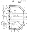
- Fig. 1 shows in section the floor plan of one half of a portable, prefabricated sanitary cell, which is octagonal in this embodiment.
- the sanitary cell preferably consists of prefabricated concrete parts, which however are assembled in the factory and provided with the sanitary and auxiliary equipment.
- the sanitary cell can also have other floor plans and can be combined with other sanitary cells.
- Each sanitary cell has a central installation space 10 with a wall 11 which forms an installation wall.
- the sanitary cell has a peripheral wall 12 and at least one partition 13 with a door 14.
- In the peripheral wall 12 there is an entrance door 15 which leads from the outside into the useful space 16.
- the usable space 16 has the partition wall 13 in order to separate a toilet room.
- the wall 11 is located between the installation space 10 and the useful space 16, the sanitary cell shown in FIG. 1 having two useful spaces 16, which are separated from one another by the installation space 10, which is also provided with a passage door (not shown) in the peripheral wall 12.
- the wall 11 is provided with openings 17 which have mounting rails 18 and are provided with a frame profile 19.
- a toilet bowl 20, a sink 30 and two urinal bowls 40 are provided as sanitary devices.
- the devices are shown on the left outside the wall and on the right in the state mounted inside the wall 11.
- the direction of insertion from the installation space 10 is illustrated by arrows.
- a hand wash corner 50 according to FIG. 9, 10 can be provided, which is embedded in the wall 11 in such a way that it only projects in the direction of the installation space 10.
- All devices have a housing 21, 31, 41, 51 which is closed except for the functional opening in the direction of the useful space 16 and a rear side 22, 32, 42, 52 which is essentially open in the direction of the installation space 10.
- a mounting frame 23, 33, 43, 53 which is optionally connected to the mounting rails 18 via lugs 63 by means of screw bolts 68. All of these elements can only be reached from the installation space 10.
- the housing 21, 31, 41, 51 in the illustrated exemplary embodiments is a hollow construction made of stainless steel sheet, preferably stainless steel sheet, and has a flange 29, 39, 49, 59 that surrounds the open rear side 22, 32, 42, 52 Frame profile 19 of each opening 17 is precisely adapted or can be inserted into this.
- a sealing tape can be provided between the flange 29, 39, 49, 59 and the frame profile 19.
- the sealing tape can be a plastic profile, which forms an end strip on the surface of the wall 11 facing the usable space 16.
- a rim 67 made of metal, plastic or the like can be placed on the edge of the opening 17 on the surface of the wall 11 facing the usable space 16. be assigned.
- the flushing rim 24 surrounding the functional opening has a narrow circumferential water outlet slot 25 which enables nozzle-like water acceleration but does not form an undercut within the functional opening. This largely eliminates the risk of deposits and also eliminates the risk of injury.
- the seat 26 enclosing the functional opening can be slightly inclined in the direction of the free end of the housing 21. In the center of the functional opening there is an outlet 27 which, like the water inlet 28 to the rinsing rim 24, can be easily reached from the open rear side 21 or the installation space 10 in order to connect supply and disposal lines or to carry out any maintenance work.
- the wash basin 30 according to FIGS. 5, 6 also has one pointing towards the functional space 16 except for the functional opening closed housing 31 with an open rear side 32 in the direction of the installation space 10, through which a drain line 34 extends.
- a wall part 35 pointing in the direction of the bottom of the useful space 16 is provided with an opening 36 which is closed by a cover 37 .
- the wing nut 66 can only be reached from the installation space 10, so that a hose can be drawn from the installation space 10 into the useful space 16 through the rear side 32 and the opening 36, in order to clean and disinfect it.
- the cover 37 is not adjustable from the usable space 16.
- a water drain 44 and a water inlet 45 are provided in the functional opening. Both can only be operated and serviced from the installation space 10 through the open rear side 42.
- the housing 51 protrudes through the wall 11 into the installation space 10, so that the surface of the wall 11 pointing into the useful space 16 is smooth.
- the housing 51 has a water outlet 54 and a water inlet 55.
- a cover 58 which is made in one piece from the stainless steel with the housing 51 and behind which there is a warm air blower 60 is located, which has a pressure connection 61 which is open in the direction of the opening 57 in order to conduct warm air into the interior of the housing 51 for drying the hands if necessary.
- the cover 50 carries a switch 62 for the hot air blower 60, the switch 62 as the pressure switch, proximity switch, light switch or the like. can be trained.
- switches can also be provided, which are triggered by the users. So the doors 14 and / or 15 can be provided with door switches in the door sill. Proximity switches can be arranged in the wall 11, which are also initially to be activated by a door switch.
- the installation space 10 need not - as described above - to be provided with a passage door in the peripheral wall 12, but can have a door-like section in the wall 11 which can be pivoted outwards in the direction of the useful space 16 and with at least one opening 17 for a sanitary or auxiliary device 20, 30, 40, 50 is provided.
- Auxiliary devices are lighting fixtures, ventilation fans, soap dispensers, paper dispensers and the like, which are embedded in the wall 11, but are not shown in detail.
- a skylight 64 can be arranged in the ceiling 65 of the sanitary cell and, if appropriate, can also serve for ventilation.
- the mounting rails 18 can also have elongated holes, which allow easier fitting of the sanitary and auxiliary devices 20, 30, 40, 50 into the openings 17.
- a warm air heater can be provided to heat the utility room 16, which blows warm air from the installation room 10 into the utility room 16.
- the bottom 71 of the housing 21 of the toilet Basin 20 expediently provided with an air outlet opening 70.
- the warm air can then be blown through the open back 22 of the toilet bowl 20 from the installation space 10 into the interior of the housing 21, from where the heated air passes through the outlet opening 70 into the useful space 16.
- a tube or hose line 69 is provided, the free end of which is pushed onto a flange 72 and fastened thereon by means of a clamp 73.
- the flange 72 surrounds the air outlet opening 70.
- the sanitary cell is provided with an automatic cleaning device which has the following structure.
- a lower ceiling 75 is provided above the useful space 16, which has an opening 46 for each of the useful spaces 16.
- the opening 46 is closed by a cover 74 which is arranged at the free end of a telescopic arm 76 which can be extended through the opening 46 into the useful space 16.
- a boom 79 is articulated to the cover 74 and can be pivoted by a working cylinder 80.
- a spraying element 77 and a blowing element 78 At the free end of the boom 79 there is a spraying element 77 and a blowing element 78.
- the spraying element 77 is fed with water by a pump 87 via a hose 47.
- the blower organ 78 is supplied with compressed air by a compressor 88 via a hose 48.
- lines 81, 82 lead to reels 83, 84 from the pump 87 and the compressor 88.
- the hoses 47 and 48 are guided over rollers 85 in the area of the ceilings 65 and 75. This way they keep Springs in the reels 83 and 84 always hold the hoses 47 and 48 under tension, regardless of how far the telescopic arm 76 is extended.
- a control unit 90 is provided in the installation space 10, which controls a servomotor 91, the telescopic arm 76 and the working cylinder 80 via lines 89.
- the servomotor 91 is arranged on the ceiling 65 and a cantilever arm 93 is attached to the free end of its shaft 92.
- the telescopic arm 76 is arranged at the free end of the cantilever arm 93.
- the geometry of the cover 74 and the boom 79 articulated on this is designed such that the working cylinder 80 can pivot the boom 79 to such an extent that in the rest position above the cover 74 it fits into the space between the ceilings 65 and 75.
- the usable space 16 is then again provided with a continuous ceiling 75.
- the control unit 90 can deliver electrical, pneumatic and / or hydraulic control signals via the lines 89.
- the telescopic arm 76 and the working cylinder 80 expediently work with a pneumatic fluid.
- the control unit 90 which also controls the water pump 87 and the air compressor 88, is freely programmable.
- the cleaning program for the walls of the utility room 16 and the sanitary appliances 20, 30, 40 and 50 can be constructed in such a way that the toilet bowl 20 and the urinal bowl 40 after each use, the hand wash basin 30 after every fifth use, the floor of the utility room 16 after every seventh use and the entire wall area of the utility room 16 are cleaned at night.
- a separate twilight switch can be provided for night cleaning.
- the control unit 90 is triggered, for example, by switches (not shown) integrated in the threshold of the doors 15.
- Optical actuators can also be provided to control the control unit 90, which trigger the individual operating phases.
- a fixed cleaning program can be provided for 24 hours, which can be influenced as required.
- water is first sprinkled onto the areas to be cleaned by the spraying element 77, the water also being able to be heated.
- Detergent and / or disinfectant can be added to the water in the area of the pump 87 or at another location.
- the blowing element 78 is acted upon, which optionally dries the cleaned devices or wall areas of the usable space 16 with warm air.
- a rotary head 86 is provided at the free end of the cantilever arm 93, the rotary head 86 also being able to be raised and lowered in order to insert the cover 74, which can also be round, into the opening 46.
- the turret 86 preferably moves the entire telescopic arm 76 about its own axis.
- the cleaning device serves two useful rooms 16. However, a larger number of useful rooms can also be reached if these are provided.
Abstract
Description
Die Erfindung betrifft eine transportable, vorgefertigte Sanitärzelle der im Oberbegriff von Anspruch 1 näher erläuterten Art.The invention relates to a transportable, prefabricated sanitary cell of the type explained in more detail in the preamble of claim 1.
Bei einer bekannten Sanitärzelle dieser Art ist im Zentrum der im Grundriß quadratischen Zelle ein Installationsraum vorgesehen, an dessen Wandungen von außen her die sanitären Geräte, wie Waschbecken, WC-Becken, Urinale od.dgl. befestigt sind. Eine der Wandungen des engen Installationsraums ist nach außen ---wegschwenkbar, so daß die Ver- und Entsorgungsleitungen vom Installationsraum her an die sanitären Geräte angeschlossen werden können. Die Wandungen der bekannten Sanitärzelle haben demgemäß zahlreiche Unterbrechungen, und die Ver- und Entsorgungsleitungen müssen mindestens im Bereich der wegschenkbaren Wandung flexibel ausgebildet werden. Neben dem zusätzlichen konstruktiven Aufwand und der Montage von innen und außen lassen sich die sanitären und Hilfsgeräte nur unter größeren Schwierigkeiten warten, weil der Installationsraum nicht begehbar ist.In a known sanitary cell of this type, an installation space is provided in the center of the square cell in plan, on the walls of which the sanitary appliances, such as wash basins, toilet bowls, urinals or the like, are on the outside. are attached. One of the walls of the narrow installation room can be swung outwards so that the supply and disposal lines can be connected to the sanitary devices from the installation room. The walls of the known sanitary cell accordingly have numerous interruptions, and the supply and disposal lines must be designed to be flexible, at least in the area of the pivotable wall. In addition to the additional design effort and installation from the inside and outside, the sanitary and auxiliary devices can only be serviced with great difficulty because the installation space is not accessible.
Demgegenüber ist es Aufgabe der vorliegenden Erfindung, bei einer derartigen Sanitärzelle die Montage der sanitären und gegebenenfalls Hilfsgeräte zu vereinfachen, ohne daß Anschlußelemente vom Nutzraum aus -zugänglich sind.In contrast, it is an object of the present invention to simplify the assembly of the sanitary and, if necessary, auxiliary devices in such a sanitary cell without connecting elements being accessible from the usable space.
Zur Lösung dieser Aufgabe werden erfindungsgemäß die kennzeichnenden Merkmale von Anspruch 1 vorgeschlagen.To achieve this object, the characterizing features of claim 1 are proposed according to the invention.
Hierdurch wird der Vorteil erreicht, daß der Installationsraum feststehende, durchgehende Wandungen aufweist, die nur mit den Unterbrechungen versehen sind, die zur Anbringung-der sanitären Geräte und gegebenenfalls von Hilfsgeräten erforderlich sind. Die Montage erfolgt ausschließlich vom Installationsraum-her und auch alle Anschlüsse der Ver- und Entsorgungsleitungen sind vom Installationsraum her zu erreichen und zwar nicht nur für die Montage, sondern auch bei späteren Wartungsarbeiten. Dadurch erübrigt sich, beim Auswechseln einzelner sanitärer Geräte die gesamte Sanitärzelle außer Betrieb zu setzen. Von dem Nutzraum her sind keinerlei Anschlußelemente zur Montage der sanitären und Hilfsgeräte sowie der Ver-und Entsorgungsleitungen sichtbar bzw. erreichbar. Andererseits sind auch die Innenräume der einzelnen Geräte von dem Installationsraum her bequem zugänglich. So brauchen die Geräte nicht mit Rückwänden versehen zu sein, was sich auch bei etwaigen Wartungsarbeiten an elektrischen Geräten als nützlich erweist. Papier- und Seifenspender werden vom Installationsraum her beschickt, so daß vom Nutzraum her lediglich die Entnahmeöffnungen zugänglich sind. Die Böden sowohl des Installationsraums als auch der Nutzräume sind frei von Einbauten, was die Reinigung erleichtert. Zapf- und Spülimpulse werden vorzugsweise berührungsfrei ausgelöst. Die von den Benutzern zugänglichen Räume haben insbesondere glatte-durchgehende Wände ohne herausstehende Armaturen und durch das vollständige bzw. mindestens teilsweise Einlassen der sanitären und Hilfsgeräte in die Wandung des Installationsraums kragen nur solche Teile der sanitären und Hilfsgeräte in den Nutzraum, die für eine bestimmungsgemäße Benutzung erforderlich sind.This has the advantage that the installation space has fixed, continuous walls which are only provided with the interruptions which are necessary for the attachment of the sanitary devices and, if appropriate, of auxiliary devices. The assembly is carried out exclusively by the I-nstallationsraum ago and all connections the supply and disposal lines can be reached from the installation room and not only for assembly, but also for later maintenance work. This eliminates the need to shut down the entire bathroom when replacing individual sanitary devices. No connection elements for mounting the sanitary and auxiliary devices as well as the supply and disposal lines are visible or accessible from the usable space. On the other hand, the interiors of the individual devices are easily accessible from the installation room. This means that the devices do not have to be provided with rear walls, which also proves useful for any maintenance work on electrical devices. Paper and soap dispensers are loaded from the installation room, so that only the removal openings are accessible from the utility room. The floors of both the installation room and the utility rooms are free of fittings, which makes cleaning easier. Tapping and flushing pulses are preferably triggered without contact. The rooms accessible by the users have, in particular, smooth, continuous walls without protruding fittings and due to the complete or at least partial insertion of the sanitary and auxiliary devices into the wall of the installation space, only those parts of the sanitary and auxiliary devices protrude into the usable space that are intended for the intended use required are.
Vorteilhafte Ausgestaltungen der Erfindung sind in den Unteransprüchen unter Schutz gestellt.Advantageous embodiments of the invention are protected in the subclaims.
In der Zeichnung sind Ausführungsbeispiele der Erfindung wiedergegeben, die anhand der nachfolgenden Beschreibung näher erläutert werden. Es zeigt:
- Fig. 1 die Hälfte einer Sanitärzelle im Grundriß,
- Fig. 2 einen Schnitt gemäß Linie II - II in Fig. 1,
- Fig. 3 einen Schnitt durch ein WC-Becken gemäß Linie III - III in Fig. 1 im vergrößerten Maßstab,
- Fig. 4 eine Draufsicht auf das WC-Becken gemäß Fig. 3,
- Fig. 5 einen Schnitt durch ein Waschbecken gemäß Linie V - V in Fig. 1 im vergrößerten Maßstab,
- Fig. 6 eine Draufsicht auf das Waschbecken gemäß Fig. 5,
- Fig. 7 einen Schnitt durch ein Urinalbecken gemäß Linie VII - VII in Fig. 1,
- Fig. 8 eine Ansicht des Urinalbeckens gemäß Fig. 7,
- Fig. 9 einen Querschnitt durch ein Handwaschbecken,
- Fig. 10 eine Seitenansicht des Handwaschbeckens gemäß Fig. 9,
- Fig. 11 ein weiteres Ausführungsbespiel der Sanitärzelle im Grundriß und
- Fig. 12 einen Schnitt gemäß Linie XII - XII in Fig. 11.
- 1 half of a sanitary cell in plan,
- 2 shows a section along line II-II in FIG. 1,
- F ig. 3 shows a section through a toilet bowl along line III-III in FIG. 1 on an enlarged scale,
- 4 shows a plan view of the toilet bowl according to FIG. 3,
- 5 shows a section through a wash basin according to line V - V in FIG. 1 on an enlarged scale,
- 6 is a plan view of the sink according to FIG. 5,
- 7 shows a section through a urinal basin according to line VII-VII in FIG. 1,
- F ig. 8 is a view of the urinal basin according to FIG. 7,
- 9 shows a cross section through a hand wash basin,
- 10 is a side view of the hand basin according to FIG. 9,
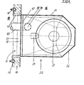
- Fig. 11 shows another example of execution of the sanitary cell in plan and
- 12 shows a section along line XII-XII in FIG. 11.
Fig. 1 zeigt im Schnitt den Grundriß einer Hälfte einer transportablen, vorgefertigten Sanitärzelle, die bei diesem Ausführungsbeispiel achteckig ist. Die Sanitärzelle besteht vorzugsweise aus Fertigbetonteilen, die jedoch fabrikmäßig zusammengesetzt und mit den sanitären und Hilfsgeräten versehen werden Rönnen. Die Sanitärzelle kann auch andere Grundrisse aufweisen und mit weiteren Sanitärzellen kombiniert werden.Fig. 1 shows in section the floor plan of one half of a portable, prefabricated sanitary cell, which is octagonal in this embodiment. The sanitary cell preferably consists of prefabricated concrete parts, which however are assembled in the factory and provided with the sanitary and auxiliary equipment. The sanitary cell can also have other floor plans and can be combined with other sanitary cells.
Jede Sanitärzelle hat einen zentralen Installationsraum 10 mit einer Wandung 11, die eine Installationswand bildet. Außerdem hat die Sanitärzelle eine Umfangswand 12 und mindestens eine Trennwand 13 mit einer Tür 14. In der Umfangswand 12 befindet sich eine Eingangstür 15, die von außen in den Nutzraum 16 führt. Der Nutzraum 16 weist die Trennwand 13 auf, um einen WC-Raum abzutrennen. Zwischen dem Installationsraum 10 und dem Nutzraum 16 befindet sich die Wandung 11, wobei die in Fig. 1 dargestellte Sanitärzelle zwei Nutzräume 16 hat, die durch den Installationsraum 10 voneinander getrennt sind, der ebenfalls mit einer nicht dargestellten Durchgangstür in der Umfangswand 12 versehen ist.Each sanitary cell has a
Die Wandung 11 ist mit Durchbrechungen 17 versehen, die Montageschienen 18 aufweisen und mit einem Rahmenprofil 19 versehen sind.The
Als sanitäre Geräte sind gemäß Fig. 1 ein WC-Becken 20, ein Waschbecken 30 und zwei Urinalbecken 40 vorgesehen. Bei diesem Ausführungsbeispiel gemäß Fig. 1 sind die Geräte links außerhalb der Wandung dargestellt und rechts im innerhalb der Wandung 11 montierten Zustand gezeigt. Die Einschubrichtung vom Installationsraum 10 her ist durch Pfeile verdeutlicht.1, a
Zusätzlich zu den in Fig. 1 dargestellten Geräten bzw. alternativ zu dem Waschbecken 30 kann ein Handwaschecken 50 gemäß Fig. 9,10 vorgesehen sein, das in die Wandung 11 in der Weise eingelassen ist, daß es nur in Richtung des Installationsraums 10 vorspringt.In addition to the devices shown in FIG. 1 or alternatively to the
Alle Geräte haben ein bis auf die Funktionsöffnung in Richtung des Nutzraums 16 geschlossenes Gehäuse 21, 31, 41,51 und eine in Richtung des Installationsraums 10 im wesentlichen offene Rückseite 22,32,42,52. Im Bereich der Rückseite 22,32,42,52 befindet sich ein Montagerahmen 23, 33,43,53, der gegebenenfalls über Knaggen 63 mittels Schraubbolzen 68 an die Montageschienen 18 angeschlossen ist. Alle diese Elemente sind nur vom Installationsraum 10 her erreichbar. Das Gehäuse 21,31,41,51 ist bei den dargestellten Ausführungsbeispielen eine Hohlkonstruktion aus nicht-rostendem Stahlblech, vorzugsweise Edelstahlblech, und hat einen die offene Rückseite 22,32,42,52 umschließenden Flansch 29,39, 49,59,der dem Rahmenprofil 19 einer jeden Durchbrechung 17 genau angepaßt bzw. in dieses hinein-steckbar ist. Zwischen dem Flansch 29, 39,49,59 und dem Rahmenprofil 19, kann ein nicht dargestelltes Dichtungsband vorgesehen sein. Das Dichtungsband kann ein Kunststoff-Profil sein, das auf der in den Nutzraum 16 weisenden Oberfläche der Wandung 11 eine Abschlußleiste bildet. Dem Rand der Durchbrechung 17 kann auf der in den Nutzraum 16 weisenden Oberfläche der Wandung 11 eine Blende 67 aus Metall, Kunststoff od.dgl. zugeordnet sein.All devices have a
Bei dem in Fig. 3 und 4 dargestellten WC-Becken 20 hat der die Funktionsöffnung umschließende Spülrand 24 einen engen umlaufenden Wasser-Austrittsschlitz 25, der eine düsenartige Wasserbeschleunigung ermöglicht, jedoch keine Hinterschneidung innerhalb der Funktionsöffnung bildet. Dadurch ist die Gefahr von Ablagerungen weitgehend ausgeschaltet und auch eine Verletzungsgefahr eliminiert. Die die Funktionsöffnung umschließende Sitzfläche 26 kann in Richtung des freien Endes des Gehäuses 21 etwas geneigt sein. Im Zentrum der Funktionsöffnung befindet sich ein Ablauf 27, der ebenso wie der Wasserzulauf 28 zu dem Spülrand 24 von der offenen Rückseite 21 bzw. dem Installationsraum 10 her ohne weiteres erreichbar ist, um Ver- und Entsorgungsleitungen anzuschließen oder etwaige Wartungsarbeiten auszuführen.In the
Das Waschbecken 30 gemäß Fig. 5,6 hat ebenfalls ein bis auf die Funktionsöffnung in Richtung des Nutzraums 16 weisend geschlossenes Gehäuse 31 mit einer in Richtung des Installationsraums 10 offenen Rückseite 32, durch die sich eine Ablaufleitung 34 hindurch erstreckt. Ein in Richtung des Bodens des Nutzraums 16 weisender Wandteil 35 ist mit einer Öffnung 36 versehen, die durch einen Deckel 37.verschließbar ist, der in Führungen 38 gleitend verstellbar und durch ein Sicherungselement, wie eine Flügelmutter/ Schraube 66, in der Schließstellung fixierbar ist. Die Flügelmutter 66 ist lediglich von dem Installationsraum 10 her erreichbar, so daß durch die Rückseite 32 und die Öffnung 36 ein Schlauch von dem Installationsraum 10 her in den Nutzraum 16 gezogen werden kann, um diesen zu reinigen und gegebenenfalls zu desinfizieren. Der Deckel 37 ist vom Nutzraum 16 aus nicht verstellbar.The
Bei dem Urinalbecken 40 gemäß Fig. 7 und 8 sind in der Funktionsöffnung ein Wasserablauf 44 und ein Wasserzulauf 45 vorgesehen. Beide sind durch die offene Rückseite 42 nur vom Installationsraum 10 her zu bedienen und zu warten.7 and 8, a
Bei dem in Fig. 9 und 10 dargestellten Handwaschbecken 50 ragt das Gehäuse 51 durch die Wandung 11 hindurch lediglict in den Installationsraum 10, so daß die in den Nutzraum 16 weisende Oberfläche der Wandung 11 glatt ist. Das Gehäuse 51 weist einen Wasserablauf 54 und einen Wasserzulauf 55 auf. In der nach oben weisenden Wand 56 des Gehäuses 51 befindet sich eine Durchbrechung 57, und mit der in Richtun des Nutzraums 16 weisenden Oberfläche der Wandung 11 fluch eine Abdeckung 58, die mit dem Gehäuse 51 einstückig aus Edelstahl gefertigt ist und hinter der sich ein Warmluftgebläse 60 befindet, das einen Druckstutzen 61 hat, der in Richtung der Durchbrechung 57 offen ist, um bei Bedarf Warmluft zum Trocknen der Hände in den Innenraum des Gehäuses 51 zu leiten. Die Abdeckung 50 trägt einen Schalter 62 für das Warmluftgebläse 60, wobei der Schalter 62 als Druckschalter, Annäherungsschalter, Lichtschalter od.dgl. ausgebildet sein kann.In the
Weitere nicht dargestellte Schalter können ebenfalls vorgesehen sein, die durch die Benutzer ausgelöst werden. So können die Türen 14 und/oder 15 mit Türschaltern in der Türschwelle versehen sein. In der Wandung 11 können Annäherungsschalter angeordnet werden, die ebenfalls zunächst durch einen Türschalter zu aktivieren sind.Further switches, not shown, can also be provided, which are triggered by the users. So the
Der Installationsraum 10 braucht nicht - wie oben beschrieben - mit einer Durchgangstür in der Umfangswand 12 versehen zu sein, sondern kann einen türartigen Abschnitt in der Wandung 11 aufweisen, der nach außen in Richtung des Nutzraums 16 schwenkbar und mit mindestens einer Durchbrechung 17 für ein sanitäres oder Hilfsgerät 20,30,40,50 versehen ist. Hilfsgeräte sind Beleuchtungskörper, Belüftungsgebläse, Seifenspender, Papierspender u.dgl., die in die Wandung 11 eingelassen, jedoch im einzelnen nicht dargestellt sind. Ein Oberlicht 64 kann in der Decke 65 der Sanitärzelle angeordnet sein und gegebenenfalls gleichzeitig der Belüftung dienen.The
Als Schraubbolzen 68 können Hammerkopfschrauben und übliche Sechskantmuttern Anwendung finden. Die Montageschienen 18 können auch Langlöcher aufweisen, die ein leichteres Einpassen der sanitären und Hilfsgeräte 20, 30,40,50 in die Durchbrechungen 17 gestatten.Hammer head screws and conventional hexagon nuts can be used as
Zur Beheizung des Nutzraums 16 kann eine Warmluftheizung vorgesehen sein, die Warmluft aus dem Installationsraum 10 in den Nutzraum 16 bläst. Um diesmöglichst strörungsfrei zu machen, ist der Boden 71 des Gehäuses 21 des WC-Beckens 20 zweckmäßigerweise mit einer Luftaustrittsöffnung 70 versehen. Die Wärmluft kann dann durch die offene Rückseite 22 des WC-Beckens 20 vom Installationsraum 10 aus in den Innenraum des Gehäuses 21 geblasen werden, von wo aus die erwärmte Luft durch die Austrittsöffnung 70 in den Nutzraum 16 gelangt. Bei dem Ausführungsbeispiel gemäß Fig. 3 ist eiIeRohr- oder Schlauchleitung 69 vorgesehen, deren freies Ende auf einen Flansch 72 aufgeschoben und auf diesem mittels einer Schelle 73 befestigt ist. Der Flansch 72 umschließt die Luftaustrittsöffnung 70. Diese Anordnung hat den Vorteil, daß zwar das WC-Becken 20 etwas, jedoch nicht zu stark erwärmt wird.A warm air heater can be provided to heat the
Bei dem Ausführungsbeispiel gemäß Fig. 11 und 12 ist die Sanitärzelle mit einen selbsttätigen Reinigungsgerät versehen, das folgenden Aufbau hat. Unterhalb der Decke 65 und unter Abstand von dieser ist oberhalb des Nutzraums 16 eine Unterdecke 75 vorgesehen, die eine Öffnung 46 für jeden der Nutzräume 16 aufweist. In der Ruhestellung des Reinigungsgeräts ist die Öffnung 46 durch einen Deckel 74 verschlossen, der an dem freien Ende eines Teleskoparms 76 angeordnet ist, der durch die Öffnung 46 hindurch in den Nutzraum 16 hinein ausfahrbar ist. An den Deckel 74 ist ein Ausleger 79 angelenkt, der durch einen Arbeitszylinder 80 verschwenkbar ist. An dem freien Ende des Auslegers 79 befindet sich ein Sprühorgan 77 und ein Blasorgan 78. Das Sprühorgan 77 wird von einer Pumpe 87 aus über einen Schlauch 47 mit Wasser gespeist. Das Blasorgan 78 wird von einem Kompressor 88 über einen Schlauch 48 mit Druckluft versorgt. Zu diesem Zweck führen von der Pumpe 87 und dem Kompressor 88 Leitungen 81,82 zu Haspeln 83,84. Die Schläuche 47 und 48 sind über Rollen 85 im Bereich der Decken 65 und 75 geführt. Auf diese Weise halten die Federn in den Haspeln 83 und 84 die Schläuche 47 und 48 stets gespannt, unabhängig davon, wie weit der Teleskoparm 76 ausgefahren wird.In the exemplary embodiment according to FIGS. 11 and 12, the sanitary cell is provided with an automatic cleaning device which has the following structure. Below the
Außerdem ist in dem Installationsraum 10 eine Steuereinheit 90 vorgesehen, die über Leitungen 89 einen Stellmotor 91, den Teleskoparm 76 und den Arbeitszylinder 80 steuert. Der Stellmotor 91 ist an der Decke 65 angeordnet und an dem freien Ende seiner Welle 92 ist ein Kragarm 93 befestigt. An dem freien Ende des Kragarms93 ist der Teleskoparm 76 angeordnet.In addition, a
Die Geometrie des Deckels 74 und des an diesem angelenkten Auslegers 79 ist derart ausgelegt, daß der Arbeitszylinder 80 den Ausleger 79 derart weit verschwenken kann, daß er in der Ruhestellung oberhalb des Deckels 74 in den Raum zwischen den Decken 65 und 75 paßt. Der Nutzraum 16 ist dann wieder mit einer durchgehenden Decke 75 versehen.The geometry of the
Die Steuereinheit 90 kann über die Leitungen 89 elektrische, pneumatische und/oder hydraulische Steuersignale liefern. Der Teleskoparm 76 und der Arbeitszylinder 80 arbeiten zweckmäßigerweise mit einem pneumatischen Strömungsmittel.The
Die Steuereinheit 90, die auch die Wasserpumpe 87 und den Luftkompressor 88 steuert, ist frei programmierbar. Das Reinigungsprogramm für die Wände des Nutzraums 16 und der sanitären Geräte 20,30,40 und 50 kann derart aufgebaut sein, daß das WC-Becken 20 und das Urinalbecken 40 nach jeder Benutzung, das Handwaschbecken 30 nach jeder fünften Benutzung, der Fußboden des Nutzraums 16 nach jeder siebten Benutzung und der gesamte Wandbereich des Nutzraums 16 in der Nacht gereinigt werden. Für die Nachtreinigung kann ein gesonderter Dämmerungsschalter vorgesehen sein. Im übrigen wird die Steuereinheit 90 beispielsweise durch nicht dargestellte in die Schwelle der Türen 15 integrierte Schalter ausgelöst., Zur Ansteuerung der Steuereinheit 90 können auch optische Fühler vorgesehen sein, die die einzelnen Betriebsphasen auslösen. Es kann ein festes Reinigungsprogramm über 24 Stunden vorgesehen sein, das bedarfsabhängig beeinflußbar ist.The
Bei den meisten Reinigungsphasen wird zunächst von dem Sprühorgan 77 Wasser auf die zu reinigenden Stellen gesprengt, wobei das Wasser auch erwärmt werden kann. Im Bereich der Pumpe 87 oder an einer anderen Stelle kann dem Wasser Reinigungs- und/oder Desinfektionsmittel zudosiert werden. Nach dem Ablauf des Wasser-Reinigungsprogramms, wobei überschüssiges Wasser durch eine Rinne 94 abfließen kann, wird das Blasorgan 78 beaufschlagt, das gegebenenfalls mit Warmluft die gereinigten Geräte oder Wandbereiche des Nutzraums 16 trocknet.In most cleaning phases, water is first sprinkled onto the areas to be cleaned by the spraying element 77, the water also being able to be heated. Detergent and / or disinfectant can be added to the water in the area of the
Um den Ausleger 79 zu verschwenken, ist ein Drehkopf 86 am freien Ende des Kragarms 93 vorgesehen, wobei der Drehkopf 86 auch heb- und senkbar ist, um den Deckel 74, der auch rund sein kann, in die Öffnung 46 einzuführen. Der Drehkopf 86 verstellt vorzugsweise den gesamten Teleskopfarm 76 um seine eigene Achse.In order to pivot the
Gemäß Fig. 11 bedient das Reinigungsgerät zwei Nutzräume 16. Es kann jedoch auch eine größere Anzahl von Nutzräumen erreichen, sofern diese vorgesehen sind.According to FIG. 11, the cleaning device serves two
Claims (16)
Priority Applications (1)
| Application Number | Priority Date | Filing Date | Title |
|---|---|---|---|
| AT85105869T ATE29958T1 (en) | 1984-05-25 | 1985-05-13 | SANITARY CELL. |
Applications Claiming Priority (2)
| Application Number | Priority Date | Filing Date | Title |
|---|---|---|---|
| DE19843419630 DE3419630A1 (en) | 1984-05-25 | 1984-05-25 | SANITARY CELL |
| DE3419630 | 1984-05-25 |
Publications (3)
| Publication Number | Publication Date |
|---|---|
| EP0162397A2 true EP0162397A2 (en) | 1985-11-27 |
| EP0162397A3 EP0162397A3 (en) | 1986-01-08 |
| EP0162397B1 EP0162397B1 (en) | 1987-09-30 |
Family
ID=6236901
Family Applications (1)
| Application Number | Title | Priority Date | Filing Date |
|---|---|---|---|
| EP85105869A Expired EP0162397B1 (en) | 1984-05-25 | 1985-05-13 | Sanitary cell |
Country Status (3)
| Country | Link |
|---|---|
| EP (1) | EP0162397B1 (en) |
| AT (1) | ATE29958T1 (en) |
| DE (2) | DE3419630A1 (en) |
Cited By (5)
| Publication number | Priority date | Publication date | Assignee | Title |
|---|---|---|---|---|
| EP0356691A1 (en) * | 1988-08-06 | 1990-03-07 | Hans Wall | Sanitary compartment for public use |
| EP0489187A1 (en) * | 1989-07-21 | 1992-06-10 | Gebr. OTTO KG | Sanitary appliance |
| FR2702788A1 (en) * | 1993-03-18 | 1994-09-23 | Fontaine Ernest | Self-cleaning toilet seat. |
| US9060652B2 (en) * | 2013-03-15 | 2015-06-23 | Marcel Adriaan Dirk Bikker | Transportable sanitary unit |
| US11255097B2 (en) | 2017-12-14 | 2022-02-22 | Mad Investments Bv | Transportable sanitary unit |
Citations (4)
| Publication number | Priority date | Publication date | Assignee | Title |
|---|---|---|---|---|
| FR2199780A5 (en) * | 1972-05-31 | 1974-04-12 | Tissandier Paul | |
| DE8018723U1 (en) * | 1980-07-10 | 1981-01-08 | Huster, Frank, 7441 Neckartenzlingen | KIT FOR SANITARY CELLS |
| FR2482852A1 (en) * | 1980-05-23 | 1981-11-27 | Decaux Jean Claude | Self-cleaning micro-processor controlled lavatory unit - has rotatable lavatory compartments enclosing compartment housing cleaning device for lavatory pan and compartment walls |
| DE3138001A1 (en) * | 1981-09-24 | 1983-05-11 | Karlheinz 6522 Osthofen Scriba | Energy column |
-
1984
- 1984-05-25 DE DE19843419630 patent/DE3419630A1/en not_active Withdrawn
-
1985
- 1985-05-13 DE DE8585105869T patent/DE3560693D1/en not_active Expired
- 1985-05-13 AT AT85105869T patent/ATE29958T1/en not_active IP Right Cessation
- 1985-05-13 EP EP85105869A patent/EP0162397B1/en not_active Expired
Patent Citations (4)
| Publication number | Priority date | Publication date | Assignee | Title |
|---|---|---|---|---|
| FR2199780A5 (en) * | 1972-05-31 | 1974-04-12 | Tissandier Paul | |
| FR2482852A1 (en) * | 1980-05-23 | 1981-11-27 | Decaux Jean Claude | Self-cleaning micro-processor controlled lavatory unit - has rotatable lavatory compartments enclosing compartment housing cleaning device for lavatory pan and compartment walls |
| DE8018723U1 (en) * | 1980-07-10 | 1981-01-08 | Huster, Frank, 7441 Neckartenzlingen | KIT FOR SANITARY CELLS |
| DE3138001A1 (en) * | 1981-09-24 | 1983-05-11 | Karlheinz 6522 Osthofen Scriba | Energy column |
Cited By (9)
| Publication number | Priority date | Publication date | Assignee | Title |
|---|---|---|---|---|
| EP0356691A1 (en) * | 1988-08-06 | 1990-03-07 | Hans Wall | Sanitary compartment for public use |
| EP0489187A1 (en) * | 1989-07-21 | 1992-06-10 | Gebr. OTTO KG | Sanitary appliance |
| FR2702788A1 (en) * | 1993-03-18 | 1994-09-23 | Fontaine Ernest | Self-cleaning toilet seat. |
| WO1994021866A2 (en) * | 1993-03-18 | 1994-09-29 | Ernest Fontaine | Self-cleaning toilet |
| WO1994021866A3 (en) * | 1993-03-18 | 1994-11-10 | Ernest Fontaine | Self-cleaning toilet |
| US9060652B2 (en) * | 2013-03-15 | 2015-06-23 | Marcel Adriaan Dirk Bikker | Transportable sanitary unit |
| US9366019B2 (en) | 2013-03-15 | 2016-06-14 | Marcel Adriaan Dirk Bikker | Transportable sanitary unit |
| US9605424B2 (en) | 2013-03-15 | 2017-03-28 | Marcel Adriaan Dirk Bikker | Transportable sanitary unit |
| US11255097B2 (en) | 2017-12-14 | 2022-02-22 | Mad Investments Bv | Transportable sanitary unit |
Also Published As
| Publication number | Publication date |
|---|---|
| EP0162397B1 (en) | 1987-09-30 |
| EP0162397A3 (en) | 1986-01-08 |
| DE3560693D1 (en) | 1987-11-05 |
| ATE29958T1 (en) | 1987-10-15 |
| DE3419630A1 (en) | 1985-11-28 |
Similar Documents
| Publication | Publication Date | Title |
|---|---|---|
| EP0301070B1 (en) | Public toilet cubicle | |
| EP1491693B1 (en) | Water-closet | |
| EP2071087A2 (en) | Self-cleaning toilet | |
| EP2531661A1 (en) | Technical unit for a sanitary fixture | |
| DE4221508A1 (en) | Sanitary cell with high pressure cleaning - has at least one sanitary room and at least one technical room and contains carousel type, rotatable, rotation symmetrical structural unit. | |
| DE60221943T2 (en) | Improved automatic device for washing a toilet seat | |
| EP2374947B1 (en) | Sanitary module mit sanitary appliances, sanitary room with the sanitary module and method of cleaning automatically the sanitary appliances | |
| DE19720762C2 (en) | Sanitary cell with sanitary and technical room as well as procedures for cleaning and / or disinfecting the sanitary room | |
| EP0517131A1 (en) | Sanitary unit with automatic cleaning device for the toilet bowl | |
| EP0356691B1 (en) | Sanitary compartment for public use | |
| EP0162397B1 (en) | Sanitary cell | |
| EP0467828B1 (en) | Urinal suspended from a wall | |
| EP0517132A1 (en) | Sanitary unit with automatic seat-cleaning device | |
| DE3631748A1 (en) | Urinal | |
| DE2725406A1 (en) | Toilet for rest areas and camping grounds - has cylindrical housing and toilet fitting cleaned by rotating brush of cleaning vehicle | |
| CH621837A5 (en) | Flushing device for the single flushing of wall-mounted urinals | |
| DE19537222A1 (en) | Combined WC-bidet with washing, drying and cleaning facilities | |
| DE2439602C3 (en) | Process for the automatic cleaning of a sanitary cell and sanitary cell for carrying out the method | |
| EP0699807A1 (en) | Sanitary cell with fully automatic overall cleaning device | |
| DE3103511C2 (en) | Sanitary appliance which is arranged on a turntable which can be rotated about its vertical central axis | |
| DE4400293A1 (en) | Shower with tray and adjustment members | |
| DE3932126A1 (en) | Automatic cleaning system for WC bowl - with brush carrying spray nozzles actuated each time bowl is flushed | |
| DE2263946A1 (en) | SANITARY FACILITY | |
| DE19705702B4 (en) | Sanitary arrangement | |
| DE2514452C2 (en) | WASTE WATER LIFT DEVICE, IN PARTICULAR FOR WASTE CONTAINING FAECALIA |
Legal Events
| Date | Code | Title | Description |
|---|---|---|---|
| PUAI | Public reference made under article 153(3) epc to a published international application that has entered the european phase |
Free format text: ORIGINAL CODE: 0009012 |
|
| PUAL | Search report despatched |
Free format text: ORIGINAL CODE: 0009013 |
|
| AK | Designated contracting states |
Designated state(s): AT CH DE GB IT LI NL SE |
|
| AK | Designated contracting states |
Designated state(s): AT CH DE GB IT LI NL SE |
|
| 17P | Request for examination filed |
Effective date: 19860111 |
|
| 17Q | First examination report despatched |
Effective date: 19870313 |
|
| GRAA | (expected) grant |
Free format text: ORIGINAL CODE: 0009210 |
|
| AK | Designated contracting states |
Kind code of ref document: B1 Designated state(s): AT CH DE GB IT LI NL SE |
|
| PG25 | Lapsed in a contracting state [announced via postgrant information from national office to epo] |
Ref country code: SE Effective date: 19870930 Ref country code: IT Free format text: LAPSE BECAUSE OF FAILURE TO SUBMIT A TRANSLATION OF THE DESCRIPTION OR TO PAY THE FEE WITHIN THE PRESCRIBED TIME-LIMIT;WARNING: LAPSES OF ITALIAN PATENTS WITH EFFECTIVE DATE BEFORE 2007 MAY HAVE OCCURRED AT ANY TIME BEFORE 2007. THE CORRECT EFFECTIVE DATE MAY BE DIFFERENT FROM THE ONE RECORDED. Effective date: 19870930 |
|
| REF | Corresponds to: |
Ref document number: 29958 Country of ref document: AT Date of ref document: 19871015 Kind code of ref document: T |
|
| REF | Corresponds to: |
Ref document number: 3560693 Country of ref document: DE Date of ref document: 19871105 |
|
| GBV | Gb: ep patent (uk) treated as always having been void in accordance with gb section 77(7)/1977 [no translation filed] | ||
| PLBI | Opposition filed |
Free format text: ORIGINAL CODE: 0009260 |
|
| 26 | Opposition filed |
Opponent name: FLOHR & SOEHNE CADOLTO GMBH & CO. Effective date: 19880623 |
|
| PLAB | Opposition data, opponent's data or that of the opponent's representative modified |
Free format text: ORIGINAL CODE: 0009299OPPO |
|
| NLR1 | Nl: opposition has been filed with the epo |
Opponent name: FLOHR & SOEHNE CADOLTO GMBH & CO. |
|
| R26 | Opposition filed (corrected) |
Opponent name: FLOHR & SOEHNE CADOLTO GMBH & CO. Effective date: 19880623 |
|
| PG25 | Lapsed in a contracting state [announced via postgrant information from national office to epo] |
Ref country code: GB Free format text: LAPSE BECAUSE OF NON-PAYMENT OF DUE FEES Effective date: 19881124 |
|
| PLBM | Termination of opposition procedure: date of legal effect published |
Free format text: ORIGINAL CODE: 0009276 |
|
| STAA | Information on the status of an ep patent application or granted ep patent |
Free format text: STATUS: OPPOSITION PROCEDURE CLOSED |
|
| 27C | Opposition proceedings terminated |
Effective date: 19890723 |
|
| REG | Reference to a national code |
Ref country code: CH Ref legal event code: PUE Owner name: HERING-BAU PRODUKT- UND SANITAERTECHNIK GMBH Ref country code: CH Ref legal event code: PFA Free format text: HERING-BAU MIET- UND INSTANDHALTUNGS GMBH |
|
| NLS | Nl: assignments of ep-patents |
Owner name: HERING-BAU PRODUKT- UND SANITAERTECHNIK GMBH TE BU |
|
| REG | Reference to a national code |
Ref country code: CH Ref legal event code: PUE Owner name: HERING-BAU MIET- UND INSTANDHALTUNGS GMBH |
|
| NLS | Nl: assignments of ep-patents |
Owner name: HERING-BAU MIET- UND INSTANDHALTUNGS GMBH TE BURBA |
|
| NLR2 | Nl: decision of opposition | ||
| PGFP | Annual fee paid to national office [announced via postgrant information from national office to epo] |
Ref country code: CH Payment date: 19960530 Year of fee payment: 12 |
|
| PGFP | Annual fee paid to national office [announced via postgrant information from national office to epo] |
Ref country code: NL Payment date: 19960531 Year of fee payment: 12 Ref country code: AT Payment date: 19960531 Year of fee payment: 12 |
|
| PG25 | Lapsed in a contracting state [announced via postgrant information from national office to epo] |
Ref country code: AT Effective date: 19970513 |
|
| PG25 | Lapsed in a contracting state [announced via postgrant information from national office to epo] |
Ref country code: LI Free format text: LAPSE BECAUSE OF NON-PAYMENT OF DUE FEES Effective date: 19970531 Ref country code: CH Free format text: LAPSE BECAUSE OF NON-PAYMENT OF DUE FEES Effective date: 19970531 |
|
| PG25 | Lapsed in a contracting state [announced via postgrant information from national office to epo] |
Ref country code: NL Effective date: 19971201 |
|
| REG | Reference to a national code |
Ref country code: CH Ref legal event code: PL |
|
| NLV4 | Nl: lapsed or anulled due to non-payment of the annual fee |
Effective date: 19971201 |
|
| PGFP | Annual fee paid to national office [announced via postgrant information from national office to epo] |
Ref country code: DE Payment date: 20010313 Year of fee payment: 17 |
|
| PG25 | Lapsed in a contracting state [announced via postgrant information from national office to epo] |
Ref country code: DE Free format text: LAPSE BECAUSE OF NON-PAYMENT OF DUE FEES Effective date: 20021203 |