EP1489271A1 - Système de commande de soupapes pour un moteur à combustion interne avec différents profiles de cames - Google Patents
Système de commande de soupapes pour un moteur à combustion interne avec différents profiles de cames Download PDFInfo
- Publication number
- EP1489271A1 EP1489271A1 EP04014131A EP04014131A EP1489271A1 EP 1489271 A1 EP1489271 A1 EP 1489271A1 EP 04014131 A EP04014131 A EP 04014131A EP 04014131 A EP04014131 A EP 04014131A EP 1489271 A1 EP1489271 A1 EP 1489271A1
- Authority
- EP
- European Patent Office
- Prior art keywords
- arms
- internal combustion
- combustion engine
- valve
- rocker
- Prior art date
- Legal status (The legal status is an assumption and is not a legal conclusion. Google has not performed a legal analysis and makes no representation as to the accuracy of the status listed.)
- Granted
Links
Images


Classifications
-
- F—MECHANICAL ENGINEERING; LIGHTING; HEATING; WEAPONS; BLASTING
- F01—MACHINES OR ENGINES IN GENERAL; ENGINE PLANTS IN GENERAL; STEAM ENGINES
- F01L—CYCLICALLY OPERATING VALVES FOR MACHINES OR ENGINES
- F01L1/00—Valve-gear or valve arrangements, e.g. lift-valve gear
- F01L1/26—Valve-gear or valve arrangements, e.g. lift-valve gear characterised by the provision of two or more valves operated simultaneously by same transmitting-gear; peculiar to machines or engines with more than two lift-valves per cylinder
-
- F—MECHANICAL ENGINEERING; LIGHTING; HEATING; WEAPONS; BLASTING
- F01—MACHINES OR ENGINES IN GENERAL; ENGINE PLANTS IN GENERAL; STEAM ENGINES
- F01L—CYCLICALLY OPERATING VALVES FOR MACHINES OR ENGINES
- F01L1/00—Valve-gear or valve arrangements, e.g. lift-valve gear
- F01L1/02—Valve drive
- F01L1/04—Valve drive by means of cams, camshafts, cam discs, eccentrics or the like
- F01L1/08—Shape of cams
-
- F—MECHANICAL ENGINEERING; LIGHTING; HEATING; WEAPONS; BLASTING
- F01—MACHINES OR ENGINES IN GENERAL; ENGINE PLANTS IN GENERAL; STEAM ENGINES
- F01L—CYCLICALLY OPERATING VALVES FOR MACHINES OR ENGINES
- F01L1/00—Valve-gear or valve arrangements, e.g. lift-valve gear
- F01L1/46—Component parts, details, or accessories, not provided for in preceding subgroups
-
- F—MECHANICAL ENGINEERING; LIGHTING; HEATING; WEAPONS; BLASTING
- F02—COMBUSTION ENGINES; HOT-GAS OR COMBUSTION-PRODUCT ENGINE PLANTS
- F02B—INTERNAL-COMBUSTION PISTON ENGINES; COMBUSTION ENGINES IN GENERAL
- F02B75/00—Other engines
- F02B75/16—Engines characterised by number of cylinders, e.g. single-cylinder engines
- F02B75/18—Multi-cylinder engines
- F02B75/22—Multi-cylinder engines with cylinders in V, fan, or star arrangement
-
- F—MECHANICAL ENGINEERING; LIGHTING; HEATING; WEAPONS; BLASTING
- F01—MACHINES OR ENGINES IN GENERAL; ENGINE PLANTS IN GENERAL; STEAM ENGINES
- F01L—CYCLICALLY OPERATING VALVES FOR MACHINES OR ENGINES
- F01L2305/00—Valve arrangements comprising rollers
Definitions
- the present invention relates to a valve train for an internal combustion engine, and more particularly to a valve train for a multi-cylinder internal combustion engine including a plurality of cylinders in which valve operating characteristics of the respective cylinders are made different.
- connection switching member are provided on rocker-arms provided between cams and valves of part of the cylinders so that the connection switching member are actuated in accordance with operating conditions of the engine to thereby enable a connection or disconnection between the cams and the valves, due to securing the smooth operation of the switching member for convenient, a locking error between the cams and valves has to be increased when compared with a case where there is provided no such switching member.
- rocker-arms having a lower rigidity tend to deflect and deform largely, this can attribute to a possible cause for generating an error in locking conditions between the cams and the valves among the cylinders.
- the invention is made with a view to solving the problems which are inherent in the conventional technique, and a main object thereof is to provide a valve train for an internal combustion engine which can eliminate a difference in valve lift amount among a plurality of cylinders that is caused by a difference in construction or rigidity of valve mechanisms of the cylinders so as to suppress the generation of a change in revolution of the engine.
- a valve train for an internal combustion engine including: a plurality of cylinders having different valve mechanism constructions, characterized in that the valve train includes correcting member for correcting a difference in valve lift amount that is produced between the plurality of cylinders due to a difference in construction between valve mechanisms so as to make valve lift amounts of the plurality of cylinders substantially uniform.
- valve train for an internal combustion engine as set forth in the first aspect, wherein the difference in valve mechanisms is a difference in structure.
- valve train for an internal combustion engine as set forth in the first aspect, wherein the difference in valve mechanisms is a difference in strength or rigidity.
- the valve train for an internal combustion engine as set forth in the second aspect, wherein the correcting member is a difference in cam profile that is provided to correspond to the difference in construction or rigidity of the valve mechanisms.
- the valve train for an internal combustion engine as set forth in the third aspect, wherein the correcting member is a difference in cam profile that is provided to correspond to the difference in construction or rigidity of the valve mechanisms.
- the valve train for an internal combustion engine as set forth in the second aspect, further including: switching member (21e, 21s) provided only on one of the plurality of cylinders for switching operating conditions of valves by selectively connecting follower rocker-arms (15i, 16i) actuated by a camshaft so as to actuate the valves and actuating rocker-arms (15d, 16d) corresponding to cams, wherein the correcting member is a cam profile of the camshaft provided on the one of the cylinders which is formed larger than a cam profile of a camshaft provided on the other cylinder in accordance with a difference in construction of the valve mechanisms.
- a valve train for an internal combustion engine as set forth in the third aspect, further including: switching member (21e, 21s) provided only on one of the plurality of cylinders for switching operating conditions of valves by selectively connecting follower rocker-arms (15i, 16i) actuated by a camshaft so as to actuate the valves and actuating rocker-arms (15d, 16d) corresponding to cams, wherein the correcting member is a cam profile of the camshaft provided on the one of the cylinders which is formed larger than a cam profile of a camshaft provided on the other cylinder in accordance with a difference in rigidity of the valve mechanisms.
- valve train for an internal combustion engine as set forth in the sixth aspect, wherein the cam profile of the camshaft provided on the one of the cylinders is a cam profile that abuts with the actuating rocker-arms (15d, 16d).
- valve train for an internal combustion engine as set forth in the seventh aspect, wherein the cam profile of the camshaft provided on the one of the cylinders is a cam profile that abuts with the actuating rocker-arms (15d, 16d).
- valve train for an internal combustion engine as set forth in the sixth aspect, wherein the cam profile that abuts with the follower rocker-arms (15i, 16i) is a base circle provided on the camshaft.
- valve train for an internal combustion engine as set forth in the seventh aspect, wherein the cam profile that abuts with the follower rocker-arms (15i, 16i) is a base circle provided on the camshaft.
- valve train for an internal combustion engine as set forth in the eighth aspect, wherein the cam profile that abuts with the follower rocker-arms (15i, 16i) is a base circle provided on the camshaft.
- valve train for an internal combustion engine as set forth in the ninth aspect, wherein the cam profile that abuts with the follower rocker-arms (15i, 16i) is a base circle provided on the camshaft.
- valve train for an internal combustion engine as set forth in the tenth aspect, wherein the follower rocker-arms (15i) for actuating the inlet valves and the follower rocker-arms (16i) for actuating the exhaust valves abut with the base circle which is common thereover.
- valve train for an internal combustion engine as set forth in the eleventh aspect, wherein the follower rocker-arms (15i) for actuating the inlet valves and the follower rocker-arms (16i) for actuating the exhaust valves abut with the base circle which is common thereover.
- valve train for an internal combustion engine as set forth in the twelfth aspect, wherein the follower rocker-arms (15i) for actuating the inlet valves and the follower rocker-arms (16i) for actuating the exhaust valves abut with the base circle which is common thereover.
- valve train for an internal combustion engine as set forth in the thirteenth aspect, wherein the follower rocker-arms (15i) for actuating the inlet valves and the follower rocker-arms (16i) for actuating the exhaust valves abut with the base circle which is common thereover.
- valve train for an internal combustion engine as set forth in the sixth aspect, wherein the one of the cylinder is disposed forward or rear of the other cylinder.
- valve train for an internal combustion engine as set forth in the seventh aspect, wherein the one of the cylinder is disposed forward or rear of the other cylinder.
- the valve train for an internal combustion engine as set forth in the first aspect, characterized in that; switching member (21e, 21s) are provided only on one of the plurality of cylinders for switching operating conditions of valves by selectively connecting follower rocker-arms (15i, 16i) actuated by a camshaft so as to actuate the valves and actuating rocker-arms (15d, 16d) corresponding to cams, the correcting member is a cam profile of the camshaft provided on the one of the cylinders which is formed larger than a cam profile of a camshaft provided on the other cylinder in accordance with a difference in the valve mechanisms, and the one of the cylinder is disposed forward or rear of the other cylinder.
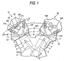
- Fig. 1 is a schematic view showing the construction of a V-engine having valve mechanisms to which the invention is applied.
- This V-engine has two cylinder banks 1F, 1R which are arranged so as to form the letter V, cylinder bores 3 which are formed in cylinder block portions 2 of the both cylinder banks 1F, 1R, pistons 4 which are arranged so as to slide fit in the bores 3, respectively, and a single crankshaft 6 which connects to the respective pistons 4 via connecting rods 5.
- Combustion chambers 8 inlet ports 10 of which the communication with the combustion chambers 8 is allowed and disallowed by inlet valves 9 and exhaust ports 12 of which the communication with the combustion chambers 8 is allowed and disallowed by exhaust valves 11 are provided in respective cylinder heads 7 of the two cylinder banks 1F, 1R.
- cams 14F, 14R which are arranged in a row, respectively, on camshafts 13F, 13R which are arranged so as to extend in a direction in which cylinders are arranged along an intermediate portion between the inlet valves 9 and the exhaust valves 10 on the respective cylinder banks 1F, 1R are transmitted to the inlet valves 9 and the exhaust valves 11, respectively, via inlet rocker-arms 15F, 15R and exhaust rocker-arms 16F, 16R, whereby the inlet and exhaust valves 9, 11 are driven to be opened and closed in synchronism with the rotation of the crankshaft 6 or, in other words, vertically reciprocating motions of the pistons 4.
- Valve operating conditions switching mechanisms 21e, 21s are incorporated in both the inlet and exhaust rocker-arms 15F, 16F of valve mechanisms on the cylinder bank 1F of the two cylinder banks 1F, 1R for stopping the operation of the inlet and exhaust valves 9, 11 so as to stop combustion cycles for a particular driving condition.
- the switching mechanisms 21e, 21s will briefly be described below by reference to Fig. 2.
- Fig. 2 illustrates valve mechanisms having the switching mechanisms 21e, 21s for a single cylinder. Note that this mechanism is provided for each of the cylinders on the cylinder bank 1F.
- an inlet rocker shaft which supports the inlet rocker-arms 15F for actuating the inlet valves 9 to open and close and an exhaust rocker shaft 23 which supports the exhaust rocker-arms 16F for actuating the exhaust valves 11 to open and close are arranged to extend in parallel in the direction in which the cylinders are arranged in a row in the cylinder banks in such a manner as to form an inverted triangle together with a single camshaft 13F which constitutes an apex of the triangle.
- two inlet valves 9 and two exhaust valves 11 are provided for eah cylinder.
- an inlet cam 14s for simultaneously actuating the two inlet valves 9 and two exhaust cams 14e for actuating the two exhaust valves 11 individually are formed adjacent to each other on the camshaft 13F for each cylinder in such a manner that the single inlet cam 14s is held between the two exhaust cams 14e.
- the inlet and exhaust rocker-arms 15F, 16F for transmitting the lifts of the inlet and exhaust cams 14s, 14e to the inlet and exhaust valves 9, 11, respectively, are divided into actuating rocker-arms 15d, 16d for bringing rollers 24 provided at one ends thereof into rolling contact with the corresponding cams 14s, 14e and follower rocker-arms 15i, 16i for bringing cam slippers 26 provided at one ends thereof into sliding contact with base circles 25 formed on the camshaft 13F and bringing tappet adjustment screws 27 provided at the other ends thereof into direct abutment with ends of valve stems, and on the inlet valves 9 side, three rocker-arms including a single actuating rocker-arm 15d corresponding to the single inlet cam 14s and two follower rocker-arms 15i corresponding individually to the two inlet valves 9 are pivotally supported on the inlet rocker shaft 22 in such a manner that the single actuating rocker-arm 15d is held between the two follower rocker-
- a first bottomed guide hole 31 which is made to open at an end thereof which faces towards the central actuating rocker-arm 15d is formed in one (an upper one in Fig. 2) of the follower rocker-arms 15i of the inlet valves 9 in parallel with an axis of the inlet rocker shaft 22, and a first connecting pin 32 is provided so as to slide fit in the guide hole so formed.
- This first connecting pin 32 is biased in a spring fashion towards the actuating rocker-arm 15d side at all times by means of a compression coil spring 33.
- a second guide hole 34 is formed to penetrate the actuating rocker-arm 15d in such a manner as to be concentric with the first guide hole 31 at a stationary position where the roller 24 abuts with a base circle portion B on the inlet cam 14s, and a second connecting pin 35 which is in abutment with the first connecting pin 32 at one end thereof is provided to slide fit in the second hole 34 so formed.
- a third guide hole 36 which is substantially bottomed as with the aforesaid follower rocker-arm 15i, is formed in the other follower rocker-arm 15i (a lower one in Fig. 2), and a stopper pin 37, which is made to abut with the other end of the second connecting pin 35 at one end thereof, is provided to slide fit in the third guide hole 36.
- Two oil supply passageways 41a, 41b are formed in the interior of the inlet rocker shaft 22 for sending under pressure lubricating oil pumped up from an oil pan. These two oil supply passageways 41a, 41b communicate with bottom portions of the first guide hole 31 and the third guide hole 36, respectively, via their corresponding communicating holes 42a, 42b formed in the pivotally supporting portions of the follower rocker-arms 15i and passageway holes 43a, 43b which are formed in the respective follower rocker-arms 15i.
- a first guide hole 51 and a second guide hole 52 which are both bottomed, are formed to extend in parallel with the axis of the exhaust rocker shaft 22 between the actuating rocker-arm 16d and the follower arm 16i which make a pair at positions which are aligned with each other at the stationary position where the roller 24 abuts with a base circle portion B of the exhaust cam 14e, and a connecting pin 53 and a stopper pin 54 are provided so as to slide fit in the holes so formed, respectively.
- the connecting pin 53 on the follower rocker-arm 16d side is biased in a spring fashion towards the actuating rocker-arm 16i side at all times by means of a compression coil spring 55.
- two oil supply passageways 44a, 44b are formed in the exhaust rocker shaft 23 for sending under pressure a lubricating oil pumped up from the oil pan , and the oil supply passageways 44a, 44b so formed communicate with bottom portions of the guide holes 51, 52 via communicating holes 45a, 45b formed in the respective pivotally supporting portions of both the follower and actuating rocker-arms 16d, 16i to which they correspond respectively and passageway holes 46a, 46b provided respectively in both the follower and actuating rocker-arms 16d, 16i.
- the switching mechanisms 21e, 21s are actuated by controlling electromagnetic valves (not shown) to open and close in accordance with the driving conditions of the engine so as to selectively switch oil pressures sent from the respective oil supply passageways 41a, 41b, 44a, 44b.
- valve lift amount (a solid line) of the front bank is caused to differ from the valve lift amount (dotted line) of the rear bank, in particular, in an overlap area of the inlet valve 9 and the exhaust valve 11, as shown in Fig. 4.
- This can be a cause for generating a change in revolution of the engine in a low-speed area.
- the profile of the cam lobe of the cam 14F formed on the camshaft 12F on the front bank 1F is made larger than the profile of the cam lobe of the cam 14R formed on the camshaft 14R on the rear bank 1R.
- a certain difference may be provided to cam profiles formed on the camshafts provided on the both banks so as to correct a difference in valve lift amount that is generated between the pluralities of cylinders due to the difference in rigidity of the valve mechanisms to thereby make the valve liftamountsofthepluralitiesofcylinderssubstantially uniform.
- the generation of a change in in-cylinder pressure between the front and rear banks 1F, 1R can be suppressed by making substantially uniform the actual valve lift amounts between the different banks.
- substantially uniform means a degree that can suppress a change in in-cylinder pressure between cylinders having valve mechanisms which are different in construction and rigidity, and the actual valve lift amount preferably becomes identical over all the cylinders.
- Fig. 7 shows another embodiment wherein a front side and a rear side are inverse to thereof of the embodiment shown in Fig. 1.
- Figs. 4 to 6 are also applied to the embodiment shown in Fig. 7.
- the cylinders having the valve trains fitted with the switching mechanisms are disposed on the front side of the engine, the increase in temperature of the valve trains on the front side of the engine can be suppressed by means of running air, and hence deformations can be prevented that would be caused by heat.
- the decrease in valve lift amount on the valve trains side of which the rigidity is lowered due to the provision of the switching mechanisms, and hence a difference in valve lift amount between the cylinders can be made as small as possible, whereby the cam profiles can be made smaller in size without being made larger than required.
- a difference in actual valve lift amount that occurs from cylinder to cylinder can be suppressed by setting cam profiles in consideration of the existence of a difference between the cylinders in the construction or rigidity of valve mechanisms or lift amount transmitting portions provided between cams and valves. Consequently, according to the invention, there can be provided a great advantage in further enhancement of the smoothness in engine revolutions, in particular, in a low-speed driving area.
- the increase in temperature of the valve trains on the front side of the engine can be suppressed by means of running air, and deformations can be prevented that would be caused by heat.
- the decrease in valve lift amount on the valve trains side of which the rigidity is lowered due to the provision of the switching mechanisms, and hence a difference in valve lift amount between the cylinders can be made as small as possible, whereby the cam profiles can be made smaller in size without being made larger than required.
- a valve operating conditions switching mechanism is provided on a front bank side, it is possible to perform a maintenance of a valve mechanism from a front side with a space.
- a valve operating conditions switching mechanism is provided on a rear bank side, since it is possible to stop a bank side nearer a drivers' seat, it is possible to reduce an effect of noise to the driver's seat.
- a constantly driven bank is located at a front side with respect to a traveling direction of a vehicle, it is possible to cool the bank which is more subject to a heat due to constant driving by running wind.
- a valve train for an internal combustion engine including a plurality of cylinders having different valve mechanism constructions, characterized in that the valve train has correcting member for correcting a difference in valve lift amount that is produced between the plurality of cylinders due to a difference in construction between valve mechanisms so as to make valve lift amounts of the plurality of cylinders substantially uniform.
Landscapes
- Engineering & Computer Science (AREA)
- Mechanical Engineering (AREA)
- General Engineering & Computer Science (AREA)
- Chemical & Material Sciences (AREA)
- Combustion & Propulsion (AREA)
- Valve Device For Special Equipments (AREA)
- Valve-Gear Or Valve Arrangements (AREA)
Applications Claiming Priority (2)
| Application Number | Priority Date | Filing Date | Title |
|---|---|---|---|
| JP2003172310 | 2003-06-17 | ||
| JP2003172310 | 2003-06-17 |
Publications (2)
| Publication Number | Publication Date |
|---|---|
| EP1489271A1 true EP1489271A1 (fr) | 2004-12-22 |
| EP1489271B1 EP1489271B1 (fr) | 2008-07-09 |
Family
ID=33410926
Family Applications (1)
| Application Number | Title | Priority Date | Filing Date |
|---|---|---|---|
| EP04014131A Expired - Fee Related EP1489271B1 (fr) | 2003-06-17 | 2004-06-16 | Système de commande de soupapes pour un moteur à combustion interne avec différents profiles de cames |
Country Status (4)
| Country | Link |
|---|---|
| US (1) | US7140334B2 (fr) |
| EP (1) | EP1489271B1 (fr) |
| CN (1) | CN100334332C (fr) |
| DE (1) | DE602004014852D1 (fr) |
Cited By (1)
| Publication number | Priority date | Publication date | Assignee | Title |
|---|---|---|---|---|
| US10465573B2 (en) | 2017-02-16 | 2019-11-05 | Toyota Jidosha Kabushiki Kaisha | Internal combustion engine system |
Families Citing this family (1)
| Publication number | Priority date | Publication date | Assignee | Title |
|---|---|---|---|---|
| DE102020113219A1 (de) | 2020-05-15 | 2021-11-18 | Schaeffler Technologies AG & Co. KG | Kipphebelanordnung für einen Ventiltrieb einer Brennkraftmaschine |
Citations (11)
| Publication number | Priority date | Publication date | Assignee | Title |
|---|---|---|---|---|
| GB166740A (en) * | 1920-04-28 | 1921-07-28 | Joseph Maina | Improvements in or relating to valve mechanism for internal combustion engines |
| GB191177A (en) * | 1921-10-11 | 1923-01-11 | Arthur John Amos | Improvements in valve adjustment devices |
| GB503105A (en) * | 1937-10-28 | 1939-03-31 | Robert Mcgregor | Improvements relating to valve-gear |
| GB734268A (en) * | 1951-06-27 | 1955-07-27 | Lanova Ag | Improved valve gear for internal combustion engines with valves arranged in the cylinder head |
| GB837665A (en) * | 1957-09-24 | 1960-06-15 | Ford Motor Co | Valve rocker gear for internal combustion engines |
| JPS5851204A (ja) * | 1981-09-21 | 1983-03-25 | Honda Motor Co Ltd | 多気筒内燃機関の動弁装置 |
| US4726331A (en) * | 1986-05-06 | 1988-02-23 | Yamaha Hatsudoki Kabushiki Kaisha | Means for variable valve timing for engine |
| EP0275714A1 (fr) * | 1986-12-27 | 1988-07-27 | Honda Giken Kogyo Kabushiki Kaisha | Mécanisme de commande de soupapes pour un moteur à combustion interne |
| EP0343627A1 (fr) * | 1988-05-26 | 1989-11-29 | Nissan Motor Co., Ltd. | Entraînement de soupapes pour moteur à combustion interne en V |
| DE4303789A1 (de) * | 1993-02-10 | 1994-08-18 | Iav Motor Gmbh | Schaltbare Mitnehmereinrichtung für gegeneinander schiebbare Hubübertragungselemente |
| EP0834647A1 (fr) * | 1996-10-07 | 1998-04-08 | Yamaha Hatsudoki Kabushiki Kaisha | Commande de soupape pour moteur |
Family Cites Families (4)
| Publication number | Priority date | Publication date | Assignee | Title |
|---|---|---|---|---|
| DE2753197A1 (de) * | 1976-12-15 | 1978-06-22 | Eaton Corp | Ventilsteuervorrichtung |
| EP0583583B1 (fr) * | 1992-07-16 | 1996-09-04 | Mitsubishi Jidosha Kogyo Kabushiki Kaisha | Moteur à combustion interne pour véhicule |
| JP3669688B2 (ja) | 2000-11-22 | 2005-07-13 | 本田技研工業株式会社 | 内燃機関 |
| JP3652598B2 (ja) * | 2000-11-22 | 2005-05-25 | 本田技研工業株式会社 | 内燃機関 |
-
2004
- 2004-06-16 EP EP04014131A patent/EP1489271B1/fr not_active Expired - Fee Related
- 2004-06-16 DE DE602004014852T patent/DE602004014852D1/de active Active
- 2004-06-16 CN CNB2004100481328A patent/CN100334332C/zh not_active Expired - Fee Related
- 2004-06-16 US US10/867,818 patent/US7140334B2/en not_active Expired - Fee Related
Patent Citations (11)
| Publication number | Priority date | Publication date | Assignee | Title |
|---|---|---|---|---|
| GB166740A (en) * | 1920-04-28 | 1921-07-28 | Joseph Maina | Improvements in or relating to valve mechanism for internal combustion engines |
| GB191177A (en) * | 1921-10-11 | 1923-01-11 | Arthur John Amos | Improvements in valve adjustment devices |
| GB503105A (en) * | 1937-10-28 | 1939-03-31 | Robert Mcgregor | Improvements relating to valve-gear |
| GB734268A (en) * | 1951-06-27 | 1955-07-27 | Lanova Ag | Improved valve gear for internal combustion engines with valves arranged in the cylinder head |
| GB837665A (en) * | 1957-09-24 | 1960-06-15 | Ford Motor Co | Valve rocker gear for internal combustion engines |
| JPS5851204A (ja) * | 1981-09-21 | 1983-03-25 | Honda Motor Co Ltd | 多気筒内燃機関の動弁装置 |
| US4726331A (en) * | 1986-05-06 | 1988-02-23 | Yamaha Hatsudoki Kabushiki Kaisha | Means for variable valve timing for engine |
| EP0275714A1 (fr) * | 1986-12-27 | 1988-07-27 | Honda Giken Kogyo Kabushiki Kaisha | Mécanisme de commande de soupapes pour un moteur à combustion interne |
| EP0343627A1 (fr) * | 1988-05-26 | 1989-11-29 | Nissan Motor Co., Ltd. | Entraînement de soupapes pour moteur à combustion interne en V |
| DE4303789A1 (de) * | 1993-02-10 | 1994-08-18 | Iav Motor Gmbh | Schaltbare Mitnehmereinrichtung für gegeneinander schiebbare Hubübertragungselemente |
| EP0834647A1 (fr) * | 1996-10-07 | 1998-04-08 | Yamaha Hatsudoki Kabushiki Kaisha | Commande de soupape pour moteur |
Non-Patent Citations (1)
| Title |
|---|
| PATENT ABSTRACTS OF JAPAN vol. 007, no. 137 (M - 222) 15 June 1983 (1983-06-15) * |
Cited By (1)
| Publication number | Priority date | Publication date | Assignee | Title |
|---|---|---|---|---|
| US10465573B2 (en) | 2017-02-16 | 2019-11-05 | Toyota Jidosha Kabushiki Kaisha | Internal combustion engine system |
Also Published As
| Publication number | Publication date |
|---|---|
| US20040255887A1 (en) | 2004-12-23 |
| CN1573033A (zh) | 2005-02-02 |
| DE602004014852D1 (de) | 2008-08-21 |
| US7140334B2 (en) | 2006-11-28 |
| EP1489271B1 (fr) | 2008-07-09 |
| CN100334332C (zh) | 2007-08-29 |
Similar Documents
| Publication | Publication Date | Title |
|---|---|---|
| US7503296B2 (en) | Cylinder deactivation apparatus | |
| US5359970A (en) | Valve drive for an internal combustion engine | |
| US7201125B2 (en) | Valve train for an internal combustion engine | |
| WO1991012413A1 (fr) | Moyen de commande de soupape | |
| US5370090A (en) | Multi-cylinder internal combustion engine | |
| WO2008100738A1 (fr) | Système d'actionnement de soupape à plusieurs étages | |
| US7849826B2 (en) | Valve system | |
| JPH05195736A (ja) | エンジンのバルブ駆動装置 | |
| US7156059B2 (en) | Variable valve train apparatus for an internal combustion engine | |
| JP2762213B2 (ja) | 内燃機関の動弁装置 | |
| EP1489271B1 (fr) | Système de commande de soupapes pour un moteur à combustion interne avec différents profiles de cames | |
| US6098581A (en) | Variable valve control for piston internal combustion engine | |
| EP2180152A1 (fr) | Dispositif de commande de soupape pour moteur à combustion interne | |
| JP3344236B2 (ja) | 内燃機関用バルブ駆動装置 | |
| US6615781B2 (en) | Overhead camshaft type valve train for internal combustion engine | |
| JP4423582B2 (ja) | エンジン | |
| JP2005030390A (ja) | 内燃機関の動弁装置 | |
| JP2001289019A (ja) | 内燃機関の動弁装置 | |
| JP3690130B2 (ja) | 3次元カム用揺動フォロワ機構 | |
| JP2005502808A (ja) | 内燃機関のための弁駆動装置 | |
| JP4539596B2 (ja) | 内燃機関の可変動弁装置 | |
| JP3274877B2 (ja) | エンジンの動弁装置 | |
| JP5586087B2 (ja) | 内燃機関の可変動弁機構 | |
| JP2783131B2 (ja) | 内燃機関用動弁装置 | |
| JP2002242625A (ja) | 内燃エンジンの可変動弁機構 |
Legal Events
| Date | Code | Title | Description |
|---|---|---|---|
| PUAI | Public reference made under article 153(3) epc to a published international application that has entered the european phase |
Free format text: ORIGINAL CODE: 0009012 |
|
| AK | Designated contracting states |
Kind code of ref document: A1 Designated state(s): AT BE BG CH CY CZ DE DK EE ES FI FR GB GR HU IE IT LI LU MC NL PL PT RO SE SI SK TR |
|
| AX | Request for extension of the european patent |
Extension state: AL HR LT LV MK |
|
| 17P | Request for examination filed |
Effective date: 20050124 |
|
| 17Q | First examination report despatched |
Effective date: 20050405 |
|
| AKX | Designation fees paid |
Designated state(s): DE GB |
|
| GRAP | Despatch of communication of intention to grant a patent |
Free format text: ORIGINAL CODE: EPIDOSNIGR1 |
|
| GRAS | Grant fee paid |
Free format text: ORIGINAL CODE: EPIDOSNIGR3 |
|
| GRAA | (expected) grant |
Free format text: ORIGINAL CODE: 0009210 |
|
| AK | Designated contracting states |
Kind code of ref document: B1 Designated state(s): DE GB |
|
| REG | Reference to a national code |
Ref country code: GB Ref legal event code: FG4D |
|
| REF | Corresponds to: |
Ref document number: 602004014852 Country of ref document: DE Date of ref document: 20080821 Kind code of ref document: P |
|
| PLBE | No opposition filed within time limit |
Free format text: ORIGINAL CODE: 0009261 |
|
| STAA | Information on the status of an ep patent application or granted ep patent |
Free format text: STATUS: NO OPPOSITION FILED WITHIN TIME LIMIT |
|
| 26N | No opposition filed |
Effective date: 20090414 |
|
| PGFP | Annual fee paid to national office [announced via postgrant information from national office to epo] |
Ref country code: GB Payment date: 20090610 Year of fee payment: 6 |
|
| GBPC | Gb: european patent ceased through non-payment of renewal fee |
Effective date: 20100616 |
|
| PG25 | Lapsed in a contracting state [announced via postgrant information from national office to epo] |
Ref country code: GB Free format text: LAPSE BECAUSE OF NON-PAYMENT OF DUE FEES Effective date: 20100616 |
|
| PGFP | Annual fee paid to national office [announced via postgrant information from national office to epo] |
Ref country code: DE Payment date: 20110608 Year of fee payment: 8 |
|
| REG | Reference to a national code |
Ref country code: DE Ref legal event code: R119 Ref document number: 602004014852 Country of ref document: DE Effective date: 20130101 |
|
| PG25 | Lapsed in a contracting state [announced via postgrant information from national office to epo] |
Ref country code: DE Free format text: LAPSE BECAUSE OF NON-PAYMENT OF DUE FEES Effective date: 20130101 |