EP1486758A2 - Bildmessverfahren und Bildmessvorrichtung - Google Patents
Bildmessverfahren und Bildmessvorrichtung Download PDFInfo
- Publication number
- EP1486758A2 EP1486758A2 EP04013672A EP04013672A EP1486758A2 EP 1486758 A2 EP1486758 A2 EP 1486758A2 EP 04013672 A EP04013672 A EP 04013672A EP 04013672 A EP04013672 A EP 04013672A EP 1486758 A2 EP1486758 A2 EP 1486758A2
- Authority
- EP
- European Patent Office
- Prior art keywords
- indicated value
- exposure time
- illuminance
- image
- unit
- Prior art date
- Legal status (The legal status is an assumption and is not a legal conclusion. Google has not performed a legal analysis and makes no representation as to the accuracy of the status listed.)
- Withdrawn
Links
Images



Classifications
-
- G—PHYSICS
- G01—MEASURING; TESTING
- G01B—MEASURING LENGTH, THICKNESS OR SIMILAR LINEAR DIMENSIONS; MEASURING ANGLES; MEASURING AREAS; MEASURING IRREGULARITIES OF SURFACES OR CONTOURS
- G01B11/00—Measuring arrangements characterised by the use of optical techniques
- G01B11/24—Measuring arrangements characterised by the use of optical techniques for measuring contours or curvatures
-
- G—PHYSICS
- G01—MEASURING; TESTING
- G01B—MEASURING LENGTH, THICKNESS OR SIMILAR LINEAR DIMENSIONS; MEASURING ANGLES; MEASURING AREAS; MEASURING IRREGULARITIES OF SURFACES OR CONTOURS
- G01B11/00—Measuring arrangements characterised by the use of optical techniques
- G01B11/02—Measuring arrangements characterised by the use of optical techniques for measuring length, width or thickness
Definitions
- the present invention relates to an image measuring method and an image measuring device. More specifically, this invention relates to an image measuring method of measuring a form or the like of a workpiece with an image measuring device comprising a luminance-variable illumination unit and an image pick-up unit by irradiating illumination light from the illumination unit to the workpiece and picking-up the reflected light from the workpiece, and measuring a form or other parameters of the workpiece from the picked-up image, and also relates to the image measuring device.
- an image measuring device comprising an illumination unit for irradiating illumination light to a workpiece and an image pick-up unit for picking-up reflected light from the workpiece and capable of measuring a form, dimensions, and colors of the workpiece by subjecting the image picked-up by the image pick-up unit to image processing according to the necessity (Refer to, for instance, Japanese Patent Laid-Open Publication No. 2000-9459).
- This image measuring device comprises a CCD camera for picking-up an image of a workpiece and outputting image data thereof, and a ring illumination unit for irradiating illumination light to the workpiece.
- This illumination unit is connected via an optical fiber cable to a light-emitting source such as a halogen lamp provided in a power supply unit.
- the image measuring device further comprises an illumination control device for controlling luminance of the light-emitting source by controlling a current applied to the light-emitting source and an input section provided operable from the outside.
- the illumination control device when a user instructs luminance of the illumination light with the input section, applies a specified current to the light-emitting source so that the illumination light is irradiated with the specified luminance.
- the illumination light is irradiated to the workpiece with the illuminance instructed by applying a current.
- the reflected light from the workpiece is received by the CCD camera, and a form, dimensions, colors and other parameter of the workpiece can be measured by detecting edges or other parameters from the picked-up image.
- illumination light irradiated to a workpiece namely illuminance of the workpiece irradiated by the illumination light is very important.
- illuminance of actual illumination is lower than a specified illuminance
- the light volume is insufficient and an image can not be obtained, or edge detection can not be carried out.
- the illuminance of actual illumination is higher than the specified illuminance, the light is saturated, so that the image is fogged and edge detection can not be carried out also in this case.
- a response speed in control is high and an obliquity of the illumination light can be controlled.
- a response speed in luminance control is low.
- a halogen lamp has other disadvantages, for instance, that the power consumption is large and the service life is short.
- the use of many halogen lamps in combination with the optical fiber cable is not preferable and hence it is difficult to control obliquity of illumination light by providing ON/OFF control over illumination light irradiated from each fiber cable.
- an image measuring device using, as a light-emitting source, a semiconductor light-emitting element (LED: Light Emitting Diode) having such advantages as a high response speed, low power consumption, and long service life and adapted to being ON/OFF controlled discretely (such as an image probe described in Japanese Patent Laid-Open Publication No. 2001-154098).
- LED Light Emitting Diode
- This image measuring device comprises a CCD camera, an image pick-up optical system for picking-up an image of the workpiece with the CCD camera, a reflected illumination unit for illuminating the workpiece with reflected light, and a ring illumination unit for illuminating the workpiece in the diagonal direction from a position around the image pick-up optical system.
- Each of the illumination units as described above has a light source comprising a plurality of light-emitting diodes, and further comprises an illumination optical system for guiding illumination light from the light source.
- illumination units are also based on the configuration as described above in which illuminance can be controlled by an illumination control device. Further the plurality of light-emitting diodes can be turned ON or OFF discretely or block by block for light adjustment, so that the illumination light can be irradiated to the workpiece in any direction. Therefore, by using light-emitting diodes as a light source, size reduction as well as weight reduction of the illumination unit can be realized, and there are provided the advantages that the control speed is higher, power consumption is smaller, and the service life is longer as compared to those in a halogen lamp.
- brightness of a picked-up image is decided by luminance of a light-emitting source put under control, namely by illuminance of a workpiece, so that the brightness of obtained image can be limited within a controllable illuminance range, so that there occur the problems as described below.
- a light-emitting diode when used as a light-emitting source, the luminance of a light-emitting diode is lower as compared to that of a halogen lamp, and sometimes brightness of the image may be insufficient.
- Further light-emitting diodes have the individual difference specified to each product, and the luminance varies from product to product, so that luminance control is carried out according to a product having low luminance, and therefore luminance of the entire illumination unit is suppressed to a low level. It is conceivable that products each having low luminance are screened off and only light-emitting diodes each having high luminance are used, but selection of the products as described above will result in cost increase.
- the following countermeasures as using a light-emitting source having higher luminance, increasing a number of installed light-emitting sources, and raising a gain (amplification factor) of a CCD camera can be considered to raise brightness of a picked-up image, but when the countermeasures as described above are taken, the problems as described below occur.
- the heat release is high, which may sometimes give negative effects over the precision in measurement. Also when a larger number of light-emitting sources are installed, the heat release becomes higher, and such problems as increase of power consumption or increase in size of the illumination unit occur. When a gain of the CCD camera is raised, noises mixed in a picked-up image increase, which will result in the lower precision in measurement.
- the present invention provides an image measuring method, with use of a luminance-variable illumination unit and an image pick-up unit with variable exposure time, in which an illumination light is irradiated from the illumination unit to a workpiece, and a reflected light from and/or transmitted light through the workpiece is picked up by the image pick-up unit, so that the workpiece is measured based on a picked-up image
- the method including: an illuminance computing step of obtaining illuminance of the workpiece based on luminance of the illumination unit according to an indicated value set and inputted from the outside; and an exposure time computing step of computing an exposure time for the image pick-up unit, in which, in the illuminance computing step, the illuminance is computed so that the illuminance increases up to a preset illuminance in association with increase of the indicated value when the indicated value is not higher than a prespecified indicated value, and the illuminance is kept at the preset illuminance when the indicated value is higher than the prespecified indicated value,
- Brightness of a picked-up image is obtained by multiplying illuminance of a workpiece based on luminance of an illumination unit by an exposure time of the image pick-up unit, and even when illuminance of the workpiece is constant, brightness of the image becomes brighter by prolonging the exposure time of the image pick-up unit in proportion to the prolonged exposure time.
- the prespecified indicated value can be set to any value within a range in which the prespecified indicated value is not larger than an indicated value (100% indicated value) corresponding to the maximum luminance (the maximum illuminance of the workpiece) in the range where the illumination is generally used.
- illuminance of a workpiece based on the luminance of an illumination unit and an exposure time of an image pick-up unit are computed based on an indicated value set and inputted from the outside in the illuminance computing step and the exposure time computing step respectively, and the illumination unit and the image pick-up unit are controlled according to the illuminance and the exposure time computed as described above, so that it is possible to pick-up an image of the brightness obtained by simultaneously satisfying illuminance of a workpiece and an exposure time of an image pick-up unit.
- an indicated value when an indicated value is not higher than a prespecified indicated value, by controlling luminance on an illumination unit to raise or lower illuminance of a workpiece and also by keeping an exposure time of an image pick-up unit at a constant value, measurement can be carried out by the method of controlling an illumination unit and the method of controlling an exposure time of an image pick-up unit like those in the conventional technology.
- the indicated value is larger than the prespecified indicated value, by keeping luminance of the illumination unit at a constant value and also prolonging or shortening an exposure time of the image pick-up unit, brightness of an image can continuously be controlled.
- the illumination unit and the image pick-up unit are automatically controlled according to an indicated value, and also brightness of a picked-up image changes, so that the operator is not required to control the illumination unit or the image pick-up unit, and can carry out an image measurement of a workpiece only by inputting an indicated value.
- the illuminance computing step when the indicated value is not higher than the prespecified indicated value, the illuminance is computed so that the illuminance increases with a constant increment according to the indicated value
- the exposure time computing step when the indicated value is higher than the prespecified indicated value, the exposure time is computed so that the exposure time increases with a constant increment according to the indicated value and also so that brightness of the image obtained by the combination of the computed illuminance and the computed exposure time continuously increases with a constant increment according to the indicated value.
- the illuminance computing step when the indicated value is not higher than the prespecified indicated value, the illuminance is computed so that the illuminance increases with an increment along a curve defined by a prespecified function according to an increment of the indicated value, and in the exposure time computing step, when the indicated value is higher than the prespecified indicated value, the exposure time is computed so that the exposure time increases with an increment along a curve defined by a prespecified function according to an increment of the indicated value and also so that brightness of the image obtained by the combination of the computed illuminance and the computed exposure time continuously increases with an increment along a curve defined by a prespecified function according to the indicated value.
- illuminance and an exposure time are controlled so that the parameters will increase with an increment along a curve defined with a prespecified function according to an indicated value, and brightness of an image continuously increases with an increment along a curve defined with a prespecified function according to an indicated value, and therefore an increment for brightness of an image can freely be set in response to a region of an indicated value, thus precision in measurement being improved.
- an indicated value and brightness of an image is defined with a function for reducing an increment in a region where an indicated value is small (a dark region)
- brightness of an image in a dark region can be controlled finely, so that precision in measurement can be improved.
- the prespecified indicated value corresponds to a maximum luminance in a range in which the illumination unit is generally used.
- an indicated value (100% indicated value) corresponding to the maximum luminance in a range in which the illumination unit is generally used as a prespecified indicated value by setting an indicated value (100% indicated value) corresponding to the maximum luminance in a range in which the illumination unit is generally used as a prespecified indicated value, and therefore luminance of an illumination unit can be controlled according to an indicated value not higher than the 100% indicated value within the range up to the maximum luminance, and when the indicated value surpassed the 100% indicated value, luminance of the illumination unit is kept constant at the maximum luminance. Therefore, the illumination capability of an illumination unit can effectively be utilized to its limit, so that illumination can be carried out efficiently.
- the prespecified indicated value corresponds to a luminance lower by a prespecified percentage against the maximum luminance in the range where the illumination unit is generally used.
- luminance of an illumination unit is controlled in a range up to the value lower than the maximum luminance when an indicated value is not larger than the prespecified value, and the luminance of the illumination unit is kept constant at the luminance lower than the maximum luminance when the indicated value surpasses the prespecified indicated value.
- the present invention provides an image measuring device comprising a luminance-variable illumination unit and an image pick-up unit with variable exposure time, in which an illumination light is irradiated from the illumination unit to a workpiece, and a reflected light from and/or transmitted light through the workpiece is picked up by the image pick-up unit, so that the workpiece is measured based on a picked-up image
- the image measuring device further including: an illuminance controller for controlling illuminance of the workpiece based on luminance of the illumination unit according to an indicated value set and inputted from the outside; and an exposure time controller for controlling an exposure time for the image pick-up unit, in which the illuminance controller controls the illumination unit so that the illuminance increases up to a preset illuminance in association with increase of the indicated value when the indicated value is not higher than a prespecified indicated value, and also so that the illumination is kept at the preset illuminance when the indicated value is higher than the prespecified indicated value, and the exposure time controller controls the image pick-
- the illumination unit and the image pick-up unit are automatically controlled according to an indicated value, so that a measuring person is not required to control the illumination unit or the image pick-up unit discretely, and a measurement workpiece can easily be carried out only by inputting an indicated value.
- the illuminance controller controls the illumination unit so that the illuminance increases with a constant increment according to the indicated value
- the exposure time controller controls the image pick-up unit so that the exposure time increases with a constant increment according to the indicated value and also so that brightness of the image obtained by the combination of the computed illuminance and the computed exposure time continuously increases with a constant increment according to the indicated value.
- the illuminance controller controls the illumination unit so that the illuminance increases with an increment along a curve defined by a prespecified function according to the indicated value
- the exposure time controller controls the image pick-up unit so that the exposure time increases with an increment along a curve defined by a prespecified function according to an increment of the indicated value and also so that brightness of the image obtained by the combination of the computed illuminance and the computed exposure time continuously increased along a curve defined by a prespecified function according to the indicated value.
- an increment of brightness of an image can freely be set with a prespecified function in correspondence to a region of an indicated value, so that precision in measurement can be improved.
- the illumination unit preferably includes a plurality of semiconductor light-emitting elements.
- the image measuring device includes a plurality of semiconductor elements as a light-emitting source, so that reduction in both the size and weight of an illumination unit can be realized, and a higher control speed, smaller power consumption, and longer service life can be realized as compared to those provided when a halogen lamp is used.
- the image pick-up unit preferably includes a camera having a solid state image pick-up element.
- CMOS device Complementary Metal-Oxide Semiconductor device
- an image of a workpiece picked-up with a CCD camera or the like can quickly be transferred as image data for subjecting the image data to image processing or the like, so that the efficiency in a measurement workpiece can be improved.
- a CCD camera or the like it is easy to control the exposure time with an electric control signal, and therefore control over an exposure time can be carried out more accurately as compared to an ordinary camera having a shutter device or the like based on a mechanical system.
- images can be picked up successively at a prespecified frame rate, so that the operations from a step of inputting an indicated value up to a step of checking brightness of an image can be carried out successively, and therefore the efficiency in a measurement workpiece can further be improved.
- the image measuring device preferably has a computer comprising an input unit for inputting the indicated value; a storage unit for storing therein a relation among the indicated value, the illuminance, and the exposure time when the illumination unit and the image pick-up unit are controlled; a computing unit for computing illuminance and exposure time based on an indicated value inputted with the input unit as well as on the relation among the indicated value, the illuminance, and the exposure time stored in the storage unit; an image processor for processing the picked-up image; and a display unit for displaying thereon the image processed by the image processor, and in this image measuring device, the illuminance controller is integrated with the computer or is separately provided and controls the illumination unit according to the illuminance computed by the computing unit; and the exposure time controller is integrated with the computer or is separately provided and controls the image pick-up unit according to the exposure time computed by the computing unit.
- a relation among an indicated value, illuminance, and an exposure time stored in the storage unit may be a relational expression for computing illuminance and an exposure time according to an indicated value as a parameter, or may be a table showing combinations of illuminance and an exposure time for various indicated values.
- illuminance and an exposure time with a computing unit (such as a CPU) based on the relation among an indicated value, illuminance, and an exposure time stored in a storage unit (such as a memory or a hard disk) provided in a computer, illuminance and an exposure time can quickly be computed from an indicated value inputted with an input section (such as a keyboard, buttons, or a lever), so that time required for measurement can be shortened with the efficiency in a measurement workpiece improved.
- a computing unit such as a CPU
- a storage unit such as a memory or a hard disk
- Fig. 1 to Fig. 4 show an image measuring device 1 according to a first embodiment of the present invention
- Fig. 5A to Fig. 6C show image measuring methods according to second and third embodiments of the present invention respectively.
- Fig. 1 is a view showing general configuration of the image measuring device 1 according to this embodiment.
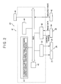
- Fig. 2 is a block diagram showing configuration of the image measuring device 1.
- Fig. 3A to Fig. 3C are views each showing a relation among an indicated value, illuminance, an exposure time, and brightness of an image in the image measuring device 1.
- Fig. 4 is a flow chart showing an image measuring method in the image measuring device 1.
- the image measuring device 1 comprises a device body 10 for irradiating illumination light to a workpiece W as a workpiece and picking up reflected light from the workpiece W, and a device controller 40 for processing an image of the workpiece W picked-up by this device body 10 and also controlling operations of the device body 10.
- the device body 10 and the device controller 40 are connected to each other via a cable 2.
- the device body 10 comprises a housing 11 having a form like a hollow box, a stage 12 for placing the workpiece W thereon, an illumination unit 20 for irradiating illumination light to the workpiece W placed on the housing 11, and an image pick-up unit 30 provided inside the housing 11 for picking up an image of the workpiece W by receiving reflected light therefrom.
- a housing 11 having a form like a hollow box, a stage 12 for placing the workpiece W thereon, an illumination unit 20 for irradiating illumination light to the workpiece W placed on the housing 11, and an image pick-up unit 30 provided inside the housing 11 for picking up an image of the workpiece W by receiving reflected light therefrom.
- an opening around an optical axis A perpendicular to an upper surface of the stage 12 and extending in the vertical direction and the reflected light from the workpiece W reaches the image pick-up unit 30 through this opening.
- housing 11 and the stage 12 can manually or automatically be moved in two directions on a plane crossing the optical axis A (directions X and Y), and in the direction along the optical axis A (direction Z), so that adjustment for a portion of the workpiece W to be measured or focus adjustment of the image pick-up unit 30 can be carried out.
- the illumination unit 20 comprises a reflected illuminator 21 provided inside the housing 11 for irradiating illumination light from above the workpiece W along the optical axis A, and a diagonal illuminator 25 provided on a bottom surface of the housing 11 and around the optical axis A for irradiating a ring-formed beam of illumination light from the direction diagonal to the optical axis A to the workpiece W.
- the reflected illuminator 21 comprises a halogen lamp 22 as a light-emitting source for irradiating illumination light in the direction perpendicular to the optical axis A, a lens 23 for focusing illumination light diffusing from the halogen lamp 22, and a half-mirror 24 provided on the optical axis A for reflecting the illumination light from the halogen lamp 22 toward the workpiece W.
- the diagonal illuminator 25 comprises a hollow and ring-formed housing 26 around the optical axis A as a center, and a white light-emitting diode (LED) 27 provided inside the housing 26 as a light-emitting source.
- LED white light-emitting diode
- a plurality of LEDs 27 are provided in a ring from around the optical axis A.
- the diagonal illuminator 25 is divided in four directions when viewed from the top, namely to a front section, a back section, a left section, and a right section. Amplitudes of illumination lights on the front section, back section, left section, and right section are controlled independently respectively.
- the image pick-up unit 30 comprises condenser lenses 31, 32 provided along the optical axis A each for condensing reflected light from the workpiece W, and a CCD camera 34 having charge-coupled devices 33 for receiving light from the condenser lenses 31, 32.
- the CCD camera 34 receives reflected light from the workpiece W with the charge-coupled device 33 to pick-up an image of the workpiece W.
- the picked-up image is image data consisting of a finite number of pixels, and the image size is, for instance, 512 x 512 pixels.
- Each pixel is, for instance, 8-bit data, and the 8-bit data indicates an amplitude of received light with one of gradation level (received light amplitude values) classified to 256 grades from 0 to 255.
- the image data from the CCD camera 34 is outputted via the cable 2 to the device controller 40.
- the CCD camera 34 can fetch several dozens of frames, for instance, 30 frames of images successively within one second. Further in the CCD camera 34, the shutter speed can be changed and adjusted by specifying an exposure time by inputting a necessary parameter.
- the range of exposure time adjustment is, for instance, from 1/10000 second to 2 seconds.
- the device controller 40 comprises a computer 41 for receiving image data from the CCD camera 34, subjecting the image data to image processing, and outputting the processed image data for display; an illumination controller 50 provided as a single body and separated from the computer 41 for adjusting luminance of the illumination unit 20 to control illumination of the workpiece W, and a frame grabber 60 as an exposure time controller integrated as the computer 41 for controlling an exposure time of the image pick-up unit 30.
- the illumination controller 50 controls illuminance of the workpiece W by receiving an indicated value from the computer 41 and adjusting a current applied to the illumination unit 20 to adjust luminance of the illumination unit 20.
- the frame grabber 60 receives an indicated value from the computer 41 and transmits an exposure time control signal to the image pick-up unit 30 to control an exposure time of the CCD camera 34.
- the illumination controller may be integrated with the computer 41, and the exposure time controller may be provided as a signal body separated from the computer 41.
- the computer 41 comprises an input section 42 for setting and inputting an indicated value instructing illuminance of the workpiece W an exposure time of the CCD camera 34 based on luminance of the illumination unit 20, and a memory 43 as a storage section for storing therein a relation among the indicated value, illuminance, and an exposure time.
- the computer 41 comprises an image processor 44 as an image processing unit for processing image data from the CCD camera 34, and a display unit (CRT) 45 as a display section for outputting and displaying a result of processing in the image processor 44.
- the computer 41 comprises a CPU (Central Processing Unit) 46 as a computing unit for controlling the entire device controller 40, and the CPU 46 is connected to the input section 42, memory 43, image processor 44, and CRT 45 via a bus.
- CPU Central Processing Unit
- the illumination unit 50 and the frame grabber 60 can be incorporated as a portion of functions installed in the computer 41 as the illumination controller (illumination control unit) 50 and the camera controller (frame grabber) 60. Further the configuration is allowable in which the illumination controller or the exposure time controller is stored as programmed software in the memory 43, and controls for illuminance and an exposure time are executed by computing the image data with the CPU 46 to transmit a control signal to the illumination unit 20 or the image pick-up unit 30.
- the input section 42 comprises a lever, a button or the like exposed to the outside and manually operable.
- the input section 42 is used to input illuminance of the workpiece W and an exposure time of the image pick-up unit 30, for instance, in a range from 0% to 200%.
- the indicated value set and inputted in the input section 42 is transmitted via a bus to the CPU 46.
- the CPU 46 reads out an illumination control conditional expression and an camera control conditional expression stored in the memory 43 and has the program for computing the expressions executed to compute illuminance of the workpiece W and an exposure time of the image pick-up unit 30 adapted to an indicated value sent from the input section 42. Then the CPU 46 instructs the computed illuminance to the illumination controller (illumination control unit) 50, and also instructs the computed exposure time to the camera controller (frame grabber) 60.
- the illumination controller (illumination control unit) 50 receives an indicated value from the CPU 46, and makes each of the illuminators 21, 25 irradiate illumination light by applying a current corresponding to the indicated value to each of the light-emitting sources 22, 27 of the controllers 21, 25.
- the camera controller (frame grabber) 60 receives the indicated value from the CPU 46, and transmits a pulse with the pulse width corresponding to the instructed exposure time as a control signal (external trigger signal) to the CCD camera 34 to set a shutter speed of the CCD camera 34.
- the method of controlling an exposure time of the CCD camera 34 is not limited that in which an external trigger signal is transmitted to the CCD camera 34 via the frame grabber 60, and the configuration is allowable in which, with a camera having an exposure time control mechanism, information for an exposure time is transmitted from the computer 41 to the camera through an RS 232C cable or the like.
- the image processor 44 processes the image data picked up by the CCD camera 34 to detect edges or the like, and computes a form, dimensions, and colors of the workpiece W by computing the image data.
- the CRT 45 displays a result of image measurement computed by the image processor 44.
- the illumination control conditional expression and the camera control conditional expression stored in the memory 43 are defined in this embodiment as described below.
- a prespecified indicated value is an indicated value (an indicated value for 100 %) corresponding to the maximum luminance in a range in which the light-emitting sources 22, 27 in the illumination unit 20 are generally used.
- "1" indicates the reference illuminance [1x], which is equal to 1/100 of the maximum illuminance corresponding to the maximum luminance in each of the light-emitting sources 22, 27.
- illuminance is computed so that the illuminance increases with a constant increment up to prespecified illuminance (maximum illuminance) in proportion to an indicated value when the indicated value is not larger than the 100% indicated value, and also so that the illuminance is preserved at the maximum illuminance (100 ⁇ 1) previously set when the indicated value is larger than the 100% indicated value.
- x indicates an indicated value
- "e" indicates the reference exposure time [sec], which is set to 1/30 sec corresponding to the general frame rate of 30 fps in the CCD camera 34.
- the exposure time is computed so that the exposure time is preserved at a prespecified exposure time (1/30 sec) when the indicated value is not larger than the 100% indicated value, and also so that the exposure time increases with a constant increment in proportion to the indicated value when the indicated value is larger than the 100% indicated value.
- the exposure time is set to 1/15 sec in response to the indicated value of 200% which is two times longer than the constant exposure time (1/30 sec) described above.
- Brightness of an image picked up by the CCD camera 34 is decided from the illuminance L and the exposure time E computed through the illumination control conditional expression and the camera control conditional expression as described above.
- the brightness G of the image is in proportion to a product of the illuminance L and the exposure time E as well as to g which is a constant decided by a gain in the CCD camera 34 and the number of apertures (NA) of the condenser lenses 31, 32, and is computed through the following expression (1)
- G g ⁇ L ⁇ E
- the CPU 46 When an indicated value is inputted, the CPU 46 reads out the illumination control conditional expression from the memory 43, and computes the illuminance L of the workpiece W (luminance of the illumination unit 20) based on the indicated value x (ST2), and then the CPU 46 reads out the camera control conditional expression from the memory 43, and computes the exposure time E of the image pick-up unit 30 based on the indicated value x (ST3).
- the illumination computing step comprises the step ST2
- the exposure time computing step comprises the step ST3.
- luminance of the illumination unit 20 and the CCD camera 34 are controlled according to the computed illuminance L and exposure time E, and illumination light is irradiated to the workpiece W, an image of the workpiece W is picked up by the CCD camera 34, and the picked-up image data is inputted into the image processor 44 (ST4). Then the image processor 44 executes image processing (ST5) with a result of image measurement displayed on the CRT 45 (ST6).
- step ST7 a measuring person visually checks brightness of an image which is the displayed result of image measurement, and determines whether the image brightness is acceptable or not.
- image brightness namely that image information for the workpiece W (the form, dimensions, colors and the like) is displayed with the sufficiently recognizable brightness
- measurement is finished.
- image brightness namely that the displayed image is dark and detection of edges or the like can not be executed sufficiently, or when the displayed image is too bright and the image can not visually be identified sufficiently, an indicated value is inputted again (ST1'), and the measurement is continued.
- the operation for inputting again an indicated value (ST1') according to a result of determination as to acceptability of the image brightness (ST7) can be executed successively.
- the CCD camera 34 can fetch several dozens of image frames successively, and also can successively process images of the workpiece W fetched as described above with the image processor 44 and successively displayed the processes images on the CRT 45.
- the measuring person can successively input and update indicated values by monitoring the images as results of measurement successively displayed on the CRT 45 and operating the input section 42. Because of the feature, the operations from step ST1' to ST7 can successively be carried out in repetition until brightness of an image picked up based on the illuminance and an exposure time based on the indicated value inputted again becomes acceptable.
- Any frame rate of images successively displayed on the CRT45 is allowable on the condition that the frame rate is around 7.5 fps or more, and therefore the exposure time can be prolonged up to about four times of 1/30 sec (up to 1/7.5 sec).
- Fig. 5A to Fig. 5C show a relation among an indicated value, illuminance, an exposure time, and brightness of an image in this embodiment.
- Configuration of the image measuring device 1 and the image measuring method in this embodiment are substantially the same as those described in the first embodiment above, and is different from the first embodiment only in the expression for setting a relation among the indicated value x, illuminance L, and exposure time E. The difference is described in detail below.
- the illumination control conditional expression for computing the illuminance L of the workpiece W and the camera control conditional expression for computing the exposure time E of the image pick-up unit 30 are defined in this embodiment as described below.
- the prespecified indicated value is that (indicated by the sign A in Fig. 5A) corresponding to luminance lower by a prespecified percentage as compared to the maximum luminance in a range in which the light-emitting sources 22, 27 in the illumination unit are generally used.
- the luminance lower by a prespecified percentage is, for instance, that lower by A% as compared to the maximum luminance (A% illuminance), and an indicated value corresponding to the A% illuminance is an A% indicated value.
- the illuminance L is computed as described below respectively.
- the illuminance L is computed so that the illuminance increases with a constant increment up to the preset illuminance (A% illuminance) in proportion to an indicated value when an indicated value is not larger than the A% indicated value, and also so that the illuminance is preserved at the preset illuminance (A% illuminance) when the indicated value is larger than the A% indicated value.
- the exposure time E is computed as described below respectively.
- the exposure time E is computed so that the exposure time is preserved at the preset exposure time e (for instance, 1/30 sec) when the indicated value is not larger than the A% indicated value, and also so that the exposure time will increase with a constant increment in proportion to an indicated value when the indicated value is larger than the A% indicated value.
- the exposure time of the image pick-up unit 30 is set to 1/30 sec when the indicated value is not larger than the 80% indicated value, the exposure time is about 1/24 sec which is longer by about 20% than that for the 100% indicated value. Therefore, the frame rate lowers by about 24 fps (corresponding to that at the exposure time of 1/24 sec) for the 100% indicated value, but any problem occurs in the practical use, and operations for image measurement can smoothly be carried out.
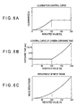
- Fig. 6A to Fig. 6C are views each showing a relation among an indicated value, illuminance, an exposure time, and brightness of an image.
- Configuration of the image measuring device 1 and the image measuring method in this embodiment are the substantially same as those in the first embodiment described above, but are different from the first embodiment only in the expression for computing a relation among an indicated value x, illuminance L, an exposure time, and brightness of an image. The difference is described in detail below.
- the illumination control conditional expression for computing illuminance L of a workpiece W and the camera control conditional expression for computing an exposure time E of the image pick-up unit 30 are defined in this embodiment as described below.
- the prespecified indicated value is that corresponding to the maximum luminance in a range where the light-emitting sources 22, 27 in the illumination unit 20 are generally used (100% indicated value).
- the illuminance L is computed as described below respectively.
- the relation between an indicated value and illuminance is indicated by the illumination control curve shown in Fig. 6A.
- the illuminance L is computed so that the illuminance increases with a increment along the curve defined by the function 1 (x) according to an indicated value up to the maximum illuminance when the indicated value is not larger than the 100% indicated value, and also so that the illuminance is preserved at the present illuminance (maximum illuminance) when the indicated value is larger than the 100% indicated value.
- the exposure time E is computed as described below respectively.
- the exposure time E is computed so that the exposure time is preserved at a preset exposure time e (for instance, 1/30 sec) when the indicated value is not larger than the 100% indicated value, and also so that the exposure time will increase with an increments along a curve defined by the function 1 (x) according to an indicated value when the indicated value is larger than the 100% indicated value.
- the brightness G of an image is computed by substituting the illuminance L and exposure time E computed through the illumination control conditional expression and through the camera control conditional expression respectively into the expression (1) above as described below.
- the function 1 (x) draws a curve having a downward convex form, and the increment becomes smaller in a region when the indicated value is small (dark). Namely, brightness of an image can be controlled finely even in a dark region.
- the function 1 (x) is not limited to that giving a downward convex form, and may be that giving an upward convex form, and also the curvature may be inverted according to an indicated value.
- the image measuring method and image measuring device according to the present invention are not limited to those described in the embodiments described above, and various changes and modification can be made within departing from the gist of the present invention.
- the image measuring device 1 comprises the device body 10 and the device controller 40 which are discrete bodies respectively in each of the embodiments described above, but the present invention is not limited to this configuration, and the configuration is allowable in which the device body and the device controller are integrated with each other.
- the illumination unit 20 and the image pick-up unit 30 are integrated with the device body 10 in each of the embodiments described above, but the configuration is allowable in which the illumination unit or the image pick-up unit is provided as a single body.
- illuminance of a workpiece W is adjusted by the illumination controller 50 controlling a current applied to the halogen lamp 22 or the light-emitting diode 27 which is a light-emitting source for the illumination unit 20 to adjust luminance of the illumination unit 20, but the present invention is not limited to the configuration, and the configuration is allowable in which luminance of the illumination unit is adjusted by increasing or reducing a number of the light-emitting sources.
- the device controller 40 has the computer 41 comprising the memory 43, the image processor 44, or the CPU 46, but the present invention is not limited to this configuration, and a storage device or a computing device may be provided as a single body respectively.
- the device controller 40 is not limited to that connected via a cable to the device body 10, and the device controller 40 may have the configuration in which transactions of control signals and image data are carried out with a radio communication device or the like.
- the illumination unit 20 comprises the reflected illuminator 21 and the diagonal illuminator 25, but the present invention is not limited to this configuration, and only either one of the components may be provided, and further a device for transmitted illumination for irradiating illumination light from the lower side of the stage 12 toward an image pick-up unit through the workpiece W may be employed.
- a device for transmitted illumination for irradiating illumination light from the lower side of the stage 12 toward an image pick-up unit through the workpiece W may be employed.
Landscapes
- Physics & Mathematics (AREA)
- General Physics & Mathematics (AREA)
- Length Measuring Devices By Optical Means (AREA)
- Spectrometry And Color Measurement (AREA)
- Investigating Materials By The Use Of Optical Means Adapted For Particular Applications (AREA)
- Investigating Or Analysing Materials By Optical Means (AREA)
- Photometry And Measurement Of Optical Pulse Characteristics (AREA)
Applications Claiming Priority (2)
| Application Number | Priority Date | Filing Date | Title |
|---|---|---|---|
| JP2003163976A JP2005003385A (ja) | 2003-06-09 | 2003-06-09 | 画像測定方法、および画像測定装置 |
| JP2003163976 | 2003-06-09 |
Publications (2)
| Publication Number | Publication Date |
|---|---|
| EP1486758A2 true EP1486758A2 (de) | 2004-12-15 |
| EP1486758A3 EP1486758A3 (de) | 2006-10-18 |
Family
ID=33296792
Family Applications (1)
| Application Number | Title | Priority Date | Filing Date |
|---|---|---|---|
| EP04013672A Withdrawn EP1486758A3 (de) | 2003-06-09 | 2004-06-09 | Bildmessverfahren und Bildmessvorrichtung |
Country Status (4)
| Country | Link |
|---|---|
| US (1) | US20040246367A1 (de) |
| EP (1) | EP1486758A3 (de) |
| JP (1) | JP2005003385A (de) |
| CN (1) | CN1573283A (de) |
Cited By (2)
| Publication number | Priority date | Publication date | Assignee | Title |
|---|---|---|---|---|
| CN102377947A (zh) * | 2011-09-02 | 2012-03-14 | 深圳市先河系统技术有限公司 | 曝光控制装置及方法 |
| EP2479536A3 (de) * | 2011-01-20 | 2012-09-12 | Mitutoyo Corporation | Optische Messvorrichtung mit Autofokus |
Families Citing this family (28)
| Publication number | Priority date | Publication date | Assignee | Title |
|---|---|---|---|---|
| JP2008249418A (ja) * | 2007-03-29 | 2008-10-16 | Dkk Toa Corp | 測定装置用光源モジュール及び測定装置 |
| JP2008249411A (ja) * | 2007-03-29 | 2008-10-16 | Dkk Toa Corp | 測定装置用光源モジュール及び測定装置 |
| JP2010096564A (ja) * | 2008-10-15 | 2010-04-30 | Mitsutoyo Corp | 画像処理装置、及び画像測定機 |
| JP5556346B2 (ja) * | 2010-05-11 | 2014-07-23 | 株式会社Sumco | ウェーハ欠陥検査装置及びウェーハ欠陥検査方法 |
| US8573497B2 (en) | 2010-06-30 | 2013-11-05 | Datalogic ADC, Inc. | Adaptive data reader and method of operating |
| US9122939B2 (en) | 2010-09-16 | 2015-09-01 | Datalogic ADC, Inc. | System and method for reading optical codes on reflective surfaces while minimizing flicker perception of pulsed illumination |
| JP5668227B2 (ja) * | 2011-02-17 | 2015-02-12 | 株式会社ミツトヨ | 画像測定装置 |
| US8646692B2 (en) * | 2011-09-30 | 2014-02-11 | Hand Held Products, Inc. | Devices and methods employing dual target auto exposure |
| JP6053790B2 (ja) * | 2012-07-25 | 2016-12-27 | 富士機械製造株式会社 | 撮像装置および電子部品実装機 |
| CN103488026A (zh) * | 2013-09-05 | 2014-01-01 | 广东欧珀移动通信有限公司 | 调节摄像头补光灯亮度的方法和系统 |
| CN105849746A (zh) * | 2013-12-27 | 2016-08-10 | 三菱电机株式会社 | 二维码读取装置 |
| JP6278741B2 (ja) * | 2014-02-27 | 2018-02-14 | 株式会社キーエンス | 画像測定器 |
| JP6290651B2 (ja) * | 2014-02-27 | 2018-03-07 | 株式会社キーエンス | 画像測定器 |
| US9386222B2 (en) * | 2014-06-20 | 2016-07-05 | Qualcomm Incorporated | Multi-camera system using folded optics free from parallax artifacts |
| CN104865188A (zh) * | 2015-05-28 | 2015-08-26 | 歌尔声学股份有限公司 | 一种视觉检测控制方法及系统 |
| JP2017003469A (ja) * | 2015-06-11 | 2017-01-05 | キヤノン株式会社 | 三次元計測装置、三次元計測装置の制御方法及びプログラム |
| US9594936B1 (en) | 2015-11-04 | 2017-03-14 | Datalogic Usa, Inc. | System and method for improved reading of data from reflective surfaces of electronic devices |
| US10467457B2 (en) * | 2015-12-03 | 2019-11-05 | Nec Corporation Of America | System and method for capturing images used in facial recognition through effective use of exposure management |
| CN105868766A (zh) * | 2016-03-28 | 2016-08-17 | 浙江工业大学 | 喷涂流水线工件自动检测与识别方法 |
| EP3505910B1 (de) | 2016-11-30 | 2022-01-12 | JFE Steel Corporation | Vorrichtung zur messung des pulververhältnisses und system zur messung des pulververhältnisses |
| JP7026115B2 (ja) * | 2017-07-18 | 2022-02-25 | 株式会社Fuji | 部品実装機 |
| JP7178541B2 (ja) * | 2018-02-07 | 2022-11-28 | パナソニックIpマネジメント株式会社 | 発光部品実装装置および発光部品実装方法 |
| CN108419345B (zh) * | 2018-03-19 | 2019-08-16 | 深圳前海华夏智信数据科技有限公司 | 基于图像分析的控灯方法及装置 |
| CN108668127B (zh) * | 2018-08-01 | 2019-09-27 | 昆山丘钛微电子科技有限公司 | 成像设备曝光时间测试装置 |
| CN111343389B (zh) * | 2019-05-16 | 2021-09-10 | 杭州海康慧影科技有限公司 | 一种自动曝光控制方法及装置 |
| CN111367138A (zh) * | 2020-04-14 | 2020-07-03 | 长春理工大学 | 一种新型激光扫描投影装置 |
| JP7602195B2 (ja) | 2021-01-27 | 2024-12-18 | オムロン株式会社 | 撮影条件設定システム、撮影条件設定方法及びプログラム |
| CN113281341A (zh) * | 2021-04-19 | 2021-08-20 | 唐山学院 | 热镀锌带钢的双传感器表面质量检测系统的检测优化方法 |
Family Cites Families (7)
| Publication number | Priority date | Publication date | Assignee | Title |
|---|---|---|---|---|
| US4560267A (en) * | 1982-03-26 | 1985-12-24 | Minolta Camera Kabushiki Kaisha | Camera system operable by carrying data from a camera accessory to a camera body |
| ATE237793T1 (de) * | 1996-07-29 | 2003-05-15 | Elpatronic Ag | Verfahren und vorrichtung zur kantenverfolgung und kantenprüfung |
| US6303916B1 (en) * | 1998-12-24 | 2001-10-16 | Mitutoyo Corporation | Systems and methods for generating reproducible illumination |
| WO2001035049A1 (en) * | 1999-11-08 | 2001-05-17 | Matsushita Electric Industrial Co., Ltd. | Method and apparatus for component recognition |
| WO2001073375A1 (en) * | 2000-03-31 | 2001-10-04 | Omron Corporation | Displacement sensor |
| JP2002014057A (ja) * | 2000-06-30 | 2002-01-18 | Nidek Co Ltd | 欠陥検査装置 |
| JP2003269919A (ja) * | 2002-03-11 | 2003-09-25 | Mitsutoyo Corp | 画像処理型測定機の照明装置 |
-
2003
- 2003-06-09 JP JP2003163976A patent/JP2005003385A/ja not_active Withdrawn
-
2004
- 2004-06-04 US US10/860,070 patent/US20040246367A1/en not_active Abandoned
- 2004-06-09 CN CN200410047962.9A patent/CN1573283A/zh active Pending
- 2004-06-09 EP EP04013672A patent/EP1486758A3/de not_active Withdrawn
Cited By (5)
| Publication number | Priority date | Publication date | Assignee | Title |
|---|---|---|---|---|
| EP2479536A3 (de) * | 2011-01-20 | 2012-09-12 | Mitutoyo Corporation | Optische Messvorrichtung mit Autofokus |
| EP2607840A1 (de) * | 2011-01-20 | 2013-06-26 | Mitutoyo Corporation | Optische Messvorrichtung mit Autofokus |
| US8866114B2 (en) | 2011-01-20 | 2014-10-21 | Mitutoyo Corporation | Vision measuring device |
| CN102377947A (zh) * | 2011-09-02 | 2012-03-14 | 深圳市先河系统技术有限公司 | 曝光控制装置及方法 |
| CN102377947B (zh) * | 2011-09-02 | 2013-11-20 | 深圳市先河系统技术有限公司 | 曝光控制装置及方法 |
Also Published As
| Publication number | Publication date |
|---|---|
| US20040246367A1 (en) | 2004-12-09 |
| EP1486758A3 (de) | 2006-10-18 |
| JP2005003385A (ja) | 2005-01-06 |
| CN1573283A (zh) | 2005-02-02 |
Similar Documents
| Publication | Publication Date | Title |
|---|---|---|
| EP1486758A2 (de) | Bildmessverfahren und Bildmessvorrichtung | |
| JP6208901B2 (ja) | 目追跡装置動作方法及び能動的電力管理を行う目追跡装置 | |
| US6545703B1 (en) | Electronic endoscope | |
| US6980227B2 (en) | Electronic endoscope with light-amount adjustment apparatus | |
| US5142359A (en) | Electronic endoscope | |
| US8295559B2 (en) | Face image pickup device and method | |
| US7695138B2 (en) | Safe eye detection | |
| US6654062B1 (en) | Electronic camera | |
| JP5743392B2 (ja) | 手術用照明、カメラおよびモニタを備えた装置 | |
| US8496330B2 (en) | Ophthalmologic imaging apparatus and method for controlling the same | |
| JP7578177B2 (ja) | 情報処理装置、情報処理方法及びプログラム | |
| JP4223778B2 (ja) | 内視鏡用自動調光装置および電子内視鏡装置 | |
| US8436320B2 (en) | Fluorescence detecting apparatus, and fluorescence detecting method | |
| CN110381806B (zh) | 电子内窥镜系统 | |
| US6641529B2 (en) | Endoscope apparatus and method of controlling same | |
| JP2024507108A (ja) | 内視鏡カメラ関心領域の自動露出 | |
| US9386917B2 (en) | Light intensity control apparatus, light intensity control method, program, and ophthalmologic apparatus | |
| CN109414120B (zh) | 用于提供语义信息的装置以及操作其的方法 | |
| JP2002238846A (ja) | 内視鏡用光源装置 | |
| JP2020168174A (ja) | 電子内視鏡システム | |
| EP4364637A1 (de) | Prozessor für endoskop und endoskopsystem | |
| JP2002023062A (ja) | レーザ顕微鏡の照明光学系の調整方法 | |
| JP2006019901A (ja) | 視覚センサ | |
| JPH07241270A (ja) | 光源電圧可変式電子内視鏡装置 | |
| JPH07178046A (ja) | 内視鏡装置 |
Legal Events
| Date | Code | Title | Description |
|---|---|---|---|
| PUAI | Public reference made under article 153(3) epc to a published international application that has entered the european phase |
Free format text: ORIGINAL CODE: 0009012 |
|
| AK | Designated contracting states |
Kind code of ref document: A2 Designated state(s): AT BE BG CH CY CZ DE DK EE ES FI FR GB GR HU IE IT LI LU MC NL PL PT RO SE SI SK TR |
|
| AX | Request for extension of the european patent |
Extension state: AL HR LT LV MK |
|
| PUAL | Search report despatched |
Free format text: ORIGINAL CODE: 0009013 |
|
| AK | Designated contracting states |
Kind code of ref document: A3 Designated state(s): AT BE BG CH CY CZ DE DK EE ES FI FR GB GR HU IE IT LI LU MC NL PL PT RO SE SI SK TR |
|
| AX | Request for extension of the european patent |
Extension state: AL HR LT LV MK |
|
| AKX | Designation fees paid | ||
| STAA | Information on the status of an ep patent application or granted ep patent |
Free format text: STATUS: THE APPLICATION IS DEEMED TO BE WITHDRAWN |
|
| 18D | Application deemed to be withdrawn |
Effective date: 20070419 |
|
| REG | Reference to a national code |
Ref country code: DE Ref legal event code: 8566 |