EP1486631A2 - Griffbeschlag für Türen oder Klappen von Fahrzeugen - Google Patents
Griffbeschlag für Türen oder Klappen von Fahrzeugen Download PDFInfo
- Publication number
- EP1486631A2 EP1486631A2 EP04013705A EP04013705A EP1486631A2 EP 1486631 A2 EP1486631 A2 EP 1486631A2 EP 04013705 A EP04013705 A EP 04013705A EP 04013705 A EP04013705 A EP 04013705A EP 1486631 A2 EP1486631 A2 EP 1486631A2
- Authority
- EP
- European Patent Office
- Prior art keywords
- bolt
- tower
- carrier
- door
- handle
- Prior art date
- Legal status (The legal status is an assumption and is not a legal conclusion. Google has not performed a legal analysis and makes no representation as to the accuracy of the status listed.)
- Granted
Links
- 238000006073 displacement reaction Methods 0.000 description 3
- 238000009434 installation Methods 0.000 description 3
- 230000000452 restraining effect Effects 0.000 description 3
- 230000006835 compression Effects 0.000 description 2
- 238000007906 compression Methods 0.000 description 2
- 239000000969 carrier Substances 0.000 description 1
- 238000003780 insertion Methods 0.000 description 1
- 230000037431 insertion Effects 0.000 description 1
- 238000009413 insulation Methods 0.000 description 1
- 238000004519 manufacturing process Methods 0.000 description 1
- 230000007704 transition Effects 0.000 description 1
Images


Classifications
-
- E—FIXED CONSTRUCTIONS
- E05—LOCKS; KEYS; WINDOW OR DOOR FITTINGS; SAFES
- E05B—LOCKS; ACCESSORIES THEREFOR; HANDCUFFS
- E05B79/00—Mounting or connecting vehicle locks or parts thereof
- E05B79/02—Mounting of vehicle locks or parts thereof
- E05B79/06—Mounting of handles, e.g. to the wing or to the lock
-
- E—FIXED CONSTRUCTIONS
- E05—LOCKS; KEYS; WINDOW OR DOOR FITTINGS; SAFES
- E05B—LOCKS; ACCESSORIES THEREFOR; HANDCUFFS
- E05B77/00—Vehicle locks characterised by special functions or purposes
- E05B77/44—Burglar prevention, e.g. protecting against opening by unauthorised tools
-
- E—FIXED CONSTRUCTIONS
- E05—LOCKS; KEYS; WINDOW OR DOOR FITTINGS; SAFES
- E05B—LOCKS; ACCESSORIES THEREFOR; HANDCUFFS
- E05B9/00—Lock casings or latch-mechanism casings ; Fastening locks or fasteners or parts thereof to the wing
- E05B9/08—Fastening locks or fasteners or parts thereof, e.g. the casings of latch-bolt locks or cylinder locks to the wing
- E05B9/084—Fastening of lock cylinders, plugs or cores
Definitions
- the invention relates to a handle fitting in the preamble of Claim 1 specified type.
- this restricting movement essentially comprises one Inserting the tower perpendicular to the beam through an opening in the Carrier, which is then a shift phase in the direction of the carrier followed. Shoulders on the tower drive behind counter shoulders on the carrier. to Securing the mounting position of the tower serves as a holding means across the tower running screw which can be screwed into a thread holder of the carrier. The screw is accessible from the side through an opening in the rebate area of the door runs with its thread axis in the direction of the displacement phase of the tower assembly.
- the tower also positively mounted in the carrier by a restraining movement. Even there serves as a holding device to secure the mounting position of the tower a screw.
- This screw is accessible from the inside of the door. The screw penetrates a fastening point in the carrier and is in a thread in the screwable area of the tower, which, as described above, comes after the assembly on the outside of the door next to the handle.
- the Screw has the double function here, on the one hand, the form-fitting Secure assembly of the tower and on the other hand to secure the External paneling of the door to serve on the carrier.
- the screw runs in the direction of the Rails in the carrier and is accessible through a side opening in the door rebate.
- the form fit between the tower and the beam only comes through the Slider.
- a manually operated holding device to secure the Form-locking of the tower on the beam is not provided.
- the strength of the tower's mounting position depends on handle fittings with slider on the strength of the slide in the carrier. This handle fitting is space and costly because a slide, a slide guide on the carrier, a screw for actuating the slide and a storage of the screw in the Carriers are required.
- the invention has for its object an inexpensive handle fitting in The preamble of claim 1 to develop the type The risk of theft of vehicles equipped with this fitting has been improved. According to the invention, this is achieved by the measures specified in claim 1 achieved, which have the following special meaning.
- a one-piece latch arranged on the carrier, which has a locking end and an actuating end.
- the bolt end is moved and adjusted in conformity between a locking position and an unlocking position.
- the tower has a receptacle for the bolt end, in which the bolt end in the locking position retracts.
- the bolt is at least in the direction the locking position of its bolt end is spring-loaded.
- the actuation end of the Riegel is at least in the unlocked position from the inside of the door accessible. This means that the bolt provided on the carrier is from the outside for unauthorized persons cannot be manipulated in the area of its bolt end or its actuating end.
- the toggle spring engages the beam on one end and the bolt on the other and determines two stable end positions of the on both sides of a central dead center position Bar. In one end position, the locking end is in the Locking position and in the other end position is the unlocking position of the bolt end.
- the locking end is in the Locking position and in the other end position is the unlocking position of the bolt end.
- This point must be in be accessible from the inside of the door. All other areas of the Beam and the door can easily be occupied by other components. This allows a particularly intensive use of the inside of the door.
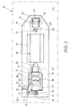
- the handle fitting shown in FIGS. 1 and 2 comprises a carrier 10, which on the in 1 visible inside of a door or flap at two points 13, 14th can be attached.
- a carrier 10 which on the in 1 visible inside of a door or flap at two points 13, 14th can be attached.
- dash-dot lines in Fig. 1 only a portion 12 of the External paneling of the door indicated.
- openings 15, 16 and 17 of the carrier 10 further components of the handle fitting are visible.
- the handle 20 which has two angled ends 21, 22.
- the handle 20 is of the type shown in FIG. 1 not visible outside of the door 12 through two openings in the Door outer panel mounted manually, at least in some areas with the Breakthroughs 15 and 17 of the carrier 10 are aligned.
- One end of the handle 21 is in Bearing points 18 of the carrier 10 hooked in, which is caused by a steering movement happens. This results in a swivel axis 23 which is illustrated in dash-dot lines for the handle 20.
- the other end of the handle 22 also takes part in this steering movement part, which has a hook head 24 at its inner end, which in Use case on the back of the carrier with a in the door interlocking linkage not shown, e.g. a lock lever. This end of the handle 22 with the hook head 24 passes through the third mentioned Breakthrough 17 in the carrier 10 a.
- the opening 17 is in the present case with a narrow and wide range Mistake.
- the tower 30 already mentioned is mounted. That can also done by a manual steering movement.
- the tower also has it 30 two shoulders 31, 32, which behind the wall areas of the Carrier 10 drive that in the transition between the narrow and wide range of third opening 17 are arranged.
- the tower has 30 another tab 35, which is part of the aforementioned second Attachment point 14 is.
- the attachment point 14 includes, in addition to the actual screw with its screw head 34, too another thread in the tower 30.
- the screw at the attachment point 14 is used finally also for fastening the outer paneling of the door 12 to the carrier 10.
- the carrier 10 has a latch 25, which in the present case is designed as a one-piece rotary bolt.
- the Carrier 10 has an axis of rotation 19, which in the present case essentially runs perpendicular to the door plane and on which the bolt 25 is rotatably mounted.
- the Bolt 25 has an active actuating end 27 and a passive, the bolt end 26 following the actuation.
- the bolt 25 is by a spring 28 force-loaded, the spring load indicated by the arrow 29 strives for Bolt 25 in its illustrated by the auxiliary line 25.1 in Fig. 1 Transfer locking position.
- This locking position 25.1 results because the bolt end 26 moves into a receptacle 36 of the tower 30.
- the recording 36 can include the bolt end 26 on all sides, such as a pocket, which is why not only the expansion of the tower, but also its further impression inside the door be prevented.
- the spring 28 is of course more tensioned than in the locking position 25.1 and generates a greater restoring force 29. This does not interfere, however, because screwing and unscrewing the screw head 34 itself a turning tool is located here anyway, which is the latch actuating end 27 can hold back.
- the actuating end 27 of the bolt 25 itself the same place where the one attachment point 14 of the carrier 10th is present.
- the screw at the attachment point 14 is otherwise as described was, at the same time, the holding means for securing the tower 30 to the carrier 10.
- This Position 27 is therefore for a tool from the inside of the door in any case accessible, while all other areas on the inside of the door from others Components of the door, such as insulation, can be covered.
- the Lock cylinder 37 has a cylinder outlet 38, which on the security and Unlocking means acts in the lock when the lock cylinder 37 by a Key is turned.
- 3 and 4 is another embodiment of an inventive Handle fitting shown. The same will be used to name analog components Reference numerals as used in the previous embodiment, why insofar as the previous description applies. It is only enough for the differences enter into.
- FIG. 3 illustrates torque on the bolt 25. This will its bolt end 26 moves clockwise according to the arrow 45.1 of FIG. 3. There is then, as the auxiliary line 25.1 in FIG. 3 illustrates Locking position of the rotary latch 25 before. Then, like in the first one Embodiment, the second attachment point 14 free to the screw 34 to be able to tighten or loosen. In this case too, the screw 34 serves as Holding means for securing the tower 30 to the carrier and not in detail in FIG. 3 exterior door trim shown.
- the second connection point 42.2 is then below the also shown in FIG. 4 by dash-dotted lines, already mentioned dead center line 43 this second end position 42.2, the rocker spring 40 exerts a torque in Counterclockwise on the actuating end 27, which in Fig. 4 with 44.2 is illustrated. Then the bolt end 26 is counterclockwise Direction of the arrow 45.2 out of the pocket of the tower 30. It is the Unlocking position 25.2 of the already described in the first embodiment Twist lock 25 before. Now the tower can be moved backwards 30 disassembled from the carrier.
- the area of the carrier 10 that receives the tower 30 is also serves to pivot the bolt 25, an insert 39 made for itself, which is firmly connected to the carrier before use.
- The has the advantage of a uniform carrier base, in which then if necessary different inserts 39 can be inserted to support for to produce different types of buildings or towers 30.
Landscapes
- Lock And Its Accessories (AREA)
Abstract
Description
- Fig. 1
- schematisch, von der Türinnenseite aus, die Draufsicht auf ein erstes Ausführungsbeispiel des erfindungsgemäßen Griffbeschlags mit einem in der Tür befestigten Träger, und zwar im Gebrauchsfall,
- Fig. 2
- in einer der Fig. 1 entsprechenden Darstellung den Montagefall, wo ein Turm im Träger montiert bzw. demontiert werden soll,
- Fig. 3
- ein zweites Ausführungsbeispiel des erfindungsgemäßen Griffbeschlags, wo zur Federbelastung eines Riegels eine sogenannte "Kippfeder" dient, und zwar in der Verriegelungsposition des Riegels, und
- Fig. 4
- den Griffbeschlag von Fig. 3, wenn die Entriegelungsposition des Riegels vorliegt.
- 10
- Träger
- 11
- Türinnenseite
- 12
- Tür
- 13
- erste Befestigungsstelle von 10 an 12
- 14
- zweite Befestigungsstelle von 10 an 12
- 15
- erster Durchbruch in 10
- 16
- zweiter Durchbruch in 10
- 17
- dritter Durchbruch in 10
- 18
- Lagerstellen in 10 für 21
- 19
- Drehachse für 25 an 10
- 20
- Griff
- 21
- erstes Griffende von 20
- 22
- zweites Griffende von 20
- 23
- Schwenkachse von 20 an 10
- 24
- Hakenkopf an 22
- 25
- Riegel, Drehriegel
- 25.1
- Verriegelungsposition von 25 (Fig. 1)
- 25.2
- Entriegelungsposition von 25 (Fig. 2)
- 26
- Riegelende von 25
- 27
- Betätigungsende von 25
- 28
- Feder für 25
- 29
- Pfeil der Federbelastung von 25
- 30
- Turm
- 31
- erste Schulter an 30
- 32
- zweite Schulter an 30
- 33
- Schraubenkopf von 13
- 34
- Schraubenkopf von 14
- 35
- Lappen an 30
- 36
- Aufnahme in 30 für 26 (Fig. 1)
- 37
- Schließzylinder in 30
- 38
- Zylinderausgang von 37
- 39
- Einsatz in 10 (Fig. 3, 4)
- 40
- Kippfeder (Fig. 3, 4)
- 41
- erste ortsfeste Anschlussstelle von 40
- 42.1
- erste Endlage der zweiten beweglichen Anschlussstelle von 40 (Fig. 3)
- 42.2
- zweite Endlage, zweite bewegliche Anschlussstelle von 40 (Fig. 4)
- 43
- Totpunktlinie für 40 durch 19,41
- 44.1
- Drehmoment an 27 bei 42.1 (Fig. 3)
- 44.2
- Drehmoment an 27 bei 42.2 (Fig. 3)
- 45.1
- Drehpfeil an 26 bei 42.1
- 45.2
- Drehpfeil an 26 bei 42.2
- 46
- Handhabe, Rippe an 27
Claims (9)
- Griffbeschlag für Türen (12) oder Klappen von Fahrzeugen,
mit einem an der Türinnenseite (11) zu befestigenden Träger (10) mit mindestens einer Befestigungsstelle (14)
mit einem von der Türaußenseite aus manuell im Träger (10) montierbaren, schwenkbaren oder drehbaren Griff (20)
und mit einem ebenfalls von der Türaußenseite aus neben dem Griff (20) montierbaren Schließzylinderturm oder einer Turmattrappe (Turm 30),
wobei der Turm (30) seinerseits manuell unmittelbar im Träger (10) formschlüssig (31, 32) montierbar ist
und der Formschluss des Turms (30) am Träger (10) mittels eines am Träger (10) angreifenden, manuell betätigbaren Haltemittels (14, 34) sicherbar ist,
dadurch gekennzeichnet , dass außer dem Haltemittel (14) auch noch ein einstückig ausgebildeter Riegel am Träger angeordnet ist, der ein Riegelende und ein Betätigungsende aufweist,
dass bei Betätigung das Riegelende sich konform mit dem Betätigungsende bewegt und zwischen einer Verriegelungsposition (25.1) und einer Entriegelungsposition (25.2) verstellt wird,
dass der Turm (30) eine Aufnahme (36) für das Riegelende (26) aufweist, in welche das Riegelende (26) in der Verriegelungsposition (25.1) einfährt und
dass der Riegel (25) mindestens in Richtung der Verriegelungsposition (25.1) seines Riegelendes (26) federbelastet ist. - Griffbeschlag nach Anspruch 1, dadurch gekennzeichnet, dass eine Kippfeder (40) einerends (41) am Träger und anderends am Riegel (25) angreift und beidseits einer mittigen Totpunktlage (43) zwei stabile Endlagen ihrer am Riegel (25) angreifenden Angriffsstelle (42.1, 42.2) bestimmt,
nämlich die Verriegelungsposition seines Riegelendes (26) einerseits und die Entriegelungsposition (25.2) des Riegelendes (26) andererseits. - Griffbeschlag nach Anspruch 1 oder 2, dadurch gekennzeichnet, dass das Haltemittel für den Turm (30) am Träger (10) zugleich die Befestigungsstelle (14) des Trägers (10) an der Tür (12) ist.
- Griffbeschlag nach Anspruch 1 bis 3, dadurch gekennzeichnet, dass die von der Türinnenseite (11) aus bequem zugängliche Stelle für das Betätigungsende (27) des Riegels (25) in jenem Türbereich angeordnet ist, wo sich auch die Handhabe (34) zur Befestigung (14) des Trägers (10) an der Tür (12) befindet.
- Griffbeschlag nach einem oder mehreren der Ansprüche 1 bis 4, dadurch gekennzeichnet, dass der Riegel (25) ein Drehriegel ist, dessen Drehachse (19) am Träger (10) sitzt.
- Griffbeschlag nach Anspruch 5, dadurch gekennzeichnet, dass die Drehachse (19) des Drehriegels (25) im wesentlichen senkrecht zur Türebene angeordnet. ist.
- Griffbeschlag nach Anspruch 5, dadurch gekennzeichnet, dass die Drehachse des Drehriegels im wesentlichen parallel zur Türebene verläuft.
- Griffbeschlag nach einem der Ansprüche 1 bis 7, dadurch gekennzeichnet, dass der Riegel (25) in Richtung seiner Entriegelungsposition (25.2) federbelastet (40) ist.
- Griffbeschlag nach einem oder mehreren der Ansprüche 1 bis 8, dadurch gekennzeichnet, dass der Träger (10) mit einem Einsatz (39) versehen ist, der den Turm (30) aufnimmt und/oder der den Riegel (25) lagert und/oder an dem das Haltemittel (14) für den Turm und Träger angreift.
Applications Claiming Priority (2)
| Application Number | Priority Date | Filing Date | Title |
|---|---|---|---|
| DE10327081A DE10327081A1 (de) | 2003-06-13 | 2003-06-13 | Griffbeschlag für Türen oder Klappen von Fahrzeugen |
| DE10327081 | 2003-06-13 |
Publications (3)
| Publication Number | Publication Date |
|---|---|
| EP1486631A2 true EP1486631A2 (de) | 2004-12-15 |
| EP1486631A3 EP1486631A3 (de) | 2006-01-04 |
| EP1486631B1 EP1486631B1 (de) | 2009-02-25 |
Family
ID=33185804
Family Applications (1)
| Application Number | Title | Priority Date | Filing Date |
|---|---|---|---|
| EP04013705A Expired - Lifetime EP1486631B1 (de) | 2003-06-13 | 2004-06-11 | Griffbeschlag für Türen oder Klappen von Fahrzeugen |
Country Status (3)
| Country | Link |
|---|---|
| EP (1) | EP1486631B1 (de) |
| AT (1) | ATE423881T1 (de) |
| DE (2) | DE10327081A1 (de) |
Cited By (1)
| Publication number | Priority date | Publication date | Assignee | Title |
|---|---|---|---|---|
| US20250075536A1 (en) * | 2023-08-28 | 2025-03-06 | Hushan Autoparts Inc. | Car tailgate handle base reinforcement repair method and structure |
Citations (4)
| Publication number | Priority date | Publication date | Assignee | Title |
|---|---|---|---|---|
| DE3030519C2 (de) | 1980-08-13 | 1983-01-27 | Daimler-Benz Ag, 7000 Stuttgart | Außenliegender Ziehgriff, insbesondere für Kraftfahrzeugtüren |
| DE19633894A1 (de) | 1996-08-22 | 1998-02-26 | Huf Huelsbeck & Fuerst Gmbh | Vorrichtung zur Betätigung eines in einer Tür, einer Klappe o. dgl. eingebauten Schlosses, insbesondere bei einem Fahrzeug |
| DE19950172A1 (de) | 1999-10-19 | 2001-04-26 | Huf Huelsbeck & Fuerst Gmbh | Griffbeschlag, insbesondere für eine Kraftfahrzeugtür |
| DE10146026C1 (de) | 2001-09-18 | 2002-10-31 | Huf Huelsbeck & Fuerst Gmbh | Griffbeschlag |
Family Cites Families (3)
| Publication number | Priority date | Publication date | Assignee | Title |
|---|---|---|---|---|
| US5706554A (en) * | 1994-12-02 | 1998-01-13 | Ewald Witte Gmbh & Co. Kg | Handle fitting, which can be inserted into an opening in a door, particularly a motor-vehicle door |
| JP3216994B2 (ja) * | 1996-06-26 | 2001-10-09 | 三井金属鉱業株式会社 | 車両用ドアキーシリンダ取付装置 |
| IT1311353B1 (it) * | 1999-11-12 | 2002-03-12 | Valeo Sicurezza Abitacolo Spa | Maniglia di una porta di un veicolo. |
-
2003
- 2003-06-13 DE DE10327081A patent/DE10327081A1/de not_active Withdrawn
-
2004
- 2004-06-11 AT AT04013705T patent/ATE423881T1/de not_active IP Right Cessation
- 2004-06-11 DE DE502004009035T patent/DE502004009035D1/de not_active Expired - Lifetime
- 2004-06-11 EP EP04013705A patent/EP1486631B1/de not_active Expired - Lifetime
Patent Citations (4)
| Publication number | Priority date | Publication date | Assignee | Title |
|---|---|---|---|---|
| DE3030519C2 (de) | 1980-08-13 | 1983-01-27 | Daimler-Benz Ag, 7000 Stuttgart | Außenliegender Ziehgriff, insbesondere für Kraftfahrzeugtüren |
| DE19633894A1 (de) | 1996-08-22 | 1998-02-26 | Huf Huelsbeck & Fuerst Gmbh | Vorrichtung zur Betätigung eines in einer Tür, einer Klappe o. dgl. eingebauten Schlosses, insbesondere bei einem Fahrzeug |
| DE19950172A1 (de) | 1999-10-19 | 2001-04-26 | Huf Huelsbeck & Fuerst Gmbh | Griffbeschlag, insbesondere für eine Kraftfahrzeugtür |
| DE10146026C1 (de) | 2001-09-18 | 2002-10-31 | Huf Huelsbeck & Fuerst Gmbh | Griffbeschlag |
Cited By (1)
| Publication number | Priority date | Publication date | Assignee | Title |
|---|---|---|---|---|
| US20250075536A1 (en) * | 2023-08-28 | 2025-03-06 | Hushan Autoparts Inc. | Car tailgate handle base reinforcement repair method and structure |
Also Published As
| Publication number | Publication date |
|---|---|
| DE502004009035D1 (de) | 2009-04-09 |
| EP1486631B1 (de) | 2009-02-25 |
| DE10327081A1 (de) | 2005-01-13 |
| ATE423881T1 (de) | 2009-03-15 |
| EP1486631A3 (de) | 2006-01-04 |
Similar Documents
| Publication | Publication Date | Title |
|---|---|---|
| DE69532799T2 (de) | Verriegelung für einen behälter | |
| DE112007000324T5 (de) | Türeingangsschloss | |
| DE60219774T2 (de) | Ventilsperrvorrichtung | |
| DE10146026C1 (de) | Griffbeschlag | |
| EP2267256A2 (de) | Bügelschloss | |
| EP1555363A1 (de) | Betätigungsvorrichtung für Türen oder Klappen an Fahrzeugen | |
| DE2522301A1 (de) | Tuerverriegelung fuer kraftfahrzeuge | |
| DE4244414C2 (de) | Verschluß für Fenster, Türen u. dgl. | |
| EP3887621B1 (de) | Modulares verschlusssystem | |
| EP3222801A1 (de) | Schloss für wertbehältnisse | |
| DE29509503U1 (de) | Mehrfachverriegelungsanlage | |
| EP1486631B1 (de) | Griffbeschlag für Türen oder Klappen von Fahrzeugen | |
| EP0239855B1 (de) | Schloss für eine Tür, ein Fenster oder dergleichen | |
| AT398108B (de) | Schlossplatte | |
| DE10309946A1 (de) | Schloß | |
| EP1505227A2 (de) | Vorrichtung zur Betätigung eines Schlosses an einer Tür oder Klappe eines Fahrzeugs | |
| DE4013439A1 (de) | Mit schlosseinrichtung versehener versenkbarer schwenkhebelverschluss | |
| DE29803239U1 (de) | Türschließvorrichtung | |
| DE69113565T2 (de) | Zylinderschloss. | |
| DE102025110908B3 (de) | Rahmenschloss für ein Fahrrad | |
| DE9104766U1 (de) | Antipaniktürschloß | |
| EP1632627B1 (de) | Betätigungsvorrichtung für Türen oder Klappen an Fahrzeugen | |
| WO2002008550A2 (de) | An einer tür montierbarer griffbeschlag, insbesondere für fahrzeuge | |
| DE10156632C1 (de) | Türschloss, insbesondere Einsteckschloss | |
| DE102018133371A1 (de) | Montagehilfen für ein Schloss und Montageverfahren für ein Schloss |
Legal Events
| Date | Code | Title | Description |
|---|---|---|---|
| PUAI | Public reference made under article 153(3) epc to a published international application that has entered the european phase |
Free format text: ORIGINAL CODE: 0009012 |
|
| AK | Designated contracting states |
Kind code of ref document: A2 Designated state(s): AT BE BG CH CY CZ DE DK EE ES FI FR GB GR HU IE IT LI LU MC NL PL PT RO SE SI SK TR |
|
| AX | Request for extension of the european patent |
Extension state: AL HR LT LV MK |
|
| PUAL | Search report despatched |
Free format text: ORIGINAL CODE: 0009013 |
|
| AK | Designated contracting states |
Kind code of ref document: A3 Designated state(s): AT BE BG CH CY CZ DE DK EE ES FI FR GB GR HU IE IT LI LU MC NL PL PT RO SE SI SK TR |
|
| AX | Request for extension of the european patent |
Extension state: AL HR LT LV MK |
|
| 17P | Request for examination filed |
Effective date: 20051202 |
|
| AKX | Designation fees paid |
Designated state(s): AT BE BG CH CY CZ DE DK EE ES FI FR GB GR HU IE IT LI LU MC NL PL PT RO SE SI SK TR |
|
| 17Q | First examination report despatched |
Effective date: 20070314 |
|
| GRAP | Despatch of communication of intention to grant a patent |
Free format text: ORIGINAL CODE: EPIDOSNIGR1 |
|
| GRAS | Grant fee paid |
Free format text: ORIGINAL CODE: EPIDOSNIGR3 |
|
| GRAA | (expected) grant |
Free format text: ORIGINAL CODE: 0009210 |
|
| AK | Designated contracting states |
Kind code of ref document: B1 Designated state(s): AT BE BG CH CY CZ DE DK EE ES FI FR GB GR HU IE IT LI LU MC NL PL PT RO SE SI SK TR |
|
| REG | Reference to a national code |
Ref country code: GB Ref legal event code: FG4D Free format text: NOT ENGLISH |
|
| REG | Reference to a national code |
Ref country code: CH Ref legal event code: EP |
|
| REG | Reference to a national code |
Ref country code: IE Ref legal event code: FG4D Free format text: LANGUAGE OF EP DOCUMENT: GERMAN |
|
| REF | Corresponds to: |
Ref document number: 502004009035 Country of ref document: DE Date of ref document: 20090409 Kind code of ref document: P |
|
| PG25 | Lapsed in a contracting state [announced via postgrant information from national office to epo] |
Ref country code: NL Free format text: LAPSE BECAUSE OF FAILURE TO SUBMIT A TRANSLATION OF THE DESCRIPTION OR TO PAY THE FEE WITHIN THE PRESCRIBED TIME-LIMIT Effective date: 20090225 Ref country code: FI Free format text: LAPSE BECAUSE OF FAILURE TO SUBMIT A TRANSLATION OF THE DESCRIPTION OR TO PAY THE FEE WITHIN THE PRESCRIBED TIME-LIMIT Effective date: 20090225 Ref country code: SI Free format text: LAPSE BECAUSE OF FAILURE TO SUBMIT A TRANSLATION OF THE DESCRIPTION OR TO PAY THE FEE WITHIN THE PRESCRIBED TIME-LIMIT Effective date: 20090225 |
|
| NLV1 | Nl: lapsed or annulled due to failure to fulfill the requirements of art. 29p and 29m of the patents act | ||
| PG25 | Lapsed in a contracting state [announced via postgrant information from national office to epo] |
Ref country code: PL Free format text: LAPSE BECAUSE OF FAILURE TO SUBMIT A TRANSLATION OF THE DESCRIPTION OR TO PAY THE FEE WITHIN THE PRESCRIBED TIME-LIMIT Effective date: 20090225 Ref country code: SE Free format text: LAPSE BECAUSE OF FAILURE TO SUBMIT A TRANSLATION OF THE DESCRIPTION OR TO PAY THE FEE WITHIN THE PRESCRIBED TIME-LIMIT Effective date: 20090525 |
|
| REG | Reference to a national code |
Ref country code: IE Ref legal event code: FD4D |
|
| PG25 | Lapsed in a contracting state [announced via postgrant information from national office to epo] |
Ref country code: PT Free format text: LAPSE BECAUSE OF FAILURE TO SUBMIT A TRANSLATION OF THE DESCRIPTION OR TO PAY THE FEE WITHIN THE PRESCRIBED TIME-LIMIT Effective date: 20090812 Ref country code: IE Free format text: LAPSE BECAUSE OF FAILURE TO SUBMIT A TRANSLATION OF THE DESCRIPTION OR TO PAY THE FEE WITHIN THE PRESCRIBED TIME-LIMIT Effective date: 20090225 Ref country code: EE Free format text: LAPSE BECAUSE OF FAILURE TO SUBMIT A TRANSLATION OF THE DESCRIPTION OR TO PAY THE FEE WITHIN THE PRESCRIBED TIME-LIMIT Effective date: 20090225 Ref country code: CZ Free format text: LAPSE BECAUSE OF FAILURE TO SUBMIT A TRANSLATION OF THE DESCRIPTION OR TO PAY THE FEE WITHIN THE PRESCRIBED TIME-LIMIT Effective date: 20090225 Ref country code: DK Free format text: LAPSE BECAUSE OF FAILURE TO SUBMIT A TRANSLATION OF THE DESCRIPTION OR TO PAY THE FEE WITHIN THE PRESCRIBED TIME-LIMIT Effective date: 20090225 Ref country code: ES Free format text: LAPSE BECAUSE OF FAILURE TO SUBMIT A TRANSLATION OF THE DESCRIPTION OR TO PAY THE FEE WITHIN THE PRESCRIBED TIME-LIMIT Effective date: 20090605 |
|
| PG25 | Lapsed in a contracting state [announced via postgrant information from national office to epo] |
Ref country code: SK Free format text: LAPSE BECAUSE OF FAILURE TO SUBMIT A TRANSLATION OF THE DESCRIPTION OR TO PAY THE FEE WITHIN THE PRESCRIBED TIME-LIMIT Effective date: 20090225 Ref country code: RO Free format text: LAPSE BECAUSE OF FAILURE TO SUBMIT A TRANSLATION OF THE DESCRIPTION OR TO PAY THE FEE WITHIN THE PRESCRIBED TIME-LIMIT Effective date: 20090225 |
|
| BERE | Be: lapsed |
Owner name: HUF HULSBECK & FURST G.M.B.H. & CO. KG Effective date: 20090630 |
|
| PLBE | No opposition filed within time limit |
Free format text: ORIGINAL CODE: 0009261 |
|
| STAA | Information on the status of an ep patent application or granted ep patent |
Free format text: STATUS: NO OPPOSITION FILED WITHIN TIME LIMIT |
|
| PG25 | Lapsed in a contracting state [announced via postgrant information from national office to epo] |
Ref country code: BG Free format text: LAPSE BECAUSE OF FAILURE TO SUBMIT A TRANSLATION OF THE DESCRIPTION OR TO PAY THE FEE WITHIN THE PRESCRIBED TIME-LIMIT Effective date: 20090525 Ref country code: MC Free format text: LAPSE BECAUSE OF NON-PAYMENT OF DUE FEES Effective date: 20090630 |
|
| REG | Reference to a national code |
Ref country code: CH Ref legal event code: PL |
|
| 26N | No opposition filed |
Effective date: 20091126 |
|
| REG | Reference to a national code |
Ref country code: FR Ref legal event code: ST Effective date: 20100226 |
|
| PG25 | Lapsed in a contracting state [announced via postgrant information from national office to epo] |
Ref country code: CH Free format text: LAPSE BECAUSE OF NON-PAYMENT OF DUE FEES Effective date: 20090630 Ref country code: FR Free format text: LAPSE BECAUSE OF NON-PAYMENT OF DUE FEES Effective date: 20090630 Ref country code: LI Free format text: LAPSE BECAUSE OF NON-PAYMENT OF DUE FEES Effective date: 20090630 |
|
| PG25 | Lapsed in a contracting state [announced via postgrant information from national office to epo] |
Ref country code: BE Free format text: LAPSE BECAUSE OF NON-PAYMENT OF DUE FEES Effective date: 20090630 |
|
| PG25 | Lapsed in a contracting state [announced via postgrant information from national office to epo] |
Ref country code: AT Free format text: LAPSE BECAUSE OF NON-PAYMENT OF DUE FEES Effective date: 20090611 |
|
| PG25 | Lapsed in a contracting state [announced via postgrant information from national office to epo] |
Ref country code: GR Free format text: LAPSE BECAUSE OF FAILURE TO SUBMIT A TRANSLATION OF THE DESCRIPTION OR TO PAY THE FEE WITHIN THE PRESCRIBED TIME-LIMIT Effective date: 20090526 |
|
| PG25 | Lapsed in a contracting state [announced via postgrant information from national office to epo] |
Ref country code: IT Free format text: LAPSE BECAUSE OF FAILURE TO SUBMIT A TRANSLATION OF THE DESCRIPTION OR TO PAY THE FEE WITHIN THE PRESCRIBED TIME-LIMIT Effective date: 20090225 |
|
| PG25 | Lapsed in a contracting state [announced via postgrant information from national office to epo] |
Ref country code: LU Free format text: LAPSE BECAUSE OF NON-PAYMENT OF DUE FEES Effective date: 20090611 |
|
| PG25 | Lapsed in a contracting state [announced via postgrant information from national office to epo] |
Ref country code: HU Free format text: LAPSE BECAUSE OF FAILURE TO SUBMIT A TRANSLATION OF THE DESCRIPTION OR TO PAY THE FEE WITHIN THE PRESCRIBED TIME-LIMIT Effective date: 20090826 |
|
| PG25 | Lapsed in a contracting state [announced via postgrant information from national office to epo] |
Ref country code: TR Free format text: LAPSE BECAUSE OF FAILURE TO SUBMIT A TRANSLATION OF THE DESCRIPTION OR TO PAY THE FEE WITHIN THE PRESCRIBED TIME-LIMIT Effective date: 20090225 |
|
| PGFP | Annual fee paid to national office [announced via postgrant information from national office to epo] |
Ref country code: GB Payment date: 20110616 Year of fee payment: 8 |
|
| PG25 | Lapsed in a contracting state [announced via postgrant information from national office to epo] |
Ref country code: CY Free format text: LAPSE BECAUSE OF FAILURE TO SUBMIT A TRANSLATION OF THE DESCRIPTION OR TO PAY THE FEE WITHIN THE PRESCRIBED TIME-LIMIT Effective date: 20090225 |
|
| GBPC | Gb: european patent ceased through non-payment of renewal fee |
Effective date: 20120611 |
|
| PG25 | Lapsed in a contracting state [announced via postgrant information from national office to epo] |
Ref country code: GB Free format text: LAPSE BECAUSE OF NON-PAYMENT OF DUE FEES Effective date: 20120611 |
|
| REG | Reference to a national code |
Ref country code: DE Ref legal event code: R084 Ref document number: 502004009035 Country of ref document: DE |
|
| REG | Reference to a national code |
Ref country code: DE Ref legal event code: R084 Ref document number: 502004009035 Country of ref document: DE Effective date: 20150423 |
|
| PGFP | Annual fee paid to national office [announced via postgrant information from national office to epo] |
Ref country code: DE Payment date: 20190529 Year of fee payment: 16 |
|
| REG | Reference to a national code |
Ref country code: DE Ref legal event code: R119 Ref document number: 502004009035 Country of ref document: DE |
|
| PG25 | Lapsed in a contracting state [announced via postgrant information from national office to epo] |
Ref country code: DE Free format text: LAPSE BECAUSE OF NON-PAYMENT OF DUE FEES Effective date: 20210101 |