EP1486591B1 - Vorrichtung zur Herstellung von Filamenten - Google Patents
Vorrichtung zur Herstellung von Filamenten Download PDFInfo
- Publication number
- EP1486591B1 EP1486591B1 EP03013506A EP03013506A EP1486591B1 EP 1486591 B1 EP1486591 B1 EP 1486591B1 EP 03013506 A EP03013506 A EP 03013506A EP 03013506 A EP03013506 A EP 03013506A EP 1486591 B1 EP1486591 B1 EP 1486591B1
- Authority
- EP
- European Patent Office
- Prior art keywords
- distributor
- spin
- plate
- openings
- width
- Prior art date
- Legal status (The legal status is an assumption and is not a legal conclusion. Google has not performed a legal analysis and makes no representation as to the accuracy of the status listed.)
- Expired - Lifetime
Links
- 238000004519 manufacturing process Methods 0.000 title claims description 8
- 239000004033 plastic Substances 0.000 claims abstract description 19
- 229920003023 plastic Polymers 0.000 claims abstract description 19
- 238000010438 heat treatment Methods 0.000 claims description 12
- 230000007423 decrease Effects 0.000 claims description 3
- 239000012815 thermoplastic material Substances 0.000 claims description 3
- JJLJMEJHUUYSSY-UHFFFAOYSA-L Copper hydroxide Chemical compound [OH-].[OH-].[Cu+2] JJLJMEJHUUYSSY-UHFFFAOYSA-L 0.000 claims 17
- 238000009826 distribution Methods 0.000 abstract description 53
- 238000009987 spinning Methods 0.000 abstract description 17
- 229920001169 thermoplastic Polymers 0.000 abstract description 3
- 239000004416 thermosoftening plastic Substances 0.000 abstract description 3
- 238000002074 melt spinning Methods 0.000 abstract 1
- 239000012768 molten material Substances 0.000 abstract 1
- 230000006735 deficit Effects 0.000 description 2
- 239000012535 impurity Substances 0.000 description 2
- 230000007774 longterm Effects 0.000 description 2
- 239000004745 nonwoven fabric Substances 0.000 description 2
- 238000011144 upstream manufacturing Methods 0.000 description 2
- 238000005520 cutting process Methods 0.000 description 1
- 239000000155 melt Substances 0.000 description 1
- 238000003860 storage Methods 0.000 description 1
- 239000002699 waste material Substances 0.000 description 1
Images


Classifications
-
- D—TEXTILES; PAPER
- D01—NATURAL OR MAN-MADE THREADS OR FIBRES; SPINNING
- D01D—MECHANICAL METHODS OR APPARATUS IN THE MANUFACTURE OF ARTIFICIAL FILAMENTS, THREADS, FIBRES, BRISTLES OR RIBBONS
- D01D4/00—Spinnerette packs; Cleaning thereof
- D01D4/02—Spinnerettes
-
- D—TEXTILES; PAPER
- D01—NATURAL OR MAN-MADE THREADS OR FIBRES; SPINNING
- D01D—MECHANICAL METHODS OR APPARATUS IN THE MANUFACTURE OF ARTIFICIAL FILAMENTS, THREADS, FIBRES, BRISTLES OR RIBBONS
- D01D4/00—Spinnerette packs; Cleaning thereof
- D01D4/06—Distributing spinning solution or melt to spinning nozzles
-
- B—PERFORMING OPERATIONS; TRANSPORTING
- B29—WORKING OF PLASTICS; WORKING OF SUBSTANCES IN A PLASTIC STATE IN GENERAL
- B29C—SHAPING OR JOINING OF PLASTICS; SHAPING OF MATERIAL IN A PLASTIC STATE, NOT OTHERWISE PROVIDED FOR; AFTER-TREATMENT OF THE SHAPED PRODUCTS, e.g. REPAIRING
- B29C48/00—Extrusion moulding, i.e. expressing the moulding material through a die or nozzle which imparts the desired form; Apparatus therefor
- B29C48/03—Extrusion moulding, i.e. expressing the moulding material through a die or nozzle which imparts the desired form; Apparatus therefor characterised by the shape of the extruded material at extrusion
- B29C48/05—Filamentary, e.g. strands
-
- B—PERFORMING OPERATIONS; TRANSPORTING
- B29—WORKING OF PLASTICS; WORKING OF SUBSTANCES IN A PLASTIC STATE IN GENERAL
- B29C—SHAPING OR JOINING OF PLASTICS; SHAPING OF MATERIAL IN A PLASTIC STATE, NOT OTHERWISE PROVIDED FOR; AFTER-TREATMENT OF THE SHAPED PRODUCTS, e.g. REPAIRING
- B29C48/00—Extrusion moulding, i.e. expressing the moulding material through a die or nozzle which imparts the desired form; Apparatus therefor
- B29C48/25—Component parts, details or accessories; Auxiliary operations
- B29C48/30—Extrusion nozzles or dies
- B29C48/345—Extrusion nozzles comprising two or more adjacently arranged ports, for simultaneously extruding multiple strands, e.g. for pelletising
-
- B—PERFORMING OPERATIONS; TRANSPORTING
- B29—WORKING OF PLASTICS; WORKING OF SUBSTANCES IN A PLASTIC STATE IN GENERAL
- B29C—SHAPING OR JOINING OF PLASTICS; SHAPING OF MATERIAL IN A PLASTIC STATE, NOT OTHERWISE PROVIDED FOR; AFTER-TREATMENT OF THE SHAPED PRODUCTS, e.g. REPAIRING
- B29C48/00—Extrusion moulding, i.e. expressing the moulding material through a die or nozzle which imparts the desired form; Apparatus therefor
- B29C48/25—Component parts, details or accessories; Auxiliary operations
- B29C48/36—Means for plasticising or homogenising the moulding material or forcing it through the nozzle or die
- B29C48/50—Details of extruders
- B29C48/69—Filters or screens for the moulding material
- B29C48/693—Substantially flat filters mounted at the end of an extruder screw perpendicular to the feed axis
-
- B—PERFORMING OPERATIONS; TRANSPORTING
- B29—WORKING OF PLASTICS; WORKING OF SUBSTANCES IN A PLASTIC STATE IN GENERAL
- B29C—SHAPING OR JOINING OF PLASTICS; SHAPING OF MATERIAL IN A PLASTIC STATE, NOT OTHERWISE PROVIDED FOR; AFTER-TREATMENT OF THE SHAPED PRODUCTS, e.g. REPAIRING
- B29C48/00—Extrusion moulding, i.e. expressing the moulding material through a die or nozzle which imparts the desired form; Apparatus therefor
- B29C48/25—Component parts, details or accessories; Auxiliary operations
- B29C48/36—Means for plasticising or homogenising the moulding material or forcing it through the nozzle or die
- B29C48/50—Details of extruders
- B29C48/695—Flow dividers, e.g. breaker plates
- B29C48/70—Flow dividers, e.g. breaker plates comprising means for dividing, distributing and recombining melt flows
- B29C48/705—Flow dividers, e.g. breaker plates comprising means for dividing, distributing and recombining melt flows in the die zone, e.g. to create flow homogeneity
Definitions
- the invention relates to a device for the production of Filaments, in particular of thermoplastic, wherein the filaments in at least one of them via a Ausspinnumble extending filament series Spinneret orifices of a spinneret plate emerge.
- the invention particularly relates to a device for Production of spunbonded filaments thermoplastic. It lies within the framework of Invention, that the filaments on a conveyor, preferably be stored on a storage screen belt.
- the Width of a stored on the conveyor from the Filaments of existing product depends on the Spinning width, that is from the width of one of the Spinneret plate exiting filament or from the spinneret plate exiting filament rows.
- conveying direction is used is the conveying direction of a conveying device for the Filaments or the spunbonded web and thus meant the direction across the Ausspinnbreite.
- Devices for producing filaments or for Production of spunbonded filaments usually for a certain product width or nonwoven web width designed. On this product width are the Device components matched.
- the width of the product web produced or adjust the Ausspinnbreite.
- the invention is the technical problem based on a device of the type mentioned specify that the Ausspinnumble to simple and functionally reliable manner is adjustable and at the aforementioned disadvantages can be avoided.
- the invention teaches a device for producing filaments of thermoplastic material, wherein the filaments emerge from the spinneret orifices of a spinneret plate in at least one row of filaments extending over a spun width, wherein a distribution device is provided for distributing a supplied plastic melt to a preliminary Ausspinnbreite, wherein the distributor device is followed by at least one exchangeable distributor plate having a plurality of distributor openings distributed over the spin width, which distributor openings are provided for receiving the plastic melt from the distributor device, wherein the distributor plate is followed by the replaceable spinneret plate, which spinneret plate has spinneret orifices distributed over a final spit width with the associated spinneret orifices and wherein the Ausspinnbreite formed by the manifold openings is less than or greater than the provisional Ausspinnbreite and wherein by means of the distributor plate, the preliminary Ausspinnbreite is reduced or extended to the final Ausspinnbreite and by replacing the distributor plate, the desired
- Spinning width means below the total width an emerging from the device filament and hence the width of the row of associated spinneret openings. This is the so-called final spit width.
- the Ausspinnbreite only provided a distributor, expediently preceded by only one spinning pump is.
- the distributor or the Distribution devices and all distribution openings of the Distributor plate or the distribution plates in the operation of Device always flows through plastic melt become.
- the core idea of the invention is that through Replacement of distributor plates and spinneret plate or by a suitable combination of distribution plates the Spinning width can be adjusted. That's up simple way possible and it will be the beginning of the Related to the prior art described Cons effectively avoided.
- Clothes hanger distributors for plastic melts are from the State of the art basically known.
- the Distributor openings of the distributor plates vertically or arranged perpendicular to the distributor plate surface and open in distribution channels leading to an extension or Reduction of the entrance side spin width lead.
- the Design of distribution openings and distribution channels takes into account a uniform Flow profile at the outlet.
- the extension or the Width of a series of manifold openings defines the Spinning width for the respective distributor plate. It lies in the context of the invention that each distributor plate transversely to Spinning width or in the conveying direction several successively arranged rows of distribution openings having.
- the distributor a plurality of interchangeable Distributor plates downstream, with the distribution of the openings the individual distributor plates respectively formed Ausspinnbreiten of the distribution device for Remove the spinneret plate.
- the provisional Ausspinnbreite becomes in this way the final Ausspinnbreite reduced.
- this embodiment decreases the spun width from distributor plate to distributor plate towards the spinneret plate.
- the distributor is a plurality of interchangeable Distributor plates downstream, with the the distribution openings of the individual distribution plates each formed Ausspinnbreiten of the distributor increase toward the spinneret plate.
- the preliminary Spinning width becomes the final one in this way Spinning width expanded or enlarged.
- the spitting width So it takes from distributor plate to distributor plate towards the spinneret plate towards.
- the distribution openings superimposed adjacent distributor plates offset with respect to the Ausspinnbreite each other are arranged.
- Superimposed means here in the flow direction of the plastic melt on top of each other arranged or between distributor and Spinneret plate arranged one above the other.
- the distributor plate has a Distributor plate at least one over at least one Part of the spun width extending distribution channel, which distribution channel at least part of the distribution openings this distributor plate together combines. It is within the scope of the invention that the Distribution channel with respect to the Ausspinnumble in one Row arranged distribution openings with each other. Conveniently, the distribution channel extends over the entire Ausspinnumble the distributor plate and preferably combines all arranged in a row Distributor openings of this distributor plate. Preferably a distribution channel horizontally or perpendicular to the Distributor openings arranged. It lies within the framework of Invention that a distribution channel of a distributor plate immediately adjacent to an adjacent distributor plate.
- One adjacent to an adjacent distributor plate Distributor channel conveniently connects at least one Part of the arranged in a row distribution openings of adjacent distributor plate, preferably all in one Row arranged distribution openings of these adjacent Distributor plate.
- a distributor plate several juxtaposed rows of Having distributor openings. Each extends Series of distribution openings expediently over the Spinning width of the respective distributor plate. Preferably are the distribution openings of two in the conveying direction juxtaposed rows of distribution openings staggered to each other. After very much preferred Embodiment of the invention are the distribution openings each row through a distribution channel with each other connected.
- a perforated plate (filter plate or Filter support plate) with hole channels for the Plastic melt interposed.
- This perforated plate serves to support a filter (filter layer, Filter sieve) in English-speaking countries becomes this Perforated plate also referred to as "screen support plate”.
- each heating zone is a heating device allocated separately to a specific heating temperature can be adjusted. With the help of heating zones or heaters can the viscosity or web speed the plastic melt in the inventive Device surprisingly effectively influenced become.
- the invention is based on the finding that in the Device according to the invention a very simple and reliable setting of different (final) Ausspinnbreiten is possible without long-term impairments the operation of the device or the Quality of the manufactured products result.
- the to the known from the prior art devices described disadvantages are effectively avoided.
- the operation of the device always all distribution openings, distribution channels and spinneret openings flows through plastic melt and thus also flushed. A setting of impurities in these Openings and channels can therefore be effectively avoided become.
- the inventive Device for both monocomponent filaments also for bicomponent filaments or multi-component filaments suitable.
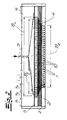
- the figures show a device for producing filaments, not shown, made of thermoplastic material.
- these filaments emerge from the spinneret orifices 1 of a spinneret plate 2 in a plurality of filament rows extending over a spun width B e .
- the plastic melt for the researchersspinnenden filaments is first supplied from a not shown extruder via a spinning pump, also not shown, a supply channel 3.
- the feed channel 3 opens into a distributor 4, which in the exemplary embodiment (FIGS. 1 and 2) is designed as a clothes hanger distributor and is provided for distributing the supplied plastic melt to a preliminary spun width B v .
- this distribution device 4 has the shape of a hanger with a subsequent choke field in section, so that a gradual broadening takes place up to the provisional Ausspinnumble B v .
- the distribution device 4 is first followed by a perforated plate 5 (filter plate or filter support plate) which has hole channels 6 distributed over the preliminary spun width B v for the plastic melt and serves to support a filter 11.
- a perforated plate 5 is also called "screen support plate” in English-speaking countries.
- the distribution device 4 or the perforated plate 5 is followed by a respective package of replaceable distributor plates 7.
- the distributor plates 7 have distributor openings 8 for receiving the plastic melt.
- a row of distributor openings 8 can be seen for each distributor plate 7.
- the extent or the width of a row of distribution openings 8 defines for each distribution plate 7 a Ausspinnumble B i
- each distributor plate 7 in the direction transverse to the Ausspinnbreite a plurality of juxtaposed rows of distribution openings 8.
- FIG. 3 It can be seen in FIG. 3 that in the exemplary embodiment the distributor openings 8 of adjacent rows of a distributor plate 7 are arranged offset from one another.
- each distributor plate 7 has distribution channels 9 extending across the spooling width B i , each distributor channel 9 interconnecting the distributor openings 8 of a row.
- a distributor channel 9 directly adjoins an adjacent distributor plate 7.
- this adjacent distributor plate 7 forms a wall of the adjacent distributor channel 9.
- This distributor channel 9 connects As a result, in the preferred embodiment according to FIGS.
- the distributing device 4 is followed by a plurality of exchangeable distributor plates 7, wherein the spinning-out widths B i respectively formed by the distributor openings 8 of the individual distributor plates 7 increase from the distributor 4 to the spinneret plate 2.
- the preliminary Ausspinnbreite B v is extended or increased in this way to the final Ausspinnbreite B e .
- the Ausspinnbreite B i thus increases from distributor plate 7 to distributor plate 7 to the spinneret plate 2 towards.
- the distributor device 4 is likewise followed by a plurality of exchangeable distributor plates 7, wherein the spinning-out widths B i formed by the distributor openings 8 of the individual distributor plates 7 decrease from the distributor 4 to the spinneret plate 2.
- the preliminary Ausspinnbreite B v is here reduced or reduced in this way to the final Ausspinnbreite B e .
- the Ausspinnbreite B i is thus reduced here from distributor plate 7 to distributor plate 7 to the spinneret plate 2 out.
- FIGS. 1 and 2 it can be seen that all Distribution openings 8 and distribution channels 9 in flow communication stand together and that in the operation of Device always all distribution openings 8 and distribution channels 9 flows through the plastic melt or be flushed through.
- the device according to the invention works without any shutdown of different Device segments.
- each heating zone H i is expediently associated with at least one heating device which is separately adjustable.
Landscapes
- Engineering & Computer Science (AREA)
- Mechanical Engineering (AREA)
- Textile Engineering (AREA)
- Spinning Methods And Devices For Manufacturing Artificial Fibers (AREA)
- Yarns And Mechanical Finishing Of Yarns Or Ropes (AREA)
- Inorganic Fibers (AREA)
- Nonwoven Fabrics (AREA)
Description
wobei eine Verteilvorrichtung zur Verteilung einer zugeführten Kunststoffschmelze auf eine vorläufige Ausspinnbreite vorgesehen ist,
wobei der Verteilvorrichtung zumindest eine austauschbare Verteilerplatte mit einer Mehrzahl von über die Ausspinnbreite verteilten Verteileröffnungen nachgeschaltet ist, welche Verteileröffnungen zur Aufnahme der Kunststoffschmelze aus der Verteilvorrichtung vorgesehen sind,
wobei der Verteilerplatte die austauschbare Spinndüsenplatte nachgeschaltet ist, welche Spinndüsenplatte über eine endgültige Ausspinnbreite verteilte Spinndüsenkanäle mit den zugeordneten Spinndüsenöffnungen aufweist
und wobei die von den Verteileröffnungen gebildete Ausspinnbreite geringer ist oder größer ist als die vorläufige Ausspinnbreite und wobei mit Hilfe der Verteilerplatte die vorläufige Ausspinnbreite auf die endgültige Ausspinnbreite reduziert oder erweitert wird und durch Auswechseln der Verteilerplatte die gewünschte endgültige Ausspinnbreite einstellbar ist.
- Fig. 1
- einen Schnitt durch eine erfindungsgemäße Vorrichtung in einem ersten Betriebszustand,
- Fig. 2
- den Gegenstand nach Fig. 1 in einem zweiten Betriebszustand,
- Fig. 3
- eine erfindungsgemäße Verteilerplatte und
- Fig. 4
- eine Spinndüsenplatte für die erfindungsgemäße Vorrichtung.
Claims (9)
- Vorrichtung zur Herstellung von Filamenten insbesondere aus thermoplastischem Kunststoff, wobei die Filamente in zumindest einer sich über die Ausspinnbreite erstreckenden Filamentreihe aus den Spinndüsenöffnungen (1) einer Spinndüsenplatte (2) austreten,
wobei eine Verteilvorrichtung (4) zur Verteilung einer zugeführten Kunststoffschmelze auf eine vorläufige Ausspinnbreite Bv vorgesehen ist,
wobei der Verteilvorrichtung (4) zumindest eine austauschbare Verteilerplatte (7) mit einer Mehrzahl von über die Ausspinnbreite Bi verteilten Verteileröffnungen (8) nachgeschaltet ist, welche Verteileröffnungen (8) zur Aufnahme der Kunststoffschmelze aus der Verteilvorrichtung (4) vorgesehen sind,
wobei der Verteilerplatte (7) die austauschbare Spinndüsenplatte (2) nachgeschaltet ist, welche Spinndüsenplatte (2) über eine endgültige Ausspinnbreite Be verteilte Spinndüsenkanäle (10) mit den zugeordneten Spinndüsenöffnungen (1) aufweist und
wobei die von den Verteileröffnungen (8) gebildete Ausspinnbreite Bi geringer ist oder größer als die vorläufige Ausspinnbreite Bv und wobei mit Hilfe der Verteilerplatte (7) die vorläufige Ausspinnbreite Bv auf die endgültige Ausspinnbreite Be reduziert oder erweitert wird und durch Auswechseln der Verteilerplatten (7) die gewünschte endgültige Ausspinnbreite Be einstellbar ist. - Vorrichtung nach Anspruch 1, wobei die Verteilvorrichtung (4) ein Kleiderbügelverteiler ist.
- Vorrichtung nach einem der Ansprüche 1 oder 2, wobei der Verteilvorrichtung (4) eine Mehrzahl von austauschbaren Verteilerplatten (7) nachgeschaltet ist und wobei die von den Verteileröffnungen (8) der einzelnen Verteilerplatten (7) jeweils gebildeten Ausspinnbreiten Bi von der Verteilvorrichtung (4) zur Spinndüsenplatte (2) hin abnehmen und die vorläufige Ausspinnbreite Bv auf diese Weise zur endgültigen Ausspinnbreite Be reduziert wird.
- Vorrichtung nach einem der Ansprüche 1 oder 2, wobei der Verteilvorrichtung (4) eine Mehrzahl von austauschbaren Verteilerplatten (7) nachgeschaltet ist, wobei die von den Verteileröffnungen (8) der einzelnen Verteilerplatten (7) jeweils gebildeten Ausspinnbreiten Bi von der Verteilvorrichtung (4) zur Spinndüsenplatte (2) hin zunehmen und die vorläufige Ausspinnbreite Bv auf diese Weise zur endgültigen Ausspinnbreite Be erweitert wird.
- Vorrichtung nach einem der Ansprüche 1 bis 4, wobei die Verteileröffnungen (8) übereinander angeordneter benachbarter Verteilerplatten (7) bezüglich der Ausspinnbreite Bi versetzt zueinander angeordnet sind.
- Vorrichtung nach einem der Ansprüche 1 bis 5, wobei eine Verteilerplatte (7) zumindest einen sich über zumindest einen Teil der Ausspinnbreite Bi erstreckenden Verteilerkanal (9) aufweist, welcher Verteilerkanal (9) zumindest einen Teil der Verteileröffnungen (8) miteinander verbindet.
- Vorrichtung nach einem der Ansprüche 1 bis 6, wobei eine Verteilerplatte (7) mehrere nebeneinander angeordnete Reihen von Verteileröffnungen (8) aufweist.
- Vorrichtung nach einem der Ansprüche 1 bis 7, wobei zwischen der Verteilvorrichtung (4) und einer Verteilerplatte (7) eine Lochplatte (5) mit Lochkanälen (6) für die Kunststoffschmelze zwischengeschaltet ist.
- Vorrichtung nach einem der Ansprüche 1 bis 8, wobei über die Breite der Verteilvorrichtung (4) eine Mehrzahl von Heizzonen (Hi) für die Verteilvorrichtung (4) vorgesehen ist, welche Heizzonen (Hi) jeweils separat beheizbar sind.
Priority Applications (15)
| Application Number | Priority Date | Filing Date | Title |
|---|---|---|---|
| DE50301678T DE50301678D1 (de) | 2003-06-13 | 2003-06-13 | Vorrichtung zur Herstellung von Filamenten |
| EP03013506A EP1486591B1 (de) | 2003-06-13 | 2003-06-13 | Vorrichtung zur Herstellung von Filamenten |
| AT03013506T ATE310114T1 (de) | 2003-06-13 | 2003-06-13 | Vorrichtung zur herstellung von filamenten |
| DK03013506T DK1486591T3 (da) | 2003-06-13 | 2003-06-13 | Anordning til fremstilling af filamenter |
| ES03013506T ES2252587T3 (es) | 2003-06-13 | 2003-06-13 | Dispositivo para la fabricacion de filamentos. |
| MYPI20041887A MY138121A (en) | 2003-06-13 | 2004-05-19 | Apparatus for the production of filaments |
| SA04250124A SA04250124B1 (ar) | 2003-06-13 | 2004-05-19 | جهاز لإنتاج شعيرات filaments |
| IL162386A IL162386A (en) | 2003-06-13 | 2004-06-07 | Device for the production of webs |
| JP2004169404A JP3953472B2 (ja) | 2003-06-13 | 2004-06-08 | 繊維を製造する装置 |
| CA002470558A CA2470558C (en) | 2003-06-13 | 2004-06-09 | Device for producing filaments |
| MXPA04005578A MXPA04005578A (es) | 2003-06-13 | 2004-06-09 | Aparato para producir filamentos. |
| US10/866,641 US7156639B2 (en) | 2003-06-13 | 2004-06-10 | Device for producing filaments |
| KR1020040042492A KR100593656B1 (ko) | 2003-06-13 | 2004-06-10 | 필라멘트 제조용 장치 |
| CNB2004100490755A CN1322180C (zh) | 2003-06-13 | 2004-06-11 | 用于生产长丝的装置 |
| BRPI0402214-9A BRPI0402214B1 (pt) | 2003-06-13 | 2004-06-14 | Dispositivo para a produção de filamentos |
Applications Claiming Priority (1)
| Application Number | Priority Date | Filing Date | Title |
|---|---|---|---|
| EP03013506A EP1486591B1 (de) | 2003-06-13 | 2003-06-13 | Vorrichtung zur Herstellung von Filamenten |
Publications (2)
| Publication Number | Publication Date |
|---|---|
| EP1486591A1 EP1486591A1 (de) | 2004-12-15 |
| EP1486591B1 true EP1486591B1 (de) | 2005-11-16 |
Family
ID=33185895
Family Applications (1)
| Application Number | Title | Priority Date | Filing Date |
|---|---|---|---|
| EP03013506A Expired - Lifetime EP1486591B1 (de) | 2003-06-13 | 2003-06-13 | Vorrichtung zur Herstellung von Filamenten |
Country Status (15)
| Country | Link |
|---|---|
| US (1) | US7156639B2 (de) |
| EP (1) | EP1486591B1 (de) |
| JP (1) | JP3953472B2 (de) |
| KR (1) | KR100593656B1 (de) |
| CN (1) | CN1322180C (de) |
| AT (1) | ATE310114T1 (de) |
| BR (1) | BRPI0402214B1 (de) |
| CA (1) | CA2470558C (de) |
| DE (1) | DE50301678D1 (de) |
| DK (1) | DK1486591T3 (de) |
| ES (1) | ES2252587T3 (de) |
| IL (1) | IL162386A (de) |
| MX (1) | MXPA04005578A (de) |
| MY (1) | MY138121A (de) |
| SA (1) | SA04250124B1 (de) |
Families Citing this family (18)
| Publication number | Priority date | Publication date | Assignee | Title |
|---|---|---|---|---|
| DE102005053248B4 (de) * | 2005-11-08 | 2016-12-01 | Axel Nickel | Schmelzblaskopf mit veränderbarer Spinnbreite |
| WO2007131714A2 (de) * | 2006-05-11 | 2007-11-22 | Oerlikon Textile Gmbh & Co. Kg | Vorrichtung zum schmelzspinnen einer reihenförmigen filamentschar |
| EP2660369B1 (de) * | 2010-12-27 | 2016-05-18 | Toray Industries, Inc. | Zusammengesetzte spinndüse und verfahren zur herstellung von verbundfasern |
| CN102154719B (zh) * | 2011-04-21 | 2012-05-23 | 苏州龙杰特种纤维股份有限公司 | 一种异截面异收缩涤纶长丝的制造方法 |
| GB201202565D0 (en) | 2012-02-15 | 2012-03-28 | British American Tobacco Co | Packaging |
| CN103320874A (zh) * | 2013-05-31 | 2013-09-25 | 吉铨精密机械(苏州)有限公司 | 一种丝股铸带头的分配板 |
| CN104294380B (zh) * | 2014-09-29 | 2017-02-22 | 山东泰鹏环保材料股份有限公司 | 大狭缝涤纶无纺布可调幅宽生产线 |
| CN105200535A (zh) * | 2015-10-23 | 2015-12-30 | 天津市静海县远大工贸有限公司 | 一种可大幅增产的多排孔纺丝喷头 |
| CN106346737B (zh) * | 2016-08-25 | 2019-03-26 | 凯迈(洛阳)机电有限公司 | 一种铸带头组件及铸带头 |
| KR102109674B1 (ko) * | 2018-11-06 | 2020-05-28 | 주식회사 휴비스 | 원사 균일성이 개선된 방사팩 |
| CN109382996B (zh) * | 2018-12-05 | 2024-04-30 | 无锡会通轻质材料股份有限公司 | 一种中空epp珠粒挤出机构 |
| CN111088530A (zh) * | 2020-01-04 | 2020-05-01 | 湖州欣久利机械有限公司 | 一种热熔胶网膜生产用喷丝板 |
| DE102020001132A1 (de) * | 2020-02-20 | 2021-08-26 | Oerlikon Textile Gmbh & Co. Kg | Schmelzblasdüsenvorrichtung |
| TW202138647A (zh) | 2020-02-24 | 2021-10-16 | 奧地利商蘭仁股份有限公司 | 用於製造紡絲黏合不織布之方法 |
| TW202146719A (zh) | 2020-02-24 | 2021-12-16 | 奧地利商蘭仁股份有限公司 | 用於製造紡絲黏合不織布之方法 |
| DE102022134399A1 (de) | 2022-12-21 | 2024-06-27 | Reifenhäuser GmbH & Co. KG Maschinenfabrik | Vorrichtung zur Herstellung von Filamenten |
| JP2024089635A (ja) * | 2022-12-21 | 2024-07-03 | ライフェンホイザー・ゲゼルシャフト・ミト・ベシュレンクテル・ハフツング・ウント・コンパニー・コマンデイトゲゼルシャフト・マシイネンファブリーク | フィラメントを製造するための装置 |
| EP4389946B1 (de) | 2022-12-21 | 2025-02-12 | Reifenhäuser GmbH & Co. KG Maschinenfabrik | Vorrichtung zur herstellung von filamenten |
Family Cites Families (11)
| Publication number | Priority date | Publication date | Assignee | Title |
|---|---|---|---|---|
| JPS62156306A (ja) * | 1985-12-27 | 1987-07-11 | Chisso Corp | 複合紡糸用口金装置 |
| US4743191A (en) * | 1987-04-02 | 1988-05-10 | Allied-Signal Inc. | Multi-piece die for forming honeycomb structures |
| US5162074A (en) * | 1987-10-02 | 1992-11-10 | Basf Corporation | Method of making plural component fibers |
| US5147197A (en) * | 1990-12-26 | 1992-09-15 | Basf Corporation | Sealing plate for a spinnerette assembly |
| US5397227A (en) * | 1990-12-26 | 1995-03-14 | Basf Corporation | Apparatus for changing both number and size of filaments |
| CA2107930C (en) * | 1992-10-29 | 2000-07-11 | John A. Hodan | Flow distribution plates |
| DE4312419C2 (de) * | 1993-04-16 | 1996-02-22 | Reifenhaeuser Masch | Anlage für die Herstellung einer Spinnvliesbahn aus aerodynamischen verstreckten Filamenten aus Kunststoff |
| DE4417815C1 (de) * | 1994-05-20 | 1995-10-12 | Inventa Ag | Filter für Polymerlösungen und Polymerschmelzen |
| CN2216070Y (zh) * | 1994-12-30 | 1995-12-27 | 侯慕毅 | 模块组合式宽体喷丝机头 |
| US5935291A (en) * | 1997-10-29 | 1999-08-10 | Ppg Industries Ohio, Inc. | Bushings and fiber forming assemblies |
| ATE331057T1 (de) * | 2001-10-18 | 2006-07-15 | Fiber Innovation Technology | Vorrichtung und verfahren zum spinnen von synthetischen fasern |
-
2003
- 2003-06-13 DK DK03013506T patent/DK1486591T3/da active
- 2003-06-13 DE DE50301678T patent/DE50301678D1/de not_active Expired - Lifetime
- 2003-06-13 ES ES03013506T patent/ES2252587T3/es not_active Expired - Lifetime
- 2003-06-13 AT AT03013506T patent/ATE310114T1/de not_active IP Right Cessation
- 2003-06-13 EP EP03013506A patent/EP1486591B1/de not_active Expired - Lifetime
-
2004
- 2004-05-19 SA SA04250124A patent/SA04250124B1/ar unknown
- 2004-05-19 MY MYPI20041887A patent/MY138121A/en unknown
- 2004-06-07 IL IL162386A patent/IL162386A/en active IP Right Grant
- 2004-06-08 JP JP2004169404A patent/JP3953472B2/ja not_active Expired - Fee Related
- 2004-06-09 CA CA002470558A patent/CA2470558C/en not_active Expired - Lifetime
- 2004-06-09 MX MXPA04005578A patent/MXPA04005578A/es active IP Right Grant
- 2004-06-10 KR KR1020040042492A patent/KR100593656B1/ko not_active Expired - Lifetime
- 2004-06-10 US US10/866,641 patent/US7156639B2/en not_active Expired - Lifetime
- 2004-06-11 CN CNB2004100490755A patent/CN1322180C/zh not_active Expired - Lifetime
- 2004-06-14 BR BRPI0402214-9A patent/BRPI0402214B1/pt not_active IP Right Cessation
Also Published As
| Publication number | Publication date |
|---|---|
| BRPI0402214B1 (pt) | 2014-04-29 |
| MY138121A (en) | 2009-04-30 |
| CN1572918A (zh) | 2005-02-02 |
| JP2005002549A (ja) | 2005-01-06 |
| CA2470558C (en) | 2009-08-18 |
| SA04250124B1 (ar) | 2007-04-03 |
| US7156639B2 (en) | 2007-01-02 |
| ES2252587T3 (es) | 2006-05-16 |
| KR20040107382A (ko) | 2004-12-20 |
| CN1322180C (zh) | 2007-06-20 |
| IL162386A (en) | 2009-11-18 |
| DK1486591T3 (da) | 2006-03-27 |
| BRPI0402214A (pt) | 2005-01-25 |
| MXPA04005578A (es) | 2005-03-23 |
| EP1486591A1 (de) | 2004-12-15 |
| DE50301678D1 (de) | 2005-12-22 |
| KR100593656B1 (ko) | 2006-06-30 |
| US20040265415A1 (en) | 2004-12-30 |
| CA2470558A1 (en) | 2004-12-13 |
| ATE310114T1 (de) | 2005-12-15 |
| JP3953472B2 (ja) | 2007-08-08 |
Similar Documents
| Publication | Publication Date | Title |
|---|---|---|
| EP1486591B1 (de) | Vorrichtung zur Herstellung von Filamenten | |
| DE69425537T2 (de) | Schmelzblasdüse | |
| DE69331102T2 (de) | Tieffilterpatrone und methode und vorrichtung zu deren herstellung | |
| DE69637297T2 (de) | Verfahren und vorrichtung zur vliesstoffherstellung | |
| EP3088585B1 (de) | Verfahren und vorrichtung zur herstellung eines spinnvlieses aus filamenten und spinnvlies | |
| EP2016210B1 (de) | Vorrichtung zum schmelzspinnen einer reihenförmigen filamentschar | |
| EP3692188B1 (de) | Vorrichtung für die extrusion von filamenten und herstellung von spinnvliesstoffen | |
| DE69512804T2 (de) | Schnellspinnen von Mehrkomponentenfasern mit hochperforierten Spinndüsen und Kühlung mit hoher Geschwindigkeit | |
| DE3685730T2 (de) | Spinnvorrichtung zum spinnen von verbundfaeden. | |
| DE112005002619T5 (de) | Schmelzgeblasene nicht gewebte Stoffe einschließlich Nanofasern und Vorrichtung und Verfahren zum Bilden solcher schmelzgeblasener nicht gewebter Stoffe | |
| DE60120260T2 (de) | Verfahren zur Herstellung eines Vliesstoffes und zugehörige Vorrichtung | |
| DE4040242A1 (de) | Verfahren und vorrichtung zur herstellung von feinstfasern aus thermoplastischen polymeren | |
| EP1902164A1 (de) | Spinnvorrichtung zur erzeugung feiner fäden durch spleissen | |
| DE19750724C2 (de) | Vorrichtung zum Herstellen eines Spinnvlieses aus Kern-Mantel-Struktur aufweisenden Bikomponentenfäden | |
| DE102005053248B4 (de) | Schmelzblaskopf mit veränderbarer Spinnbreite | |
| EP1340844B1 (de) | Meltblown-Anlage | |
| EP1512777B1 (de) | Vorrichtung zur Erzeugung von Mehrkomponentenfasern, insbesondere von Bikomponentenfasern | |
| DE2532900A1 (de) | Verfahren zur herstellung von spinnvliesen | |
| EP4123063B1 (de) | Düsenkopf zur erzeugung von filamenten | |
| EP4493386A1 (de) | Filtriervorrichtung zum filtrieren eines fluids sowie betreffendes betriebsverfahren | |
| DE60105768T2 (de) | Anlage bestimmt für die herstellung von thermoplastischen geschnittenen fasern | |
| DE102007032107A1 (de) | Vorrichtung zum Schmelzspinnen einer reihenförmigen Filamentschar | |
| EP2057308A1 (de) | Verfahren und vorrichtung zum ablegen synthetischer fasern zu einem vlies | |
| DE102011011790A1 (de) | Vorrichtung zum Extrudieren und Abkühlen einer Vielzahl von Monofilamenten | |
| DE102004038462A1 (de) | Spinnkopf |
Legal Events
| Date | Code | Title | Description |
|---|---|---|---|
| PUAI | Public reference made under article 153(3) epc to a published international application that has entered the european phase |
Free format text: ORIGINAL CODE: 0009012 |
|
| 17P | Request for examination filed |
Effective date: 20040225 |
|
| AK | Designated contracting states |
Kind code of ref document: A1 Designated state(s): AT BE BG CH CY CZ DE DK EE ES FI FR GB GR HU IE IT LI LU MC NL PT RO SE SI SK TR |
|
| AX | Request for extension of the european patent |
Extension state: AL LT LV MK |
|
| GRAP | Despatch of communication of intention to grant a patent |
Free format text: ORIGINAL CODE: EPIDOSNIGR1 |
|
| GRAS | Grant fee paid |
Free format text: ORIGINAL CODE: EPIDOSNIGR3 |
|
| AKX | Designation fees paid |
Designated state(s): AT BE BG CH CY CZ DE DK EE ES FI FR GB GR HU IE IT LI LU MC NL PT RO SE SI SK TR |
|
| GRAA | (expected) grant |
Free format text: ORIGINAL CODE: 0009210 |
|
| RAP1 | Party data changed (applicant data changed or rights of an application transferred) |
Owner name: REIFENHAEUSER GMBH & CO. KG MASCHINENFABRIK |
|
| AK | Designated contracting states |
Kind code of ref document: B1 Designated state(s): AT BE BG CH CY CZ DE DK EE ES FI FR GB GR HU IE IT LI LU MC NL PT RO SE SI SK TR |
|
| PG25 | Lapsed in a contracting state [announced via postgrant information from national office to epo] |
Ref country code: NL Free format text: LAPSE BECAUSE OF FAILURE TO SUBMIT A TRANSLATION OF THE DESCRIPTION OR TO PAY THE FEE WITHIN THE PRESCRIBED TIME-LIMIT Effective date: 20051116 Ref country code: SI Free format text: LAPSE BECAUSE OF FAILURE TO SUBMIT A TRANSLATION OF THE DESCRIPTION OR TO PAY THE FEE WITHIN THE PRESCRIBED TIME-LIMIT Effective date: 20051116 Ref country code: FI Free format text: LAPSE BECAUSE OF FAILURE TO SUBMIT A TRANSLATION OF THE DESCRIPTION OR TO PAY THE FEE WITHIN THE PRESCRIBED TIME-LIMIT Effective date: 20051116 Ref country code: RO Free format text: LAPSE BECAUSE OF FAILURE TO SUBMIT A TRANSLATION OF THE DESCRIPTION OR TO PAY THE FEE WITHIN THE PRESCRIBED TIME-LIMIT Effective date: 20051116 Ref country code: SK Free format text: LAPSE BECAUSE OF FAILURE TO SUBMIT A TRANSLATION OF THE DESCRIPTION OR TO PAY THE FEE WITHIN THE PRESCRIBED TIME-LIMIT Effective date: 20051116 Ref country code: IE Free format text: LAPSE BECAUSE OF FAILURE TO SUBMIT A TRANSLATION OF THE DESCRIPTION OR TO PAY THE FEE WITHIN THE PRESCRIBED TIME-LIMIT Effective date: 20051116 |
|
| REG | Reference to a national code |
Ref country code: GB Ref legal event code: FG4D Free format text: NOT ENGLISH |
|
| REG | Reference to a national code |
Ref country code: CH Ref legal event code: EP |
|
| REF | Corresponds to: |
Ref document number: 50301678 Country of ref document: DE Date of ref document: 20051222 Kind code of ref document: P |
|
| REG | Reference to a national code |
Ref country code: IE Ref legal event code: FG4D Free format text: LANGUAGE OF EP DOCUMENT: GERMAN |
|
| PG25 | Lapsed in a contracting state [announced via postgrant information from national office to epo] |
Ref country code: SE Free format text: LAPSE BECAUSE OF FAILURE TO SUBMIT A TRANSLATION OF THE DESCRIPTION OR TO PAY THE FEE WITHIN THE PRESCRIBED TIME-LIMIT Effective date: 20060216 Ref country code: BG Free format text: LAPSE BECAUSE OF FAILURE TO SUBMIT A TRANSLATION OF THE DESCRIPTION OR TO PAY THE FEE WITHIN THE PRESCRIBED TIME-LIMIT Effective date: 20060216 |
|
| GBT | Gb: translation of ep patent filed (gb section 77(6)(a)/1977) |
Effective date: 20060201 |
|
| REG | Reference to a national code |
Ref country code: DK Ref legal event code: T3 |
|
| PG25 | Lapsed in a contracting state [announced via postgrant information from national office to epo] |
Ref country code: PT Free format text: LAPSE BECAUSE OF FAILURE TO SUBMIT A TRANSLATION OF THE DESCRIPTION OR TO PAY THE FEE WITHIN THE PRESCRIBED TIME-LIMIT Effective date: 20060417 |
|
| NLV1 | Nl: lapsed or annulled due to failure to fulfill the requirements of art. 29p and 29m of the patents act | ||
| REG | Reference to a national code |
Ref country code: GR Ref legal event code: EP Ref document number: 20060400502 Country of ref document: GR |
|
| REG | Reference to a national code |
Ref country code: ES Ref legal event code: FG2A Ref document number: 2252587 Country of ref document: ES Kind code of ref document: T3 |
|
| PG25 | Lapsed in a contracting state [announced via postgrant information from national office to epo] |
Ref country code: HU Free format text: LAPSE BECAUSE OF FAILURE TO SUBMIT A TRANSLATION OF THE DESCRIPTION OR TO PAY THE FEE WITHIN THE PRESCRIBED TIME-LIMIT Effective date: 20060517 |
|
| REG | Reference to a national code |
Ref country code: IE Ref legal event code: FD4D |
|
| PG25 | Lapsed in a contracting state [announced via postgrant information from national office to epo] |
Ref country code: MC Free format text: LAPSE BECAUSE OF NON-PAYMENT OF DUE FEES Effective date: 20060630 Ref country code: BE Free format text: LAPSE BECAUSE OF NON-PAYMENT OF DUE FEES Effective date: 20060630 |
|
| ET | Fr: translation filed | ||
| PLBE | No opposition filed within time limit |
Free format text: ORIGINAL CODE: 0009261 |
|
| STAA | Information on the status of an ep patent application or granted ep patent |
Free format text: STATUS: NO OPPOSITION FILED WITHIN TIME LIMIT |
|
| 26N | No opposition filed |
Effective date: 20060817 |
|
| PG25 | Lapsed in a contracting state [announced via postgrant information from national office to epo] |
Ref country code: AT Free format text: LAPSE BECAUSE OF NON-PAYMENT OF DUE FEES Effective date: 20060613 |
|
| BERE | Be: lapsed |
Owner name: REIFENHAUSER G.M.B.H. & CO. KG MASCHINENFABRIK Effective date: 20060630 |
|
| REG | Reference to a national code |
Ref country code: CH Ref legal event code: PL |
|
| PG25 | Lapsed in a contracting state [announced via postgrant information from national office to epo] |
Ref country code: LI Free format text: LAPSE BECAUSE OF NON-PAYMENT OF DUE FEES Effective date: 20070630 Ref country code: CH Free format text: LAPSE BECAUSE OF NON-PAYMENT OF DUE FEES Effective date: 20070630 |
|
| PG25 | Lapsed in a contracting state [announced via postgrant information from national office to epo] |
Ref country code: EE Free format text: LAPSE BECAUSE OF FAILURE TO SUBMIT A TRANSLATION OF THE DESCRIPTION OR TO PAY THE FEE WITHIN THE PRESCRIBED TIME-LIMIT Effective date: 20051116 |
|
| PG25 | Lapsed in a contracting state [announced via postgrant information from national office to epo] |
Ref country code: LU Free format text: LAPSE BECAUSE OF NON-PAYMENT OF DUE FEES Effective date: 20060613 |
|
| PG25 | Lapsed in a contracting state [announced via postgrant information from national office to epo] |
Ref country code: CY Free format text: LAPSE BECAUSE OF FAILURE TO SUBMIT A TRANSLATION OF THE DESCRIPTION OR TO PAY THE FEE WITHIN THE PRESCRIBED TIME-LIMIT Effective date: 20051116 |
|
| REG | Reference to a national code |
Ref country code: FR Ref legal event code: PLFP Year of fee payment: 14 |
|
| REG | Reference to a national code |
Ref country code: FR Ref legal event code: PLFP Year of fee payment: 15 |
|
| REG | Reference to a national code |
Ref country code: FR Ref legal event code: PLFP Year of fee payment: 16 |
|
| PGFP | Annual fee paid to national office [announced via postgrant information from national office to epo] |
Ref country code: GB Payment date: 20220625 Year of fee payment: 20 Ref country code: DK Payment date: 20220624 Year of fee payment: 20 Ref country code: CZ Payment date: 20220530 Year of fee payment: 20 |
|
| PGFP | Annual fee paid to national office [announced via postgrant information from national office to epo] |
Ref country code: TR Payment date: 20220609 Year of fee payment: 20 Ref country code: GR Payment date: 20220627 Year of fee payment: 20 |
|
| PGFP | Annual fee paid to national office [announced via postgrant information from national office to epo] |
Ref country code: FR Payment date: 20220625 Year of fee payment: 20 |
|
| PGFP | Annual fee paid to national office [announced via postgrant information from national office to epo] |
Ref country code: IT Payment date: 20220630 Year of fee payment: 20 Ref country code: ES Payment date: 20220701 Year of fee payment: 20 Ref country code: DE Payment date: 20220628 Year of fee payment: 20 |
|
| REG | Reference to a national code |
Ref country code: DE Ref legal event code: R071 Ref document number: 50301678 Country of ref document: DE |
|
| REG | Reference to a national code |
Ref country code: DK Ref legal event code: EUP Expiry date: 20230613 |
|
| REG | Reference to a national code |
Ref country code: ES Ref legal event code: FD2A Effective date: 20230626 |
|
| REG | Reference to a national code |
Ref country code: GB Ref legal event code: PE20 Expiry date: 20230612 |
|
| PG25 | Lapsed in a contracting state [announced via postgrant information from national office to epo] |
Ref country code: ES Free format text: LAPSE BECAUSE OF EXPIRATION OF PROTECTION Effective date: 20230614 Ref country code: CZ Free format text: LAPSE BECAUSE OF EXPIRATION OF PROTECTION Effective date: 20230613 |
|
| PG25 | Lapsed in a contracting state [announced via postgrant information from national office to epo] |
Ref country code: GB Free format text: LAPSE BECAUSE OF EXPIRATION OF PROTECTION Effective date: 20230612 |