EP1486447A1 - Hülsenteller für einen Spulenrahmen - Google Patents
Hülsenteller für einen Spulenrahmen Download PDFInfo
- Publication number
- EP1486447A1 EP1486447A1 EP03013197A EP03013197A EP1486447A1 EP 1486447 A1 EP1486447 A1 EP 1486447A1 EP 03013197 A EP03013197 A EP 03013197A EP 03013197 A EP03013197 A EP 03013197A EP 1486447 A1 EP1486447 A1 EP 1486447A1
- Authority
- EP
- European Patent Office
- Prior art keywords
- sleeve plate
- clamping ring
- base body
- sleeve
- plate according
- Prior art date
- Legal status (The legal status is an assumption and is not a legal conclusion. Google has not performed a legal analysis and makes no representation as to the accuracy of the status listed.)
- Withdrawn
Links
Images


Classifications
-
- B—PERFORMING OPERATIONS; TRANSPORTING
- B65—CONVEYING; PACKING; STORING; HANDLING THIN OR FILAMENTARY MATERIAL
- B65H—HANDLING THIN OR FILAMENTARY MATERIAL, e.g. SHEETS, WEBS, CABLES
- B65H54/00—Winding, coiling, or depositing filamentary material
- B65H54/02—Winding and traversing material on to reels, bobbins, tubes, or like package cores or formers
- B65H54/40—Arrangements for rotating packages
- B65H54/54—Arrangements for supporting cores or formers at winding stations; Securing cores or formers to driving members
- B65H54/553—Both-ends supporting arrangements
-
- B—PERFORMING OPERATIONS; TRANSPORTING
- B65—CONVEYING; PACKING; STORING; HANDLING THIN OR FILAMENTARY MATERIAL
- B65H—HANDLING THIN OR FILAMENTARY MATERIAL, e.g. SHEETS, WEBS, CABLES
- B65H2701/00—Handled material; Storage means
- B65H2701/30—Handled filamentary material
- B65H2701/31—Textiles threads or artificial strands of filaments
Definitions
- the invention relates to a sleeve plate for a Spool frame of a textile machine producing cross-wound bobbins according to the preamble of claim 1.
- a sleeve plate which has a cylindrical centering projection, the largest outer diameter of which is somewhat smaller than the smallest inner diameter of the sleeve.
- the sleeve of the cross-wound bobbin held in the bobbin frame is fixed essentially over its end faces between radially projecting contact surfaces of the bobbin plate. This means that there is usually some play between the inside diameter of the sleeve and the outside diameter of the centering shoulder of the sleeve plate.
- This tolerance-related play between the sleeve plate and sleeve does have advantages if, as described in the subsequently published DE 101 39 072.6, a new thread is to be fixed between the sleeve plate and an end face of the sleeve when re-spinning a job, and the sleeve plate by a so-called sleeve plate opener Service unit is easily folded so that a strand of thread can be fixed in the resulting gap.
- the core plate rotates constantly relative to the core, which among other things leads to significant wear of the core plate and occasionally to wear through of the fixed thread, with the possible consequence that the thread reserve unwinds.
- the game between the sleeve and the sleeve plate prevents the transmission of coil vibrations to the coil frame, which are then often poorly absorbed by the vibration damper of the coil frame, which leads to spools of poorer quality with certain fiber materials.
- the play between the sleeve and the centering shoulder of the sleeve plate also has a negative effect in the production of cross-wound bobbins with, for example, step precision winding, since in this case the winding unit computer requires the exact bobbin speed.
- the coil speed can generally be determined in a simple manner using a Hall sensor on the coil frame and one or more magnets on the sleeve plate. In this case, however, the sleeve plate must rotate exactly at the speed of the spool, that is, no slippage may occur between the sleeve plate and the sleeve.
- This known sleeve plate has conical sleeve receptacles, the large outside diameter of which is clearly above the inside diameter of the sleeves. This means that the sleeve is centered and fixed directly by the conical sleeve receptacles.
- Such sleeve plates are disadvantageous, however, if a job is to be spun on again according to the method described in DE 101 39 072.6. Specifically for fixing the new thread between the face of the tube and the tube plate, these known tube plates are hardly suitable, since such a tube plate, when it is pivoted and tilted to pinch the thread, then no longer aligns reliably with the axis of rotation of the tube. Rather, such a sleeve plate subsequently carries out a wobbling movement when winding a thread.
- the sleeve plate according to DE 38 37 337 C2 therefore have spiral-like grooves for fixing a new thread, which should pull the thread under the sleeve and fix it there. In practice, however, this known method has not proven to be sufficiently reliable.
- the Invention the task of a sleeve plate develop, on the one hand, a slip-free contact guaranteed between the sleeve plate and the sleeve of the cheese is, on the other hand, when re-piecing a job Thread can be easily attached to the sleeve.
- the embodiment according to the invention has the particular advantage that the functions "clamp sleeves” and “clamp thread” are separate. This means that the sleeve positioned in the bobbin frame remains centered and free of play thanks to the tension cone of the base body, while the thread is securely fixed between the clamping ring and the face of the sleeve.
- the clamping cone of the base body has a plurality of radially arranged guide grooves on its circumference, in which the clamping ring is guided with corresponding guide webs.
- the spring element ensures that the Always keep the clamping ring flat on the face of the Sleeve which, as already mentioned above, between the Clamping cone of two sleeve plates is fixed, rests and one thread positioned between the clamping ring and the end face reliably stuck.
- travel limiting approaches are integrally formed on the back of the guide webs of the clamping ring. These path limiting approaches correspond to the radial stops on the bearing shoulder of the base body and thereby ensure that the axial movement of the clamping ring relative to the base body is limited.
- the spring element can also be positioned safely and functionally between the travel limitation approaches of the clamping ring and the bearing approach of the base body.
- the The subject of claim 5 is the clamping ring with the Base body connected via a spring element so that the Clamping ring on the one hand with respect to the central axis of the Sleeve plate is swinging, on the other hand during the Spool always lies flat on the end face of the sleeve.
- the base body is equipped on its outer circumference with guide lugs which correspond to radially arranged recesses in the clamping ring.
- the clamping ring is on the one hand rotatably connected on the other hand axially movably connected to the base body.
- the spring element is made of a highly elastic material, in particular rubber, and is provided with large-area connecting flanges.
- the spring element is fastened to the clamping ring with an outer flange and to the base body with an inner flange.
- spring element which is made of spring steel.
- the spring element is fixed to the base body with its inner flange, while the outer flange grips behind the clamping ring.
- Spring elements made of spring steel not only work very reliably, they are also characterized by a long service life. In addition, relatively high clamping forces can be achieved in a simple manner by means of such spring elements.
- the inner flange of the spring element is designed as a closed ring, as set out in claim 9, while the outer flange has a plurality of radially arranged lamellae.
- a spring element designed on the one hand can be securely fixed on the base body of the sleeve plate and on the other hand ensures high elasticity.
- the tensioning cone of the base body advantageously has two areas with different conicity.
- the area in front has a greater conicity, which makes it much easier to place the sleeve on the clamping cone.
- both the base body of the sleeve plate and the clamping ring are made of a plastic.
- the production is advantageously carried out according to the so-called injection molding or die casting process. In this way, the sleeve plates according to the invention can be manufactured inexpensively on the one hand, but still have the required long service life on the other hand.
- a bobbin frame 1 of a (not shown) cross-wound textile machine is indicated.
- the bobbin frame 1 is connected via a horizontal pivot axis 2 to the bobbin case 3 of one of the numerous workstations of the textile machine producing cross-wound bobbins.
- the coil frame 1 also has a second pivot axis 4 arranged orthogonally to the first pivot axis 2, which, if necessary, also enables the production of conical cross-wound bobbins.
- the bobbin frame 1 has two bobbin frame arms 5, 6 between which, freely rotatable, a cross-wound bobbin 7 is held.
- the bobbin frame arm 5 is part of the bobbin frame base frame, while the bobbin frame arm 6 is connected via a pivot axis 8 and can be pivoted outwards for receiving or dispensing a cross-wound bobbin 7.
- sleeve plates 9 are arranged for fixing and freely rotatable mounting of the sleeve 10 of the cheese.
- At least one of these sleeve plates 9 has the Training according to the invention, that is, it consists of a body with a clamping cone and one with respect to the Base body movably mounted clamping ring.
- FIG. 2 shows a first embodiment of the sleeve plate according to the invention.
- the sleeve plate 9 essentially consists of a base body 11 and a clamping ring 12 which is axially movably mounted with respect to the base body 11.
- the base body 11 of the sleeve plate 9 has a clamping cone 13 which has numerous radially arranged guide grooves 14 on its circumference.
- the clamping cone 13 preferably has at least two regions with different conicity. This means that the area 18 of the clamping cone 13 facing the sleeve 10 is followed by an area 19 with a lower conicity.
- the radial stops 16 form one Abutment for a spring element 20, preferably one Compression spring while the central pin 17 in the inner ring of a rolling bearing 21 engages.
- the outer ring of this rolling bearing 21st is, as indicated in FIG. 2, in a bearing pan 22 supported on one of the two coil frame arms 5,6 is set.
- the clamping ring 12 is provided with radially inwardly directed guide webs 23, which correspond to the guide grooves 14 in the clamping cone 13 of the base body 11. On the back of the guide webs 23 there are also molded-on limiters 24 which, in connection with the radial stops 16 of the base body 11, limit the axial movement of the clamping ring 12.
- FIG. 3 shows a further possible embodiment of a sleeve plate 9 according to the invention.
- This embodiment which, like the embodiments shown in FIGS. 4-6, has a somewhat narrower overall width, is essentially comparable to the sleeve plate according to FIG. 2. Corresponding components are therefore identified with the same reference numbers.
- the sleeve plate 9 has a base body 11 and one movable with respect to the base body 11 mounted clamping plate 12.
- the base body 11 is included the clamping plate 12 connected via a spring element 25, which a highly elastic material, such as rubber, is made.
- the spring element 25 is a Outer flange 35 and an inner flange 36 or corresponding Fastening means 28 both form-fitting on the base body 11 and also fixed on the clamping ring 12.
- the spring element 25 enables, for example, to insert a thread an axial displacement of the clamping ring 12 in a simple manner relative to the base body 11, preferably a tilting of the Clamping ring 12.
- the corresponding radial recesses 26 in the clamping ring 12 correspond, also ensure that the clamping ring 12th and the base body 11 are connected to one another in a rotationally fixed manner.
- thread positioning means 29 can be integrated into the clamping ring 12.
- These thread positioning means 29 each consist, for example, of a pin 30 arranged in a blind hole 31 or the like, which is acted upon, for example via a compression spring 32, in the direction of the sleeve 10.
- the pin 30 always rests on the end face of the sleeve 10 and thereby forms a defined contact surface for the thread 33 to be clamped, in particular in the case of thick-walled sleeve 10.
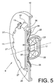
- Figures 5 and 6 show sleeve plate 9, which are slightly modified compared to the embodiment of Figure 3.
- These sleeve plates 9 differ from the sleeve plate 9 already described above, in particular in the design or the fixing of the spring element 25 connected between the base body 11 and the clamping plate 12.
- This means that these sleeve plates 9 have a spring element 25 which is made, for example, of spring steel.
- the spring element 25 has a closed inner flange 36 and a slotted outer flange 35.
- the outer flange 35 which has a plurality of radially arranged lamellae 38, which grip the clamping ring 12 in a force-fitting manner, is only fixed on the base body 11.
- the inner flange 36 of the spring element 25 is either, as indicated in FIG. 5, curved slightly to the rear and clamped between an annular extension of the base body 11 and the (not shown) inner ring of the roller bearing 21 above the inner flange 36 of the spring element 25 , as shown in Fig. 6, fixed by means of a spacer ring 37 between the base body 11 and the inner ring of the rolling bearing 21.
- the workplaces become packages manufacturing textile machines by automatically working Service units supplied, for example, along the Patrol workplaces of the textile machine and at Intervene as needed.
- the service unit positions itself at the relevant workstation and ensures that the finished cross-wound bobbin 7 is transferred to a cross-wound bobbin removal device and a new empty tube 10 in the bobbin frame 1 the place of work. That is, the new empty sleeve 10 is freely rotatable, fixed between the freely rotatable clamping cones 13 of the sleeve plate 9.
- the job is spun on again by means of an auxiliary thread provided by the service unit.
- the service unit Before or during the running thread, which is disposed of at this point in time by an in-house suction nozzle, is brought into the area of the bobbin frame 1 by a special thread laying device, the service unit applies a so-called core plate opener to the clamping ring 12 of the core plate 9 according to the invention and tilts it somewhat outward.
- the thread held ready in the thread laying device of the service unit as a thread tendon is securely fixed between the end face of the sleeve 10 and the clamping ring 12 of the sleeve plate 9 after the sleeve plate opener has been pulled back.
- the sleeve 10 is lowered onto the drive drum of the job and a new winding process is started.
Abstract
Description
Bei dieser Ausführungsform wird die Hülse der im Spulenrahmen gehaltenen Kreuzspule im wesentlichen über ihre Stirnseiten zwischen radial abstehenden Anlageflächen des Hülsentellers fixiert.
Das heißt, zwischen dem Innendurchmesser der Hülse und dem Außendurchmesser des Zentrieransatzes des Hülsentellers tritt in der Regel etwas Spiel auf.
Dieses toleranzbedingte Spiel zwischen Hülsenteller und Hülse hat zwar Vorteile, wenn, wie in der nachveröffentlichten DE 101 39 072.6 beschrieben, beim Wiederanspinnen einer Arbeitsstelle ein neuer Faden zwischen dem Hülsenteller und einer Stirnseite der Hülse festgelegt werden soll und dabei der Hülsenteller durch einen sogenannten Hülsentelleröffner eines Serviceaggregates leicht so angekantet wird, daß in dem entstandenen Spalt ein Fadenstrang festgelegt werden kann.
Außerdem wird durch das Spiel zwischen Hülse und Hülsenteller die Übertragung von Spulenschwingungen auf den Spulenrahmen behindert, die dann oft nur noch mangelhaft durch den Schwingungsdämpfer des Spulenrahmens absorbiert werden, was bei bestimmten Fasermaterialien zu Spulen mit einer schlechteren Qualität führt.
Die Spulendrehzahl kann in der Regel auf einfache Weise mit einem Hall-Sensor am Spulenrahmen und einem oder mehreren Magneten am Hülsenteller ermittelt werden. Der Hülsenteller muß in diesem Fall jedoch exakt mit der Drehzahl der Spule rotieren, das heißt, zwischen Hülsenteller und Hülse darf kein Schlupf auftreten.
Das heißt, bei diesem Hülsenteller wird die Hülse direkt durch die konischen Hülsenaufnahmen zentriert und fixiert.
Ein derartiger Hülsenteller führt vielmehr anschließend beim Aufspulen eines Fadens eine taumelnde Bewegung aus.
Die Hülsenteller gemäß DE 38 37 337 C2 weisen daher zum Festlegen eines neuen Fadens spiralartige Nuten auf, die den Faden unter die Hülse ziehen und dort festlegen sollen.
Diese bekannte Methode hat sich in der Praxis allerdings als nicht ausreichend zuverlässig erwiesen.
Das heißt, die im Spulenrahmen positionierte Hülse bleibt durch den Spannkonus des Grundkörpers spielfrei und zentrisch fixiert, während der Faden zwischen dem Klemmring und der Hülsenstirnseite sicher festgelegt wird.
In die dabei zwischen Hülsenstirnseite und Klemmring entstehende Lücke kann anschließend der zu befestigende Faden eingelegt und durch Zurückkippen des Klemmringes fixiert werden.
Zwischen den Wegbegrenzungsansätzen des Klemmringes und dem Lageransatz des Grundkörpers ist außerdem das Federelement sicher und funktionsgerecht positionierbar.
Auf diese Weise ist der Klemmring einerseits drehfest andererseits axial beweglich mit dem Grundkörper verbunden.
Das Federelement ist dabei mit einem Außenflansch am Klemmring und mit einem Innenflansch am Grundkörper befestigt.
Das Federelement ist in diesem Fall mit seinem Innenflansch am Grundkörper festgelegt, während der Außenflansch den Klemmring hinterfaßt.
Federelemente aus Federstahl arbeiten nicht nur sehr zuverlässig, sie zeichnen sich auch durch eine große Lebensdauer aus. Außerdem lassen sich durch derartige Federelemente auf einfache Weise relativ hohe Spannkräfte realisieren.
Ein solchermaßen gestaltetes Federelement ist einerseits sicher am Grundkörper des Hülsentellers festlegbar und gewährleistet anderseits eine hohe Elastizität.
Der vorne liegende Bereich hat dabei eine größere Konizität, was das Aufsetzen der Hülse auf den Spannkonus deutlich erleichtert.
Die Fertigung erfolgt dabei vorteilhafterweise nach dem sogenannten Spritzguß- oder Druckgußverfahren.
Auf diese Weise lassen sich die erfindungsgemäßen Hülsenteller einerseits kostengünstig fertigen, weisen andererseits aber trotzdem die erforderliche lange Lebensdauer auf.
- Fig. 1
- schematisch einen Spulenrahmen einer Kreuzspulen herstellenden Textilmaschine mit dem erfindungsgemäßen Hülsenteller im Bereich eines der Spulenrahmenarme,
- Fig. 2
- perspektivisch eine erste Ausführungsform des erfindungsgemäßen Hülsentellers, teilweise im Schnitt,
- Fig. 3
- perspektivisch eine zweite Ausführungsform des erfindungsgemäßen Hülsentellers,
- Fig. 4
- ein im Bereich des Klemmringes angeordnetes, zusätzliches Fadenpositionierungsmittel.
- Fig. 5
- perspektivisch eine dritte Ausführungsform des erfindungsgemäßen Hülsentellers,
- Fig. 6
- perspektivisch eine modifizierte Ausführungsform des Hülsentellers gemäß Fig. 5,
Der Spulenrahmen 1 ist dabei über eine horizontale Schwenkachse 2 an das Spulstellengehäuse 3 einer der zahlreichen Arbeitsstellen der Kreuzspulen herstellenden Textilmaschine angeschlossen. Vorzugsweise weist der Spulenrahmen 1 außerdem eine orthogonal zur ersten Schwenkachse 2 angeordnete zweite Schwenkachse 4 auf, die im Bedarfsfall auch die Herstellung konischer Kreuzspulen ermöglicht.
Der Spulenrahmenarm 5 ist dabei Bestandteil des Spulenrahmengrundgestelles, während der Spulenrahmenarm 6 über eine Schwenkachse 8 angeschlossen ist und zur Aufnahme oder Abgabe einer Kreuzspule 7 nach außen geschwenkt werden kann. Im Bereich der Spulenrahmenarme 5, 6 sind dabei zur Fixierung und frei drehbaren Halterung der Hülse 10 der Kreuzspule 7 Hülsenteller 9 angeordnet.
Wie ersichtlich, besteht der Hülsenteller 9 im wesentlichen aus einem Grundkörper 11 und einem bezüglich des Grundkörpers 11 axial beweglich gelagerten Klemmring 12.
Der Grundkörper 11 des Hülsentellers 9 besitzt einen Spannkonus 13, der auf seinem Umfang zahlreiche radial angeordnete Führungsnuten 14 aufweist. Vorzugsweise verfügt der Spannkonus 13 dabei über wenigstens zwei Bereiche mit unterschiedlicher Konizität.
Das heißt, an den zur Hülse 10 gerichteten Bereich 18 des Spannkonus 13 schließt sich ein Bereich 19 mit geringerer Konizität an.
An die Führungsstege 23 sind außerdem auf ihrer Rückseite Wegbegrenzungsansätze 24 angeformt, die in Verbindung mit den radialen Anschlägen 16 des Grundkörpers 11 die axiale Bewegung des Klemmringes 12 begrenzen.
Diese Ausführungsform, die, wie die in den Figuren 4 - 6 dargestellten Ausführungsformen, insgesamt eine etwas schmalere Baubreite aufweist, ist in wesentlichen Bauteilen mit dem Hülsenteller gemäß Fig.2 vergleichbar.
Entsprechende Bauteile sind daher mit gleichen Bezugszahlen gekennzeichnet.
Diese Fadenpositioniermittel 29 bestehen beispielsweise jeweils aus einem in einer Sacklochbohrung 31 oder dgl. angeordneten Stift 30, der, zum Beispiel über ein Druckfeder 32, in Richtung Hülse 10 beaufschlagt wird.
Wie in Fig.4 angedeutet liegt der Stift 30 stets an der Stirnfläche der Hülse 10 an und bildet dadurch, insbesondere bei dickwandigen Hülse 10, eine definierte Auflagefläche für den zu klemmenden Faden 33.
Diese Hülsenteller 9 unterscheiden sich dabei von dem vorstehend bereits beschriebenen Hülsenteller 9 insbesondere in der Ausbildung bzw. der Festlegung des zwischen Grundkörper 11 und Klemmteller 12 eingeschalteten Federelementes 25.
Das heißt, diese Hülsenteller 9 besitzen ein Federelement 25, das zum,Beispiel aus einem Federstahl gefertigt ist.
Das Federelement 25 weist dabei, wie aus den Figuren ersichtlich, einen geschlossenen Innenflansch 36 sowie einen geschlitzten Außenflansch 35 auf.
Der Außenflansch 35, der eine Vielzahl radial angeordneter Lamellen 38 aufweist, die den Klemmring 12 kraftschlüssig hinterfassen, ist dabei nur am Grundkörper 11 festgelegt.
Das heißt, der Innenflansch 36 des Federelementes 25 ist entweder, wie in Fig.5 angedeutet, etwas nach hinten gewölbt und zwischen einem ringartigen Ansatz des Grundkörpers 11 und dem (nicht dargestellten) Innenring des Wälzlagers 21 festgeklemmt ober der Innenflansch 36 des Federelementes 25 ist, wie dies in Fig. 6 dargestellt ist, mittels eines Distanzringes 37 zwischen dem Grundkörper 11 und dem Innenring des Wälzlagers 21 fixiert.
Das heißt, die neue Leerhülse 10 wird, frei drehbar, zwischen den frei drehbar gelagerten Spannkoni 13 der Hülsenteller 9 fixiert.
In den dabei entstehenden Spalt wird der in der Fadenverlegeeinrichtung des Serviceaggregates als Fadensehne bereitgehaltene Faden eingelegt und nach dem Zurückziehen des Hülsentelleröffners sicher zwischen der Stirnseite der Hülse 10 und dem Klemmring 12 des Hülsentellers 9 fixiert. Gleichzeitig wird die Hülse 10 auf die Antriebstrommel der Arbeitsstelle abgesenkt und damit ein neuer Spulvorgang gestartet.
Claims (12)
- Hülsenteller, der in einem Spulenrahmen einer Kreuzspulen herstellenden Textilmaschine drehbar gelagert ist, mit einem in die Hülse der Kreuzspule einfassenden und diese fixierenden Spannkonus,
dadurch gekennzeichnet, daß der Hülsenteller (9) über einen Grundkörper (11) mit einem Spannkonus (13) sowie einen bezüglich des Grundkörpers (11) beweglich gelagerten Klemmring (12) verfügt. - Hülsenteller nach Anspruch 1, dadurch gekennzeichnet, daß der Spannkonus (13)auf seinem Umfang eine Vielzahl radial angeordneter Führungsnuten (14) aufweist, in denen der Klemmring (12) mit Führungsstegen (23) geführt ist.
- Hülsenteller nach Anspruch 2, dadurch gekennzeichnet, daß der Grundkörper (11) auf seiner dem Spannkonus (13) gegenüberliegenden Seite einen Lageransatz (15) mit radial abstehenden Anschlägen (16) aufweist, an denen ein den Klemmring (12) beaufschlagendes Federelement (20) abgestützt ist.
- Hülsenteller nach Anspruch 2, dadurch gekennzeichnet, daß an die Führungsstege (23) des Klemmringes (12) Wegbegrenzungsansätze (24) angeformt sind, die mit den Anschlägen (16) am Grundkörper (11) korrespondieren.
- Hülsenteller nach Anspruch 1, dadurch gekennzeichnet, daß der Klemmring (12) über ein Federelement (25) so mit dem Grundkörper (11) verbunden ist, daß der Klemmring (12) bezüglich der Mittelachse (34) des Hülsentellers (9) kippbar gelagert ist.
- Hülsenteller nach Anspruch 5, dadurch gekennzeichnet, daß der Klemmring (12) radial angeordnete Ausnehmungen (26) aufweist, die mit Führungsnasen (27) des Grundkörpers (11) korrespondieren.
- Hülsenteller nach Anspruch 5, dadurch gekennzeichnet, daß das Federelement (25) aus einem hochelastischem Werkstoff, insbesondere Gummi gefertigt ist und mit einem Außenflansch (35) am Klemmring (12) und mit einem Innenflansch (36) am Grundkörper (11) festgelegt ist.
- Hülsenteller nach Anspruch 5, dadurch gekennzeichnet, daß das Federelement (25) aus einem Federstahl gefertigt ist und mit dem Innenflansch (36) am Grundkörper (11) festgelegt ist, während der Außenflansch (36) den Klemmring (12) hinterfaßt.
- Hülsenteller nach Anspruch 8, dadurch gekennzeichnet, daß der Innenflansch (36) des Federelementes (25) als geschlossener Ring ausgebildet ist und der Innenflansch (36) eine Vielzahl radial angeordneter Lamellen (38) besitzt.
- Hülsenteller nach Anspruch 1, dadurch gekennzeichnet, daß der Spannkonus (13) des Grundkörpers (11) wenigstens zwei Bereiche (18, 19) mit unterschiedlicher Konizität aufweist.
- Hülsenteller nach Anspruch 1, dadurch gekennzeichnet, daß der Grundkörper (11) des Hülsentellers (9) und der Klemmring (12) als Kunststoffteile gefertigt und vorzugsweise im Spritzguß- oder Druckgußverfahren hergestellt sind.
- Hülsenteller nach Anspruch 1, dadurch gekennzeichnet, daß der Klemmring (12) wenigstens ein Fadenpositioniermittel (29) aufweist, das mit einem durch eine Druckfeder (32) beaufschlagten Stift (30) an der Stirnseite der Hülse (10) der Kreuzspule (7) anliegt.
Priority Applications (1)
| Application Number | Priority Date | Filing Date | Title |
|---|---|---|---|
| EP03013197A EP1486447A1 (de) | 2003-06-12 | 2003-06-12 | Hülsenteller für einen Spulenrahmen |
Applications Claiming Priority (1)
| Application Number | Priority Date | Filing Date | Title |
|---|---|---|---|
| EP03013197A EP1486447A1 (de) | 2003-06-12 | 2003-06-12 | Hülsenteller für einen Spulenrahmen |
Publications (1)
| Publication Number | Publication Date |
|---|---|
| EP1486447A1 true EP1486447A1 (de) | 2004-12-15 |
Family
ID=33185877
Family Applications (1)
| Application Number | Title | Priority Date | Filing Date |
|---|---|---|---|
| EP03013197A Withdrawn EP1486447A1 (de) | 2003-06-12 | 2003-06-12 | Hülsenteller für einen Spulenrahmen |
Country Status (1)
| Country | Link |
|---|---|
| EP (1) | EP1486447A1 (de) |
Cited By (2)
| Publication number | Priority date | Publication date | Assignee | Title |
|---|---|---|---|---|
| CN102409442A (zh) * | 2011-09-16 | 2012-04-11 | 江苏华宇机械有限公司 | 用于络筒并捻设备的顶锥 |
| CN110902483A (zh) * | 2018-09-18 | 2020-03-24 | Ssm萨罗瑞士麦特雷有限公司 | 用于卷绕装置的线筒架的管保持器 |
Citations (2)
| Publication number | Priority date | Publication date | Assignee | Title |
|---|---|---|---|---|
| DE2312609A1 (de) * | 1973-03-14 | 1974-10-03 | Schlafhorst & Co W | Verfahren und vorrichtung zum auswechseln einer vollen kreuzspule gegen eine leere huelse |
| DE3837337A1 (de) * | 1987-11-07 | 1989-05-18 | Barmag Barmer Maschf | Spulenhalter mit drehbar gelagerten zentriertellern |
-
2003
- 2003-06-12 EP EP03013197A patent/EP1486447A1/de not_active Withdrawn
Patent Citations (2)
| Publication number | Priority date | Publication date | Assignee | Title |
|---|---|---|---|---|
| DE2312609A1 (de) * | 1973-03-14 | 1974-10-03 | Schlafhorst & Co W | Verfahren und vorrichtung zum auswechseln einer vollen kreuzspule gegen eine leere huelse |
| DE3837337A1 (de) * | 1987-11-07 | 1989-05-18 | Barmag Barmer Maschf | Spulenhalter mit drehbar gelagerten zentriertellern |
Cited By (3)
| Publication number | Priority date | Publication date | Assignee | Title |
|---|---|---|---|---|
| CN102409442A (zh) * | 2011-09-16 | 2012-04-11 | 江苏华宇机械有限公司 | 用于络筒并捻设备的顶锥 |
| CN110902483A (zh) * | 2018-09-18 | 2020-03-24 | Ssm萨罗瑞士麦特雷有限公司 | 用于卷绕装置的线筒架的管保持器 |
| EP3626659A1 (de) * | 2018-09-18 | 2020-03-25 | SSM Schärer Schweiter Mettler AG | Hülsenaufnahme für einen spulenrahmen einer spulvorrichtung |
Similar Documents
| Publication | Publication Date | Title |
|---|---|---|
| EP1331192B1 (de) | Vorrichtung zum pneumatischen Verbinden von Garnen | |
| DE2917601A1 (de) | Vorrichtung zum aufwinden von optischen glasfasern o.dgl. | |
| DE10218993A1 (de) | Hülsenteller für einen Spulenrahmen | |
| WO2007076908A1 (de) | Fadenspleissvorrichtung für eine kreuzspulen herstellende textilmaschine | |
| EP1728748A1 (de) | Fadenchangiervorrichtung für eine Spuleinrichtung einer Kreuzspulen herstellenden Textilmaschine | |
| DE102009021066A1 (de) | Fadenspeicher für eine Arbeitstelle einer Offenend-Spinnmaschine | |
| EP3891089B1 (de) | Vorrichtung und verfahren zum aufwickeln eines fadens | |
| DE2832444B2 (de) | Einrichtung zum Festklemmen des Fadenendes eines auf eine Spulenhülse aufzuwickelnden Fadens | |
| DE102017102432A1 (de) | Spleißprisma für eine Fadenspleißvorrichtung einer Arbeitsstelle einer Kreuzspulen herstellenden Textilmaschine und Einsatzteil für das Spleißprisma | |
| DE4330647A1 (de) | Spulvorrichtung | |
| DE102017102438A1 (de) | Fadenspleißvorrichtung für eine Arbeitsstelle einer Kreuzspulen herstellenden Textilmaschine | |
| DE3512403C2 (de) | Fadenendebehandlungseinrichtung | |
| EP1486447A1 (de) | Hülsenteller für einen Spulenrahmen | |
| EP1518810B1 (de) | Fadenbremse und damit ausgerütsete Textilmaschine und Fadenliefervorrichtung | |
| DE3230239A1 (de) | Magnetband-aufwickelmaschine | |
| EP1718554B1 (de) | Antriebswalze für eine kreuzspulen herstellende textilmaschine | |
| EP3321222A1 (de) | Fadenumlenkrolle für einen im bereich des fadenchangierdreieckes einer arbeitsstelle einer kreuzspulen herstellenden textilmaschine angeordneten mechanischen fadenspeicher | |
| DE1685911C3 (de) | Vorrichtung an Spinn- oder Zwirnmaschinen zum Spannen eines dehnbaren Endlosfadens | |
| DE4115339B4 (de) | Spulhülse | |
| DE102005049166A1 (de) | Aufwickelvorrichtung und Spannteller zur Verwendung in einer Aufwickelvorrichtung | |
| EP1982943B1 (de) | Spulvorrichtung für eine Arbeitsstelle einer Kreuzspulen herstellenden Textilmaschine | |
| DE3224967A1 (de) | Aufspulvorrichtung | |
| WO1994012421A1 (de) | Aufspulverfahren und aufspulvorrichtung zur durchführung des verfahrens | |
| WO2004013028A9 (de) | Vorrichtung zum fangen eines fadens am anfang einer spulreise | |
| DE4227302A1 (de) | Textilmaschine, insbesondere automatische Spulmaschine mit einem Transportsystem, in dem voneinander unabhängige Caddy`s zirkulieren |
Legal Events
| Date | Code | Title | Description |
|---|---|---|---|
| PUAI | Public reference made under article 153(3) epc to a published international application that has entered the european phase |
Free format text: ORIGINAL CODE: 0009012 |
|
| AK | Designated contracting states |
Kind code of ref document: A1 Designated state(s): AT BE BG CH CY CZ DE DK EE ES FI FR GB GR HU IE IT LI LU MC NL PT RO SE SI SK TR |
|
| AX | Request for extension of the european patent |
Extension state: AL LT LV MK |
|
| 17P | Request for examination filed |
Effective date: 20050615 |
|
| AKX | Designation fees paid |
Designated state(s): CH CZ IT LI TR |
|
| D17P | Request for examination filed (deleted) | ||
| REG | Reference to a national code |
Ref country code: DE Ref legal event code: 8566 |
|
| STAA | Information on the status of an ep patent application or granted ep patent |
Free format text: STATUS: THE APPLICATION IS DEEMED TO BE WITHDRAWN |
|
| 18D | Application deemed to be withdrawn |
Effective date: 20050616 |