EP1484591B1 - Procédé de préparation et de réalisation de tests sur banc d'essai et charriot-pallette associé - Google Patents
Procédé de préparation et de réalisation de tests sur banc d'essai et charriot-pallette associé Download PDFInfo
- Publication number
- EP1484591B1 EP1484591B1 EP04450099A EP04450099A EP1484591B1 EP 1484591 B1 EP1484591 B1 EP 1484591B1 EP 04450099 A EP04450099 A EP 04450099A EP 04450099 A EP04450099 A EP 04450099A EP 1484591 B1 EP1484591 B1 EP 1484591B1
- Authority
- EP
- European Patent Office
- Prior art keywords
- signal conditioning
- test
- pallet construction
- conditioning units
- support arrangement
- Prior art date
- Legal status (The legal status is an assumption and is not a legal conclusion. Google has not performed a legal analysis and makes no representation as to the accuracy of the status listed.)
- Expired - Lifetime
Links
Images

Classifications
-
- G—PHYSICS
- G01—MEASURING; TESTING
- G01M—TESTING STATIC OR DYNAMIC BALANCE OF MACHINES OR STRUCTURES; TESTING OF STRUCTURES OR APPARATUS, NOT OTHERWISE PROVIDED FOR
- G01M15/00—Testing of engines
- G01M15/02—Details or accessories of testing apparatus
Definitions
- the invention relates to a method for preparing and carrying out test bench tests on a test specimen, in particular on one or more cooperating element (s) of a vehicle, such as an internal combustion engine or parts of a drive train, wherein the specimen is mounted on a transportable pallet construction, preferably one itself movable base part and arranged thereon, preferably for receiving different specimens spatially adjustable holding elements and wherein the assembly takes place off the test stand in a set-up area. Furthermore, the invention also relates to a pallet construction for use in such a method.
- test bench Especially in vehicle development or the development of elements used in vehicles and units, but also for example in drive motors of agricultural and forestry equipment, or industrial and stationary engines u.
- Corresponding test benches are now usually run as a separate company in the company, with all costs incurred by ongoing projects are covered.
- the technical equipment on such test stands is extremely diverse and constantly to the highest level to keep to the latest requirements such as in the engine, transmission or vehicle development, or even during tests in the course of testing, manufacturing, commissioning or final inspection u.
- To be fair In addition to the maximum utilization of the equipment, it is therefore the ultimate goal of the test bed operator to keep the test bench running times at a very high level compared to the standstill or set-up times.
- test 407 922 B Methods and pallet designs of the type mentioned are known, which make it possible to mount the test specimen, such as an internal combustion engine, not only in the test room of the test bench itself, but at least make the most essential assembly steps outside the test room, wherein the specimen is mounted on a pallet construction, which then brought to perform the tests by means of a feed system in the test room and there ugl the like with the corresponding terminals and sensors. is provided. Although it can thus be a part of the previously corresponding downtime on the test bench enforcing setup times away from the test bench in a setup area, but still essential and time-consuming work to assemble the test specimen with the necessary sensors and various preparatory work to be carried out in advance. burden the capacity of the test bench itself negatively,
- DE-A 100 49 192 deals with the equipment or use of mounting plates for internal combustion engines, on which the entire production line is subjected to certain tests after the end of the assembly or even after the end of individual assembly steps, of which only a part (or only some of the specimens) in a test stand is performed when an electric machine is actually needed for such a test. So part of the tests (necessary for the production test) are carried out independently of the test bench area; ie these tests are performed outside the test bench on the belt or during transport.
- US-A 4,932,628 treats only a kind of mobile test bench, which carries all essential test options and test equipment on-board and is not intended to relieve a test stand or the like which is still to be approached subsequently.
- Object of the present invention is to improve a method of the type mentioned so that the test bench running times compared to the downtime can be further increased, so that a further cost reduction and efficiency increase on the test bench is possible.
- a corresponding pallet construction should be specified that meets these requirements.
- the invention essentially assumes that, for a significant increase (for example, doubling) of the effective test stand times possible to date, all set-up and parameterizing activities must be shifted away from the test stand and into a set-up area, which is not only a change in the usual method of preparation and implementation of such test bench tests, but also requires a new pallet construction.
- the stated object is achieved in the method according to the invention that already before or in the setup area attached the sensors and appropriate signal conditioning units arranged on a flow channels for a cooling medium having support structure of the pallet construction and connected to the sensors, that the populated so pallet construction then transported the test bench and installed there by establishing a signal connection between the signal conditioning units on the pallet construction and the evaluation of the test bench, and wherein the signal conditioning units are cooled by means of the flow channels, if necessary.
- the specimen is thus not only built in the setup area on the pallet construction, but further then either subsequently or even provided in advance with sensors.
- All other signal conditioning units required to ensure a calibrated measuring chain and the like are likewise arranged in the setup area on the test object and / or the pallet construction itself, so that after transporting the pallet construction ready for assembly to the test stand or into the test room there, only a corresponding signal connection between the Pallet construction and the evaluation is required, which can usually be done easily via a bus cable.
- still media connections for example, cooling or rinsing water, cooling air, Abgasabsaugung u.ä.
- Measuring technology connections for example, for fuel consumption measurement or exhaust gas analysis
- the signal conditioning units remain during the actual test bed run on the support assembly of the pallet construction, so that after introduction of the assembled pallet construction in the test room there are no actual assembly work to do and also the attachment of such signal conditioning units on the usual scholarstandsgalgen and connecting the sensors with the Signal conditioning units omitted.
- the signal conditioning units are cooled by means arranged in the support assembly flow channels for cooling medium; wherein the supply of the cooling medium (for example, cooling air) can take place via integrated blowers or similar units or via corresponding connection lines in the test room.
- the entire assembled pallet construction (ie the pallet itself together with the test object, support arrangement, signal conditioning units, sensors, etc.) can be functionally tested in a further preferred embodiment of the invention prior to installation on the test bench in the setup area or a test area located in front of the test bench, as far as this before docking on the test bench or without commissioning of the test object is possible. It can thus not only the sensors and the signal conditioning units are tested for principal function and, for example, calibrated, but also the tightness of pneumatic and / or hydraulic auxiliary systems, the function of heat exchangers, the strength of mounting joints and the like. be tested in advance, without then later expensive test bench time would have to be consumed.
- separate setups (with modules for supply, for controlling and for metrological detection of the functions of the devices to be tested) can also be provided in the setup area or in the separate test area preferably also similar to the actual test stand dock to the pallet construction.
- the test object can be pretreated in a conditioning area, for example brought to operating temperature, prior to the installation of the assembled pallet construction on the test stand. Even so, activities that are not required to be carried out on the test bench itself can be done cost-effectively beforehand in another area.
- a conditioning area for example brought to operating temperature
- the pallet construction for use in a method according to the invention has a preferably self-drivable base part with holding elements arranged spatially preferably arranged for receiving different specimens and a support arrangement provided with signal conditioning units which can be cooled by means of flow channels arranged in the support arrangement for a cooling medium.
- the support assembly may, apart from the signal conditioning units if necessary, also carry other measuring devices, display and control elements or other, required for testing in the test room itself and anyway with the device under test and / or existing on the pallet design units to be connected units.
- the supply of the cooling medium (for example cooling air) can take place via integrated blowers or similar units or via corresponding connection lines in the test room.
- the support assembly is adjustable in a further preferred embodiment of the pallet construction according to the invention relative to the base part and / or suspended against this vibration isolation.
- the adjustment allows a compact arrangement for mounting and Transport - in place in the test room then, for example, the support assembly with the signal conditioning units spatially be removed from the DUT, for example, electrical interference fields, higher temperatures o.ä. to avoid unfavorable influences.
- the vibration isolation of the support assembly relative to the base member or the preferred vibration isolation of the signal conditioning units in the support assembly avoids the disruptive effects of vibration from, for example, motors, gearboxes or similar devices under test on the signal conditioning units.
- the support arrangement for the Signalköndition istsakuen is at least partially double-walled, wherein a thus formed, at least on one side adjacent to the signal conditioning units cavity with ademediumzu- and -abtechnisch, preferably for ambient air connected is.
- the interior of the double-walled support arrangement accommodating the signal conditioning units can also be cooled separately via supply and discharge lines with filtered cooling air.
- integrated pumps or fans or corresponding connection lines may be provided in the test room.
- the support arrangement for the signal conditioning units to an EMC shield, which is particularly advantageous if the individual arranged in the support assembly units are not separately shielded anyway.
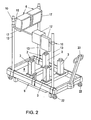
- Fig. 1 shows the perspective top view of a equipped with a test specimen, such as an internal combustion engine, pallet construction prepared for transport, for example, to a test bench not shown here
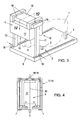
- Fig. 2 another embodiment of such a pallet construction without specimen
- Fig. 3 a further embodiment of a corresponding pallet construction with indicated test specimen
- Fig. 4 a partial section through a pallet construction, for example according to Fig. 1 or Fig. 3 in the region of the support arrangement for receiving and fastening various signal conditioning units - for example along the line IV - IV in Fig. 3 on an enlarged scale.
- test specimen 1 For the preparation and execution of test bench tests on a test piece 1, for example, an in Fig. 1 and Fig. 3 schematically drawn internal combustion engine, the test specimen 1 according to Fig. 1 to 3 mounted on a holding device 2, which usually has spatially adjustable holding elements 3, which allow an adaptation of the actual breakpoints to different specimens 1.
- sensors 4 On the holding device 2, this with sensors 4 (only in Fig. 1 indicated) in accordance with the experiments to be carried out, which in turn are connected via signal lines 5 with signal conditioning units 6 and from there via a common signal connection 7 with an evaluation device not shown on the test bed.
- the entire pallet construction 8, which has a preferably self-propelled base part 9, the retaining elements 3 of the holding device 2 arranged thereon, and a support arrangement 10 for receiving and fastening the signal conditioning units 6, thus becomes anticipated and remote from the test stand in a setup area with the test object 1, the sensors 4, the signal conditioning units 6 and the signal lines 5 and then transported in the fully assembled state to the test bench, where only the signal connection 7 (for example, a simple bus line) between the signal conditioning units 6 on the pallet construction 8 and the evaluation device not shown here will be installed.
- the specimen 1 is also in the test room of the test stand then, for example, with an electric drive or a power brake od. Like. To connect - a wave protection tunnel is in Fig. 1 marked and designated 11.
- Fig. 2 hinted way On the support assembly 10 may, for example in Fig. 2 hinted way, other measuring, display or control elements 12 may be attached, which may also be separated from the signal conditioning units 6.
- the assembled pallet construction 8, the od in the region of the base part 9 also not shown here functional elements, such as heat exchangers, media connections.
- functional elements such as heat exchangers, media connections.
- the test object can also be pretreated, for example, to operating temperature, on this occasion or else separately prior to the installation of the assembled pallet construction 8 in a conditioning area.
- the support assembly 10 has in all embodiments shown here at least two lateral posts 13, which according to Fig. 1 a telescopically, for example by means of hand winch, or electrically, pneumatically or hydraulically, extendable upper part 14, whereby the signal conditioning units 6 on the test bed in the conduct of the tests of the DUT 1 can be further removed, for example, to minimize temperature or vibration loads.
- the two lateral uprights 13 (or 14) are connected to a cross member 15, which decoupled via elastic elements 16 carries a receiving box 17 for the signal conditioning units 6.
- the signal conditioning units 6 - or else only some of them - could also be mounted separately in a vibration-proof manner in a rigid support arrangement.
- Fig. 1 and 4 are provided at the top of the receiving box 17 provided cooling or scavenging air openings 18, 19.
- the supplied through the openings 18 cooling air is conditioned, specially filtered or cooled separately, and flows through the interior of the double-walled support assembly 10 and receiving box 17 along the arrow 20 (FIGS. Fig. 4 ), whereby the arranged in the interior 21
- Signal conditioning units 6 can be cooled as needed.
- ambient air can be performed as purging air through the outer part of the double-walled receiving box 17, whereby heat input from the outside, for example, from the DUT 1, is suppressed.
- the openings 18 and 19 corresponding openings are in Fig. 3 each provided on one of the two uprights 13 in the region of their connection to the base part 9, in which case the two uprights 13 and the cross member 15 are connected via their hollow interiors - the separate supply of cooling air and scavenging air to the receiving box 17 is in Fig. 3 not shown separately.
- the support assembly 10 or receiving box 17 may be wholly or partially provided with an EMC shield, which is particularly advantageous if the individual signal conditioning units 6 to be accommodated therein do not themselves have such a shield.
- Fig. 1 and 2 refer to the underside of the base part 9 provided transport rollers 22 with which the pallet construction 8 itself is mobile.
- an operating device 23 is provided with the entire pallet construction 8 can be raised to the process and lowered in place.
- the pallet construction 8 according to Fig. 3 In contrast, is not self-mobile and can be transported, for example by means of a forklift.
- the arrangements after Fig. 1 to 3 can also be driven, for example, on docking ramps in the test room of the test bench and kept there stable, which in all cases also directly at least a portion of the required medium connections can be docked.
Landscapes
- Physics & Mathematics (AREA)
- General Physics & Mathematics (AREA)
- Testing Of Engines (AREA)
- Testing Of Devices, Machine Parts, Or Other Structures Thereof (AREA)
Claims (9)
- Procédé de préparation et d'exécution d'essais au banc sur une éprouvette (1), en particulier sur un ou plusieurs éléments qui coopèrent dans un véhicule automobile, par exemple dans une machine à combustion interne ou dans des parties d'une chaîne cinématique, l'éprouvette (1) étant montée sur une construction transportable en forme de palette (8) qui comprend une partie de base (9) de préférence automobile et des éléments de maintien (3) disposés sur celle-ci, pouvant de préférence être déplacés dans l'espace pour recevoir des éprouvettes (1) différentes, et le montage s'effectuant en dehors du banc d'essai dans une zone d'installation, caractérisé en ce que les capteurs (4) sont installés auparavant ou encore également dans la zone d'installation et en ce que des unités de conditionnement du signal (6) correspondantes sont disposées sur un agencement porteur (10, 17) de la construction en forme de palette (8) qui possède des canaux de circulation pour un fluide de refroidissement et sont raccordées aux capteurs (4), en ce que la construction en forme de palette (8) ainsi équipée est ensuite amenée sur le banc d'essai et installée par l'établissement d'une liaison de signaux (7) entre les unités de conditionnement du signal (6) sur la construction en forme de palette et l'équipement d'analyse du banc d'essai, les unités de conditionnement du signal (6) étant si besoin est refroidies à l'aide des canaux de circulation.
- Procédé selon la revendication 1, caractérisé en ce que la construction en forme de palette (8) équipée, avant son installation sur le banc d'essai, fait encore l'objet d'un essai fonctionnel dans la zone d'installation ou dans une zone d'essai située sur le trajet de transport avant le banc d'essai.
- Procédé selon l'une des revendications 1 ou 2, caractérisé en ce que l'éprouvette (1), avant l'installation de la construction en forme de palette (8) équipée sur le banc d'essai, fait l'objet d'un prétraitement dans une zone de conditionnement, par exemple est amenée à la température de fonctionnement.
- Construction en forme de palette destinée à être utilisée dans un procédé selon l'une des revendications 1 à 3, qui comprend une partie de base (9) de préférence automobile et des éléments de maintien (3) disposés sur celle-ci, pouvant de préférence être déplacés dans l'espace pour recevoir des éprouvettes (1) différentes, ainsi qu'un agencement porteur (10), caractérisé en ce que l'agencement porteur comprend des unités de conditionnement du signal (6) et en ce que les unités de conditionnement du signal (6) sont aptes à être refroidies à l'aide de canaux de circulation d'un fluide de refroidissement disposés dans l'agencement porteur (10, 17).
- Construction en forme de palette selon la revendication 4, caractérisée en ce que l'agencement porteur (10) est apte à être déplacé par rapport à la partie de base (9) et/ou est suspendu de manière à réaliser une isolation des vibrations par rapport à ce dernier.
- Construction en forme de palette selon l'une des revendications 4 ou 5, caractérisée en ce que les unités de conditionnement du signal (6) sont montées avec isolation des vibrations dans l'agencement porteur (10).
- Construction en forme de palette selon la revendication 6, caractérisée en ce que l'agencement porteur (10, 17) pour les unités de conditionnement du signal (6) est réalisé au moins partiellement à double paroi, un espace vide ainsi formé, adjacent aux unités de conditionnement du signal (6) sur au moins un côté, étant relié à une conduite d'amenée et d'évacuation de fluide de refroidissement, de préférence pour l'air ambiant.
- Construction en forme de palette selon la revendication 7, caractérisée en ce que l'espace intérieur (21) de l'agencement porteur (10, 17) à double paroi qui reçoit les unités de conditionnement du signal (6) est refroidi séparément à l'aide d'air de refroidissement filtré passant par des conduites d'amenée et d'évacuation.
- Construction en forme de palette selon l'une ou plusieurs des revendications 4 à 8, caractérisée en ce que l'agencement porteur (10, 17) possède un blindage CEM pour les unités de conditionnement du signal (6).
Applications Claiming Priority (2)
| Application Number | Priority Date | Filing Date | Title |
|---|---|---|---|
| AT3832003U | 2003-06-02 | ||
| AT0038303U AT6393U3 (de) | 2003-06-02 | 2003-06-02 | Verfahren zur vorbereitung und durchführung von prüfstandsversuchen sowie palettenkonstruktion zur verwendung in einem derartigen verfahren |
Publications (2)
| Publication Number | Publication Date |
|---|---|
| EP1484591A1 EP1484591A1 (fr) | 2004-12-08 |
| EP1484591B1 true EP1484591B1 (fr) | 2011-09-21 |
Family
ID=27625579
Family Applications (1)
| Application Number | Title | Priority Date | Filing Date |
|---|---|---|---|
| EP04450099A Expired - Lifetime EP1484591B1 (fr) | 2003-06-02 | 2004-04-28 | Procédé de préparation et de réalisation de tests sur banc d'essai et charriot-pallette associé |
Country Status (2)
| Country | Link |
|---|---|
| EP (1) | EP1484591B1 (fr) |
| AT (2) | AT6393U3 (fr) |
Families Citing this family (8)
| Publication number | Priority date | Publication date | Assignee | Title |
|---|---|---|---|---|
| AT501579B1 (de) * | 2004-12-01 | 2007-03-15 | Avl List Gmbh | Prüfstandsanordnung für fahrzeuge |
| AT10495U3 (de) | 2008-12-15 | 2009-10-15 | Avl List Gmbh | Verfahren und steuergerätepalette zum vorrüsten eines steuergeräteverbundes |
| AT11170U3 (de) * | 2009-12-23 | 2010-11-15 | Avl List Gmbh | Palettenkonstruktion, prüfstand zur aufnahme der palettenkonstruktion und verfahren zur vorbereitung von prüfstandsversuchen mit einer solchen palettenkonstruktion |
| AT11836U3 (de) * | 2011-01-13 | 2012-02-15 | Avl List Gmbh | Palettensystem mit einer rüstpalette und einer rüstpalettenaufnahme |
| DE102012212886B4 (de) * | 2012-07-23 | 2017-08-03 | Bayerische Motoren Werke Aktiengesellschaft | Mobiler Prüfstandaufbau auf einer fahrbaren Palettenkonstruktion zur Durchführung einer EMV-Messung |
| FR3039517B1 (fr) * | 2015-07-31 | 2019-05-17 | Safran Nacelles | Structure d’attenuation acoustique a multiples degres d’attenuation pour ensemble propulsif d’aeronef |
| AT518652B1 (de) * | 2016-12-30 | 2017-12-15 | Avl List Gmbh | Stützvorrichtung |
| CN110207989B (zh) * | 2019-05-29 | 2021-12-14 | 太原理工大学 | 一种发动机台架自动对中调节系统 |
Family Cites Families (5)
| Publication number | Priority date | Publication date | Assignee | Title |
|---|---|---|---|---|
| US4932628A (en) | 1988-03-03 | 1990-06-12 | Pacheco Orlando D | Portable engine test stand |
| US5629476A (en) | 1995-04-21 | 1997-05-13 | Sondey; Thomas F. | Modular fluid manifold system |
| US6253600B1 (en) | 1999-04-01 | 2001-07-03 | Thomas F. Sondey | Modular engine delivery apparatus |
| DE10049193B4 (de) * | 2000-10-05 | 2013-07-11 | Daimler Ag | Verfahren, dessen Verwendung und Vorrichtung zum mobilen Prüfen von Aggregaten, insbesondere von Kraftfahrzeug-Motoren und -Getrieben |
| DE10049192A1 (de) * | 2000-10-05 | 2002-04-11 | Daimler Chrysler Ag | Verfahren zum mobilen Prüfen von Aggregaten, insbesondere von Kraftfahrzeug-Motoren und -Getrieben |
-
2003
- 2003-06-02 AT AT0038303U patent/AT6393U3/de not_active IP Right Cessation
-
2004
- 2004-04-28 EP EP04450099A patent/EP1484591B1/fr not_active Expired - Lifetime
- 2004-04-28 AT AT04450099T patent/ATE525629T1/de active
Also Published As
| Publication number | Publication date |
|---|---|
| AT6393U3 (de) | 2004-04-26 |
| AT6393U2 (de) | 2003-09-25 |
| ATE525629T1 (de) | 2011-10-15 |
| EP1484591A1 (fr) | 2004-12-08 |
Similar Documents
| Publication | Publication Date | Title |
|---|---|---|
| DE102009051364B4 (de) | Schutzgehäuse für die Fahrzeugobjektprüfung | |
| DE69213031T2 (de) | LEITUNGSKANAL FüR GASTURBINENTRIEBWERKE | |
| EP2433761B1 (fr) | Dispositif doté d'une chambre climatisée contenant un robot | |
| DE112012003397B4 (de) | Hydraulikbagger | |
| EP1484591B1 (fr) | Procédé de préparation et de réalisation de tests sur banc d'essai et charriot-pallette associé | |
| DE3515010C2 (de) | Arbeitsverfahren und Prüfstand zur Untersuchung einer mit einer Brennkraftmaschine zusammenwirkenden Kfz-Einrichtung | |
| DE102013219471A1 (de) | Kraftfahrzeugprüfsystem | |
| DE102005027986B4 (de) | Verfahren und Anlage zum Zusammenbauen von Bauteilen einer Fahrzeugkarosserie | |
| DE3603709C2 (fr) | ||
| DE2515784A1 (de) | Anordnung einer klimaanlage in einem fahrzeug | |
| DE102009020182A1 (de) | Mobiler Prüfstand | |
| DE202009015830U1 (de) | Modulares verfahrbares Meßportal | |
| AT407922B (de) | Vorrichtung zum zuführen eines verbrennungsmotors zu einem motorprüfplatz, paletteneinheit und verfahren zur anbringung eines zu testenden verbrennungsmotors an einem motorprüfplatz | |
| DE19629454A1 (de) | Transportraupe | |
| EP4555294A1 (fr) | Banc d'essai pour tester les propriétés d'un module d'essieu à entraînement électrique pour un véhicule automobile | |
| DE10214495B4 (de) | Lastkraftwagen mit einer Anzahl von in einer kompakten Baugruppe hinter dem Fahrerhaus zusammengefassten Fahrzeugteilen | |
| AT501579B1 (de) | Prüfstandsanordnung für fahrzeuge | |
| DE19532855A1 (de) | Schienentriebfahrzeug | |
| DE10162787B4 (de) | Verfahren zur Leistungsermittlung und Leistungsprüfstand für einen Prüfling | |
| DE10360143B4 (de) | Verfahren zum Prüfen der Dichtheit eines Aggregats und Prüfsystem zur Durchführung des Verfahrens | |
| DE19634503B4 (de) | Straßenfertiger | |
| EP3220110B1 (fr) | Dispositif de pesage avec armoire de distribution | |
| DE102014116100A1 (de) | Mobiles Messgerät | |
| EP2934776B1 (fr) | Banc d'essai de véhicules automobiles | |
| DE3135679A1 (de) | Leistungspruefstand zur pruefung von verbrennungsmotoren |
Legal Events
| Date | Code | Title | Description |
|---|---|---|---|
| PUAI | Public reference made under article 153(3) epc to a published international application that has entered the european phase |
Free format text: ORIGINAL CODE: 0009012 |
|
| AK | Designated contracting states |
Kind code of ref document: A1 Designated state(s): AT BE BG CH CY CZ DE DK EE ES FI FR GB GR HU IE IT LI LU MC NL PL PT RO SE SI SK TR |
|
| AX | Request for extension of the european patent |
Extension state: AL HR LT LV MK |
|
| 17P | Request for examination filed |
Effective date: 20050518 |
|
| AKX | Designation fees paid |
Designated state(s): AT BE BG CH CY CZ DE DK EE ES FI FR GB GR HU IE IT LI LU MC NL PL PT RO SE SI SK TR |
|
| 17Q | First examination report despatched |
Effective date: 20070326 |
|
| GRAP | Despatch of communication of intention to grant a patent |
Free format text: ORIGINAL CODE: EPIDOSNIGR1 |
|
| GRAS | Grant fee paid |
Free format text: ORIGINAL CODE: EPIDOSNIGR3 |
|
| GRAA | (expected) grant |
Free format text: ORIGINAL CODE: 0009210 |
|
| AK | Designated contracting states |
Kind code of ref document: B1 Designated state(s): AT BE BG CH CY CZ DE DK EE ES FI FR GB GR HU IE IT LI LU MC NL PL PT RO SE SI SK TR |
|
| REG | Reference to a national code |
Ref country code: GB Ref legal event code: FG4D Free format text: NOT ENGLISH |
|
| REG | Reference to a national code |
Ref country code: CH Ref legal event code: EP |
|
| REG | Reference to a national code |
Ref country code: IE Ref legal event code: FG4D Free format text: LANGUAGE OF EP DOCUMENT: GERMAN |
|
| REG | Reference to a national code |
Ref country code: DE Ref legal event code: R096 Ref document number: 502004012879 Country of ref document: DE Effective date: 20111117 |
|
| REG | Reference to a national code |
Ref country code: NL Ref legal event code: VDEP Effective date: 20110921 |
|
| PG25 | Lapsed in a contracting state [announced via postgrant information from national office to epo] |
Ref country code: SE Free format text: LAPSE BECAUSE OF FAILURE TO SUBMIT A TRANSLATION OF THE DESCRIPTION OR TO PAY THE FEE WITHIN THE PRESCRIBED TIME-LIMIT Effective date: 20110921 Ref country code: FI Free format text: LAPSE BECAUSE OF FAILURE TO SUBMIT A TRANSLATION OF THE DESCRIPTION OR TO PAY THE FEE WITHIN THE PRESCRIBED TIME-LIMIT Effective date: 20110921 |
|
| PG25 | Lapsed in a contracting state [announced via postgrant information from national office to epo] |
Ref country code: CY Free format text: LAPSE BECAUSE OF FAILURE TO SUBMIT A TRANSLATION OF THE DESCRIPTION OR TO PAY THE FEE WITHIN THE PRESCRIBED TIME-LIMIT Effective date: 20110921 Ref country code: GR Free format text: LAPSE BECAUSE OF FAILURE TO SUBMIT A TRANSLATION OF THE DESCRIPTION OR TO PAY THE FEE WITHIN THE PRESCRIBED TIME-LIMIT Effective date: 20111222 Ref country code: SI Free format text: LAPSE BECAUSE OF FAILURE TO SUBMIT A TRANSLATION OF THE DESCRIPTION OR TO PAY THE FEE WITHIN THE PRESCRIBED TIME-LIMIT Effective date: 20110921 |
|
| REG | Reference to a national code |
Ref country code: IE Ref legal event code: FD4D |
|
| PG25 | Lapsed in a contracting state [announced via postgrant information from national office to epo] |
Ref country code: CZ Free format text: LAPSE BECAUSE OF FAILURE TO SUBMIT A TRANSLATION OF THE DESCRIPTION OR TO PAY THE FEE WITHIN THE PRESCRIBED TIME-LIMIT Effective date: 20110921 Ref country code: IE Free format text: LAPSE BECAUSE OF FAILURE TO SUBMIT A TRANSLATION OF THE DESCRIPTION OR TO PAY THE FEE WITHIN THE PRESCRIBED TIME-LIMIT Effective date: 20110921 Ref country code: SK Free format text: LAPSE BECAUSE OF FAILURE TO SUBMIT A TRANSLATION OF THE DESCRIPTION OR TO PAY THE FEE WITHIN THE PRESCRIBED TIME-LIMIT Effective date: 20110921 |
|
| PG25 | Lapsed in a contracting state [announced via postgrant information from national office to epo] |
Ref country code: NL Free format text: LAPSE BECAUSE OF FAILURE TO SUBMIT A TRANSLATION OF THE DESCRIPTION OR TO PAY THE FEE WITHIN THE PRESCRIBED TIME-LIMIT Effective date: 20110921 Ref country code: PL Free format text: LAPSE BECAUSE OF FAILURE TO SUBMIT A TRANSLATION OF THE DESCRIPTION OR TO PAY THE FEE WITHIN THE PRESCRIBED TIME-LIMIT Effective date: 20110921 Ref country code: PT Free format text: LAPSE BECAUSE OF FAILURE TO SUBMIT A TRANSLATION OF THE DESCRIPTION OR TO PAY THE FEE WITHIN THE PRESCRIBED TIME-LIMIT Effective date: 20120123 Ref country code: RO Free format text: LAPSE BECAUSE OF FAILURE TO SUBMIT A TRANSLATION OF THE DESCRIPTION OR TO PAY THE FEE WITHIN THE PRESCRIBED TIME-LIMIT Effective date: 20110921 Ref country code: EE Free format text: LAPSE BECAUSE OF FAILURE TO SUBMIT A TRANSLATION OF THE DESCRIPTION OR TO PAY THE FEE WITHIN THE PRESCRIBED TIME-LIMIT Effective date: 20110921 |
|
| PLBI | Opposition filed |
Free format text: ORIGINAL CODE: 0009260 |
|
| PLAX | Notice of opposition and request to file observation + time limit sent |
Free format text: ORIGINAL CODE: EPIDOSNOBS2 |
|
| PG25 | Lapsed in a contracting state [announced via postgrant information from national office to epo] |
Ref country code: DK Free format text: LAPSE BECAUSE OF FAILURE TO SUBMIT A TRANSLATION OF THE DESCRIPTION OR TO PAY THE FEE WITHIN THE PRESCRIBED TIME-LIMIT Effective date: 20110921 |
|
| 26 | Opposition filed |
Opponent name: TECHNOGERMA SYSTEMS GMBH Effective date: 20120621 |
|
| REG | Reference to a national code |
Ref country code: DE Ref legal event code: R026 Ref document number: 502004012879 Country of ref document: DE Effective date: 20120621 |
|
| BERE | Be: lapsed |
Owner name: AVL LIST GMBH Effective date: 20120430 |
|
| PG25 | Lapsed in a contracting state [announced via postgrant information from national office to epo] |
Ref country code: MC Free format text: LAPSE BECAUSE OF NON-PAYMENT OF DUE FEES Effective date: 20120430 |
|
| REG | Reference to a national code |
Ref country code: CH Ref legal event code: PL |
|
| PLBB | Reply of patent proprietor to notice(s) of opposition received |
Free format text: ORIGINAL CODE: EPIDOSNOBS3 |
|
| PG25 | Lapsed in a contracting state [announced via postgrant information from national office to epo] |
Ref country code: BE Free format text: LAPSE BECAUSE OF NON-PAYMENT OF DUE FEES Effective date: 20120430 Ref country code: LI Free format text: LAPSE BECAUSE OF NON-PAYMENT OF DUE FEES Effective date: 20120430 Ref country code: CH Free format text: LAPSE BECAUSE OF NON-PAYMENT OF DUE FEES Effective date: 20120430 |
|
| REG | Reference to a national code |
Ref country code: CH Ref legal event code: PK Free format text: DAS PRIORITAETSAKTENZEICHEN WURDE BERICHTIGT: AT 38303 U / 02.06.2003 |
|
| PG25 | Lapsed in a contracting state [announced via postgrant information from national office to epo] |
Ref country code: ES Free format text: LAPSE BECAUSE OF FAILURE TO SUBMIT A TRANSLATION OF THE DESCRIPTION OR TO PAY THE FEE WITHIN THE PRESCRIBED TIME-LIMIT Effective date: 20120101 |
|
| PG25 | Lapsed in a contracting state [announced via postgrant information from national office to epo] |
Ref country code: BG Free format text: LAPSE BECAUSE OF FAILURE TO SUBMIT A TRANSLATION OF THE DESCRIPTION OR TO PAY THE FEE WITHIN THE PRESCRIBED TIME-LIMIT Effective date: 20111221 |
|
| PLAB | Opposition data, opponent's data or that of the opponent's representative modified |
Free format text: ORIGINAL CODE: 0009299OPPO |
|
| R26 | Opposition filed (corrected) |
Opponent name: TECHNOGERMA SYSTEMS GMBH Effective date: 20120621 |
|
| PG25 | Lapsed in a contracting state [announced via postgrant information from national office to epo] |
Ref country code: TR Free format text: LAPSE BECAUSE OF FAILURE TO SUBMIT A TRANSLATION OF THE DESCRIPTION OR TO PAY THE FEE WITHIN THE PRESCRIBED TIME-LIMIT Effective date: 20110921 |
|
| PG25 | Lapsed in a contracting state [announced via postgrant information from national office to epo] |
Ref country code: LU Free format text: LAPSE BECAUSE OF NON-PAYMENT OF DUE FEES Effective date: 20120428 |
|
| PG25 | Lapsed in a contracting state [announced via postgrant information from national office to epo] |
Ref country code: HU Free format text: LAPSE BECAUSE OF FAILURE TO SUBMIT A TRANSLATION OF THE DESCRIPTION OR TO PAY THE FEE WITHIN THE PRESCRIBED TIME-LIMIT Effective date: 20040428 |
|
| PLBP | Opposition withdrawn |
Free format text: ORIGINAL CODE: 0009264 |
|
| PLBD | Termination of opposition procedure: decision despatched |
Free format text: ORIGINAL CODE: EPIDOSNOPC1 |
|
| PLBM | Termination of opposition procedure: date of legal effect published |
Free format text: ORIGINAL CODE: 0009276 |
|
| STAA | Information on the status of an ep patent application or granted ep patent |
Free format text: STATUS: OPPOSITION PROCEDURE CLOSED |
|
| 27C | Opposition proceedings terminated |
Effective date: 20150420 |
|
| REG | Reference to a national code |
Ref country code: FR Ref legal event code: PLFP Year of fee payment: 13 |
|
| REG | Reference to a national code |
Ref country code: FR Ref legal event code: PLFP Year of fee payment: 14 |
|
| REG | Reference to a national code |
Ref country code: FR Ref legal event code: PLFP Year of fee payment: 15 |
|
| PGFP | Annual fee paid to national office [announced via postgrant information from national office to epo] |
Ref country code: DE Payment date: 20180420 Year of fee payment: 15 |
|
| PGFP | Annual fee paid to national office [announced via postgrant information from national office to epo] |
Ref country code: AT Payment date: 20180424 Year of fee payment: 15 Ref country code: IT Payment date: 20180423 Year of fee payment: 15 Ref country code: FR Payment date: 20180420 Year of fee payment: 15 |
|
| PGFP | Annual fee paid to national office [announced via postgrant information from national office to epo] |
Ref country code: GB Payment date: 20180418 Year of fee payment: 15 |
|
| REG | Reference to a national code |
Ref country code: DE Ref legal event code: R119 Ref document number: 502004012879 Country of ref document: DE |
|
| REG | Reference to a national code |
Ref country code: AT Ref legal event code: MM01 Ref document number: 525629 Country of ref document: AT Kind code of ref document: T Effective date: 20190428 |
|
| GBPC | Gb: european patent ceased through non-payment of renewal fee |
Effective date: 20190428 |
|
| PG25 | Lapsed in a contracting state [announced via postgrant information from national office to epo] |
Ref country code: DE Free format text: LAPSE BECAUSE OF NON-PAYMENT OF DUE FEES Effective date: 20191101 Ref country code: GB Free format text: LAPSE BECAUSE OF NON-PAYMENT OF DUE FEES Effective date: 20190428 Ref country code: AT Free format text: LAPSE BECAUSE OF NON-PAYMENT OF DUE FEES Effective date: 20190428 |
|
| PG25 | Lapsed in a contracting state [announced via postgrant information from national office to epo] |
Ref country code: IT Free format text: LAPSE BECAUSE OF NON-PAYMENT OF DUE FEES Effective date: 20190428 |
|
| PG25 | Lapsed in a contracting state [announced via postgrant information from national office to epo] |
Ref country code: FR Free format text: LAPSE BECAUSE OF NON-PAYMENT OF DUE FEES Effective date: 20190430 |