EP1484112B1 - Support ajustable en hauteur, et méthode de découplage du système de maintien associé à ce support - Google Patents
Support ajustable en hauteur, et méthode de découplage du système de maintien associé à ce support Download PDFInfo
- Publication number
- EP1484112B1 EP1484112B1 EP04021676A EP04021676A EP1484112B1 EP 1484112 B1 EP1484112 B1 EP 1484112B1 EP 04021676 A EP04021676 A EP 04021676A EP 04021676 A EP04021676 A EP 04021676A EP 1484112 B1 EP1484112 B1 EP 1484112B1
- Authority
- EP
- European Patent Office
- Prior art keywords
- cable
- holding device
- stand
- end point
- drive motor
- Prior art date
- Legal status (The legal status is an assumption and is not a legal conclusion. Google has not performed a legal analysis and makes no representation as to the accuracy of the status listed.)
- Expired - Lifetime
Links
- 238000000034 method Methods 0.000 title claims description 5
- 238000004146 energy storage Methods 0.000 claims description 10
- 239000011521 glass Substances 0.000 claims 3
- 230000008878 coupling Effects 0.000 description 8
- 238000010168 coupling process Methods 0.000 description 8
- 238000005859 coupling reaction Methods 0.000 description 8
- 239000006066 glass batch Substances 0.000 description 5
- 238000010438 heat treatment Methods 0.000 description 5
- 229910000831 Steel Inorganic materials 0.000 description 2
- XAGFODPZIPBFFR-UHFFFAOYSA-N aluminium Chemical compound [Al] XAGFODPZIPBFFR-UHFFFAOYSA-N 0.000 description 2
- 229910052782 aluminium Inorganic materials 0.000 description 2
- 230000002040 relaxant effect Effects 0.000 description 2
- 239000010959 steel Substances 0.000 description 2
- 230000001419 dependent effect Effects 0.000 description 1
- 238000006073 displacement reaction Methods 0.000 description 1
- 230000000694 effects Effects 0.000 description 1
- 230000008020 evaporation Effects 0.000 description 1
- 238000001704 evaporation Methods 0.000 description 1
- 238000013021 overheating Methods 0.000 description 1
- XLYOFNOQVPJJNP-UHFFFAOYSA-N water Substances O XLYOFNOQVPJJNP-UHFFFAOYSA-N 0.000 description 1
- 238000004804 winding Methods 0.000 description 1
Images


Classifications
-
- B—PERFORMING OPERATIONS; TRANSPORTING
- B01—PHYSICAL OR CHEMICAL PROCESSES OR APPARATUS IN GENERAL
- B01L—CHEMICAL OR PHYSICAL LABORATORY APPARATUS FOR GENERAL USE
- B01L9/00—Supporting devices; Holding devices
- B01L9/04—Retort stands; Retort clamps
-
- B—PERFORMING OPERATIONS; TRANSPORTING
- B01—PHYSICAL OR CHEMICAL PROCESSES OR APPARATUS IN GENERAL
- B01D—SEPARATION
- B01D3/00—Distillation or related exchange processes in which liquids are contacted with gaseous media, e.g. stripping
- B01D3/08—Distillation or related exchange processes in which liquids are contacted with gaseous media, e.g. stripping in rotating vessels; Atomisation on rotating discs
- B01D3/085—Distillation or related exchange processes in which liquids are contacted with gaseous media, e.g. stripping in rotating vessels; Atomisation on rotating discs using a rotary evaporator
-
- F—MECHANICAL ENGINEERING; LIGHTING; HEATING; WEAPONS; BLASTING
- F16—ENGINEERING ELEMENTS AND UNITS; GENERAL MEASURES FOR PRODUCING AND MAINTAINING EFFECTIVE FUNCTIONING OF MACHINES OR INSTALLATIONS; THERMAL INSULATION IN GENERAL
- F16M—FRAMES, CASINGS OR BEDS OF ENGINES, MACHINES OR APPARATUS, NOT SPECIFIC TO ENGINES, MACHINES OR APPARATUS PROVIDED FOR ELSEWHERE; STANDS; SUPPORTS
- F16M11/00—Stands or trestles as supports for apparatus or articles placed thereon ; Stands for scientific apparatus such as gravitational force meters
- F16M11/02—Heads
- F16M11/04—Means for attachment of apparatus; Means allowing adjustment of the apparatus relatively to the stand
- F16M11/043—Allowing translations
- F16M11/046—Allowing translations adapted to upward-downward translation movement
-
- F—MECHANICAL ENGINEERING; LIGHTING; HEATING; WEAPONS; BLASTING
- F16—ENGINEERING ELEMENTS AND UNITS; GENERAL MEASURES FOR PRODUCING AND MAINTAINING EFFECTIVE FUNCTIONING OF MACHINES OR INSTALLATIONS; THERMAL INSULATION IN GENERAL
- F16M—FRAMES, CASINGS OR BEDS OF ENGINES, MACHINES OR APPARATUS, NOT SPECIFIC TO ENGINES, MACHINES OR APPARATUS PROVIDED FOR ELSEWHERE; STANDS; SUPPORTS
- F16M11/00—Stands or trestles as supports for apparatus or articles placed thereon ; Stands for scientific apparatus such as gravitational force meters
- F16M11/02—Heads
- F16M11/18—Heads with mechanism for moving the apparatus relatively to the stand
-
- F—MECHANICAL ENGINEERING; LIGHTING; HEATING; WEAPONS; BLASTING
- F16—ENGINEERING ELEMENTS AND UNITS; GENERAL MEASURES FOR PRODUCING AND MAINTAINING EFFECTIVE FUNCTIONING OF MACHINES OR INSTALLATIONS; THERMAL INSULATION IN GENERAL
- F16M—FRAMES, CASINGS OR BEDS OF ENGINES, MACHINES OR APPARATUS, NOT SPECIFIC TO ENGINES, MACHINES OR APPARATUS PROVIDED FOR ELSEWHERE; STANDS; SUPPORTS
- F16M2200/00—Details of stands or supports
- F16M2200/02—Locking means
- F16M2200/025—Locking means for translational movement
- F16M2200/027—Locking means for translational movement by friction
-
- F—MECHANICAL ENGINEERING; LIGHTING; HEATING; WEAPONS; BLASTING
- F16—ENGINEERING ELEMENTS AND UNITS; GENERAL MEASURES FOR PRODUCING AND MAINTAINING EFFECTIVE FUNCTIONING OF MACHINES OR INSTALLATIONS; THERMAL INSULATION IN GENERAL
- F16M—FRAMES, CASINGS OR BEDS OF ENGINES, MACHINES OR APPARATUS, NOT SPECIFIC TO ENGINES, MACHINES OR APPARATUS PROVIDED FOR ELSEWHERE; STANDS; SUPPORTS
- F16M2200/00—Details of stands or supports
- F16M2200/04—Balancing means
- F16M2200/048—Balancing means for balancing translational movement of the undercarriage
Definitions
- the invention relates to a height-adjustable tripod, in particular a tripod for rotary evaporator and a method for disengaging the holding device in a tripod with the features of the preamble of the independent claims.
- tripods also called quick lift devices, for example, an evaporator flask can be kept in a water bath. Since the evaporation process can be stopped only by quickly lifting the piston out of the heating bath, an effortless and rapid adjustment of the tripod is desired.
- Such height-adjustable tripods are made for example EP 149 972 . DE 26 49 950 . EP 05 38 186 or DE 27 58 433 known.
- a first requirement with such stands is the motor and at the same time the manual operation of the tripod.
- the holding device for the evaporator flask should also be able to be manually raised quickly and easily from the heating bath in an emergency even with a motor drive manually.
- the possibility of decoupling the holding device from the drive motor should be simplified.
- the holding device should be able to be decoupled quickly and with little effort from the drive motor.
- the inventive tripod should also be able to be produced in a simple and economical manner without great design effort.
- Another object of the invention is therefore to provide a tripod for a rotary evaporator, which can be lifted automatically or only by a few simple steps of the user from the heating bath at an interruption of the rotational movement of the evaporator flask.
- the height-adjustable tripod is particularly suitable for a rotary evaporator. But there would also be other purposes conceivable.
- the tripod has a holding device for attaching a glassware.
- the glass batch typically consists of a flask of a rotary evaporator.
- the holding device is provided with devices known per se for rotating the glassware.
- the content of EP 149 972 is, as regards the configuration of the glass batch and the holding device, explicitly included by cross-reference in the present application.
- the tripod also has a stand rod.
- the holding device is displaceable along the stand rod.
- the holding device may also be provided with a cooperating with a coupling element, e.g. to be able to be brought into operative connection with a cable winch wound around a cable drum.
- a drive motor is arranged on the holding device itself.
- the motor can be brought into engagement with holding means fixed relative to the stand rod.
- the cable can be fixed in such a way that the tension of the cable is changeable. In a first position, the tension of the cable is maximum and generates frictional engagement with the coupling element, in particular with the cable drum. In a second position, the tension is minimal and the frictional engagement between cable and cable drum is canceled.
- the holding device which is in operative connection with the cable drum, moves by turning the cable drum.
- the holding device In the second position, the holding device is decoupled from the cable drum due to the lack of frictional engagement between cable and cable drum.
- the holding device In the second position, the holding device can therefore simply be moved manually, for example, lifted up.
- the holding device In the first position, the holding device is not freely movable due to the frictional engagement between the cable and the cable drum.
- the holding device moves.
- the holding device stops, the holding device remains in a fixed position.
- frictional engagement is understood to mean an at least partially force-transmitting connection between the cable pull and the cable drum.
- a movement of the cable drum leads to a movement of the cable.
- the holding device with respect to the tripod is freely movable and can be lifted.
- the cable drum is preferably rotatably mounted and driven by a motor. But it is also conceivable to provide a non-rotatable cable drum on the holding device and to drive the cable in any other suitable manner.
- the drive motor may be provided with a gear which engages the rack and which can be brought out of engagement with the rack for decoupling the holding device.
- the holding means are designed as a cable, which is fixed relative to the stand rod.
- the drive motor is provided with a cable drum around which the cable is wound.
- the cable takes over the function of the rack in this case.
- the holding device can be decoupled from the cable by reducing the tension of the cable.
- the cable is preferably clamped between a fixed end point and a movable end point. By moving the one end point in the direction of the cable tension of the cable can be reduced.
- a rotation of the cable drum leads to a movement of the holding device carrying the cable drum.
- the holding device can move freely.
- the cable is self-contained and firmly connected to the holding device.
- the cable is wound around a rotatably mounted cable drum, which is fixedly arranged with respect to the stand rod.
- the cable is guided around two pulleys.
- the rope tension can be varied. If the cable tension is sufficiently high, the frictional connection between the cable drum and the cable is sufficiently large so that a rotation of the cable drum leads to a movement of the holding device. If the cable tension is sufficiently low, there is no frictional connection, so that the holding device can be moved freely.
- the cable can also be wound around a rope drum fixedly connected to the holding device and driven by suitable means.
- the movable end point of the clamped between the two end points cable is designed as a fixation, which is biased by a spring.
- the spring generates sufficient tension on the cable so that in normal condition the cable drum is in frictional connection with the cable.
- the tripod is also provided with an actuating arm for moving the fixation against the spring force.
- the actuating arm may be rotatably mounted about a pivot point, so that a leverage is generated. By operating the actuating arm, the tension of the cable is reduced and the cable is decoupled from the cable drum. The holding device can be moved freely when the actuating arm.
- a motor mobility of the movable end point allows automatic decoupling of the holding device during a stoppage of the rotary evaporator.
- an arrangement for automatically moving the movable end point can be provided at standstill of a rotatably held glass batch.
- a particularly preferred embodiment of the invention results when the holding device is also connected via a force storage device directly or indirectly with the stand rod.
- the holding device can be lowered against the force of the energy storage and lifted by means of the energy storage.
- the cable is tensioned
- the cable is in frictional connection with the cable drum.
- the holding device in a non-rotating cable drum remains in a certain position despite the energy storage.
- the holding device is moved against the force or with the assistance of the energy storage.
- the tension of the cable is reduced, the frictional engagement between the cable drum and the cable is released so that the holding device is automatically lifted with the aid of the energy accumulator.
- This arrangement is particularly advantageous in combination with the actuating arm described above. By simply pressing the actuating arm, the tension of the spring tension is reduced and the holding device is automatically lifted thanks to the energy storage.
- the tension necessary to achieve frictional engagement between the cable drum and the cable depends not only on the coefficients of friction of the cable drum and the cable, but also on the magnitude of the force of the force accumulator and the weight of the holder.
- the tension of the cable is dimensioned according to the possible weights of the holding device and according to the force of the force accumulator.
- the holding device can preferably be displaceably mounted on rollers along a stand rod.
- the stand rod is preferably formed as a profile having guide rails for the rollers.
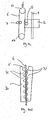
- FIG. 1 shows a height-adjustable stand 1.
- the stand 1 consists essentially of a base plate 21, on which a stand rod 4 is fixed.
- a holding device 2 is slidably mounted.
- the holding device 2 serves to receive a glassware, in particular a piston for a rotary evaporator.
- the holding device is also provided with an arrangement for rotating the glass batch.
- the tripod is assigned a heating bath. The design of the heating bath and the turning device for the glass batch is known in the art and will not be explained in detail.
- the holding device 2 is also provided with a drive motor 7.
- the drive motor 7 drives a cable drum 5 via a gear arrangement, not shown.
- the stand rod 4 is provided with a cable 6.
- the cable 6 is attached to one end 8 with a fixed end point on the tripod.
- the other end 9 of the cable 6 is held in a movable fixation.
- the movable fixing consists of an actuating arm 12.
- the actuating arm 12 is provided with a bore 25 through which the cable 6 is guided.
- the cable 6 is held on the surface of the actuating arm 12 with a screw 11.
- the actuating arm 12 and Thus, the movable end point 9 of the cable 6 are in a direction R along the cable against the force of a spring 10 slidably.
- the actuating arm 12 is rotatably mounted about a pivot point 19. By pushing down the end 18 of the actuating arm 12 in the arrow direction, the movable end 9 of the cable 6 is pivoted upwards in the direction of the arrow. The position of the screw 11 'and the actuating arm 12' in against the spring tensioned position is shown in dashed lines.
- the cable 6 is wound around the cable drum 5.
- a winding is provided at 720 °. But to change the friction effect, it may also be possible to provide more or fewer wraps.
- the holding device 2 is also connected via a force accumulator 14 with the stand rod 4 and connected to the stand rod 4 elements.
- the energy storage 14 is shown schematically as a spring. There are next spiral springs and gas spring or other power storage conceivable.
- the holding device 4 can be suspended from a force storage device 14 under tension or be supported on a compressible energy store. Gas springs are particularly preferred in this context.
- the actuating arm 12 is due to the force of the spring 10 in the position shown by solid lines.
- the cable 6 is stretched and is connected to the cable drum 5 in ReiMED.
- the force of the spring 10 is chosen sufficiently large, so that the frictional force between the cable drum 5 and cable 6 is sufficient to the force of the Force accumulator 14 and the weight of the holding device 2 (and a mounted glassware) to compensate. If the cable drum 5 does not rotate, the holding device 2 remains in a certain position. By stopping the cable drum 5, the holding device 2 is detected. Once the cable drum 5 is rotated in tensioned cable 6, the holding device 2 is lifted according to the direction of rotation of the cable drum 5 or moved down.
- the cable 6 is preferably made of a sheathed steel cable or a plastic rope, such as Keflar.
- the cable drum 5 is made of steel or aluminum.
- the holding device is constructed as a carriage mounted so as to be displaceable along the stand rod.
- the car can be made of aluminum or plastic.
- the drive motor 7 shown schematically is preferably designed as an electric motor.
- FIG. 2 shows a plan view of the stand rod 4 and the holding device 2.
- the stand rod 4 is formed as a guide rail having guides 20.
- the holding device 2 has three rollers 15, which slide in the guide rails 20.
- the three rollers 15 are arranged in one plane. In one of the guide rails 20, a roller slides while two rollers slide in the other guide rail 20. Due to the three-point support, a particularly stable and tilt-free guidance of the holding device 2 along the support rod 4 is achieved.
- the drive motor 7 is fixedly connected to the holding device 2 and drives the cable drum 5 fixedly connected to the holding device.
- the cable drum 5 is shown enlarged in side view.
- the cable 6 is wound around the cable drum 5 through an angle of 1080 ° (i.e., 3 times).
- FIG. 4b shows an alternative embodiment of the invention.
- the holding device 2 is veschiebbar along the stand rod 4 and fixed to a cable 6.
- the cable 6 is self-contained and is deflected by two pulleys 17.
- the stand also has a cable drum 5 with a drive motor 7.
- the cable drum 5 is fixedly arranged with respect to the stand rod 4.
- the cable 6 is wound around the cable drum 5.
- One of the two pulleys 17 is also movable designed so that the tension on the cable 6 can be changed. In a tensioned cable 6, the frictional force between the cable 6 and the cable drum 5 is sufficiently large, so that rotation of the cable drum 5 leads to a movement of the holding device 2 or thus fixed at the cable drum 5, the holding device 2 is detected.
- the cable 6 is decoupled from the cable drum 5 and the holding device 2 can be moved freely.
- the details shown in FIG. 1, in particular force accumulator, actuating arm are likewise advantageous.
- the actuating arm can be used to move the movable, for example, the upper guide roller 17 in a similar manner.
- FIG. 4b shows an alternative embodiment of the invention.
- the drive motor 9 is firmly connected to the holding device 2.
- the drive motor 9 has a gear 22, which is engageable with a rack 16 in engagement.
- the rack 16 is fixedly connected to the stand rod 4.
- the gear 22 can be brought out of engagement with the rack 16.
- the holding device 2 can thus also move freely.
- the holding device 2 has a non-rotatable, acting as a coupling element cable drum 5, around which the cable 6 is wound.
- the cable 6 can be driven by a motor 7, which rotates the cable 6 trapping rollers. By relaxing the cable 6, the frictional engagement between the cable drum 5 and the cable 6 is released.
- the holding device is freely movable.
- FIG. 4d shows an alternative coupling system 30.
- the coupling system can be used instead of the cable drum 5 in the embodiment according to Figure 4c.
- tensioned cable 6 is frictional engagement between the inwardly directed lugs 31 of the coupling element 30 and the cable 6.
- relaxed cable 6 shown in phantom
- the cable 6 slides in the coupling element 30th
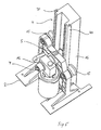
- Figure 5 shows a perspective view of a section of the holding device 2, which is held displaceably along the stand rod 4.
- the stand rod 4 is designed as a guide rail, which has two guides 20.
- the holding device 2 is slidably mounted in the guide rails 20 with three rollers 15.
- a first roll runs in a first Guide rail 20 (see right side in Figure 5).
- two rollers 15 are mounted, wherein the lower roller 15 is covered by the drive motor 9 and a gear assembly.
- the cable drum 5 is mounted on a driven by the drive motor 7 shaft.
Landscapes
- Engineering & Computer Science (AREA)
- General Engineering & Computer Science (AREA)
- Mechanical Engineering (AREA)
- Chemical & Material Sciences (AREA)
- Chemical Kinetics & Catalysis (AREA)
- Health & Medical Sciences (AREA)
- Clinical Laboratory Science (AREA)
- Storing, Repeated Paying-Out, And Re-Storing Of Elongated Articles (AREA)
- Devices For Use In Laboratory Experiments (AREA)
- Unwinding Of Filamentary Materials (AREA)
- Window Of Vehicle (AREA)
Claims (12)
- Support comprenant un dispositif de maintien (2) pour la fixation d'un ensemble de récipients en verre, lequel dispositif de maintien (2) peut être déplacé le long d'une barre du support (4) et présente un moteur d'entraînement (7) au moyen duquel le dispositif de maintien (2) peut être entraîné,
caractérisé en ce que le moteur d'entraînement (7) est disposé sur le dispositif de maintien (2) et peut être amené en prise avec des moyens de maintien fixes par rapport à la barre du support (4) et en être désaccouplé. - Support selon la revendication 1, caractérisé en ce qu'un câble (6) est tendu entre un point terminal (8) fixe par rapport au support et un point terminal (9) mobile, le point terminal mobile (9) pouvant être déplacé dans la direction (R) du câble (6).
- Support selon la revendication 2, caractérisé en ce que le point terminal mobile (9) est réalisé sous la forme d'une fixation précontrainte par un ressort (10) pour le câble (6).
- Support selon l'une quelconque des revendications 2 ou 3, caractérisé en ce que le support est pourvu d'un bras d'actionnement (12) pour déplacer le point terminal mobile (9) à l'encontre de la force du ressort (10).
- Support selon l'une quelconque des revendications 2 à 4, caractérisé en ce que le point terminal mobile (9) peut être déplacé par un moteur.
- Support selon la revendication 5, caractérisé en ce que le support présente un agencement pour le déplacement automatique du point terminal mobile (9), notamment si un ensemble de récipients en verre maintenu de manière rotative est immobile, de sorte que le câble (6) puisse être détendu.
- Support selon l'une quelconque des revendications 1 à 6, caractérisé en ce que le dispositif de maintien (2) est connecté directement ou indirectement à la barre du support (4) au moyen d'un accumulateur de force (14), le dispositif de maintien (2) pouvant être abaissé à l'encontre de la force de l'accumulateur de force (14) et pouvant être soulevé à l'aide de l'accumulateur de force (14).
- Support selon l'une quelconque des revendications 1 à 7, caractérisé en ce que le dispositif de maintien (2) est monté avec des galets (15), de préférence avec trois galets (15), de manière déplaçable sur la barre du support.
- Support selon la revendication 8, caractérisé en ce que la barre du support (4) est réalisée sous la forme d'un rail de guidage avec des coulisses (20) le long desquelles les galets (15) sont guidés.
- Support selon l'une quelconque des revendications 1 à 9, caractérisé en ce que le tambour du câble (5) est monté à rotation et peut de préférence être entraîné par un moteur.
- Procédé pour désaccoupler le dispositif de maintien (2) pour un ensemble de récipients en verre sur le support d'un évaporateur rotatif d'un moteur d'entraînement (7), le moteur d'entraînement (7) étant monté sur le dispositif de maintien, caractérisé en ce que le moteur d'entraînement est désaccouplé pour le désaccouplement de moyens de maintien fixes par rapport à la barre du support.
- Evaporateur rotatif comprenant un support selon l'une quelconque des revendications 1 à 10.
Applications Claiming Priority (1)
| Application Number | Priority Date | Filing Date | Title |
|---|---|---|---|
| EP19990113391 EP1068903B1 (fr) | 1999-07-10 | 1999-07-10 | Support ajustable en hauteur, et méthode de découplage du système de maintien associé à ce support |
Related Parent Applications (1)
| Application Number | Title | Priority Date | Filing Date |
|---|---|---|---|
| EP19990113391 Division EP1068903B1 (fr) | 1999-07-10 | 1999-07-10 | Support ajustable en hauteur, et méthode de découplage du système de maintien associé à ce support |
Publications (3)
| Publication Number | Publication Date |
|---|---|
| EP1484112A2 EP1484112A2 (fr) | 2004-12-08 |
| EP1484112A3 EP1484112A3 (fr) | 2005-01-12 |
| EP1484112B1 true EP1484112B1 (fr) | 2007-09-05 |
Family
ID=8238563
Family Applications (2)
| Application Number | Title | Priority Date | Filing Date |
|---|---|---|---|
| EP04021676A Expired - Lifetime EP1484112B1 (fr) | 1999-07-10 | 1999-07-10 | Support ajustable en hauteur, et méthode de découplage du système de maintien associé à ce support |
| EP19990113391 Expired - Lifetime EP1068903B1 (fr) | 1999-07-10 | 1999-07-10 | Support ajustable en hauteur, et méthode de découplage du système de maintien associé à ce support |
Family Applications After (1)
| Application Number | Title | Priority Date | Filing Date |
|---|---|---|---|
| EP19990113391 Expired - Lifetime EP1068903B1 (fr) | 1999-07-10 | 1999-07-10 | Support ajustable en hauteur, et méthode de découplage du système de maintien associé à ce support |
Country Status (3)
| Country | Link |
|---|---|
| EP (2) | EP1484112B1 (fr) |
| JP (1) | JP2001054740A (fr) |
| DE (2) | DE59910522D1 (fr) |
Families Citing this family (6)
| Publication number | Priority date | Publication date | Assignee | Title |
|---|---|---|---|---|
| DE102011115420B4 (de) * | 2011-10-08 | 2015-03-12 | Knf Neuberger Gmbh | Rotationsverdampfer |
| DE202011106534U1 (de) | 2011-10-08 | 2013-01-09 | Knf Neuberger Gmbh | Rotationsverdampfer |
| NL2011863C2 (en) * | 2013-11-29 | 2015-06-01 | Linear Adjustment Dev Ltd | Driving device for a support column. |
| CN106378219A (zh) * | 2016-11-22 | 2017-02-08 | 遵义医学院 | 一种点滴管存放托架 |
| CN107255216A (zh) * | 2017-06-20 | 2017-10-17 | 姜素娥 | 一种电力专用抄表架 |
| KR102041975B1 (ko) * | 2019-03-14 | 2019-11-07 | (주)미동엔지니어링 | 배전선로의 처짐 방지 장치 |
Family Cites Families (5)
| Publication number | Priority date | Publication date | Assignee | Title |
|---|---|---|---|---|
| DE3330764C2 (de) * | 1982-10-15 | 1994-10-27 | Yamato Scient Co Ltd | Rotationsverdampfer |
| EP0149972B1 (fr) * | 1983-12-09 | 1987-08-05 | Büchi Laboratoriums-Technik AG | Support ajustable en hauteur pour évaporateur rotatif |
| DE59206846D1 (de) * | 1991-10-18 | 1996-09-05 | Buechi Lab Tech | Höhenverstellbares Stativ für Laborgeräte |
| DE9115778U1 (fr) * | 1991-12-19 | 1992-02-13 | Buechi Laboratoriums-Technik Ag, Flawil, Ch | |
| DE4200118A1 (de) * | 1992-01-04 | 1993-07-08 | G & W Buehler Maschinenbau Gmb | Handhabungsgeraet |
-
1999
- 1999-07-10 EP EP04021676A patent/EP1484112B1/fr not_active Expired - Lifetime
- 1999-07-10 DE DE59910522T patent/DE59910522D1/de not_active Expired - Lifetime
- 1999-07-10 EP EP19990113391 patent/EP1068903B1/fr not_active Expired - Lifetime
- 1999-07-10 DE DE59914491T patent/DE59914491D1/de not_active Expired - Lifetime
-
2000
- 2000-07-10 JP JP2000208266A patent/JP2001054740A/ja active Pending
Also Published As
| Publication number | Publication date |
|---|---|
| EP1068903B1 (fr) | 2004-09-15 |
| EP1484112A2 (fr) | 2004-12-08 |
| JP2001054740A (ja) | 2001-02-27 |
| EP1484112A3 (fr) | 2005-01-12 |
| DE59914491D1 (de) | 2007-10-18 |
| DE59910522D1 (de) | 2004-10-21 |
| EP1068903A1 (fr) | 2001-01-17 |
Similar Documents
| Publication | Publication Date | Title |
|---|---|---|
| EP1207334B1 (fr) | Support | |
| DE102007053588A1 (de) | Abrollvorrichtung für Wickelrollen | |
| WO2006042354A1 (fr) | Pince a souder par points et procede pour regler la pression d'une pince a souder par points | |
| DE10245458A1 (de) | Betätigungseinrichtung | |
| WO2000068597A1 (fr) | Plate-forme elevatrice a ciseaux | |
| EP1909982B1 (fr) | Dispositif pour appliquer une brosse contre un rouleau | |
| EP2878230A1 (fr) | Mécanisme de fixation à leviers doté de câble Bowden | |
| EP0087430B1 (fr) | Dispositif pour ajuster la position angulaire d'une surface d'appui basculante | |
| EP1484112B1 (fr) | Support ajustable en hauteur, et méthode de découplage du système de maintien associé à ce support | |
| WO1981000248A1 (fr) | Dispositif de bobinage pour fils | |
| EP0303637B1 (fr) | Dispositif de levage pour appareils de laboratoire ayant un statif et un plateau de base, et chauffe-bain de laboratoire, notamment pour vaporisateurs rotatifs | |
| EP1699728B1 (fr) | Plate-forme elevatrice a ciseaux | |
| DE19529126A1 (de) | Vorrichtung zum Biegen eines Bleches | |
| DE1790108A1 (de) | Kontrollvorrichtung zum Abspulen von Kabeln | |
| DE19522381C1 (de) | Vorrichtung zur Positionierung einer Funktionsfläche | |
| DE3243754C2 (de) | Antriebseinrichtung für ein Zugseil | |
| DE102004061182A1 (de) | Scherenhubtisch | |
| DE3303794A1 (de) | Vorrichtung zur bestrahlung einer liegenden person | |
| EP2096076B1 (fr) | Dispositif d'enroulage pour au moins un câble de levage | |
| AT518545B1 (de) | Möbelantrieb | |
| DE2834617C3 (de) | Doppelblockdrahtansammelvorrichtung | |
| DE3133028C2 (de) | Vorrichtung zur vereinzelten Entnahme blattförmiger Druckereierzeugnisse, insbesondere Zeitungen | |
| DE2535865B2 (de) | Vorrichtung zum Eintreiben von Spundbohlen | |
| DE4327860C1 (de) | Vorrichtung zur drehenden Lagerung einer Kabeltrommel | |
| DE19843526C1 (de) | Rolladen mit verschwenkbar gelagerter Wickelwalze |
Legal Events
| Date | Code | Title | Description |
|---|---|---|---|
| PUAI | Public reference made under article 153(3) epc to a published international application that has entered the european phase |
Free format text: ORIGINAL CODE: 0009012 |
|
| PUAL | Search report despatched |
Free format text: ORIGINAL CODE: 0009013 |
|
| AC | Divisional application: reference to earlier application |
Ref document number: 1068903 Country of ref document: EP Kind code of ref document: P |
|
| AK | Designated contracting states |
Kind code of ref document: A2 Designated state(s): CH DE FR GB IE IT LI |
|
| RTI1 | Title (correction) |
Free format text: HEIGHT-ADJUSTABLE SUPPORT WITH HOLDER AND METHOD OF UNCOUPLING THE HOLDER |
|
| AK | Designated contracting states |
Kind code of ref document: A3 Designated state(s): CH DE FR GB IE IT LI |
|
| RIC1 | Information provided on ipc code assigned before grant |
Ipc: 7F 16M 11/24 B Ipc: 7B 01L 9/00 A Ipc: 7F 16N 11/10 B Ipc: 7B 01D 3/08 B |
|
| RIN1 | Information on inventor provided before grant (corrected) |
Inventor name: STUDER, HANS RUDOLF |
|
| 17P | Request for examination filed |
Effective date: 20050204 |
|
| AKX | Designation fees paid |
Designated state(s): CH DE GB LI |
|
| GRAP | Despatch of communication of intention to grant a patent |
Free format text: ORIGINAL CODE: EPIDOSNIGR1 |
|
| GRAS | Grant fee paid |
Free format text: ORIGINAL CODE: EPIDOSNIGR3 |
|
| GRAA | (expected) grant |
Free format text: ORIGINAL CODE: 0009210 |
|
| AC | Divisional application: reference to earlier application |
Ref document number: 1068903 Country of ref document: EP Kind code of ref document: P |
|
| AK | Designated contracting states |
Kind code of ref document: B1 Designated state(s): CH DE GB LI |
|
| REG | Reference to a national code |
Ref country code: GB Ref legal event code: FG4D Free format text: NOT ENGLISH |
|
| REG | Reference to a national code |
Ref country code: CH Ref legal event code: EP Ref country code: CH Ref legal event code: NV Representative=s name: HEPP, WENGER & RYFFEL AG |
|
| REF | Corresponds to: |
Ref document number: 59914491 Country of ref document: DE Date of ref document: 20071018 Kind code of ref document: P |
|
| GBV | Gb: ep patent (uk) treated as always having been void in accordance with gb section 77(7)/1977 [no translation filed] | ||
| PG25 | Lapsed in a contracting state [announced via postgrant information from national office to epo] |
Ref country code: GB Free format text: LAPSE BECAUSE OF FAILURE TO SUBMIT A TRANSLATION OF THE DESCRIPTION OR TO PAY THE FEE WITHIN THE PRESCRIBED TIME-LIMIT Effective date: 20070905 |
|
| PLBE | No opposition filed within time limit |
Free format text: ORIGINAL CODE: 0009261 |
|
| STAA | Information on the status of an ep patent application or granted ep patent |
Free format text: STATUS: NO OPPOSITION FILED WITHIN TIME LIMIT |
|
| 26N | No opposition filed |
Effective date: 20080606 |
|
| PGFP | Annual fee paid to national office [announced via postgrant information from national office to epo] |
Ref country code: CH Payment date: 20130930 Year of fee payment: 15 Ref country code: DE Payment date: 20130703 Year of fee payment: 15 |
|
| REG | Reference to a national code |
Ref country code: DE Ref legal event code: R119 Ref document number: 59914491 Country of ref document: DE |
|
| REG | Reference to a national code |
Ref country code: CH Ref legal event code: PL |
|
| PG25 | Lapsed in a contracting state [announced via postgrant information from national office to epo] |
Ref country code: DE Free format text: LAPSE BECAUSE OF NON-PAYMENT OF DUE FEES Effective date: 20150203 Ref country code: CH Free format text: LAPSE BECAUSE OF NON-PAYMENT OF DUE FEES Effective date: 20140731 Ref country code: LI Free format text: LAPSE BECAUSE OF NON-PAYMENT OF DUE FEES Effective date: 20140731 |
|
| REG | Reference to a national code |
Ref country code: DE Ref legal event code: R119 Ref document number: 59914491 Country of ref document: DE Effective date: 20150203 |