EP1479935A2 - Elektromagnetische Kupplung und Herstellungsverfahren für das den Magnetkreis bildende Element - Google Patents
Elektromagnetische Kupplung und Herstellungsverfahren für das den Magnetkreis bildende Element Download PDFInfo
- Publication number
- EP1479935A2 EP1479935A2 EP04011827A EP04011827A EP1479935A2 EP 1479935 A2 EP1479935 A2 EP 1479935A2 EP 04011827 A EP04011827 A EP 04011827A EP 04011827 A EP04011827 A EP 04011827A EP 1479935 A2 EP1479935 A2 EP 1479935A2
- Authority
- EP
- European Patent Office
- Prior art keywords
- diameter cylindrical
- small
- magnetic
- cylindrical portion
- clutch
- Prior art date
- Legal status (The legal status is an assumption and is not a legal conclusion. Google has not performed a legal analysis and makes no representation as to the accuracy of the status listed.)
- Withdrawn
Links
- 238000004519 manufacturing process Methods 0.000 title claims description 13
- 238000003466 welding Methods 0.000 claims abstract description 29
- 238000005520 cutting process Methods 0.000 claims abstract description 27
- 239000002184 metal Substances 0.000 claims abstract description 22
- 229910052751 metal Inorganic materials 0.000 claims abstract description 22
- 230000004907 flux Effects 0.000 claims abstract description 19
- 239000000696 magnetic material Substances 0.000 claims abstract description 12
- 238000010894 electron beam technology Methods 0.000 claims description 8
- 239000000853 adhesive Substances 0.000 claims description 4
- 230000001070 adhesive effect Effects 0.000 claims description 4
- 238000005476 soldering Methods 0.000 claims description 4
- 238000000034 method Methods 0.000 claims description 3
- 238000005304 joining Methods 0.000 claims description 2
- XEEYBQQBJWHFJM-UHFFFAOYSA-N Iron Chemical compound [Fe] XEEYBQQBJWHFJM-UHFFFAOYSA-N 0.000 description 18
- 229910052742 iron Inorganic materials 0.000 description 9
- 239000011324 bead Substances 0.000 description 6
- 229910001220 stainless steel Inorganic materials 0.000 description 6
- 239000010935 stainless steel Substances 0.000 description 6
- 230000004043 responsiveness Effects 0.000 description 4
- 230000007246 mechanism Effects 0.000 description 3
- 230000009471 action Effects 0.000 description 2
- 238000002485 combustion reaction Methods 0.000 description 2
- RYGMFSIKBFXOCR-UHFFFAOYSA-N Copper Chemical compound [Cu] RYGMFSIKBFXOCR-UHFFFAOYSA-N 0.000 description 1
- 230000015572 biosynthetic process Effects 0.000 description 1
- 239000004568 cement Substances 0.000 description 1
- 238000010276 construction Methods 0.000 description 1
- 229910052802 copper Inorganic materials 0.000 description 1
- 239000010949 copper Substances 0.000 description 1
- 230000003247 decreasing effect Effects 0.000 description 1
- 230000003292 diminished effect Effects 0.000 description 1
- 238000010348 incorporation Methods 0.000 description 1
- 238000003754 machining Methods 0.000 description 1
- 230000013011 mating Effects 0.000 description 1
- 238000003801 milling Methods 0.000 description 1
- 238000012986 modification Methods 0.000 description 1
- 230000004048 modification Effects 0.000 description 1
- 229910052755 nonmetal Inorganic materials 0.000 description 1
- 239000011347 resin Substances 0.000 description 1
- 229920005989 resin Polymers 0.000 description 1
Images

Classifications
-
- F—MECHANICAL ENGINEERING; LIGHTING; HEATING; WEAPONS; BLASTING
- F16—ENGINEERING ELEMENTS AND UNITS; GENERAL MEASURES FOR PRODUCING AND MAINTAINING EFFECTIVE FUNCTIONING OF MACHINES OR INSTALLATIONS; THERMAL INSULATION IN GENERAL
- F16D—COUPLINGS FOR TRANSMITTING ROTATION; CLUTCHES; BRAKES
- F16D27/00—Magnetically- or electrically- actuated clutches; Control or electric circuits therefor
- F16D27/10—Magnetically- or electrically- actuated clutches; Control or electric circuits therefor with an electromagnet not rotating with a clutching member, i.e. without collecting rings
- F16D27/108—Magnetically- or electrically- actuated clutches; Control or electric circuits therefor with an electromagnet not rotating with a clutching member, i.e. without collecting rings with axially movable clutching members
- F16D27/112—Magnetically- or electrically- actuated clutches; Control or electric circuits therefor with an electromagnet not rotating with a clutching member, i.e. without collecting rings with axially movable clutching members with flat friction surfaces, e.g. discs
-
- F—MECHANICAL ENGINEERING; LIGHTING; HEATING; WEAPONS; BLASTING
- F16—ENGINEERING ELEMENTS AND UNITS; GENERAL MEASURES FOR PRODUCING AND MAINTAINING EFFECTIVE FUNCTIONING OF MACHINES OR INSTALLATIONS; THERMAL INSULATION IN GENERAL
- F16D—COUPLINGS FOR TRANSMITTING ROTATION; CLUTCHES; BRAKES
- F16D27/00—Magnetically- or electrically- actuated clutches; Control or electric circuits therefor
- F16D27/10—Magnetically- or electrically- actuated clutches; Control or electric circuits therefor with an electromagnet not rotating with a clutching member, i.e. without collecting rings
- F16D27/108—Magnetically- or electrically- actuated clutches; Control or electric circuits therefor with an electromagnet not rotating with a clutching member, i.e. without collecting rings with axially movable clutching members
- F16D27/112—Magnetically- or electrically- actuated clutches; Control or electric circuits therefor with an electromagnet not rotating with a clutching member, i.e. without collecting rings with axially movable clutching members with flat friction surfaces, e.g. discs
- F16D27/115—Magnetically- or electrically- actuated clutches; Control or electric circuits therefor with an electromagnet not rotating with a clutching member, i.e. without collecting rings with axially movable clutching members with flat friction surfaces, e.g. discs with more than two discs, e.g. multiple lamellae
-
- F—MECHANICAL ENGINEERING; LIGHTING; HEATING; WEAPONS; BLASTING
- F16—ENGINEERING ELEMENTS AND UNITS; GENERAL MEASURES FOR PRODUCING AND MAINTAINING EFFECTIVE FUNCTIONING OF MACHINES OR INSTALLATIONS; THERMAL INSULATION IN GENERAL
- F16D—COUPLINGS FOR TRANSMITTING ROTATION; CLUTCHES; BRAKES
- F16D27/00—Magnetically- or electrically- actuated clutches; Control or electric circuits therefor
- F16D2027/008—Details relating to the magnetic circuit, or to the shape of the clutch parts to achieve a certain magnetic path
-
- F—MECHANICAL ENGINEERING; LIGHTING; HEATING; WEAPONS; BLASTING
- F16—ENGINEERING ELEMENTS AND UNITS; GENERAL MEASURES FOR PRODUCING AND MAINTAINING EFFECTIVE FUNCTIONING OF MACHINES OR INSTALLATIONS; THERMAL INSULATION IN GENERAL
- F16D—COUPLINGS FOR TRANSMITTING ROTATION; CLUTCHES; BRAKES
- F16D27/00—Magnetically- or electrically- actuated clutches; Control or electric circuits therefor
- F16D27/004—Magnetically- or electrically- actuated clutches; Control or electric circuits therefor with permanent magnets combined with electromagnets
-
- Y—GENERAL TAGGING OF NEW TECHNOLOGICAL DEVELOPMENTS; GENERAL TAGGING OF CROSS-SECTIONAL TECHNOLOGIES SPANNING OVER SEVERAL SECTIONS OF THE IPC; TECHNICAL SUBJECTS COVERED BY FORMER USPC CROSS-REFERENCE ART COLLECTIONS [XRACs] AND DIGESTS
- Y10—TECHNICAL SUBJECTS COVERED BY FORMER USPC
- Y10T—TECHNICAL SUBJECTS COVERED BY FORMER US CLASSIFICATION
- Y10T29/00—Metal working
- Y10T29/49—Method of mechanical manufacture
- Y10T29/49002—Electrical device making
- Y10T29/4902—Electromagnet, transformer or inductor
Definitions
- the present invention relates to an electromagnetic clutch having a magnetic path forming member which faces a friction clutch at the opposite side to an armature for forming a magnetic path circulating from an electromagnetic. It also relates to a method of manufacturing such a magnetic path forming member for an electromagnetic clutch.
- an electromagnetic clutch of the type that a large-diameter cylindrical member and a small-diameter cylindrical member both made of iron as a magnetic material are welded and integrally joined at their front end portions respectively to the outer and inner surfaces of an annular member made of stainless steel as a non-magnetic material thereby to constitute a magnetic path forming member.
- the front end surface of the magnetic path forming member is finished by cutting to form a clutch contact surface with which one end of a friction clutch is contactable, and an armature is arranged to face the other side of the friction clutch, while an electromagnet is arranged between the large and small-diameter cylindrical members behind the magnetic path forming member.
- the magnetic path forming member in the known electromagnetic clutch has the clutch contact surface which is poor in surface flatness for the following reason. That is, stainless steel is hard to cut compared to iron, and the welded portions where stainless steel and iron have been fused have been hardened. Thus, when the iron large and small-diameter cylindrical members and the annular member welded therebetween are cut, the welded portions and the front end portion of the stainless annular member have those portions left uncut and protruded slightly beyond the cut surfaces of the iron large and small-diameter cylindrical members.
- Japanese unexamined, published patent application No. 2000-230577 describes a manufacturing method capable of improving the flatness of such a clutch contact surface.
- stepped portions are formed at the inner circumferential edge of a large-diameter cylindrical member as well as at the outer circumferential edge of a small-diameter cylindrical member to retract or recede from the front end surfaces of the both cylindrical members, and an annular member is interposed between the receding stepped portions to define an annular groove.
- the large and small-diameter members both made of iron are welded to the stainless annular member at the bottom surface of the annular groove, and cutting is then performed on the front end surfaces of the large and small-diameter members only.
- the large and small-diameter cylindrical members are provided at their inner and outer circumferential edges with the stepped portions which recede from the front end surfaces thereof.
- the area of the clutch contact surface which is formed by cutting the front end surfaces of the large and small-diameter cylindrical members after the welding to the stainless annular member is decreased by the area corresponding to the annular groove, so that the magnetic path area is diminished disadvantageously.
- thinning the width in radial direction of the annular member may be conceived of in order to secure a necessary area for the magnetic path.
- this measure cannot be taken for the difficulties in manufacturing the annular member as well as in preventing the magnetic flux from leaking.
- it is a primary object of the present invention is to provide an improved electromagnetic clutch having a magnetic path forming member whose clutch contact surface is large in magnetic path area and good or satisfactory in flatness.
- an electromagnetic clutch is provided to be of the type that a first magnetic member with a large-diameter cylindrical portion made of a magnetic metal and a second magnetic member with a small-diameter cylindrical portion made of a magnetic metal and contained in the large-diameter cylindrical portion are bodily joined to an annular member of a non-magnetic material interposed between the large and small-diameter cylindrical portions to constitute a magnetic path forming member.
- a friction clutch is arranged between a clutch contact surface formed on the front end surface of the magnetic path forming member and an armature, while an electromagnet is arranged behind the magnetic path forming member for generating magnetic flux between the large and small-diameter cylindrical portions.
- the outer and inner circumferential edges of the annular member are joined by welding respectively to the inner circumferential edge of the large-diameter cylindrical portion and the outer circumferential edge of the small-diameter cylindrical portion, with the front end surface of the annular member receding more than a predetermined distance (L1) from the front end surfaces of the large and small-diameter cylindrical portions. Then, the clutch contact surface is formed by cutting the front end surfaces of the large and small-diameter cylindrical portions.
- the clutch contact surface is formed by cutting the front end surfaces of the large and small-diameter cylindrical portions and portions which are fused from parts of the large and small-diameter cylindrical portions to be deposited onto the annular member, the large and small-diameter cylindrical portions are given magnetic paths which are reliably separated by the non-magnetic member and sufficiently large in respective areas for magnetic flux, and the clutch contact surface can be improved in flatness in addition to being given such magnetic paths.
- the annular member is first positioned relative to the first and second magnetic members with the front end surface thereof receding more than a predetermined distance (L1) from the front end surfaces of the large and small-diameter cylindrical portions.
- the outer and inner circumferential edges of the annular member are joined by welding respectively to the inner circumferential edge of the larger-diameter cylindrical portion and the outer circumferential edge of the small-diameter cylindrical portion so that the inner circumferential edge of the large-diameter cylindrical portion and the outer circumferential edge of the small-diameter cylindrical portion are melted and fused respectively to the outer and inner circumferential edges of the annular member. Thereafter, cutting the front end surfaces of the large and small-diameter cylindrical portions is performed to form the clutch contact surface.
- the manufacturing method without cutting the annular intermediate member as a non-magnetic member, cutting is performed on the front end surfaces of the large and small-diameter cylindrical portions as well as on the portions which are fused from parts of the large and small-diameter cylindrical portions to be deposited onto the annular intermediate member.
- the large and small-diameter cylindrical portions are given magnetic paths which are separated by the non-magnetic member and sufficiently large in respective areas for magnetic flux, and the clutch contact surface can be improved in flatness in addition to being given such magnetic paths.
- Figure 1 illustrates a longitudinal section of a pilot-operated, electromagnetic clutch device 1 which incorporates an electromagnetic clutch 34 as one embodiment according to the preset invention.
- the pilot-operated, electromagnetic clutch 1 is arranged between a pair of front and rear propeller shafts (not shown) for controllably transmitting the drive power of, e.g., a combustion engine to rear wheel side.
- a numeral 2 denotes a clutch case which houses the pilot-operated, electromagnetic clutch 1 therein, and the clutch case 2 supports a bottomed, cylindrical housing 3 of the pilot-operated, electromagnetic clutch 1 through a bearing 4 rotatably about a rotational axis 0.
- a rear housing 5 constituting a magnetic path forming member is securely screwed into an opening end portion of the housing 3 and defines a clutch receiving chamber 6 closed air-tightly within the housing 3.
- a cave portion formed at the bottom portion of the housing 3 and an internal bore of the rear housing 5 respectively support both end portions of an inner shaft 7 by means of bearings 8, 9 rotatably about the rotational axis 0.
- Bolts 10 are protruded from the front end surface of the housing 3 to be connectable to the front propeller shaft (not shown).
- a spline hole formed at the rear end hole of the inner shaft 7 is adapted to receive the rear propeller shaft (not shown) therein through spline engagement.
- a main clutch 12 which is composed of plural outer main clutch plates 13 and plural inner main clutch plates 14.
- the outer main clutch plates 13 are spline-engaged at outer portions thereof with an inner spline formed on the internal surface of the clutch receiving chamber 6 to be non-rotatable but axially movable relative to the housing 3, while the inner main clutch plates 14 are spline-engaged at inner portions thereof with an outer spline on the outer surface of an engaging portion, which is formed at an axial mid portion of the inner shaft 7, to be non-rotatable but axially movable relative to the inner shaft 7.
- Each of the outer main clutch plates 13 and each of the inner main clutch plates 14 are arranged in an alternate fashion and are brought into friction engagement when coming into contact with each other or out of friction engagement when going away from each other.
- a cam-type amplifying mechanism 15 is arranged behind the main clutch 12 and is composed of a first cam member 16, a second cam member 17 and a plurality of cam followers 18.
- the second cam member 17 is spline-engaged at its internal surface with the outer spline on the outer surface of the engaging portion of the inner shaft 7 and is kept contacted with the main clutch 12 at one or front end surface thereof thereby to pressure the main clutch 12 by means of cam action.
- the first cam member 16 is supported on the inner shaft 7 to be freely rotatable relative thereto behind the second cam member 17 with the plural cam followers 18 being put between itself and the second cam member 17, and is located radially inside of an electromagnetic pilot clutch 20 referred to later.
- Each of the plural cam followers 18 takes a ball-like shape and is held engaged with mating cam grooves formed on the confrontation surfaces of the first and second cam members 16 and 17.
- the pilot clutch 20 is composed of several outer pilot clutch plates 21 and several inner pilot clutch plates 22 and is arranged behind the second cam member 17.
- the outer pilot clutch plates 21 are spline-engaged with the inner spline formed on the internal surface of the clutch receiving chamber 6 to be non-rotatable but axially movable relative to the housing 3, while the inner pilot clutch plates 22 are spline-engaged with an outer spline formed on the outer surface of the first cam member 16 to be non-rotatable and axially movable relative to the first cam member 16.
- An armature 23 takes a ring shape, is arranged between the pilot clutch 20 and the second cam member 17 and is spline-engaged with the inner spline on the internal surface of the clutch receiving chamber 6 to be non-rotatable but axially movable relative to the housing 3.
- the armature 23 is to pressure the pilot clutch 20 when attracted by means of magnetic flux which an electromagnet 24 referred to later generates as a starting point.
- the rear housing 5 is secured to the opening end portion of the housing 3 behind the pilot clutch 20.
- the rear housing 5 is composed of a large-diameter rear housing member 26 made of a magnetic metal and constituting a first magnetic member, a small-diameter rear housing portion 27 made of a magnetic metal and constituting a second magnetic member, and an intermediate member 28 made of a non-magnetic metal and constituting an annular member.
- the large-diameter rear housing member 26 taking a cylindrical shape is screwed into the internal surface of the opening end portion of the housing 3 and is secured by welding for example to the housing 3, with the rear housing 5 preliminarily pressuring the main clutch 12 through the cam-type amplifying mechanism 15.
- the small-diameter rear housing member 27 takes a stepped, cylindrical shape and rotatably carries the inner shaft 7 by means of a needle bearing 9.
- the intermediate member 28 taking an annular shape is interposed between the internal surface of the large-diameter rear housing member 26 and the external surface of the small-diameter rear housing member 27.
- the intermediate member 28 is held with its front end surface receding from the front end surfaces of the large-diameter rear housing member 26 and the small-diameter rear housing member 27.
- welding such as, for example, electron beam welding, laser beam welding or the like is performed from the front end surface side between the outer circumferential edge of the intermediate member 28 and the inner circumferential edge of the large-diameter rear housing member 26 and between the inner circumferential edge of the intermediate member 28 and the outer circumferential edge of the small-diameter rear housing member 27, whereby the large-diameter rear housing member 26 and the small-diameter rear housing member 27 both made of iron or the like as a magnetic material are integrally joined at their front end portions through the intermediate member 28 made of stainless steel or the like as a non-magnetic metal thereby to constitute the rear housing 5.
- the front end surfaces of the large and small-diameter rear housing members 26, 27 and bead welds 29, 30 are cut, whereby the clutch contact surface 31 is formed.
- the bead welds 29, 30 are those portions which are melted and fused by welding from parts of the large and small-diameter rear housing members 26, 27 to be deposited onto the outer and inner circumferential edges of the intermediate member 28.
- the distance between the clutch contact surface 31 and the front end surface of the intermediate member 28 is set to a first predetermined valve (L1). Preferably, it is set to a value within 0.1 through 1 millimeter.
- the electromagnet 24 of a ring shape to which electric current is applied is secured to the yoke 32 at such a position that it is surrounded by the large and small-diameter rear housing members 26, 27 and the intermediate member 28.
- the yoke 32 is supported by means of a bearing 33 on the inner shaft 7 to be rotatable relative to the same with a small clearance relative to the large and small-diameter rear housing members 26, 27 and is kept engaged with a pin (not numbered) protruding from the rear end surface of the clutch case 2 to be prevented from being rotated relative to the clutch case 2.
- the large and small-diameter rear housing members 26, 27 which are respectively a large-diameter cylindrical member and a small-diameter cylindrical member each made of a magnetic metal are integrally joined at their front end portions to the intermediate member 28 which is an annular member made of a non-magnetic metal, so that the rear housing 5 constituting a magnetic path forming member is constituted.
- the pilot clutch 20 constituted by a friction clutch is interposed between the clutch contact surface 31 formed at the front end surface of the rear housing 5 and the armature 23, and the electromagnet 24 is arranged between the large and small-diameter rear housing members 26, 27 behind the rear housing 5, so that the electromagnetic clutch 34 is constituted.
- the operation of the pilot-operated, electromagnetic clutch 1 incorporating the electromagnetic clutch 34 will be described hereinafter.
- the combustion engine (not shown) is started, the drive power of the engine is transmitted to the housing 3 through the front propeller shaft (not shown) thereby to drivingly rotate the housing 3.
- the electromagnet 24 usually remains not given electric current.
- no magnetic flux is generated to keep the pilot clutch 20 out of engagement, and no pressuring force acts on the second cam member 17, so that the outer main clutch plates 13 and the inner main clutch plates 14 are in the state that they are not pressured upon each other. Accordingly, the outer main clutch plates 13 and the inner main clutch plates 14 are relatively rotated, so that the drive power is not transmitted from the housing 3 to the inner shaft 7.
- the front end surface of the intermediate member 28 recedes or retracts by the first predetermined value (L1) from the front end surfaces of the large and small-diameter rear housing members 26, 27.
- the clutch contact surface 31 is formed by cutting the front end surfaces of the large and small-diameter rear housing members 26, 27 and the bead welds 29, 30 which are melted by welding from parts of the large and small-diameter rear housing members 26, 27 to be secured or deposited onto the intermediate member 28.
- the intermediate member 28 made of stainless steel which is harder to machine than the iron large and small-diameter rear housing members 26, 27 does not protrude those parts left uncut from the clutch contact surface 31, and a magnetic path at the large-diameter member 26 side and another magnetic path at the small-diameter member 27 side which are separated by the non-magnetic member 28 can be secured to be good or satisfactory in flatness and sufficiently large in magnetic area.
- the rear housing 5 which constitutes the magnetic path forming member for the electromagnetic clutch 34.
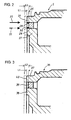
- the inner diameter at the front end portion of the large-diameter rear housing member 26 and the outer diameter at the front end portion of the small-diameter rear housing member 27 are formed or machined to be substantially equal respectively to the outer and inner diameters of the intermediate member 28.
- the intermediate member 28 is interposed and fit between the large and small-diameter rear housing members 26, 27 and is held at such a position that the front end surface thereof retracts or recedes by a second predetermined value (L2) within the range of, preferably, 0.2 through 2 millimeters from the front end surfaces of the large and small-diameter rear housing members 26, 27.
- L2 second predetermined value
- an electron beam 35 is emitted from the front side of the assembly toward each of the fitting portions of the intermediate member 28 with the large and small-diameter rear housing members 26, 27 in the direction of the rotational axis 0.
- the inner circumferential edge portion of the large-diameter rear housing member 26 and the outer circumferential edge portion of the intermediate member 28 are melted and fused together to be deposited as the bead weld 29 around the outer circumferential edge portion of the intermediate member 28, and the outer circumferential edge portion of the small-diameter rear housing member 27 and the inner circumferential edge portion of the intermediate member 28 are melted and fused together to be deposited as the bead weld 30 around the inner circumferential edge portion of the intermediate member 28.
- the electron beam welding is performed between the outer circumferential edge portion of the intermediate member 28 and the inner circumferential edge portion of the large-diameter rear housing member 26 as well as between the inner circumferential edge portion of the intermediate member 28 and the outer circumferential edge portion of the small-diameter rear housing member 27.
- the welding is carried out so that no connection is made across the beard welds 29, 30 which are fused by welding from parts of the large and small-diameter rear housing members 26, 27 to be deposited around the outer and inner circumferential edge portions of the intermediate member 28.
- the clutch contact surface 31 is formed by performing the cutting so that the distance between the front end surfaces of the large and small-diameter rear housing members 26, 27 and the front end surface of the intermediate member 28 becomes the first predetermined value (L1) such as within the range of 0.1 through 1 millimeter, preferably.
- the welding of the intermediate member 28 to the large and small-diameter rear housing members 26, 27 can be done by emitting, instead of the electron beam 35, a laser beam from the front side of the assembly toward each of the fitting portions of the intermediate member 28 with the large and small-diameter rear housing members 26, 27 in the direction of the rotational axis 0.
- the intermediate member 28 and the large and small-diameter rear housing members 26, 27 may be welded otherwise than as described above.
- an electromagnetic clutch 34 in the second embodiment according to the present invention will be described hereafter with reference to Figure 3.
- the electromagnetic clutch 34 in the second embodiment is different only in the rear housing from that in the first embodiment, and those in the first ant second embodiments take the same configuration in other components.
- the following description will be directed only to the rear housing 36 constituting a magnetic path forming member.
- the inner diameter at the front end portion of a large-diameter rear housing member 37 as a large-diameter cylindrical member and the outer diameter at the front end portion of a small-diameter rear housing member 38 as a small-diameter cylindrical member are formed or machined to be substantially equal respectively to the outer and inner diameters of the intermediate member 39.
- the front end surface of the intermediate member 39 recedes or retracts by the second predetermined distance (L2) within the range of, preferably, 0.2 through 2 millimeters from the front end surfaces of the large and small-diameter rear housing members 37, 38, in which state a soldering is performed to make connections between the outer surface of the intermediate member 39 and the inner surface of the large-diameter rear housing member 37 as well as between the inner surface of the intermediate member 39 and the outer surface of the small-diameter rear housing member 38.
- L2 second predetermined distance
- a clutch contact surface 40 is formed by cutting the front end surfaces of the large and small-diameter rear housing members 37, 38 so that the distance between the front end surfaces of the large and small-diameter rear housing members 37, 38 and the front end surface of the intermediate member 39 becomes the first predetermined value (L1) such as within the range of 0.1 through 1 millimeter, preferably.
- L1 the first predetermined value
- Each of the large and small-diameter rear housing members 37, 38 is made of a magnetic metal such as iron or the like, while the intermediate member 39 is made of a non-magnetic metal such as stainless steel, copper or the like.
- the pilot clutch 20 is interposed between the clutch contact surface 40 formed at the front end surface of the rear housing 36 and the armature 23, and the electromagnet 24 is arranged between the large and small-diameter rear housing members 37, 38 behind the rear housing 36, so that the electromagnetic clutch 34 is constituted.
- the intermediate member 39 may be made of a non-magnetic nonmetal such as resin or the like, in which case a suitable adhesive or cement may be employed to join or connect the intermediate member 39 with the large and small-diameter rear housing members 37, 38.
- the intermediate member 28 (or 39) is held or positioned to recede by the second predetermined distance (L2) from the front end surfaces of the large and small-diameter cylindrical members 26, 27 (or 37, 38) when joined to these members 26, 27 (or 37, 38).
- L2 the second predetermined distance
- L1 the first predetermined distance
- the clutch contact surface 31 is formed by cutting the front end surfaces of the large and small-diameter cylindrical portions 26, 27 and the portions 29, 30 which are melted and fused from parts of the large and small-diameter cylindrical portions 27, 28 to be deposited onto the intermediate member 28, the large and small-diameter cylindrical portions 27, 28 can be given magnetic paths which are separated by the non-magnetic member 28 and sufficiently large in respective areas for magnetic flux, and the clutch contact surface 31 can be improved in flatness in addition to being given the magnetic paths with the sufficiently large areas for magnetic flux.
- the outer and inner circumferential edges of the intermediate member 28 are joined by the electron beam welding respectively to the inner circumferential edge of the large-diameter cylindrical portion 26 and the outer circumferential edge of the small-diameter cylindrical portion 27. Therefore, it can be realized that the large and small-diameter cylindrical portions 26, 27 can be accurately welded by the electron beam welding to the outer and inner circumferential edges of the intermediate member 28.
- the outer and inner circumferential edges of the intermediate member 28 are joined by the laser beam welding respectively to the inner circumferential edge of the large-diameter cylindrical portion 26 and the outer circumferential edge of the small-diameter cylindrical portion 27. Therefore, it can be realized that the large and small-diameter cylindrical portions 26, 27 can be accurately welded by the laser beam welding to the outer and inner circumferential edges of the intermediate member 28.
- the distance (L1) between the clutch contact surface 31, formed by cutting the front end surfaces of the large and small-diameter cylindrical portions 26, 27, and the receding front end surface of the intermediate member 28 is determined to be chosen within the range of 0.1 through 1 millimeter. Since the distance (L1) between the clutch contact surface 31 and the front end surface of the intermediate member 28 is determined to be within the range of 01. through 1 millimeter, it can be realized to easily form the clutch contact surface 31 which is sufficiently high in rigidity as well as good in flatness.
- the intermediate member 28 is positioned relative to the large and small-diameter cylindrical portions 26, 27 with the front end surface of the former receding or retracting by the first predetermined distance (L1) from the front end surfaces of the latter, in which state the outer and inner circumferential edges of the large and small-diameter cylindrical portions 26, 27 are welded respectively to the outer and inner circumferential edges of the intermediate member 28. Then, cutting is performed on the front end surfaces of the large and small-diameter cylindrical portions 26, 27 as well as on the portions which are melted and fused by welding from the parts of the large and small-diameter cylindrical portions 26, 27 to be deposited onto the intermediate member 28.
- the large and small-diameter cylindrical portions 26, 27 can be given magnetic paths which are separated by the non-magnetic member 28 and sufficiently large in respective areas for magnetic flux, and the clutch contact surface 31 can be improved in flatness in addition to being given the magnetic paths with the sufficiently large areas for magnetic flux.
- the large and small-diameter cylindrical portions 37, 38 can be given magnetic paths which are separated by the non-magnetic member 39 having a thickness required to manufacture and sufficiently large in respective areas for magnetic flux, and the clutch contact surface 40 can be improved in flatness in addition to being given the magnetic paths with the sufficiently large areas for magnetic flux.
- the outer and inner surfaces of the intermediate member 39 are joined by either of welding, soldering and adhesive respectively to the inner surface of the large-diameter cylindrical portion 37 and the outer surface of the small-diameter cylindrical portion 38. Since the large and small-diameter cylindrical portions 37, 38 are joined by either of welding, soldering and adhesive to the intermediate member 39, the magnetic path forming member 5 can be easily manufactured at a low cost.
- An electromagnetic clutch having a magnetic path forming member with a clutch contact surface which is large in area for magnetic path as well as good in flatness.
- the electromagnetic clutch is provided to be of the type that a first magnetic member with a large-diameter cylindrical portion made of a magnetic metal and a second magnetic member with a small-diameter cylindrical portion made of a magnetic metal and contained in the large-diameter cylindrical portion are bodily joined to an annular member of a non-magnetic material interposed between the large and small-diameter cylindrical portions to constitute a magnetic path forming member.
- a friction clutch is arranged between a clutch contact surface formed at the front end surface of the magnetic path forming member and an armature, while an electromagnet is arranged behind the magnetic path forming member for generating magnetic flux between the large and small-diameter cylindrical portions.
- the outer and inner circumferential edges of the annular member are joined by welding respectively to the inner circumferential edge of the large-diameter cylindrical portion and the outer circumferential edge of the small-diameter cylindrical portion, with the front end surface of the annular member receding a second predetermined distance (L2) from the front end surfaces of the large and small-diameter cylindrical portions.
- the clutch contact surface is formed by cutting the front end surfaces of the large and small-diameter cylindrical portions until the distance which the front end surface of the annular member recedes from the front end surfaces of the large and small-diameter cylindrical portions becomes a first predetermined distance (L1).
Landscapes
- Engineering & Computer Science (AREA)
- General Engineering & Computer Science (AREA)
- Physics & Mathematics (AREA)
- Electromagnetism (AREA)
- Mechanical Engineering (AREA)
- Mechanical Operated Clutches (AREA)
- Braking Arrangements (AREA)
Applications Claiming Priority (2)
| Application Number | Priority Date | Filing Date | Title |
|---|---|---|---|
| JP2003139880A JP2004340317A (ja) | 2003-05-19 | 2003-05-19 | 電磁クラッチおよび電磁クラッチの磁路形成部材の製造方法 |
| JP2003139880 | 2003-05-19 |
Publications (2)
| Publication Number | Publication Date |
|---|---|
| EP1479935A2 true EP1479935A2 (de) | 2004-11-24 |
| EP1479935A3 EP1479935A3 (de) | 2005-07-20 |
Family
ID=33095372
Family Applications (1)
| Application Number | Title | Priority Date | Filing Date |
|---|---|---|---|
| EP04011827A Withdrawn EP1479935A3 (de) | 2003-05-19 | 2004-05-18 | Elektromagnetische Kupplung und Herstellungsverfahren für das den Magnetkreis bildende Element |
Country Status (4)
| Country | Link |
|---|---|
| US (1) | US7070034B2 (de) |
| EP (1) | EP1479935A3 (de) |
| JP (1) | JP2004340317A (de) |
| KR (1) | KR20040100901A (de) |
Families Citing this family (6)
| Publication number | Priority date | Publication date | Assignee | Title |
|---|---|---|---|---|
| JP4761767B2 (ja) * | 2004-12-24 | 2011-08-31 | Gknドライブラインジャパン株式会社 | 磁路形成部材、磁路形成部材を用いた電磁連結装置及び、磁路形成部材の製造方法 |
| JP2010242830A (ja) * | 2009-04-03 | 2010-10-28 | Jtekt Corp | 電磁クラッチ |
| CN102434264B (zh) * | 2011-10-27 | 2014-03-12 | 龙口中宇机械有限公司 | 电磁风扇离合器传动盘制造方法、模具及制造的传动盘 |
| JP5974711B2 (ja) * | 2012-07-31 | 2016-08-23 | 株式会社ジェイテクト | 駆動力伝達装置の製造方法 |
| JP6204485B2 (ja) * | 2013-10-17 | 2017-09-27 | Gknドライブラインジャパン株式会社 | 摩擦ロスを低減したクラッチ装置およびデファレンシャル装置 |
| US9651097B2 (en) | 2015-03-24 | 2017-05-16 | American Axle & Manufacturing, Inc. | Friction clutch assembly |
Citations (1)
| Publication number | Priority date | Publication date | Assignee | Title |
|---|---|---|---|---|
| JP2000230577A (ja) | 1999-02-12 | 2000-08-22 | Toyoda Mach Works Ltd | 電磁クラッチの磁路形成部材 |
Family Cites Families (9)
| Publication number | Priority date | Publication date | Assignee | Title |
|---|---|---|---|---|
| US2860403A (en) * | 1953-06-30 | 1958-11-18 | Warner Electric Brake & Clutch | Method of making a pole piece unit for magnets |
| US2739684A (en) * | 1955-01-21 | 1956-03-27 | Warner Electric Brake & Clutch | Pole piece unit for magnets |
| JPS5520905A (en) | 1978-07-28 | 1980-02-14 | Hitachi Ltd | Electromagnetic clutch |
| US4508203A (en) * | 1982-07-19 | 1985-04-02 | Facet Enterprises, Incorporated | Plastic bobbin for electromagnetic clutch |
| US4685202A (en) * | 1986-01-13 | 1987-08-11 | Dana Corporation | Method of forming a coupling disc for an electromagnetic coupling |
| US5791039A (en) * | 1993-03-18 | 1998-08-11 | Nippondenso Co., Ltd. | Method for manufacturing a rotor of a magnetic clutch |
| EP0856676B8 (de) * | 1997-01-29 | 2005-01-12 | Toyota Jidosha Kabushiki Kaisha | Kupplungseinheit |
| JP3243437B2 (ja) | 1997-11-21 | 2002-01-07 | 豊田工機株式会社 | 駆動力伝達装置 |
| US5920981A (en) | 1997-03-25 | 1999-07-13 | Dana Corporation | Method of manufacturing a rotor for an electromagnetic clutch assembly |
-
2003
- 2003-05-19 JP JP2003139880A patent/JP2004340317A/ja active Pending
-
2004
- 2004-05-07 KR KR1020040032227A patent/KR20040100901A/ko not_active Withdrawn
- 2004-05-18 EP EP04011827A patent/EP1479935A3/de not_active Withdrawn
- 2004-05-18 US US10/847,381 patent/US7070034B2/en not_active Expired - Lifetime
Patent Citations (1)
| Publication number | Priority date | Publication date | Assignee | Title |
|---|---|---|---|---|
| JP2000230577A (ja) | 1999-02-12 | 2000-08-22 | Toyoda Mach Works Ltd | 電磁クラッチの磁路形成部材 |
Also Published As
| Publication number | Publication date |
|---|---|
| KR20040100901A (ko) | 2004-12-02 |
| US20040231948A1 (en) | 2004-11-25 |
| JP2004340317A (ja) | 2004-12-02 |
| US7070034B2 (en) | 2006-07-04 |
| EP1479935A3 (de) | 2005-07-20 |
Similar Documents
| Publication | Publication Date | Title |
|---|---|---|
| US7764154B2 (en) | Electronically actuated apparatus using solenoid actuator with integrated sensor | |
| US8262491B2 (en) | Driveshaft assembly and method for assembling driveshaft assembly | |
| JP6196271B2 (ja) | 溶接構造及び溶接構造の製造方法 | |
| JP5604212B2 (ja) | 電磁式駆動ユニットおよびその製造方法 | |
| JP2013512402A (ja) | 差動アセンブリ及び差動アセンブリを備えた駆動アセンブリ | |
| US7070034B2 (en) | Electromagnetic clutch and manufacturing method of magnetic path forming member therefor | |
| JPWO2015080133A1 (ja) | 流体継手の製造方法及び流体継手 | |
| US20100119300A1 (en) | Outer joint member for constant velocity universal joint | |
| JP2009109020A (ja) | 電磁クラッチを用いた駆動力伝達装置の組立方法 | |
| US9169880B2 (en) | Driving force transmission apparatus and method of manufacturing the same | |
| US12222026B2 (en) | Electromagnetic actuating device and transmission system provided with said electromagnetic actuating device | |
| EP1524447B1 (de) | Antriebskraft-Übertragungseinrichtung | |
| JP2009250426A (ja) | 電磁弁およびその製造方法 | |
| JP4096679B2 (ja) | 磁路形成部材の製造方法 | |
| JP6467268B2 (ja) | 遊星歯車機構 | |
| JP5511522B2 (ja) | 非磁性材を備えたローター及びこのローターを用いた動力伝達装置、ローターの製造方法 | |
| JP2007170623A (ja) | 磁束漏れ防止材料の接合構造及び磁束漏れ防止材料の接合方法及びこれらを用いた電磁クラッチ装置 | |
| JP7254566B2 (ja) | 等速ジョイントに用いられる継手部材の製造方法及び継手部材 | |
| JP3784040B2 (ja) | 車両用駆動力伝達装置 | |
| JP7605008B2 (ja) | 車両のデファレンシャル装置 | |
| JP3574756B2 (ja) | 電磁クラッチの磁路形成部材 | |
| JP2002039216A (ja) | 連結シャフトおよび同連結シャフトを構成部材とする駆動力伝達装置 | |
| JP2010276178A (ja) | 滑り軸受、滑り軸受を備えた動力伝達装置、及び滑り軸受の形成方法 | |
| JP2020085161A (ja) | 等速自在継手に用いられる外側継手部材の製造方法及び外側継手部材 | |
| JP2002181080A (ja) | 駆動力伝達装置 |
Legal Events
| Date | Code | Title | Description |
|---|---|---|---|
| PUAI | Public reference made under article 153(3) epc to a published international application that has entered the european phase |
Free format text: ORIGINAL CODE: 0009012 |
|
| AK | Designated contracting states |
Kind code of ref document: A2 Designated state(s): AT BE BG CH CY CZ DE DK EE ES FI FR GB GR HU IE IT LI LU MC NL PL PT RO SE SI SK TR |
|
| AX | Request for extension of the european patent |
Extension state: AL HR LT LV MK |
|
| PUAL | Search report despatched |
Free format text: ORIGINAL CODE: 0009013 |
|
| AK | Designated contracting states |
Kind code of ref document: A3 Designated state(s): AT BE BG CH CY CZ DE DK EE ES FI FR GB GR HU IE IT LI LU MC NL PL PT RO SE SI SK TR |
|
| AX | Request for extension of the european patent |
Extension state: AL HR LT LV MK |
|
| RIC1 | Information provided on ipc code assigned before grant |
Ipc: 7F 16D 27/14 B Ipc: 7F 16D 27/115 A |
|
| 17P | Request for examination filed |
Effective date: 20060109 |
|
| AKX | Designation fees paid |
Designated state(s): DE FR GB |
|
| RAP1 | Party data changed (applicant data changed or rights of an application transferred) |
Owner name: JTEKT CORPORATION |
|
| RIN1 | Information on inventor provided before grant (corrected) |
Inventor name: KAMIYA, KOJI Inventor name: HARADA, HIROKAZU Inventor name: SUZUKI, KUNIHIKO |
|
| STAA | Information on the status of an ep patent application or granted ep patent |
Free format text: STATUS: THE APPLICATION IS DEEMED TO BE WITHDRAWN |
|
| 18D | Application deemed to be withdrawn |
Effective date: 20080701 |