EP1479913A2 - Roots-Pumpe - Google Patents
Roots-Pumpe Download PDFInfo
- Publication number
- EP1479913A2 EP1479913A2 EP04011826A EP04011826A EP1479913A2 EP 1479913 A2 EP1479913 A2 EP 1479913A2 EP 04011826 A EP04011826 A EP 04011826A EP 04011826 A EP04011826 A EP 04011826A EP 1479913 A2 EP1479913 A2 EP 1479913A2
- Authority
- EP
- European Patent Office
- Prior art keywords
- passage
- confluent
- rotors
- confluent passage
- paired
- Prior art date
- Legal status (The legal status is an assumption and is not a legal conclusion. Google has not performed a legal analysis and makes no representation as to the accuracy of the status listed.)
- Granted
Links
- 230000002093 peripheral effect Effects 0.000 claims abstract description 37
- 239000007789 gas Substances 0.000 description 24
- 239000007795 chemical reaction product Substances 0.000 description 11
- 238000004891 communication Methods 0.000 description 4
- 238000004519 manufacturing process Methods 0.000 description 4
- 238000009825 accumulation Methods 0.000 description 3
- 230000000694 effects Effects 0.000 description 3
- 239000004065 semiconductor Substances 0.000 description 2
- 230000008878 coupling Effects 0.000 description 1
- 238000010168 coupling process Methods 0.000 description 1
- 238000005859 coupling reaction Methods 0.000 description 1
- 230000007423 decrease Effects 0.000 description 1
- 238000000034 method Methods 0.000 description 1
- 238000005121 nitriding Methods 0.000 description 1
- 238000005192 partition Methods 0.000 description 1
Images


Classifications
-
- F—MECHANICAL ENGINEERING; LIGHTING; HEATING; WEAPONS; BLASTING
- F04—POSITIVE - DISPLACEMENT MACHINES FOR LIQUIDS; PUMPS FOR LIQUIDS OR ELASTIC FLUIDS
- F04C—ROTARY-PISTON, OR OSCILLATING-PISTON, POSITIVE-DISPLACEMENT MACHINES FOR LIQUIDS; ROTARY-PISTON, OR OSCILLATING-PISTON, POSITIVE-DISPLACEMENT PUMPS
- F04C18/00—Rotary-piston pumps specially adapted for elastic fluids
- F04C18/08—Rotary-piston pumps specially adapted for elastic fluids of intermeshing-engagement type, i.e. with engagement of co-operating members similar to that of toothed gearing
- F04C18/12—Rotary-piston pumps specially adapted for elastic fluids of intermeshing-engagement type, i.e. with engagement of co-operating members similar to that of toothed gearing of other than internal-axis type
- F04C18/126—Rotary-piston pumps specially adapted for elastic fluids of intermeshing-engagement type, i.e. with engagement of co-operating members similar to that of toothed gearing of other than internal-axis type with radially from the rotor body extending elements, not necessarily co-operating with corresponding recesses in the other rotor, e.g. lobes, Roots type
-
- F—MECHANICAL ENGINEERING; LIGHTING; HEATING; WEAPONS; BLASTING
- F16—ENGINEERING ELEMENTS AND UNITS; GENERAL MEASURES FOR PRODUCING AND MAINTAINING EFFECTIVE FUNCTIONING OF MACHINES OR INSTALLATIONS; THERMAL INSULATION IN GENERAL
- F16B—DEVICES FOR FASTENING OR SECURING CONSTRUCTIONAL ELEMENTS OR MACHINE PARTS TOGETHER, e.g. NAILS, BOLTS, CIRCLIPS, CLAMPS, CLIPS OR WEDGES; JOINTS OR JOINTING
- F16B15/00—Nails; Staples
- F16B15/02—Nails; Staples with specially-shaped heads, e.g. with enlarged surfaces
-
- F—MECHANICAL ENGINEERING; LIGHTING; HEATING; WEAPONS; BLASTING
- F04—POSITIVE - DISPLACEMENT MACHINES FOR LIQUIDS; PUMPS FOR LIQUIDS OR ELASTIC FLUIDS
- F04C—ROTARY-PISTON, OR OSCILLATING-PISTON, POSITIVE-DISPLACEMENT MACHINES FOR LIQUIDS; ROTARY-PISTON, OR OSCILLATING-PISTON, POSITIVE-DISPLACEMENT PUMPS
- F04C23/00—Combinations of two or more pumps, each being of rotary-piston or oscillating-piston type, specially adapted for elastic fluids; Pumping installations specially adapted for elastic fluids; Multi-stage pumps specially adapted for elastic fluids
- F04C23/001—Combinations of two or more pumps, each being of rotary-piston or oscillating-piston type, specially adapted for elastic fluids; Pumping installations specially adapted for elastic fluids; Multi-stage pumps specially adapted for elastic fluids of similar working principle
-
- F—MECHANICAL ENGINEERING; LIGHTING; HEATING; WEAPONS; BLASTING
- F04—POSITIVE - DISPLACEMENT MACHINES FOR LIQUIDS; PUMPS FOR LIQUIDS OR ELASTIC FLUIDS
- F04C—ROTARY-PISTON, OR OSCILLATING-PISTON, POSITIVE-DISPLACEMENT MACHINES FOR LIQUIDS; ROTARY-PISTON, OR OSCILLATING-PISTON, POSITIVE-DISPLACEMENT PUMPS
- F04C2250/00—Geometry
- F04C2250/10—Geometry of the inlet or outlet
-
- F—MECHANICAL ENGINEERING; LIGHTING; HEATING; WEAPONS; BLASTING
- F04—POSITIVE - DISPLACEMENT MACHINES FOR LIQUIDS; PUMPS FOR LIQUIDS OR ELASTIC FLUIDS
- F04C—ROTARY-PISTON, OR OSCILLATING-PISTON, POSITIVE-DISPLACEMENT MACHINES FOR LIQUIDS; ROTARY-PISTON, OR OSCILLATING-PISTON, POSITIVE-DISPLACEMENT PUMPS
- F04C2280/00—Arrangements for preventing or removing deposits or corrosion
- F04C2280/02—Preventing solid deposits in pumps, e.g. in vacuum pumps with chemical vapour deposition [CVD] processes
Definitions
- the present invention relates to a roots pump having a plurality of rotary shafts arranged in parallel relation to each other and a rotor arranged on each of the rotary shafts, wherein the rotors on any two adjacent rotary shafts are engaged with each other and a set of engaged rotors are accommodated in a pump chamber which is formed in the roots pump.
- a roots pump or a kind of vacuum pump, as disclosed in Unexamined Japanese Patent Publication No. 2002-221178, a set of two rotors are rotated in engagement with each other. The rotation of the two engaged rotors transfers gas while simultaneously compressing the same.
- the roots pump having plural sets of such two rotors has a passage formed in an end wall which partitions any two adjacent pump chambers which are arranged in the axial direction of the rotary shaft for transferring the gas from a large-volume pump chamber to a smaller-volume pump chamber.
- the roots pump has a closed space formed between the rotor and a peripheral wall surface of the pump chamber facing the rotor, and such closed space communicates with the other closed space formed between the other rotor and the other peripheral wall surface of the same pump chamber facing the other rotor.
- the passage in the end wall communicates with this confluent space (a confluent passage in the present invention), and gas in the confluent space flows into the passage in the end wall.
- reaction product flows into the roots pump with gas.
- this reaction product is accumulated in a pump chamber of the roots pump, operation of the roots pump may become disabled. Therefore, there has been a need for preventing reaction product from being accumulated in a roots pump.
- a roots pump has a housing, a plurality of rotary shafts, a rotor, a confluent passage and a closed space.
- the housing forms therein a pump chamber.
- the rotary shafts are supported on the housing in parallel relation to each other.
- the rotor is mounted on each of the rotary shafts, and the rotors on any adjacent rotary shafts are in engagement with each other.
- a set of the engaged rotors is accommodated in the pump chamber.
- the confluent passage is formed along one crossing line of paired imaginary swept peripheral surfaces in one-to-one correspondence with the paired and engaged rotors.
- the closed space is formed in one-to-one correspondence with each of the paired rotors between the paired rotors and paired peripheral wall surfaces which form the pump chamber.
- the closed space initially joins the confluent passage from a terminal end of the confluent passage with rotation of the paired rotors.
- FIGS. 1 through 8B A first preferred embodiment of a roots pump 10 according to the present invention will now be described with reference to FIGS. 1 through 8B.
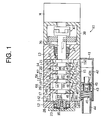
- the roots pump or a kind of vacuum pump 10 has a rotor housing 11, a front housing 12 connected to the front end of the rotor housing 11 and a rear housing 13 connected to the rear end of the rotor housing 11. These rotor housing 11, front housing 12 and rear housing 13 cooperate to form the housing of the roots pump 10. It is noted that the upper side and the lower side of FIG. 1 correspond to the upper side and the lower side of the roots pump 10, respectively.
- the rotor housing 11 includes a cylinder block 14 forming integrally therewith a plurality of wall elements 141 and a cylinder block 15 forming integrally therewith a plurality of wall elements 151.
- the wall elements 141, 151 are paired, respectively, and each paired wall elements 141, 151 cooperates to form an end wall 16.
- a space between the front housing 12 and the end wall 16 and spaces between any two adjacent end walls 16 are defined as pump chambers 17, 18, 19, 20, respectively.
- a space between the rear housing 13 and the end wall 16 is defined as a pump chamber 21.
- the pump chambers 17, 18, 19, 20, 21 are formed such that the widths thereof are reduced progressively in this order.
- the front housing 12 and the rear housing 13 rotatably support a rotary shaft 22 through radial bearings 23, 24, respectively.
- the front housing 12 and the rear housing 13 rotatably support a rotary shaft 25 through radial bearings 26, 27, respectively.
- the rotary shafts 22, 25 are arranged in parallel relation to each other, extending through the end walls 16.
- the rotary shaft 22 has a plurality of rotors 28, 29, 30, 31, 32 formed integrally therewith.
- the rotary shaft 25 has also a plurality of rotors 33, 34, 35, 36, 37 formed integrally therewith.
- the number of the rotors formed with the rotary shaft 25 is equal to that with the rotary shaft 22.
- the rotors 28 through 32 have similar shape and size as seen in the direction of the axis 221 of the rotary shaft 22.
- the rotors 33 through 37 have similar shape and size as seen in the direction of the axis 251 of the rotary shaft 25.
- the thicknesses of the rotors 28, 29, 30, 31, 32 reduce in this order, and the thicknesses of the rotors 33, 34, 35, 36, 37 also reduce in this order.
- the rotors 28, 33 are accommodated in the pump chamber 17 in engagement with each other with a slight clearance formed therebetween.
- the rotors 29, 34 are accommodated in the pump chamber 18 in similar engagement with each other.
- the rotors 30, 35, the rotors 31, 36, and the rotors 32, 37 are accommodated in the pump chamber 19, 20 and 21, respectively.
- the volumes of the pump chambers 17 through 21 reduce progressively in this order.
- the rotors 28, 33 sweep or pass over the surfaces of inner peripheral walls 59, 60, which form the pump chamber 17, at a slight distance therefrom.
- the rotors 29, 34; 30, 35; 31, 36; and 32, 37 pass similarly over the surfaces of the inner peripheral walls 61, 62; 63, 64; 65, 66 and 67, 68 which form the pump chambers 18, 19, 20 and 21, respectively.
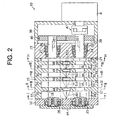
- the roots pump 10 further includes a gear housing 38 assembled to the rear housing 13.
- the rotary shafts 22, 25 extend through the rear housing 13 and protrude into the gear housing 38.
- Gears 39, 40 are secured to the protruding ends of the rotary shafts 22, 25, respectively, for engagement with each other.
- An electric motor M is assembled to the gear housing 38, and driving power of the electric motor M is transmitted to the rotary shaft 22 through a shaft coupling 47 thereby to rotate the rotary shaft 22 in the direction indicated by the arrow R1 in FIGS. 3 through 6.
- the rotary shaft 25 receives the driving power of the electric motor M through the gears 39, 40 thereby to be rotated in reverse direction of the rotary shaft 22, or in the direction indicated by the arrow R2 in FIGS. 3 through 6.
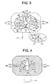
- a circular arc C1 illustrated in FIG. 3 shows a region of imaginary peripheral surface which is swept by the rotor 28 during its rotation
- a circular arc C2 shows a region of imaginary peripheral surface which is swept by the rotor 33 during its rotation.
- the imaginary peripheral surfaces indicated by the circular arcs C1, C2 are referred to as swept peripheral surfaces C1, C2 hereinafter.
- These two circular arcs or swept peripheral surfaces C1, C2 intersect at two points S and U as seen in FIG. 3 (actually S and U being imaginary crossing lines extending perpendicularly to the plane of the drawing of FIG. 3 and one of such imaginary lines S being shown in FIG. 7.)
- the pump chamber 17 forms therein a confluent passage 49 which extends along the crossing line S.
- the confluent passage 49 is located at a region which is adjacent to the crossing line S and surrounded by the swept peripheral surfaces C1, C2 and the peripheral wall surface which forms the pump chamber 17.
- the pump chamber 17 also forms therein a splitting passage 50 which extends along the other of the intersections, which is denoted by U.
- the splitting passage 50 is located at a region which is adjacent to the crossing line U and surrounded by the swept peripheral surfaces C1, C2 and the peripheral wall surface which forms the pump chamber 17.
- the pump chambers 18 through 21 also forms therein confluent passages 51, 52, 53, 54, and also splitting passages 55, 56, 57, 58, respectively.
- the swept peripheral surfaces C1, C2 are illustrated in the pump chambers 18 through 21, as shown in FIGS. 5 and 6.
- a passage surface 491 of the confluent passage 49 has a planar shape and an inclined plane which declines from the side of the front housing 12 toward the side of the rear housing 13.
- passage surfaces 511, 521, 531 of the confluent passages 51, 52, 53 also have a planar shape and inclined planes which decline from the side of the front housing 12 toward the side of the rear housing 13, respectively.
- FIGS. 8A and 8B show the passage surfaces 491, 511, 521, 531 of the confluent passages 49, 51, 52, 53, respectively.
- the passage surface 491 is located higher than the lowest portion 591 of the peripheral wall surface 59 corresponding to the rotor 28 and is also located higher than the lowest portion 601 of the peripheral wall surface 60 corresponding to the rotor 33.
- the passage surface 511 is located higher than the lowest portion 611 of the peripheral wall surface 61 corresponding to the rotor 29 and is also located higher than the lowest portion 621 of the peripheral wall surface 62 corresponding to the rotor 34.
- the passage surface 521 is located higher than the lowest portion 631 of the peripheral wall surface 63 corresponding to the rotor 30 and is also located higher than the lowest portion 641 of the peripheral wall surface 64 corresponding to the rotor 35.
- the passage surface 531 is located higher than the lowest portion 651 of the peripheral wall surface 65 corresponding to the rotor 31 and is also located higher than the lowest portion 661 of the peripheral wall surface 66 corresponding to the rotor 36.
- the passage surfaces 491, 511, 521, 531 of the confluent passages 49, 51, 52, 53 form part of the wall surfaces which form the pump chambers 17, 18, 19, 20, respectively.
- the passage surfaces 491, 511, 521, 531 of the respective confluent passages 49, 51, 52, 53 connect with the peripheral wall surfaces 59 through 66, respectively.
- Side edges 492, 493 of the passage surface 491 are connections between the passage surface 491 of the confluent passage 49 and the peripheral wall surfaces 59, 60, respectively.
- the planar passage surface 491 declines from the side of the front housing 12 toward the side of the rear housing 13 and is also located higher than the lowest portions 591, 601 of the peripheral wall surfaces 59, 60. Accordingly, the side edges 492, 493 of the passage surface 491 are spaced apart from each other increasingly from the side of the front housing 12 toward the side of the rear housing 13.
- the width of the confluent passage 49 is widened progressively from the side of the front housing 12 toward the side of the rear housing 13, and the width of the confluent passage 49 at its terminal end 495 is greater than that at the starting end 494.
- the widths of the confluent passages 51 through 53 that is, the widths of the passage surfaces 511 through 531, are also widened increasingly from the side of the front housing 12 toward the side of the rear housing 13.
- the end wall 16 forms therein a passage 48.
- the end wall 16 also forms therein an inlet 481 and an outlet 482 of the passage 48.
- the confluent passages 49, 51, 52, 53 communicate with the inlets 481 of the passages 48, respectively, and any two adjacent pump chambers 17, 18, 19, 20, 21 are in communication with each other through the passage 48 in the end wall 16, respectively.
- Each passage 48 has an inclined surface 483 formed at its bottom. The inclined surface 483 declines from the side of the rear housing 13 toward the side of the front housing 12. The inclined surface 483 of the passage 48 connecting with the confluent passage 49 continues into the passage surface 491 of the confluent passage 49.
- a closed space P1 is formed between the rotor 28 and the peripheral wall surface 59 which forms the pump chamber 17, and a closed space P2 is formed between the rotor 28 and the peripheral wall surface 60 which forms the pump chamber 17 and the rotor 33.
- the closed spaces P1, P2 moving from the splitting passage 50 toward the confluent passage 49 with rotation of the rotors 28, 33 meet each other at the confluent passage 49.
- similar closed spaces are formed in the other pump chambers 18 through 21, as indicated by P1, P2 in FIGS. 5 and 6.
- the cylinder block 14 forms therein a suction port 142 which communicates with the splitting passage 50 of the pump chamber 17.
- the cylinder block 15 forms therein an exhaust port 152 which communicates with the confluent passage 54 of the pump chamber 21.
- a flange 41 is connected to the exhaust port 152.
- a muffler 42 is connected to the flange 41, and a guide pipe 43 is connected to the muffler 42.
- an exhaust pipe 44 is connected to the guide pipe 43.
- the exhaust pipe 44 is connected to an exhaust gas treatment device (not shown).
- the guide pipe 43 accommodates therein a valve body 45 and a return spring 46.
- the guide pipe 43 forms therein a tapered valve hole 431, and the valve body 45 is operable to open and close the valve hole 431.
- the return spring 46 urges the valve body 45 in the direction which causes the valve hole 431 to be closed.
- the guide pipe 43, the valve body 45 and the return spring 46 cooperatively serve as a means for preventing reverse flow of gas.
- the rotary shafts 22, 25 rotate and, therefore, gas in an external vacuum target region (not shown) is introduced into the pump chamber 17 through the suction port 142.
- the gas introduced into the splitting passage 50 of the pump chamber 17 through the suction port 142 is taken into the closed spaces P1, P2 and then transferred toward the confluent passage 49 by rotation of the rotors 28, 33.
- the gas sent to the confluent passage 49 flows from the inlet 481 of the end wall 16 into the exhaust passage 48 and then transferred to the splitting passage 55 of the next (or downstream) pump chamber 18 through the outlet 482.
- the gas is transferred from one pump chamber to another in the order in which the volume of the pump chambers reduce, that is, in the order of the pump chambers 18, 19, 20, 21.
- the gas introduced into the pump chamber 17 is transferred therefrom to the pump chambers 18 through 21 one after another while being compressed.
- the gas transferred into the pump chamber 21 is then exhausted to the exhaust gas treatment device through the exhaust port 152, the flange 41, the muffler 42 and the backflow preventing means.
- Each of the confluent passages 49, 51, 52, 53 has a front end on the side of the front housing 12 and a rear end on the side of the rear housing 13, as represented by the starting end 494 and the terminal end 495 of the confluent passage 49 as shown in FIG. 7.
- the inlets 481 of the passages 48 in the end walls 16 continue into the confluent passages 49, 51, 52, 53, respectively.
- the rear ends of the confluent passages 49, 51, 52, 53 correspond to the communication sides of the passages 48 of the pump chambers 17 thorough 20.
- the following advantageous effects are obtained. It is noted that the effects will be mentioned with reference to only the confluent passage 49, but similar effects are obtainable from the other confluent passages 49, 51, 52, 53.
- the gas in the closed spaces P1, P2 simultaneously flows into the confluent passage 49 from both the starting end 494 and the terminal end 495 of the confluent passage 49.
- Such inflow tends to cause stagnation of the gas adjacent to the starting end 494 of the confluent passage 49 and, therefore, reaction product tends to be accumulated at the point of stagnation when the roots pump 10 is used as a vacuum pump in film production process for manufacturing semiconductors.
- planar passage surface 491 declines from the starting end 494 of the confluent passage 49 toward the terminal end 495 thereof.
- the side edges 492, 493 of the passage surface 491 extend from the starting end 494 of the confluent passage 49 toward the terminal end 495 thereof while being spaced further away from the crossing line S. Therefore, the closed space P1 on the side of the rotor 28 and the closed space P2 on the side of the rotor 33 initiate to join the confluent passage 49 from the terminal end 495 of the confluent passage 49.
- the planar passage surface 491 of the confluent passage 49 declines from the starting end 494 of the confluent passage 49 toward the terminal end 495 thereof, the closed spaces P1, P2 initiate to join the confluent passage 49 favorably from the terminal end 495 of the confluent passage 49.
- the confluent passage 49 is formed along the lower one S of the two crossing lines formed by the paired swept peripheral surfaces C1, C2, while the splitting passage 50 is formed along the upper crossing line U. That is, the confluent passage 49 is arranged below the splitting passage 50.
- the gas in the splitting passage 50 is taken into the closed spaces P1, P2 with the rotation of the paired rotors 28, 33.
- the gas in the splitting passage 50 is transferred downward to the confluent passage 49 through the closed spaces P1, P2, and reaction product in the splitting passage 50 is also transferred downward to the confluent passage 49 through the closed spaces P1, P2.
- the transfer of the reaction product is smoothly performed.
- the passage surface 491 of the confluent passage 49 located below the splitting passage 50 declines from the starting end 494 of the confluent passage 49 toward the terminal end 495 thereof. Therefore, reaction product tends to be transferred easily by its own weight from the starting end 494 toward the terminal end 495 on the passage surface 491 of the confluent passage 49.
- the structure wherein the confluent passage 49 having an arrangement for preventing the accumulation of reaction product is located below the splitting passage 50 is effective to eliminate the problem associated with the accumulation of the reaction product in the roots pump 10.
- the roots pump 10 is a multi-stage type which includes a plurality of the pump chambers 17 through 21 arranged in the direction of the axes 221, 251 of the rotary shafts 22, 25, respectively.
- the exhaust passage 48 is formed in the end wall 16 for transferring gas from one pump chamber to its adjacent pump chamber, and the terminal end 495 of the confluent passage 49 extending in the direction of the axes 221, 251 of the rotary shafts 22, 25 needs be connected to the exhaust passage 48. Therefore, stagnation tends to occur particularly near the starting end 494 of the confluent passage 49 in the multi-stage roots pump 20.
- the multi-stage roots pump 10 is appropriate for application of the present invention.
- the inclined surface 483 provided below the exhaust passage 48 helps the gas flow smoothly thereby to contribute to preventing accumulation of reaction product.
- a roots pump has a housing, a plurality of rotary shafts, a rotor, a confluent passage and a closed space.
- the housing forms therein a pump chamber.
- the rotary shafts are supported on the housing in parallel relation to each other.
- the rotor is mounted on each of the rotary shafts, and the rotors on any adjacent rotary shafts are in engagement with each other.
- a set of the engaged rotors is accommodated in the pump chamber.
- the confluent passage is formed along one crossing line of paired imaginary swept peripheral surfaces in one-to-one correspondence with the paired and engaged rotors.
- the closed space is formed in one-to-one correspondence with each of the paired rotors between the paired rotors and paired peripheral wall surfaces which form the pump chamber.
- the closed space initially joins the confluent passage from a terminal end thereof with rotation of the paired rotors.
Applications Claiming Priority (2)
| Application Number | Priority Date | Filing Date | Title |
|---|---|---|---|
| JP2003141114A JP3991918B2 (ja) | 2003-05-19 | 2003-05-19 | ルーツポンプ |
| JP2003141114 | 2003-05-19 |
Publications (3)
| Publication Number | Publication Date |
|---|---|
| EP1479913A2 true EP1479913A2 (de) | 2004-11-24 |
| EP1479913A3 EP1479913A3 (de) | 2005-08-24 |
| EP1479913B1 EP1479913B1 (de) | 2007-02-14 |
Family
ID=33095397
Family Applications (1)
| Application Number | Title | Priority Date | Filing Date |
|---|---|---|---|
| EP04011826A Expired - Fee Related EP1479913B1 (de) | 2003-05-19 | 2004-05-18 | Roots-Pumpe |
Country Status (7)
| Country | Link |
|---|---|
| US (1) | US7108492B2 (de) |
| EP (1) | EP1479913B1 (de) |
| JP (1) | JP3991918B2 (de) |
| KR (1) | KR100593234B1 (de) |
| CN (1) | CN1330879C (de) |
| DE (1) | DE602004004693T2 (de) |
| TW (1) | TWI239371B (de) |
Cited By (2)
| Publication number | Priority date | Publication date | Assignee | Title |
|---|---|---|---|---|
| WO2010143031A2 (en) * | 2009-06-10 | 2010-12-16 | Toyota Jidosha Kabushiki Kaisha | Fluid compressor and fuel cell vehicle |
| WO2018149598A1 (de) * | 2017-02-17 | 2018-08-23 | Leybold Gmbh | Mehrstufige wälzkolbenpumpe |
Families Citing this family (14)
| Publication number | Priority date | Publication date | Assignee | Title |
|---|---|---|---|---|
| GB0620144D0 (en) * | 2006-10-11 | 2006-11-22 | Boc Group Plc | Vacuum pump |
| CN101210556B (zh) * | 2006-12-31 | 2010-12-15 | 中国科学院沈阳科学仪器研制中心有限公司 | 一种直排大气的罗茨干式真空泵转子及其加工工艺 |
| DE102007038966B4 (de) * | 2007-08-17 | 2024-05-02 | Busch Produktions Gmbh | Mehrstufige Drehkolbenvakuumpumpe bzw. - verdichter |
| GB0719394D0 (en) * | 2007-10-04 | 2007-11-14 | Edwards Ltd | A multi stage clam shell vacuum pump |
| KR20100091063A (ko) * | 2009-02-09 | 2010-08-18 | 삼성전자주식회사 | 회전체 크리닝 장치 및 이를 갖는 진공 펌프 |
| TWI518245B (zh) * | 2010-04-19 | 2016-01-21 | 荏原製作所股份有限公司 | 乾真空泵裝置、排氣單元,以及消音器 |
| JP5677202B2 (ja) * | 2011-06-02 | 2015-02-25 | 株式会社荏原製作所 | 真空ポンプ |
| DE102012206698A1 (de) * | 2012-04-24 | 2013-10-24 | Robert Bosch Gmbh | Hydrostatische Verdrängermaschine mit einer Gehäusetrennfläche, welche die Drehachsen der Zahnräder enthält |
| GB2508405B (en) * | 2012-11-30 | 2015-09-02 | Edwards Ltd | Vacuum pump |
| DE202015006922U1 (de) * | 2015-10-02 | 2017-01-03 | Leybold Gmbh | Mehrstufige Drehschieberpumpe |
| JP7313823B2 (ja) * | 2015-10-02 | 2023-07-25 | レイボルド ゲーエムベーハー | 多段式回転翼ポンプ |
| CN107035692A (zh) * | 2016-02-04 | 2017-08-11 | 张权 | 一种基于罗茨泵故障模式的真空系统性能退化测量方法 |
| GB2558954B (en) * | 2017-01-24 | 2019-10-30 | Edwards Ltd | Pump sealing |
| FR3118650B1 (fr) * | 2021-01-05 | 2023-03-24 | Pfeiffer Vacuum | Etage de pompage et pompe à vide sèche |
Citations (4)
| Publication number | Priority date | Publication date | Assignee | Title |
|---|---|---|---|---|
| EP1006281A1 (de) * | 1998-12-04 | 2000-06-07 | Kabushiki Kaisha Toyoda Jidoshokki Seisakusho | Mehrstufige Roots-Pumpe |
| EP1150015A2 (de) * | 2000-04-26 | 2001-10-31 | Kabushiki Kaisha Toyoda Jidoshokki Seisakusho | Vacuumpumpe |
| EP1201927A2 (de) * | 2000-10-23 | 2002-05-02 | Kabushiki Kaisha Toyota Jidoshokki | Vakuumpumpe |
| JP2002221178A (ja) * | 2001-01-29 | 2002-08-09 | Toyota Industries Corp | 真空ポンプにおける軸封構造 |
Family Cites Families (14)
| Publication number | Priority date | Publication date | Assignee | Title |
|---|---|---|---|---|
| GB309685A (en) * | 1928-03-02 | 1929-04-18 | Torkild Valdemar Hemmingsen | Improvements in power plants comprising internal combustion engines and rotary motors |
| US3844695A (en) * | 1972-10-13 | 1974-10-29 | Calspan Corp | Rotary compressor |
| DE3318519A1 (de) * | 1983-05-20 | 1984-11-22 | Albrecht Dr.-Ing. 7994 Langenargen Hartmann | Aussenachsige drehkolbenmaschine mit kaemmeingriff |
| DE3414039A1 (de) * | 1984-04-13 | 1985-10-17 | Aerzener Maschinenfabrik Gmbh, 3251 Aerzen | Roots-kompressor zum komprimieren von gasfoermigem foerdermedium |
| JPS6480786A (en) | 1987-09-21 | 1989-03-27 | Hitachi Ltd | Vacuum pump |
| JPH0765585B2 (ja) | 1988-09-28 | 1995-07-19 | 株式会社日立製作所 | 半導体製造装置に用いるドライスクリュ真空ポンプ |
| EP0370117B1 (de) * | 1988-10-24 | 1994-01-12 | Leybold Aktiengesellschaft | Zweiwellenvakuumpumpe und Verfahren zu ihrem Betrieb |
| JPH0518379A (ja) * | 1991-06-23 | 1993-01-26 | Ulvac Japan Ltd | 多段ルーツ型真空ポンプ |
| JP4000611B2 (ja) | 1996-12-26 | 2007-10-31 | 松下電器産業株式会社 | 真空排気システム |
| IT1290106B1 (it) * | 1997-03-17 | 1998-10-19 | Finder Pompe Spa | Soffiante volumetrica con coperchi dotati di condotto di collegamento con il collettore di mandata |
| JPH11315794A (ja) | 1998-05-01 | 1999-11-16 | Kashiyama Kogyo Kk | 冷却機構付スクリュードライ真空ポンプ |
| JP2001329985A (ja) * | 2000-05-22 | 2001-11-30 | Toyota Industries Corp | 真空ポンプにおける冷却構造 |
| JP2002206493A (ja) | 2000-11-10 | 2002-07-26 | Ebara Corp | スクリュー式ドライ真空ポンプ |
| JP3963682B2 (ja) | 2001-09-17 | 2007-08-22 | 株式会社荏原製作所 | 容積式ドライ真空ポンプ |
-
2003
- 2003-05-19 JP JP2003141114A patent/JP3991918B2/ja not_active Expired - Fee Related
-
2004
- 2004-05-17 TW TW093113802A patent/TWI239371B/zh not_active IP Right Cessation
- 2004-05-17 KR KR1020040034674A patent/KR100593234B1/ko not_active IP Right Cessation
- 2004-05-18 CN CNB2004100447581A patent/CN1330879C/zh not_active Expired - Fee Related
- 2004-05-18 EP EP04011826A patent/EP1479913B1/de not_active Expired - Fee Related
- 2004-05-18 DE DE602004004693T patent/DE602004004693T2/de active Active
- 2004-05-18 US US10/848,959 patent/US7108492B2/en not_active Expired - Fee Related
Patent Citations (4)
| Publication number | Priority date | Publication date | Assignee | Title |
|---|---|---|---|---|
| EP1006281A1 (de) * | 1998-12-04 | 2000-06-07 | Kabushiki Kaisha Toyoda Jidoshokki Seisakusho | Mehrstufige Roots-Pumpe |
| EP1150015A2 (de) * | 2000-04-26 | 2001-10-31 | Kabushiki Kaisha Toyoda Jidoshokki Seisakusho | Vacuumpumpe |
| EP1201927A2 (de) * | 2000-10-23 | 2002-05-02 | Kabushiki Kaisha Toyota Jidoshokki | Vakuumpumpe |
| JP2002221178A (ja) * | 2001-01-29 | 2002-08-09 | Toyota Industries Corp | 真空ポンプにおける軸封構造 |
Non-Patent Citations (1)
| Title |
|---|
| PATENT ABSTRACTS OF JAPAN vol. 2002, no. 12, 12 December 2002 (2002-12-12) & JP 2002 221178 A (TOYOTA INDUSTRIES CORP), 9 August 2002 (2002-08-09) * |
Cited By (6)
| Publication number | Priority date | Publication date | Assignee | Title |
|---|---|---|---|---|
| WO2010143031A2 (en) * | 2009-06-10 | 2010-12-16 | Toyota Jidosha Kabushiki Kaisha | Fluid compressor and fuel cell vehicle |
| WO2010143031A3 (en) * | 2009-06-10 | 2011-05-12 | Toyota Jidosha Kabushiki Kaisha | Fluid compressor and fuel cell vehicle |
| US9905865B2 (en) | 2009-06-10 | 2018-02-27 | Toyota Jidosha Kabushiki Kaisha | Fluid compressor and fuel cell vehicle |
| WO2018149598A1 (de) * | 2017-02-17 | 2018-08-23 | Leybold Gmbh | Mehrstufige wälzkolbenpumpe |
| CN110168227A (zh) * | 2017-02-17 | 2019-08-23 | 莱宝有限公司 | 多级罗茨泵 |
| US11255328B2 (en) | 2017-02-17 | 2022-02-22 | Leybold Gmbh | Multi-stage rotary lobe pump |
Also Published As
| Publication number | Publication date |
|---|---|
| KR100593234B1 (ko) | 2006-06-28 |
| DE602004004693D1 (de) | 2007-03-29 |
| US7108492B2 (en) | 2006-09-19 |
| CN1550674A (zh) | 2004-12-01 |
| TWI239371B (en) | 2005-09-11 |
| DE602004004693T2 (de) | 2007-11-22 |
| CN1330879C (zh) | 2007-08-08 |
| KR20040100936A (ko) | 2004-12-02 |
| JP3991918B2 (ja) | 2007-10-17 |
| EP1479913A3 (de) | 2005-08-24 |
| US20040241027A1 (en) | 2004-12-02 |
| EP1479913B1 (de) | 2007-02-14 |
| TW200426307A (en) | 2004-12-01 |
| JP2004346748A (ja) | 2004-12-09 |
Similar Documents
| Publication | Publication Date | Title |
|---|---|---|
| US7108492B2 (en) | Roots pump | |
| US7491041B2 (en) | Multistage roots-type vacuum pump | |
| EP2236830B1 (de) | Wälzkolbenmaschine Typ Roots | |
| US8936450B2 (en) | Roots fluid machine with reduced gas leakage | |
| JP2004507641A (ja) | 真空ポンプのための圧力シール | |
| US20080193301A1 (en) | Composite fluid machine | |
| EP1887184B1 (de) | Rotationsverdrängungs - Steuerungsvorrichtung | |
| KR100485429B1 (ko) | 진공펌프 | |
| US5201878A (en) | Vane pump with pressure chambers at the outlet to reduce noise | |
| GB2111126A (en) | Rotary positive-displacement fluid-machines | |
| US20060228244A1 (en) | Scroll compressor multipile isolated intel ports | |
| KR20220160691A (ko) | 용적식 기계, 방법, 차량 공조 시스템 및 차량 | |
| JPH0368237B2 (de) | ||
| JP2003227485A (ja) | 複数シリンダ圧縮機 | |
| JP2003328969A (ja) | マルチロータ型スクリューコンプレッサ | |
| CN112780553A (zh) | 转子组件、压缩机和空调 | |
| KR102178373B1 (ko) | 과 압축 발생을 방지하는 진공펌프 하우징 및 이를 포함한 진공펌프 | |
| TWI274108B (en) | Liquid ring gas pump | |
| CN215256790U (zh) | 转子组件、压缩机和空调 | |
| CN116241461B (zh) | 一种多级罗茨真空泵及其工作方法 | |
| US8075288B2 (en) | Screw pump and pumping arrangement | |
| KR20040035177A (ko) | 스크롤 압축기의 용량 가변 장치 | |
| GB2417757A (en) | Vacuum pump with fewer rotors at exhaust stage | |
| TW202346713A (zh) | 真空泵 | |
| JP2003120558A (ja) | スクリュ式流体機械 |
Legal Events
| Date | Code | Title | Description |
|---|---|---|---|
| PUAI | Public reference made under article 153(3) epc to a published international application that has entered the european phase |
Free format text: ORIGINAL CODE: 0009012 |
|
| 17P | Request for examination filed |
Effective date: 20040518 |
|
| AK | Designated contracting states |
Kind code of ref document: A2 Designated state(s): AT BE BG CH CY CZ DE DK EE ES FI FR GB GR HU IE IT LI LU MC NL PL PT RO SE SI SK TR |
|
| AX | Request for extension of the european patent |
Extension state: AL HR LT LV MK |
|
| PUAL | Search report despatched |
Free format text: ORIGINAL CODE: 0009013 |
|
| AK | Designated contracting states |
Kind code of ref document: A3 Designated state(s): AT BE BG CH CY CZ DE DK EE ES FI FR GB GR HU IE IT LI LU MC NL PL PT RO SE SI SK TR |
|
| AX | Request for extension of the european patent |
Extension state: AL HR LT LV MK |
|
| AKX | Designation fees paid |
Designated state(s): DE FR GB |
|
| GRAJ | Information related to disapproval of communication of intention to grant by the applicant or resumption of examination proceedings by the epo deleted |
Free format text: ORIGINAL CODE: EPIDOSDIGR1 |
|
| GRAP | Despatch of communication of intention to grant a patent |
Free format text: ORIGINAL CODE: EPIDOSNIGR1 |
|
| GRAP | Despatch of communication of intention to grant a patent |
Free format text: ORIGINAL CODE: EPIDOSNIGR1 |
|
| GRAS | Grant fee paid |
Free format text: ORIGINAL CODE: EPIDOSNIGR3 |
|
| GRAA | (expected) grant |
Free format text: ORIGINAL CODE: 0009210 |
|
| AK | Designated contracting states |
Kind code of ref document: B1 Designated state(s): DE FR GB |
|
| REG | Reference to a national code |
Ref country code: GB Ref legal event code: FG4D |
|
| REF | Corresponds to: |
Ref document number: 602004004693 Country of ref document: DE Date of ref document: 20070329 Kind code of ref document: P |
|
| ET | Fr: translation filed | ||
| PLBE | No opposition filed within time limit |
Free format text: ORIGINAL CODE: 0009261 |
|
| STAA | Information on the status of an ep patent application or granted ep patent |
Free format text: STATUS: NO OPPOSITION FILED WITHIN TIME LIMIT |
|
| 26N | No opposition filed |
Effective date: 20071115 |
|
| PGFP | Annual fee paid to national office [announced via postgrant information from national office to epo] |
Ref country code: FR Payment date: 20110523 Year of fee payment: 8 |
|
| REG | Reference to a national code |
Ref country code: FR Ref legal event code: ST Effective date: 20130131 |
|
| PG25 | Lapsed in a contracting state [announced via postgrant information from national office to epo] |
Ref country code: FR Free format text: LAPSE BECAUSE OF NON-PAYMENT OF DUE FEES Effective date: 20120531 |
|
| REG | Reference to a national code |
Ref country code: GB Ref legal event code: 746 Effective date: 20130412 |
|
| REG | Reference to a national code |
Ref country code: DE Ref legal event code: R084 Ref document number: 602004004693 Country of ref document: DE Effective date: 20130521 Ref country code: DE Ref legal event code: R084 Ref document number: 602004004693 Country of ref document: DE Effective date: 20130606 |
|
| PGFP | Annual fee paid to national office [announced via postgrant information from national office to epo] |
Ref country code: DE Payment date: 20150512 Year of fee payment: 12 Ref country code: GB Payment date: 20150513 Year of fee payment: 12 |
|
| REG | Reference to a national code |
Ref country code: DE Ref legal event code: R119 Ref document number: 602004004693 Country of ref document: DE |
|
| GBPC | Gb: european patent ceased through non-payment of renewal fee |
Effective date: 20160518 |
|
| PG25 | Lapsed in a contracting state [announced via postgrant information from national office to epo] |
Ref country code: DE Free format text: LAPSE BECAUSE OF NON-PAYMENT OF DUE FEES Effective date: 20161201 |
|
| PG25 | Lapsed in a contracting state [announced via postgrant information from national office to epo] |
Ref country code: GB Free format text: LAPSE BECAUSE OF NON-PAYMENT OF DUE FEES Effective date: 20160518 |