EP1479804A2 - Verfahren zum Erzeugen einer Musterkette und Musterkettenschärmaschine - Google Patents
Verfahren zum Erzeugen einer Musterkette und Musterkettenschärmaschine Download PDFInfo
- Publication number
- EP1479804A2 EP1479804A2 EP04007005A EP04007005A EP1479804A2 EP 1479804 A2 EP1479804 A2 EP 1479804A2 EP 04007005 A EP04007005 A EP 04007005A EP 04007005 A EP04007005 A EP 04007005A EP 1479804 A2 EP1479804 A2 EP 1479804A2
- Authority
- EP
- European Patent Office
- Prior art keywords
- thread
- threads
- warping drum
- thread guide
- around
- Prior art date
- Legal status (The legal status is an assumption and is not a legal conclusion. Google has not performed a legal analysis and makes no representation as to the accuracy of the status listed.)
- Granted
Links
Images
Classifications
-
- D—TEXTILES; PAPER
- D02—YARNS; MECHANICAL FINISHING OF YARNS OR ROPES; WARPING OR BEAMING
- D02H—WARPING, BEAMING OR LEASING
- D02H3/00—Warping machines
- D02H3/04—Sample warpers
Definitions
- the invention relates to a method for generating a Sample chain in which at least one thread to form a winding group with a predetermined number of Turns around the circumference of a warping drum and on a transport surface arrangement on the warping drum is filed.
- the invention further relates to a pattern warping machine with a warping drum, the one axially movable transport surface arrangement, and a thread guide arrangement with at least one thread guide device, the on a helix around the circumference of the warping drum is movable.
- a thread of one is used to create a pattern chain
- the gate is pulled off and with the help of the thread guide device wrapped around the warping drum.
- the number of turns with the thread around the warping drum later determines the length of the warping drum.
- the threads are then between the end of a turn group and the beginning of the next twisted with the thread Winding group severed and the pattern chain is pulled off the warping drum.
- This peeling is only possible with larger lengths of the chain, if the individual threads with sufficient order lie on the warping drum.
- the Threads become a small amount with every turn moved away from the feed side in the axial direction, so that itself with the winding, which comes from all winding groups is formed, forms a conical end face.
- the threads can be at a correspondingly flat cone angle no longer slide down, so that a stable Winding results.
- cross bars of which in the Usually at least two are provided.
- the one cross bar separates the first threads of each winding group from the other threads.
- the other cross bar separates them last turn of a turn group from the other threads.
- the threads of the first turn lie below the first cross bar and the threads of the last turn above the crossbar.
- the cross bars have movable Sorting fingers on, which are pivoted into the orbit of the threads be able to catch the threads.
- This Cross bars are also called “cutting bars”.
- further cross bars are provided which separate the threads at the beginning and end of the warp length. The threads are alternately above and arranged below the cross bars. These cross bars are also called “partial bars”.
- the sorting fingers on the cross bars have one certain work area. Nevertheless, it is necessary the cross bars with their sorting fingers for every production order for a sample chain so that the cross bars with their sorting fingers about at the beginning and at the end of the conical face of the Are wound, which forms on the warping drum. An inaccurate setting can lead to the threads the first and the last turn not with the necessary reliability can be caught what later when unwinding the pattern chain from the warping drum leads to difficulties.
- the Sörtierfinger limit the speed of work the pattern warping machine, in particular then when more than one thread is wound at the same time shall be. The time it takes for a move the sorting finger is available is enough for one larger movement distance then no longer.
- the invention has for its object the thread control at higher working speeds of the pattern warping machine to simplify.
- This task is carried out in a method of the type mentioned at the beginning Art solved in that the thread at least a turn towards at least once a first end of the warping drum from the winding group is moved out and at least one turn at least once towards a second end of the Warping drum is moved out of the winding group.
- the thread guide devices can usually with sufficient speed be moved in the axial direction. Such a speed was previously also required, for example then when the thread guide device at the end of a Winding group, i.e. at the radially outer end of the conical End of the winding back to the had to jump radially inner end of the cone. About that In addition, the thread or the thread has out the winding group out an advantage when threads in different thickness or ribbon with different Wide. In this case the position of the cone changes during warping. at such a change has so far not been certain placed that the sorting fingers the appropriate threads could catch with the necessary security. This Problem is now caused by the additional movement of the Threads drastically reduced.
- the thread is preferably wrapped with a circumferential thread Thread guide device guided, the distance to the first End of the warping drum is changeable.
- a thread guide device can First thread with the desired helical shape Move the movement around the warping drum.
- the helix can be continuous Have slope. But it is also possible that the helix from several circular movement sections composed, each by eie essentially axially extending jumping movement connected are.
- the thread guide device but also able to track the movements of the thread to control the turn group.
- a direct guide is much easier to implement in this case as an indirect movement where the thread first placed on a storage device and from there must slip on the warping drum.
- the thread is preferably moved in the direction on the first end of the warping drum in front of one Safety gear on a partial bar and when moving towards the second end behind a safety gear is led to a partial rod and one actuates the safety gear related to the movement of thread.
- the catching device can, for example formed by the sorting fingers mentioned above his. In principle, it is not necessary that the Safety gear is movable. The threads can do so or be guided behind the safety gear that separated them in the desired manner on the cross bars become. However, if the safety gear is movable are like the well - known sorting fingers, then the Safety when picking up the threads increased. You can also wind at higher speeds work.
- the thread is preferably in at least one movement out of the winding group into a fixed end position emotional. This simplifies control. Independently of the specific training of the sample chain and the necessary movements of the thread guide the threads at the beginning and / or at the end of a winding group moved to the fixed end position.
- the end position of the maximum Deflection of the thread guide device corresponds.
- the thread guide device can, so to speak, up to Stop are moved.
- the multiple threads are preferably axially open filed in the same position when in the first and / or the second direction from the winding group be moved out. This will make handling easier later. It is in front of and behind the safety gear does not require that the threads lie next to each other.
- the thread guide devices can be used in this case control that they are on the same circumference around the Warping drum to be led around.
- the movement is in the first and / or the second direction depending on one Speed started at which the thread around the Warping drum is led around.
- one Speed started at which the thread around the Warping drum is led around is a certain one Time required.
- the safety gear on the cross bars and reliably catch on other parts To be able to, it is therefore advantageous if one at higher Speeds the required movement starts earlier than at low speeds.
- Each thread is preferably at least for each turn measured once in the thickness direction and the thread guide will depend on the measured thickness controlled. This means that the cone, that forms on the face of the winding with the desired pitch angle is built up. This Pitch angle must not be too large to slide down to prevent the threads on the front. Favorable cone angles are below 20 degrees. If one measures the thickness of the threads, then one can also differently use thick threads and each thread guide then depending on the thread being wound Taxes. The control of the threads depending on the thickness of the threads can also be done without one with the threads the helical path around the Leaves warping drum around.
- Winding groups with different are preferably used Generates width and the transport surface arrangement is moving into the second at a constant speed Direction moves, with each group of turns in one Space is kept between two extreme positions.
- the different widths of the winding group can arise that individual threads with different Thickness can be wrapped. But you can also do this arise that several threads are simultaneously or be wound, the number and / or the thickness which can vary wound threads at the same time.
- the transport surface arrangement for example Conveyor belts, moving at constant speed, then the position of the cone on the face of the wrap. But this is no problem possible as long as the threads between the two extreme positions being held. Even with a shift of the cone, i.e. the front of the wrap, the Threads through the corresponding movement from the winding group reliably out of the safety gear detected.
- Different ones are preferably taken into account Space requirements from different winding groups Choosing an axial movement of the threads.
- the constant speed of the transport surface arrangement has the advantage that the wear on the drive is kept small.
- a constant speed is usually easier control as a variable speed that as Alternatively, account for the different space requirements wearing.
- the speed of movement of the Transport area arrangement is on the middle Space requirement of a repeat of a pattern set. A balance in a report is then, for example then possible that one requires a larger space Winding group due to the smaller space requirement of one balances other group of turns.
- the task is with a sample warping machine of the type mentioned solved in that the thread guide device about the beginning and the end of the Helix is also movable.
- a plurality of thread guide devices are preferably provided, the several threads around the warping drum at the same time lead around with the thread guide devices are arranged in the area of the helix so that they put threads side by side, and in one area are arranged outside the helix so that the threads are in the same axial position of the Put down the warping drum.
- the threads In the area of the helix, that is, when manufacturing most of the winding group, are the threads practically as in a reed of a cone warping machine. This makes it easier it later when rearranging the threads of the pattern chain from remove the warping drum. Only in the area of the first turn and the last turn are the threads summarized. But here they are summarized anyway because they're under a certain tension against the Catching devices are pulled.
- the speed of movement preferably depends and / or the time of movement of the thread guide device out of the helix on the speed with which the thread guide device around the Warping drum is moved around. So you wear the Fact that for the movement of the thread guide devices to overcome a certain sluggishness is.
- a thread thickness measuring device is preferably provided, the thickness at least once with each revolution every thread around the warping drum is determined, wherein a control device is provided which axial component of the movement of the thread guide device controls depending on the determined thickness. This gives you a reliable tool to help you Control the construction of the cone with the desired slope to be able to.
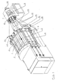
- a sample warping machine shown in Fig. 1 has a warping drum 1 as a winding body on the circumference of axially parachute conveyor belts 2 are arranged, which moves in the direction of an arrow 3 can be.
- the transport belts 3 form a transport surface arrangement.
- Parallel to the axis of the warping drum 1 are partial rods 4, 5, 6 arranged depending on their function also known as cross or cutting bars can be.
- Partial bars On the invisible opposite lying side of the warping drum 1 can more Partial bars may be arranged.
- a rotary gate 7 has a rotor 8, the one Carries a plurality of coils 9 and by a motor 10 is driven.
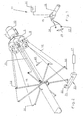
- the thread guide 11 have eyelets 13 through which the threads 12 are guided are. These eyelets 13 are at the front end Lever 14 arranged (Fig. 2 and 3), with the help of a Actuator 15 rotatable relative to a radial arm 16 is.
- the motor 15 is controlled by a control device 17 controlled so that the eyelet 13 in its position Direction of a double arrow 18 can change.
- the arms 16 are driven by the rotor 7 via a shaft 19, i.e. the thread guides 11 rotate synchronously the rotor 7.
- a thread thickness measuring device 20 is in the movement path the threads 12 arranged.
- the thread thickness measuring device has a measuring field 21 through which the thread 12 a circular path is led. He shadows you Sensor 22 depending on its thickness.
- the Thread thickness measuring device 20 thus determines each Thread 12 once per revolution (direction 23) the thickness and reports the thickness to the control device 17.
- Sorting fingers 24, 25, 26 are on the partial bars 4, 5, 6 arranged at the end that the rotary gate 7th is facing.
- the sorting fingers 24 - 26 serve to Thread so that they are either radially outside of the partial rods 4, 5, 6 or radially within the partial rods 4, 5, 6 come to rest, each based on the Warping drum 1.
- Using the sorting fingers 24, 25, 26 it is possible to form crosses. Crosses are needed usually at the beginning and end of a chain to one hand to separate the threads and on the other hand the To be able to cut threads.
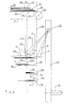
- Fig. 1 there are three partial bars shown. However, more partial bars can also be used be present, for example four, as shown in FIG. 4 is shown.
- Fig. 4 now shows a schematic side view of the Warping machine.
- the same elements as in Fig. 1 are with provided with the same reference numerals.
- four sub-bars, 4a, 4b, 5a, 5b which form of crosses at the beginning and end of the chain.
- Each sub-bar 4a, 4b or 5a, 5b is with a sorting finger 24a, 24b or 25a, 25b provided, as shown for the sorting finger 24a is pivotable in the direction of a double arrow 27 is.
- the transport belts 2 are guided around deflection rollers 28. There is already a winding on the transport belt 2 29 formed, i.e. you already have a variety of threads with an appropriate number of turns the warping drum 1 led around.
- the winding 29 in one by one Arrow 30 shown warping direction moved by the Transport belts 2 are driven. This movement can be done during winding, preferably with a constant speed. But it can also take place when a turn group has been completed and a new group of turns is started should.
- winding 29 is conical Front 31 has. Is shown in dashed lines a boundary 33 between the winding 29 and a winding group 32, which has just been completed.
- a turn group consists of a number of turns of the thread or threads that together the desired Length of the sample chain to be generated.
- the winding group 32 is conical on one side by the End face 31 and on the other side limited by the broken line 33.
- the front threads move (in the warping direction 30 seen) from a lower position 34 into one upper position 35 when the winding group is completed and the back threads move from one lower position 36 to an upper position 37 they are guided by the thread guides 11, more precisely from the eyelet 13 on the arm 14.
- the movement of the threads 12a, 12b during winding is replaced by a corresponding one Swiveling movement of the lever 14 caused by the motor 15 can be controlled.
- the two sub-staff groups are each with two partial bars 4a, 4b and 5a, 5b are provided. If threads lying next to each other are numbered, then Threads G with an even order number above of sub-bar 4a, while all other threads be wound directly into the winding 29. At the other Sub-bar 4b are the threads U with an odd order number filed above the sub-bar 4b and all other threads wound in the winding 29. With the two it is similar to other sub-bars 5a, i.e.
- the lever 14 is also pivoted further, than this for making a winding group is required.
- the Lever 14 pivoted into a position c, that is from a Area out that for winding the winding group is required.
- the eye 13 thus leaves a helical Railway with which they have so far been around Warping drum 1 has been led around.
- arm 14 is moved to a position d moved outside the helix to the rotary gate 7, around the thread 12d to the right of the sorting fingers 25a, 25b past, of course on the sorting finger 25a only threads with even serial number and on the sorting finger 25b only threads with an odd order number to be led past.
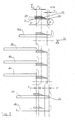
- FIG. 5 again shows a schematic Side view of the warping machine. Same parts as in Fig. 4 are given the same reference numerals.
- cutting bars 6a, 6b are now also shown.
- the cutting position is by scissors 38 shown on which the threads are cut, if the warping drum 1 has been completely wrapped.
- Cutting rod 6a become the first threads of a group of turns guided below 'the cutting rod 6a.
- At the Cutting rod 6b become the last threads of a group of turns guided above the cutting bar.
- the conical end face 31 of the winding 29 can be located at different positions between two extreme positions, one of which is shown as k 1 / k 2 and the other as k / s. In some cases there is a distance x 1 between the lower position 36 of the rear threads and the position k / s and in other cases there is a distance x 1 'between these two positions. Such a large difference in distance would practically no longer be manageable with normal sorting fingers. If, however, the threads are guided through the levers 14 each outside an area which is defined by the conical end face 31, these different distances no longer constitute a problem.
- the end position 37 of the rear threads can of course also differ from the other position k 1 / k 2 . It can be x 2 or x 2 '. These differences could not be handled by normal sorting fingers. The use of the new thread guide makes this problem practically disappear.
- At least the position c of the lever 14 in Fig. 4 can be an end position that the motor 15 can control. This simplifies control. The motor 15 becomes simple to reach this position c, in an end position hazards.
Landscapes
- Engineering & Computer Science (AREA)
- Textile Engineering (AREA)
- Warping, Beaming, Or Leasing (AREA)
Abstract
Description
- Fig. 1
- eine schematische Gesamtansicht einer Musterkettenschärmaschine mit Drehgatter,
- Fig. 2
- Fadenführer und Drehgatter der Schärmaschine nach Fig.1,
- Fig. 3
- eine Ausführungsform eines Fadenführers,
- Fig. 4
- eine schematische Darstellung zur Erläuterung der Fadenführung und
- Fig. 5
- eine weitere schematische Darstellung mit mehr Teilstäben.
Claims (15)
- Verfahren zum Erzeugen einer Musterkette, bei dem mindestens ein Faden zur Bildung einer Windungsgruppe mit einer vorbestimmten Anzahl von Windungen um den Umfang einer Schärtrommel geführt und auf einer Transportflächenanordnung an der Schärtrommel abgelegt wird, dadurch gekennzeichnet, daß der Faden bei mindestens einer Windung mindestens einmal in Richtung auf ein erstes Ende der Schärtrommel aus der Windungsgruppe heraus bewegt wird und bei mindestens einer Windung mindestens einmal in Richtung auf ein zweites Ende der Schärtrommel aus der Windungsgruppe heraus bewegt wird.
- Verfahren nach Anspruch 2, dadurch gekennzeichnet, daß der Faden mit einer umlaufenden Fadenführereinrichtung geführt wird, deren Abstand zum ersten Ende der Schärtrommel veränderbar ist.
- Verfahren nach Anspruch 1 oder 2, dadurch gekennzeichnet, daß der Faden bei der Bewegung in Richtung auf das erste Ende der Schärtrommel vor einer Fangeinrichtung an einem Teilstab und bei der Bewegung in Richtung auf das zweite Ende hinter einer Fangeinrichtung an einem Teilstab geführt wird und man die Fangeinrichtungen im Zusammenhang mit den Bewegungen des Fadens betätigt.
- Verfahren nach einem der Ansprüche 1 bis 3, dadurch gekennzeichnet, daß der Faden bei mindestens einer Bewegung aus der Windungsgruppe heraus in eine feste Endposition bewegt wird.
- Verfahren nach Anspruch 4, dadurch gekennzeichnet, daß die Endposition der maximalen Auslenkung der Fadenführereinrichtung entspricht.
- Verfahren nach einem der Ansprüche 1 bis 5, dadurch gekennzeichnet, daß mehrere Fäden gleichzeitig um den Umfang der Schärtrommel geführt werden, wobei die Fäden nebeneinander abgelegt werden.
- Verfahren nach Anspruch 6, dadurch gekennzeichnet, daß die mehreren Fäden axial auf der gleichen Position abgelegt werden, wenn sie in die erste und/oder die zweite Richtung aus der Windungsgruppe heraus bewegt werden.
- Verfahren nach einem der Ansprüche 1 bis 7, dadurch gekennzeichnet, daß die Bewegung in die erste und/oder die zweite Richtung in Abhängigkeit von einer Geschwindigkeit gestartet wird, mit der der Faden um die Schärtrommel herum geführt wird.
- Verfahren nach einem der Ansprüche 1 bis 8, dadurch gekennzeichnet, daß bei jeder Windung jeder Faden mindestens einmal in Dickenrichtung gemessen wird und der Fadenführer in Abhängigkeit von der gemessenen Dicke gesteuert wird.
- Verfahren nach einem der Ansprüche 1 bis 9, dadurch gekennzeichnet, daß Windungsgruppen mit unterschiedlicher Breite erzeugt werden und die Transportflächenanordnung mit konstanter Geschwindigkeit in die zweite Richtung bewegt wird, wobei jede Windungsgruppe in einem Raum zwischen zwei Extrempositionen gehalten wird.
- Verfahren nach Anspruch 10, dadurch gekennzeichnet, daß man unterschiedliche Platzbedarfe von verschiedenen Windungsgruppen durch Wahl einer axialen Verlagerungsbewegung der Fäden berücksichtigt.
- Musterkettenschärmaschine mit einer Schärtrommel, die eine axial bewegbare Transportflächenanordnung aufweist, und einer Fadenführeranordnung mit mindestens einer Fadenführereinrichtung, die auf einer Schraubenlinie um den Umfang der Schärtrommel herum bewegbar ist, dadurch gekennzeichnet, daß die Fadenführereinrichtung (13) über den Anfang und das Ende der Schraubenlinie hinaus bewegbar ist.
- Maschine nach Anspruch 12, dadurch gekennzeichnet, daß mehrere Fadenführereinrichtungen (13) vorgesehen sind, die mehrere Fäden (12) gleichzeitig um die Schärtrommel (1) herum führen, wobei die Fadenführereinrichtungen (13) im Bereich der Schraubenlinie so angeordnet sind, daß sie die Fäden (12) nebeneinander ablegen, und in einem Bereich außerhalb der Schraubenlinie so angeordnet sind, daß sie die Fäden (12) auf der gleichen axialen Position der Schärtrommel (1) ablegen.
- Maschine nach Anspruch 12 oder 13, dadurch gekennzeichnet, daß die Bewegungsgeschwindigkeit und/oder der Bewegungszeitpunkt der Fadenführereinrichtung (13) aus der Schraubenlinie heraus von der Geschwindigkeit abhängt, mit der die Fadenführereinrichtung (13) um die Schärtrommel (1) herum bewegt wird.
- Maschine nach einem der Ansprüche 12 bis 14, dadurch gekennzeichnet, daß eine Fadendickenmeßeinrichtung (20) vorgesehen ist, die bei jedem Umlauf mindestens einmal die Dicke jedes um die Schärtrommel (1) geführten Fadens (12) ermittelt, wobei eine Steuereinrichtung (17) vorgesehen ist, die die axiale Komponente der Bewegung der Fadenführereinrichtung (13) in Abhängigkeit von der ermittelten Dicke steuert.
Applications Claiming Priority (2)
| Application Number | Priority Date | Filing Date | Title |
|---|---|---|---|
| DE2003123382 DE10323382B4 (de) | 2003-05-23 | 2003-05-23 | Verfahren zum Erzeugen einer Musterkette und Musterkettenschärmaschine |
| DE10323382 | 2003-05-23 |
Publications (3)
| Publication Number | Publication Date |
|---|---|
| EP1479804A2 true EP1479804A2 (de) | 2004-11-24 |
| EP1479804A3 EP1479804A3 (de) | 2005-04-27 |
| EP1479804B1 EP1479804B1 (de) | 2009-02-18 |
Family
ID=33039297
Family Applications (1)
| Application Number | Title | Priority Date | Filing Date |
|---|---|---|---|
| EP20040007005 Expired - Lifetime EP1479804B1 (de) | 2003-05-23 | 2004-03-24 | Verfahren zum Erzeugen einer Musterkette und Musterkettenschärmaschine |
Country Status (4)
| Country | Link |
|---|---|
| EP (1) | EP1479804B1 (de) |
| JP (1) | JP4176045B2 (de) |
| DE (2) | DE10323382B4 (de) |
| ES (1) | ES2319985T3 (de) |
Cited By (1)
| Publication number | Priority date | Publication date | Assignee | Title |
|---|---|---|---|---|
| EP2302116A1 (de) | 2009-09-29 | 2011-03-30 | Karl Mayer Textilmaschinenfabrik GmbH | Verfahren zum Erzeugen einer Musterkette und Musterkettenschärmaschine |
Families Citing this family (3)
| Publication number | Priority date | Publication date | Assignee | Title |
|---|---|---|---|---|
| DE502006001696D1 (de) * | 2006-07-26 | 2008-11-13 | Mayer Textilmaschf | Musterkettenschärmaschine und Verfahren zum Erzeugen eines Musterkettbaumes |
| EP1882761B1 (de) * | 2006-07-26 | 2009-03-18 | KARL MAYER TEXTILMASCHINENFABRIK GmbH | Musterkettenschärmaschine |
| DE502006005365D1 (de) * | 2006-12-09 | 2009-12-24 | Mayer Textilmaschf | Musterkettenschärmaschine und Verfahren zum Erzeugen einer Musterkette |
Family Cites Families (7)
| Publication number | Priority date | Publication date | Assignee | Title |
|---|---|---|---|---|
| DE9422068U1 (de) * | 1993-11-09 | 1997-10-16 | Suzuki Warper Ltd., Kiryu, Gunma | Musterschärmaschine |
| DE4411203A1 (de) * | 1994-03-31 | 1995-10-05 | Temco Textilmaschkomponent | Vorrichtung zur Messung des Verwindungsgleichmaßes, der Drehungen/m, Fadendicken, der Produktionsgeschwindigkeit sowie der Lauflängen von Fäden |
| DE19845244C1 (de) * | 1998-10-01 | 1999-09-23 | Mayer Textilmaschf | Musterketten-Schärmaschine |
| DE10057356B4 (de) * | 2000-11-18 | 2005-11-24 | Karl Mayer Textilmaschinenfabrik Gmbh | Verfahren zum Erzeugen einer Musterkette und Musterketten-Schärmaschine |
| DE10057354B4 (de) * | 2000-11-18 | 2006-08-17 | Karl Mayer Textilmaschinenfabrik Gmbh | Verfahren zum Erzeugen einer Musterkette und Musterketten-Schärmaschine |
| DE10061490C1 (de) * | 2000-12-09 | 2001-11-29 | Mayer Textilmaschf | Verfahren zum Erzeugen einer Musterkette und Musterketten-Schärmaschine |
| DE10157254B4 (de) * | 2001-11-22 | 2005-12-15 | Karl Mayer Textilmaschinenfabrik Gmbh | Kurzketten-Schärmaschine und Verfahren zum Erzeugen einer Kurzkette |
-
2003
- 2003-05-23 DE DE2003123382 patent/DE10323382B4/de not_active Expired - Fee Related
-
2004
- 2004-03-24 ES ES04007005T patent/ES2319985T3/es not_active Expired - Lifetime
- 2004-03-24 EP EP20040007005 patent/EP1479804B1/de not_active Expired - Lifetime
- 2004-03-24 DE DE200450008997 patent/DE502004008997D1/de not_active Expired - Lifetime
- 2004-05-24 JP JP2004153040A patent/JP4176045B2/ja not_active Expired - Lifetime
Cited By (2)
| Publication number | Priority date | Publication date | Assignee | Title |
|---|---|---|---|---|
| EP2302116A1 (de) | 2009-09-29 | 2011-03-30 | Karl Mayer Textilmaschinenfabrik GmbH | Verfahren zum Erzeugen einer Musterkette und Musterkettenschärmaschine |
| CN102031613B (zh) * | 2009-09-29 | 2013-01-02 | 卡尔迈尔纺织机械制造有限公司 | 用于制造提花链的方法以及提花链整经机 |
Also Published As
| Publication number | Publication date |
|---|---|
| ES2319985T3 (es) | 2009-05-18 |
| JP2004346480A (ja) | 2004-12-09 |
| DE502004008997D1 (de) | 2009-04-02 |
| EP1479804A3 (de) | 2005-04-27 |
| DE10323382A1 (de) | 2004-12-30 |
| DE10323382B4 (de) | 2006-09-14 |
| JP4176045B2 (ja) | 2008-11-05 |
| EP1479804B1 (de) | 2009-02-18 |
Similar Documents
| Publication | Publication Date | Title |
|---|---|---|
| DE1927769A1 (de) | Vorrichtung zum Herstellen von Streifen durch Schlitzen einer Papierbahn | |
| CH662368A5 (de) | Vorrichtung zur herstellung von kurzketten, insbesondere fuer gewebemuster in der buntweberei. | |
| DE69504789T2 (de) | Schussfadenliefervorrichtung mit vorrichtung zum trennen von wendungen für schnelllaufende luftdüsenwebmaschinen | |
| EP1809798B1 (de) | Verfahren und vorrichtung zum wickeln eines aus einer mehrzahl von parallelen fäden bestehenden bandes auf eine um eine drehachse rotierende trommel | |
| EP1479804B1 (de) | Verfahren zum Erzeugen einer Musterkette und Musterkettenschärmaschine | |
| DE10323383B4 (de) | Verfahren zum Erzeugen einer Musterkette und Musterkettenschärmaschine | |
| EP1930489B1 (de) | Musterkettenschärmaschine und Verfahren zum Erzeugen einer Musterkette | |
| DE19535087A1 (de) | Rundstrickmaschine | |
| DE10302254B4 (de) | Verfahren zum Erzeugen einer Musterkette und Musterkettenschärmaschine | |
| EP2975176B1 (de) | Vorrichtung zum Herstellen von Wendelsieben | |
| DE10057354B4 (de) | Verfahren zum Erzeugen einer Musterkette und Musterketten-Schärmaschine | |
| DE10057356B4 (de) | Verfahren zum Erzeugen einer Musterkette und Musterketten-Schärmaschine | |
| DE19910833C1 (de) | Kurzketten-Schärmaschine | |
| DE10323352B4 (de) | Verfahren zum Erzeugen einer Musterkette und Musterkettenschärmaschine | |
| EP1918434B1 (de) | Musterkettenschärmaschine | |
| EP1479805B1 (de) | Musterkettenschärmaschine | |
| EP2239356B1 (de) | Musterkettenschärmaschine und Verfahren zum Betreiben einer Musterkettenschärmaschine | |
| EP2540884B1 (de) | Musterkettenschärmaschine | |
| DE2051030A1 (de) | Verfahren und Vorrichtung zur Her stellung von Ketten | |
| EP0929706B1 (de) | Verfahren und vorrichtung zum umeinanderschlingen von wenigstens zwei laufenden fäden | |
| EP2154277B1 (de) | Kettbaum | |
| EP1918435B1 (de) | Musterkettenschärmaschine | |
| EP2239357B1 (de) | Musterkettenschärmaschine | |
| DE1176068B (de) | Verfahren zum Fuellen der Schuetzen bei einer Webmaschine, insbesondere bei einer Web-maschine mit Einbringung der Schussfaeden durch sich kolonnenartig in Wanderfaechern hinterein-anderbewegende Schuetzen, und Webmaschine zur Ausfuehrung des Verfahrens | |
| DE102006023496A1 (de) | Musterschärverfahren und Musterschärer mit gleichzeitigem, ordnungsgemässem Aufspulen mehrerer Garne |
Legal Events
| Date | Code | Title | Description |
|---|---|---|---|
| PUAI | Public reference made under article 153(3) epc to a published international application that has entered the european phase |
Free format text: ORIGINAL CODE: 0009012 |
|
| AK | Designated contracting states |
Kind code of ref document: A2 Designated state(s): AT BE BG CH CY CZ DE DK EE ES FI FR GB GR HU IE IT LI LU MC NL PL PT RO SE SI SK TR |
|
| AX | Request for extension of the european patent |
Extension state: AL LT LV MK |
|
| PUAL | Search report despatched |
Free format text: ORIGINAL CODE: 0009013 |
|
| AK | Designated contracting states |
Kind code of ref document: A3 Designated state(s): AT BE BG CH CY CZ DE DK EE ES FI FR GB GR HU IE IT LI LU MC NL PL PT RO SE SI SK TR |
|
| AX | Request for extension of the european patent |
Extension state: AL LT LV MK |
|
| 17P | Request for examination filed |
Effective date: 20050330 |
|
| AKX | Designation fees paid |
Designated state(s): CH DE ES IT LI |
|
| GRAP | Despatch of communication of intention to grant a patent |
Free format text: ORIGINAL CODE: EPIDOSNIGR1 |
|
| GRAS | Grant fee paid |
Free format text: ORIGINAL CODE: EPIDOSNIGR3 |
|
| GRAA | (expected) grant |
Free format text: ORIGINAL CODE: 0009210 |
|
| AK | Designated contracting states |
Kind code of ref document: B1 Designated state(s): CH DE ES IT LI |
|
| REG | Reference to a national code |
Ref country code: CH Ref legal event code: EP Ref country code: CH Ref legal event code: NV Representative=s name: BOVARD AG PATENTANWAELTE |
|
| REF | Corresponds to: |
Ref document number: 502004008997 Country of ref document: DE Date of ref document: 20090402 Kind code of ref document: P |
|
| PGFP | Annual fee paid to national office [announced via postgrant information from national office to epo] |
Ref country code: ES Payment date: 20090325 Year of fee payment: 6 |
|
| REG | Reference to a national code |
Ref country code: ES Ref legal event code: FG2A Ref document number: 2319985 Country of ref document: ES Kind code of ref document: T3 |
|
| PGFP | Annual fee paid to national office [announced via postgrant information from national office to epo] |
Ref country code: CH Payment date: 20090325 Year of fee payment: 6 |
|
| PLBE | No opposition filed within time limit |
Free format text: ORIGINAL CODE: 0009261 |
|
| STAA | Information on the status of an ep patent application or granted ep patent |
Free format text: STATUS: NO OPPOSITION FILED WITHIN TIME LIMIT |
|
| 26N | No opposition filed |
Effective date: 20091119 |
|
| REG | Reference to a national code |
Ref country code: CH Ref legal event code: PL |
|
| PG25 | Lapsed in a contracting state [announced via postgrant information from national office to epo] |
Ref country code: CH Free format text: LAPSE BECAUSE OF NON-PAYMENT OF DUE FEES Effective date: 20100331 Ref country code: LI Free format text: LAPSE BECAUSE OF NON-PAYMENT OF DUE FEES Effective date: 20100331 |
|
| REG | Reference to a national code |
Ref country code: ES Ref legal event code: FD2A Effective date: 20110415 |
|
| PG25 | Lapsed in a contracting state [announced via postgrant information from national office to epo] |
Ref country code: ES Free format text: LAPSE BECAUSE OF NON-PAYMENT OF DUE FEES Effective date: 20110404 |
|
| PG25 | Lapsed in a contracting state [announced via postgrant information from national office to epo] |
Ref country code: ES Free format text: LAPSE BECAUSE OF NON-PAYMENT OF DUE FEES Effective date: 20100325 |
|
| REG | Reference to a national code |
Ref country code: DE Ref legal event code: R082 Ref document number: 502004008997 Country of ref document: DE Ref country code: DE Ref legal event code: R082 Ref document number: 502004008997 Country of ref document: DE Representative=s name: KEIL & SCHAAFHAUSEN PATENT- UND RECHTSANWAELTE, DE |
|
| REG | Reference to a national code |
Ref country code: DE Ref legal event code: R082 Ref document number: 502004008997 Country of ref document: DE Ref country code: DE Ref legal event code: R081 Ref document number: 502004008997 Country of ref document: DE Owner name: KARL MAYER R&D GMBH, DE Free format text: FORMER OWNER: KARL MAYER TEXTILMASCHINENFABRIK GMBH, 63179 OBERTSHAUSEN, DE Ref country code: DE Ref legal event code: R081 Ref document number: 502004008997 Country of ref document: DE Owner name: KARL MAYER STOLL R&D GMBH, DE Free format text: FORMER OWNER: KARL MAYER TEXTILMASCHINENFABRIK GMBH, 63179 OBERTSHAUSEN, DE |
|
| PGFP | Annual fee paid to national office [announced via postgrant information from national office to epo] |
Ref country code: IT Payment date: 20230321 Year of fee payment: 20 Ref country code: DE Payment date: 20230328 Year of fee payment: 20 |
|
| P01 | Opt-out of the competence of the unified patent court (upc) registered |
Effective date: 20230704 |
|
| REG | Reference to a national code |
Ref country code: DE Ref legal event code: R071 Ref document number: 502004008997 Country of ref document: DE |