EP1477324A2 - Verfahren zum Einbinden eines Blattstapels in einen Einband, Bindevorrichtung zur Durchführung dieses Verfahrens sowie ein hierfür geeigneter Einband - Google Patents
Verfahren zum Einbinden eines Blattstapels in einen Einband, Bindevorrichtung zur Durchführung dieses Verfahrens sowie ein hierfür geeigneter Einband Download PDFInfo
- Publication number
- EP1477324A2 EP1477324A2 EP04009053A EP04009053A EP1477324A2 EP 1477324 A2 EP1477324 A2 EP 1477324A2 EP 04009053 A EP04009053 A EP 04009053A EP 04009053 A EP04009053 A EP 04009053A EP 1477324 A2 EP1477324 A2 EP 1477324A2
- Authority
- EP
- European Patent Office
- Prior art keywords
- cover
- stack
- sheet stack
- binding device
- binding
- Prior art date
- Legal status (The legal status is an assumption and is not a legal conclusion. Google has not performed a legal analysis and makes no representation as to the accuracy of the status listed.)
- Withdrawn
Links
Images


Classifications
-
- B—PERFORMING OPERATIONS; TRANSPORTING
- B42—BOOKBINDING; ALBUMS; FILES; SPECIAL PRINTED MATTER
- B42C—BOOKBINDING
- B42C9/00—Applying glue or adhesive peculiar to bookbinding
- B42C9/0056—Applying glue or adhesive peculiar to bookbinding applying tape or covers precoated with adhesive to a stack of sheets
-
- B—PERFORMING OPERATIONS; TRANSPORTING
- B42—BOOKBINDING; ALBUMS; FILES; SPECIAL PRINTED MATTER
- B42C—BOOKBINDING
- B42C11/00—Casing-in
- B42C11/04—Machines or equipment for casing-in or applying covers to books
Definitions
- the invention relates to a method for integrating a Stack of sheets in a cover that has a cover spine with an adhesive strip on the inside has, with in the cover Sheet stack is inserted so that its end face in The adhesive strips come into contact, after which the Sheet stack by means of a press device with fanning out the face of the stack of sheets pressed together and then in this state an adhesive connection between Cover spine and stack of sheets is produced.
- the invention further relates to a binding device to carry out this method, the binding device a pressing device for compressing the Sheet stack has.
- the invention relates a cover that is particularly suitable for the process is.
- bindings are for example from US 3,437,506, DE-PS-25 28 225, US 4,244,069, U 4,289,330 and EP 0 140 197 B1 known.
- Suitable binding devices for binding are DE-AS-22 56 259, US-RE. 28,758, US 3,973,778, US 4,129,471, US 4,141,100, DE 38 05 996 C2 and EP 0 581 394 B1.
- All binding devices are designed so that the combination of Sheet stack and cover in an upward open slot be used so that the outside of the cover spine is facing down.
- the back cover is on a bottom of the adjustment shaft Hotplate placed on and heated by this.
- the binding device has a pressing device which the combination compresses and in the upright position holds.
- the pressing device is usually designed so that of the side walls delimiting the adjustment shaft at least one slidable relative to the other is guided so that the width of the insertion shaft changed and the combination between the two Sidewalls can be kept pressed.
- the invention is therefore based on the object of a method for binding a stack of sheets in a cover to be designed so that a much stronger connection between the cover and the stack of sheets.
- a second Part of the job is to find a suitable one To provide device.
- a third part of the task has a suitable cover.
- the first part of the task is thereby according to the invention solved that the pressing device when pressing the A line print either directly on the sheet stack Stacks of sheets or exerts on the cover from the outside and thereby fanning the face of the stack of sheets is achieved.
- the pressing device when pressing the A line print either directly on the sheet stack Stacks of sheets or exerts on the cover from the outside and thereby fanning the face of the stack of sheets is achieved.
- a fanning out of Sheet stack by means of either the press directly on the sheet stack or on the combination line pressure exerted by the sheet stack and cover.
- the fanning can designed by setting the line pressure accordingly be that the width of the front of the Sheet stack becomes larger than the thickness of the sheet stack in the non-compressed area, i.e. in the area that - seen from the back of the cover - the line pressure removed lies. This creates particularly wide gaps between the front edges of the sheet stack and thus good penetration of the adhesive between the individual leaves.
- a particularly good spreading effect is achieved if the sheet stack at a distance of 0.5 to 2 cm from line pressure is applied to its face.
- the Line pressurization can be caused by, for example the above press bars belonging to the pressing device happen.
- a particularly firm connection with the help of the invention can be achieved in that the Cover spine and the face of the sheet stack at Production of the adhesive connection with an additionally applied Pressure force are pressed against each other. This will penetrate the plasticized Hot melt adhesive between the sheets of the sheet stack improved. You can also use this method Bindings are used in which the cover spine with an adhesive strip from a pressure sensitive Pressure sensitive adhesive is provided. That way, at the binders on the heater and the associated energy costs are waived.
- the compressive force is preferably exerted on the back of the cover applied. This can be flat, for example with the help of a pressure plate.
- the pressure force can also be applied progressively in a line be, for example by a along the cover spine movable pressure roller.
- an adhesive strip is used, the width of which at least 1.2 times the thickness of the sheet stack in corresponds to the uncompressed state, so that also the outer Leaves of the sheet stack after it is fanned out by the Glue can be detected. The same applies to the Width of the spine.
- the second part of the task is thereby solved that the pressing device is designed such that they line print when compressing the stack of sheets either directly onto the sheet stack or from on the outside of the cover.
- the pressing device relative to each other and has pressing bars that can be moved relative to one another, which are attached to holding elements such that they are a also protruding position relative to the holding elements when pressing the stack of sheets.
- a holding element fixture and the other holding element relative to one is movably guided, as well as an embodiment in question, with the two holding elements relative are movably guided to each other.
- the pressure bars can be attached to the holding elements in a resilient manner, as long as it is ensured that they protrude their protruding Maintain position and thus a line print is exerted on the sheet stack.
- the pressure strips are rigidly attached to the holding elements.
- the pressure bars are advantageously arranged that when the combination is used as intended from cover and stack of sheets in the area of the cover spine adjacent half of the sheet stack run preferably at a distance of 0.5 to 2 cm from the back cover. This way one becomes special good fanning out achieved.
- the binding device is a pressing device for the Press the cover spine against the sheet stack at the same Has compression.
- the pressure device can one against the outside of the back cover have press ram that can be applied as Press roll that can be rolled off the cover or as the cover spine formed press plate can be.
- the binding device must Heating device for plasticizing the adhesive strip, for example in the form of a heating plate. This can be placed flat on the back of the cover and by this can be moved away again when the combination from cover and stack of sheets as intended in the Binding device is set.
- the binding device has an adjustment shaft and the pressure bars in the area of the first half the insertion shaft, seen from its insertion opening, is arranged.
- a pressing device and / or a heating device are present, they should be on one of the holding elements in the area of the adjustment opening be arranged.
- the third part of the task, which relates to the cover, is solved according to the invention in that the adhesive strip the cover has a reinforcing insert, preferably in the form of a textile strip, such as of a gauze strip.
- This training also contributes to you better hold of the connection between adhesive strips and sheet stack at.
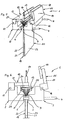
- the binding device 1 shown in the figures has two in cross-section L-shaped holding elements 2, 3 on arranged parallel to each other and at the same height are.
- the left-hand holding element 2 has two transverse to its longitudinal extent horizontally Guide rods 4, 5 on the right-hand holding element 3 penetrate so that this holding element 3 on the Guide rods 4, 5 relative to the left-hand holding element 2 and displaceable transversely to its longitudinal extent is led. In this way, the free distance be changed between the holding elements 2, 3.
- the two holding elements 2, 3 and the guide rods 4, 5 limit the upper end of a not shown here Adjustment shaft, which is down to the Holding elements 2, 3 connects.
- Adjustment shaft which is down to the Holding elements 2, 3 connects.
- On other parts of the binding device 1, especially the device frame with Control devices etc. is here for reasons of clarity been waived.
- a heating element 10 pivotally mounted about an axis 11, which is parallel runs to the longitudinal axis of the holding element 2.
- the heating element 10 has a carrier plate 12, at its free end a heating plate 13 perpendicular to the plane of the support plate 12 is slidably attached.
- the heating plate 13 has one Terminal block 14 for connection to an electrical Power source.
- the heating plate 13 extends almost the entire length of the holding element 2 between the two Guide rods 4, 5.
- the heating plate 13 can on a The temperature at which a cover is usually used used hot melt adhesive plasticized can be.
- a pressure element 15 pivotally mounted about an axis 16, the Axis 16 is parallel to axis 11 and thus parallel extends to the longitudinal axes of the holding elements 2, 3.
- the Pressing element 15 has a carrier plate 17, on its free end of a press plate 18 is attached.
- a combination 19 of cover 20 and sheet stack 21 used in the vertical position is a combination 19 of cover 20 and sheet stack 21 used in the vertical position.
- the combination 19 can with its underside for example on a support plate be deposed.
- the cover 20 has two cover covers 22, 23, which cover the sheet stack 21 areal.
- the cover covers 22, 23 are on the top by a Cover spine 24 connected to the cover 22, 23 in one piece and connected to them via folds is.
- the back cover 24 is considerably wider than the thickness of the sheet stack 21, the conditions here for the purpose better representation of this configuration exaggerated are shown.
- an adhesive strip 25 made of a hot melt adhesive applied. It adheres firmly to the back cover 24 and is reinforced with a gauze strip that is in the Adhesive strip 25 is embedded.
- the sheet stack 21 lies with its top face 26 on the free Side of the adhesive strip 25 or has only a small Distance to it.
- Binding device 1 and the combination 19 from Cover 20 and sheet stack 21 are as follows. First, the combination 19 - as in FIGS. 1 and 2 - in the binding device 1 from above set so that it is the one shown in these figures Takes position.
- the cover 20 is in the area of the back cover 24 preformed so that the distance of the Cover cover 22, 23 of the adhesive strip 25 initially remains the same, but then only stronger and then less tapered until the cover 22, 23 at the level of the pressure bars 8, 9 in contact with the sheet stack 21 come.
- the combination 19 with the cover 22 on the left side press bar 8 while the right side Press bar 9 still a considerable distance from this Combination 19 has. Both the heating element 10 and the pressing element 15 are pivoted up so that the Support plates 12, 17 are almost vertical.
- the diversification is so limited that the Front edges of the two outer leaves of the Sheet stack 21 still below the adhesive strip 25 are located.
- the fanning out again has the consequence that the sheets of the sheet stack 21 in the region of the end face 26 have a distance from each other.
- FIGs 5 and 6 is the plasticizing step of the adhesive strip 25 shown. Opposite the Position according to Figures 3 and 4, the heating element 10 pivoted so that the heating plate 13 on the Outside of the back cover 24 flat to the system comes. This creates such heat on the adhesive strips 25 transferred that he the plasticizing temperature reached and thereby as well as due to the Pressure of the heating plate 13 in the spaces between the sheets of the sheet stack 21 penetrate. That remains the line pressure exerted on the pressure bars 8, 9 received.
- the heating element 10 is again in its starting position pivoted up and instead the pressing element 15 in the direction pivoted down to the cover spine 24 and brought to the plant on the outside.
- About the press plate 18 pressure is applied vertically downwards, so that the distance of the back cover 24 to the pressure bars 8, 9 decreased. This leads to further penetration of the adhesive strip 25 in the spaces between sheets of a sheet stack 21. Panning of heating element 10 and pressing element 15 can be done by hand via appropriate levers, but also by electric motor.
Landscapes
- Engineering & Computer Science (AREA)
- Mechanical Engineering (AREA)
- Folding Of Thin Sheet-Like Materials, Special Discharging Devices, And Others (AREA)
Abstract
Description
- Figur 1
- die erfindungsgemäße Bindevorrichtung mit eingesetzter Kombination aus Einband und Blattstapel vor dem Bindevorgang in perspektivischer Ansicht;
- Figur 2
- die Bindevorrichtung in der Stellung gemäß Figur 1 in stirnseitiger Ansicht;
- Figur 3
- die Bindevorrichtung gemäß den Figuren 1 und 2 bei zusammengedrückter Kombination aus Einband und Blattstapel in perspektivischer Ansicht;
- Figur 4
- die Bindevorrichtung in der Stellung gemäß Figur 3 in stirnseitiger Ansicht;
- Figur 5
- die Bindevorrichtung gemäß den Figuren 1 bis 4 in der Stellung mit auf den Einbandrücken aufgesetzter Heizplatte in perspektivischer Ansicht;
- Figur 6
- die Bindevorrichtung in der Stellung gemäß Figur 5 in stirnseitiger Ansicht;
- Figur 7
- die Bindevorrichtung gemäß den Figuren 1 bis 6 mit der Preßplatte in Anlage an den Einbandrükken in perspektivischer Ansicht und
- Figur 8
- die Bindevorrichtung in der Stellung gemäß Figur 7 in stirnseitiger Ansicht.
Claims (31)
- Verfahren zum Einbinden eines Blattstapels (21) in einen Einband (20), der einen Einbandrücken (24) mit einem auf dessen Innenseite vorhandenen Klebstoffstreifen (25) aufweist, wobei der Blattstapel (21) in den Einband (20) so eingelegt wird, daß dessen Stirnseite in Kontakt mit dem Klebstoffstreifen (25) kommt, wonach der Blattstapel (21) mittels einer Preßeinrichtung (2, 3, 8, 9) unter Auffächerung der Stirnseite (26) des Blattstapels (21) zusammengepreßt und danach in diesem Zustand eine Klebeverbindung zwischen Einbandrücken (24) und Blattstapel (21) hergestellt wird, dadurch gekennzeichnet, daß die Preßeinrichtung (2, 3, 8, 9) beim Zusammenpressen des Blattstapels (21) einen Liniendruck entweder direkt auf den Blattstapel (21) oder von außen auf den Einband (20) ausübt.
- Verfahren nach Anspruch 1, dadurch gekennzeichnet, daß der Blattstapel (21) durch das Zusammenpressen derart aufgefächert wird, daß die Breite der Stirnseite (26) des Blattstapels (21) größer wird als die Dicke des Blattstapels (21) im nicht verpreßten Bereich.
- Verfahren nach Anspruch 1 oder 2, dadurch gekennzeichnet, daß der Blattstapel (21) in einem Abstand von 0,5 bis 2 cm von seiner Stirnseite (26) mit Liniendruck beaufschlagt wird.
- Verfahren nach einem der Ansprüche 1 bis 3, dadurch gekennzeichnet, daß der Blattstapel (21) durch zu der Preßeinrichtung gehörende, vorstehende Preßleisten (8, 9) mit Liniendruck beaufschlagt wird.
- Verfahren nach einem der Ansprüche 1 bis 4, dadurch gekennzeichnet, daß der Einbandrücken (24) und die Stirnseite (26) des Blattstapels (21) bei Herstellung der Klebeverbindung mit einer zusätzlich aufgebrachten Druckkraft gegeneinander gedrückt werden.
- Verfahren nach Anspruch 5, dadurch gekennzeichnet, daß die Druckkraft von außen auf den Einbandrücken (24) aufgebracht wird.
- Verfahren nach Anspruch 5 oder 6, dadurch gekennzeichnet, daß die Druckkraft flächig aufgebracht wird.
- Verfahren nach Anspruch 5 oder 6, dadurch gekennzeichnet, daß die Druckkraft linienförmig fortschreitend aufgebracht wird.
- Verfahren nach einem der Ansprüche 1 bis 8, dadurch gekennzeichnet, daß das Zusammendrücken des Blattstapels (21) in dessen horizontaler oder vertikaler Stellung mit seitlich verlaufendem Einbandrücken (24), einer vertikalen Stellung mit obenseitigem Einbandrücken (24) oder in einer Stellung erfolgt, die zwischen diesen Stellungen liegt.
- Verfahren nach einem der Ansprüche 1 bis 9, dadurch gekennzeichnet, daß ein Einbandrücken (24) mit einem Klebestreifen (25) aus Schmelzklebstoff verwendet wird und dieser Klebstoffstreifen bei zusammengepreßtem Blattstapel (21) auf eine Plastifizierungstemperatur erhitzt wird.
- Verfahren nach einem der Ansprüche 1 bis 9, dadurch gekennzeichnet, daß ein Einbandrücken mit einem Klebstoffstreifen aus druckempfindlichem Haftklebstoff verwendet wird und dieser Klebstoffstreifen bei zusammengepreßtem Blattstapel gegen diesen gepreßt wird.
- Verfahren nach einem der Ansprüche 1 bis 10, dadurch gekennzeichnet, daß ein Klebstoffstreifen (25) verwendet wird, dessen Breite wenigstens dem 1,2-fachen der Dicke des Blattstapels (21) in unverpreßtem Zustand entspricht.
- Bindevorrichtung (1) zum Einbinden eines Blattstapels (21) in einen Einband (20) mit einem Einbandrücken (24) und einem auf dessen Innenseite vorhandenen Klebstoffstreifens (25), wobei die Bindevorrichtung (1) eine Preßeinrichtung (2, 3, 8, 9) zum Zusammenpressen des Blattstapels (21) aufweist, dadurch gekennzeichnet, daß die Preßeinrichtung (2, 3, 8, 9) derart ausgebildet ist, daß sie beim Zusammenpressen des Blattstapels (21) ein Liniendruck entweder direkt auf den Blattstapel (21) oder von außen auf den Einband (20) ausübt.
- Bindevorrichtung nach Anspruch 13, dadurch gekennzeichnet, daß die Preßeinrichtung zwei relativ zueinander und gegeneinander bewegbare Preßleisten (8, 9) aufweist, die an Halteelementen (2, 3) derart angebracht sind, daß sie eine gegenüber den Halteelementen (2, 3) vorstehende Stellung auch beim Verpressen des Blattstapels (21) inne haben.
- Bindevorrichtung nach Anspruch 14, dadurch gekennzeichnet, daß die Preßleisten (8, 9) starr an den Halteelementen (2, 3) befestigt sind.
- Bindevorrichtung nach Anspruch 14 oder 15, dadurch gekennzeichnet, daß die Preßleisten derart angeordnet sind, daß sie bei bestimmungsgemäß eingebrachter Kombination (19) aus Einband (20) und Blattstapel (21) im Bereich der dem Einbandrücken (24) benachbarten Hälfte des Blattstapels (21) verlaufen.
- Bindevorrichtung nach Anspruch 16, dadurch gekennzeichnet, daß die Preßleisten (8, 9) in einem Abstand von 0,5 bis 2 cm vom Einbandrücken (24) verlaufen, wenn die Kombination (19) aus Einband (20) und Blattstapel (21) bestimmungsgemäß in die Bindevorrichtung (1) eingestellt ist.
- Bindevorrichtung nach einem der Ansprüche 13 bis 17, dadurch gekennzeichnet, daß die Bindevorrichtung (1) eine Andrückeinrichtung (15) für das Andrücken des Einbandrückens (24) an den Blattstapel (21) bei dessen Verpressung aufweist.
- Bindevorrichtung nach Anspruch 18, dadurch gekennzeichnet, daß die Andrückeinrichtung (15) ein gegen die Außenseite des Einbandrückens (24) anlegbaren Preßstempel (18) aufweist.
- Bindevorrichtung nach Anspruch 19, dadurch gekennzeichnet, daß der Preßstempel als über den Einbandrücken abrollbare Preßrolle ausgebildet ist.
- Bindevorrichtung nach Anspruch 19, dadurch gekennzeichnet, daß der Preßstempel als auf den Einbandrükken (24) flächig aufdrückbare Preßplatte (18) ausgebildet ist.
- Bindevorrichtung nach einem der Ansprüche 13 bis 21, dadurch gekennzeichnet, daß die Bindevorrichtung (1) eine Heizeinrichtung (10) zur Plastifizierung des Klebstoffstreifens (25) aufweist.
- Bindevorrichtung nach Anspruch 22, dadurch gekennzeichnet, daß die Heizeinrichtung (10) eine Heizplatte (13) aufweist.
- Bindevorrichtung nach Anspruch 23, dadurch gekennzeichnet, daß die Heizplatte (13) an den Einbandrükken (24) flächig anlegbar und von diesem wieder weg bewegbar ist, wenn die Kombination (19) aus Einband (20) und Blattstapel (21) bestimmungsgemäß in die Bindevorrichtung (1) eingestellt ist.
- Bindevorrichtung nach einem der Ansprüche 13 bis 24, dadurch gekennzeichnet, daß die Bindevorrichtung (1) einen Einstellschacht aufweist und die Preßleisten (8, 9) im Bereich der ersten Hälfte des Einstellschachtes, gesehen von dessen Einstellöffnung, angeordnet sind.
- Bindevorrichtung nach Anspruch 25, dadurch gekennzeichnet, daß die Einstellöffnung zur Seite, schräg nach oben oder nach oben hin offen ist.
- Bindevorrichtung nach einem der Ansprüche 18 bis 21 und Anspruch 25 oder 26, dadurch gekennzeichnet, daß die Andrückeinrichtung (15) an einem der Halteelemente (2, 3) im Bereich der Einstellöffnung beweglich gelagert ist.
- Bindevorrichtung nach einem der Ansprüche 22 bis 24 und Anspruch 25 oder 26, dadurch gekennzeichnet, daß die Heizeinrichtung (10) an einem der Halteelemente (2, 3) im Bereich der Einstellöffnung angeordnet ist.
- Einband (20) zum Einbinden eines Blattstapels (21), mit einem Einbandrücken (24), auf dessen Innenseite ein Klebstoffstreifen (25) angebracht ist, dadurch gekennzeichnet, daß der Klebstoffstreifen (25) eine Verstärkungseinlage aufweist.
- Einband nach Anspruch 29, dadurch gekennzeichnet, daß der Verstärkungsstreifen als Textilstreifen ausgebildet ist.
- Einband nach Anspruch 30, dadurch gekennzeichnet, daß der Textilstreifen ein Gazestreifen ist.
Applications Claiming Priority (2)
| Application Number | Priority Date | Filing Date | Title |
|---|---|---|---|
| DE10321419 | 2003-05-12 | ||
| DE10321419 | 2003-05-12 |
Publications (2)
| Publication Number | Publication Date |
|---|---|
| EP1477324A2 true EP1477324A2 (de) | 2004-11-17 |
| EP1477324A3 EP1477324A3 (de) | 2006-06-07 |
Family
ID=33016366
Family Applications (1)
| Application Number | Title | Priority Date | Filing Date |
|---|---|---|---|
| EP04009053A Withdrawn EP1477324A3 (de) | 2003-05-12 | 2004-04-16 | Verfahren zum Einbinden eines Blattstapels in einen Einband, Bindevorrichtung zur Durchführung dieses Verfahrens sowie ein hierfür geeigneter Einband |
Country Status (2)
| Country | Link |
|---|---|
| US (1) | US7326019B2 (de) |
| EP (1) | EP1477324A3 (de) |
Cited By (3)
| Publication number | Priority date | Publication date | Assignee | Title |
|---|---|---|---|---|
| EP1623841A2 (de) | 2004-08-03 | 2006-02-08 | Swedex GmbH & Co. KG | Verfahren zum Einbinden eines Blattstapels in einen Einband sowie Bindevorrichtung zur Durchführung dieses Verfahrens |
| EP1637343A1 (de) | 2004-09-21 | 2006-03-22 | Monolith GmbH Bürosysteme | Verfahren zum Einbinden eines Blattstapels in einen Einband und Bindevorrichtung zur Durchführung dieses Verfahrens |
| CN111671247A (zh) * | 2020-06-01 | 2020-09-18 | 江苏苏宁银行股份有限公司 | 一种资料放置装置 |
Families Citing this family (8)
| Publication number | Priority date | Publication date | Assignee | Title |
|---|---|---|---|---|
| US20060029487A1 (en) * | 2004-08-03 | 2006-02-09 | Bernd Loibl | Method for binding a sheet stack into a binder, and binding apparatus for carrying out that method |
| JP5145795B2 (ja) * | 2006-07-24 | 2013-02-20 | 新日鐵住金株式会社 | 耐摩耗性および延性に優れたパーライト系レールの製造方法 |
| US20090071866A1 (en) * | 2007-09-13 | 2009-03-19 | Cornelius Chow | Portable thermal document binding machine |
| JP2010069794A (ja) * | 2008-09-19 | 2010-04-02 | Noritsu Koki Co Ltd | 製本装置 |
| CN102501678B (zh) * | 2011-11-25 | 2014-12-24 | 平湖英厚机械有限公司 | 带断丝回收和自动清洗的喷胶机构及回收清洗方法 |
| KR101454231B1 (ko) * | 2012-10-04 | 2014-10-23 | 양 서문 | 압축식 앨범 제작장치 |
| CN107954248B (zh) * | 2017-09-12 | 2019-08-02 | 刘艺舟 | 一种快速试卷配页装订器 |
| CN108583050A (zh) * | 2018-03-21 | 2018-09-28 | 安徽芜湖新华印务有限责任公司 | 一种胶装机用可调压边装置 |
Citations (6)
| Publication number | Priority date | Publication date | Assignee | Title |
|---|---|---|---|---|
| FR673507A (fr) * | 1928-06-13 | 1930-01-16 | Fortuna Werke Spezialmaschinen | Dispositif pour enduire de colle le dos des brochures et mettre la couverture en place sur la brochure |
| DE955226C (de) * | 1952-09-24 | 1957-01-03 | Willy Hesselmann | Vorrichtung fuer die fadenlose Bindung von Schriftstuecken und sonstigen Papierblaettern |
| DE1411004A1 (de) * | 1958-08-04 | 1968-10-03 | Willy Hesselmann | Vorrichtung zum Klebebinden von Papierstapeln aus losen Blaettern vornehmlich unterschiedlichen Formates |
| US4009498A (en) * | 1972-06-22 | 1977-03-01 | General Binding Corporation | Bookbinding system |
| US4141100A (en) * | 1976-09-27 | 1979-02-27 | Domroe William E | Binding machine and cover for use therewith |
| US5314283A (en) * | 1989-06-20 | 1994-05-24 | Xerox Corporation | Apparatus for applying hard and soft covers to bound or unbound documents |
Family Cites Families (25)
| Publication number | Priority date | Publication date | Assignee | Title |
|---|---|---|---|---|
| CH333541A (de) | 1954-05-15 | 1958-10-31 | Prakma Maschinenfabrik Gmbh | Verfahren zur Herstellung von Broschüren |
| DE1077181B (de) | 1957-11-23 | 1960-03-10 | Prakma Maschinenfabrik G M B H | Einpressvorrichtung an Maschinen zum Herstellen von Broschueren |
| US3437506A (en) * | 1964-12-28 | 1969-04-08 | Joanna Western Mills Co | Bookbinding tape |
| US3973738A (en) * | 1969-10-15 | 1976-08-10 | The Globe Tool And Engineering Company | Armature winding and leading connecting machine |
| US3930082A (en) * | 1971-06-10 | 1975-12-30 | Dick Co Ab | Bookbinding tape |
| USRE28758E (en) * | 1971-06-23 | 1976-04-06 | Method and apparatus used for book binding | |
| BE792361A (fr) | 1971-12-06 | 1973-06-06 | Xerox Corp | Procede et appareil de reliure d'une pile de |
| US3973787A (en) | 1973-06-19 | 1976-08-10 | General Binding Corporation | Bookbinding system |
| CA1046551A (en) | 1974-07-01 | 1979-01-16 | General Binding Corporation | Heat activatable binding cover with pressure sensitive adhesive |
| US4129471A (en) * | 1975-06-05 | 1978-12-12 | Rome Industries, Inc. | Bookbinding technique |
| US4244069A (en) * | 1979-05-29 | 1981-01-13 | Xerox Corporation | Method and apparatus for binding sheets |
| US4289330A (en) * | 1979-10-10 | 1981-09-15 | General Binding Corporation | Bookbinding system |
| US4303724A (en) * | 1980-09-04 | 1981-12-01 | The Kendall Co. | Adhesive tapes containing texturized yarns |
| DE8331187U1 (de) | 1983-10-29 | 1984-04-19 | Swedex Vertriebs-GmbH für technische und elektrotechnische Geräte, 4040 Neuss | Einband für Papierblätter |
| GB2184981B (en) | 1985-09-25 | 1990-07-11 | Easibind Ltd | A book and method of producing same |
| SE457244B (sv) | 1987-03-02 | 1988-12-12 | Bind O Matic Ab | Foerfarande och anordning foer att binda loesa ark i en bindemedelsfoersedd paerm |
| US4923351A (en) * | 1987-06-10 | 1990-05-08 | Maruni Kasei Kabushiki Kaisha | Bookbinding and its products |
| BE1002552A4 (nl) * | 1988-10-07 | 1991-03-19 | Lolli Carla P | Universeel inbindelement voor het inbinden van losse dokumenten in een map. |
| SE500756C2 (sv) | 1989-09-15 | 1994-08-29 | Jan Tholerus | Sätt och maskin för tillverkning av häften |
| US5221112A (en) * | 1991-12-11 | 1993-06-22 | Holmberg Albert E | Method and apparatus for binding books |
| US5871323A (en) * | 1995-05-31 | 1999-02-16 | National Starch And Chemical Investment Holding Corporation | Bookbinding |
| US6142721A (en) * | 1998-01-30 | 2000-11-07 | Marsh; Jeffrey D. | Apparatus for and method of binding a book |
| US6652210B1 (en) | 2000-02-25 | 2003-11-25 | Yeaple Corporation | Individual book-binding system and method |
| GB0005333D0 (en) * | 2000-03-07 | 2000-04-26 | Watkiss Automation Ltd | Methods of and apparatus for producing booklets |
| FI119287B (fi) * | 2002-01-29 | 2008-09-30 | Maping Ky L Huotari | Menetelmä ja laite kuumaliimaukseen |
-
2004
- 2004-04-16 EP EP04009053A patent/EP1477324A3/de not_active Withdrawn
- 2004-05-11 US US10/842,629 patent/US7326019B2/en not_active Expired - Fee Related
Patent Citations (6)
| Publication number | Priority date | Publication date | Assignee | Title |
|---|---|---|---|---|
| FR673507A (fr) * | 1928-06-13 | 1930-01-16 | Fortuna Werke Spezialmaschinen | Dispositif pour enduire de colle le dos des brochures et mettre la couverture en place sur la brochure |
| DE955226C (de) * | 1952-09-24 | 1957-01-03 | Willy Hesselmann | Vorrichtung fuer die fadenlose Bindung von Schriftstuecken und sonstigen Papierblaettern |
| DE1411004A1 (de) * | 1958-08-04 | 1968-10-03 | Willy Hesselmann | Vorrichtung zum Klebebinden von Papierstapeln aus losen Blaettern vornehmlich unterschiedlichen Formates |
| US4009498A (en) * | 1972-06-22 | 1977-03-01 | General Binding Corporation | Bookbinding system |
| US4141100A (en) * | 1976-09-27 | 1979-02-27 | Domroe William E | Binding machine and cover for use therewith |
| US5314283A (en) * | 1989-06-20 | 1994-05-24 | Xerox Corporation | Apparatus for applying hard and soft covers to bound or unbound documents |
Cited By (7)
| Publication number | Priority date | Publication date | Assignee | Title |
|---|---|---|---|---|
| EP1623841A2 (de) | 2004-08-03 | 2006-02-08 | Swedex GmbH & Co. KG | Verfahren zum Einbinden eines Blattstapels in einen Einband sowie Bindevorrichtung zur Durchführung dieses Verfahrens |
| DE102004037806A1 (de) * | 2004-08-03 | 2006-03-16 | Swedex Gmbh & Co. Kg | Verfahren zum Einbinden eines Blattstapels in einen Einband sowie Bindevorrichtung zur Durchführung dieses Verfahrens |
| EP1623841A3 (de) * | 2004-08-03 | 2006-11-29 | Swedex GmbH & Co. KG | Verfahren zum Einbinden eines Blattstapels in einen Einband sowie Bindevorrichtung zur Durchführung dieses Verfahrens |
| DE102004037806B4 (de) * | 2004-08-03 | 2015-01-15 | Swedex Gmbh & Co. Kg | Verfahren zum Einbinden eines Blattstapels in einen Einband sowie Bindevorrichtung zur Durchführung dieses Verfahrens |
| EP1637343A1 (de) | 2004-09-21 | 2006-03-22 | Monolith GmbH Bürosysteme | Verfahren zum Einbinden eines Blattstapels in einen Einband und Bindevorrichtung zur Durchführung dieses Verfahrens |
| DE102004046039A1 (de) * | 2004-09-21 | 2006-04-06 | Swedex Gmbh & Co. Kg | Verfahren zum Einbinden eines Blattstapels in einen Einband, Bindevorrichtung zur Durchführung dieses Verfahrens |
| CN111671247A (zh) * | 2020-06-01 | 2020-09-18 | 江苏苏宁银行股份有限公司 | 一种资料放置装置 |
Also Published As
| Publication number | Publication date |
|---|---|
| US7326019B2 (en) | 2008-02-05 |
| US20050008459A1 (en) | 2005-01-13 |
| EP1477324A3 (de) | 2006-06-07 |
Similar Documents
| Publication | Publication Date | Title |
|---|---|---|
| DE2256259A1 (de) | Verfahren und v8rrichtung zum binden eines blattstapels | |
| CH651505A5 (de) | Verfahren zum herstellen eines einbandes fuer ein buch, ein heft oder eine broschuere und vorrichtung zur durchfuehrung des verfahrens. | |
| DE1479841A1 (de) | Verfahren zum Heissschneiden und -kleben von uebereinandergelegten Lagen aus thermoplastischem Material und Vorrichtung zur Durchfuehrung des Verfahrens | |
| EP0201530B1 (de) | Verfahren zum heissverformen einer kunstharz-schichtpresstoffplatte, sowie vorrichtung zur durchführung dieses verfahrens | |
| EP1477324A2 (de) | Verfahren zum Einbinden eines Blattstapels in einen Einband, Bindevorrichtung zur Durchführung dieses Verfahrens sowie ein hierfür geeigneter Einband | |
| DE3707675C2 (de) | ||
| EP0176844A2 (de) | Verfahren und Vorrichtung zur Herstellung eines Einbandes oder dergleichen sowie Einband | |
| WO2007131572A1 (de) | Vertikale schlauchbeutelmaschine mit zwei linearmotoren | |
| DE19945279C1 (de) | Vorrichtung sowie Verfahren zur Herstellung von Fußbodenpaneelen und verfahrensgemäß hergestellte Paneele | |
| DE3916774C2 (de) | ||
| DE3010642C2 (de) | ||
| DE2320196C3 (de) | Verfahren zur Herstellung eines gewölbten, langgestreckten Sportgerätes, z.B. Ski oder Bogen, sowie zur Durchfuhrung des Verfahrens verwendete Form | |
| DE2254281A1 (de) | Vorrichtung zum stanzen von formlingen oder materialbahnen | |
| WO1988006082A1 (en) | Process and equipment for the manufacture of chip-board and board of similar materials | |
| DE60320638T2 (de) | Verfahren zum heisskleben | |
| EP1637343A1 (de) | Verfahren zum Einbinden eines Blattstapels in einen Einband und Bindevorrichtung zur Durchführung dieses Verfahrens | |
| DE102004037806B4 (de) | Verfahren zum Einbinden eines Blattstapels in einen Einband sowie Bindevorrichtung zur Durchführung dieses Verfahrens | |
| EP0392047A1 (de) | Verfahren und Vorrichtung zum Heissverformen einer Kunstharz-Schichtpressstoffplatte | |
| AT506369B1 (de) | Spannschiene für eine membrane einer membranpresse | |
| WO2009067821A1 (de) | Wanderdeckel | |
| DE1801195A1 (de) | Verfahren und Vorrichtung zur Verbindung laenglicher Metallteile mit Metallblech | |
| DE10141391C1 (de) | Verfahren zur Herstellung von dauernd weichbiegsamen Holz sowie Einrichtung hierzu | |
| EP1377395B1 (de) | Biegemaschine, insbesondere gesenk- oder abkantpresse, mit einem verstellbaren unterwerkzeug | |
| DE2427434A1 (de) | Vorrichtung zur herstellung von nuten in folien, insbesondere aus polypropylen | |
| DE3051053C2 (en) | Application of cover to book or brochure |
Legal Events
| Date | Code | Title | Description |
|---|---|---|---|
| PUAI | Public reference made under article 153(3) epc to a published international application that has entered the european phase |
Free format text: ORIGINAL CODE: 0009012 |
|
| AK | Designated contracting states |
Kind code of ref document: A2 Designated state(s): AT BE BG CH CY CZ DE DK EE ES FI FR GB GR HU IE IT LI LU MC NL PL PT RO SE SI SK TR |
|
| AX | Request for extension of the european patent |
Extension state: AL HR LT LV MK |
|
| PUAL | Search report despatched |
Free format text: ORIGINAL CODE: 0009013 |
|
| AK | Designated contracting states |
Kind code of ref document: A3 Designated state(s): AT BE BG CH CY CZ DE DK EE ES FI FR GB GR HU IE IT LI LU MC NL PL PT RO SE SI SK TR |
|
| AX | Request for extension of the european patent |
Extension state: AL HR LT LV MK |
|
| 17P | Request for examination filed |
Effective date: 20060603 |
|
| AKX | Designation fees paid |
Designated state(s): AT CH DE FR GB LI NL |
|
| RAP1 | Party data changed (applicant data changed or rights of an application transferred) |
Owner name: MONOLITH GMBH BUEROSYSTEME |
|
| 17Q | First examination report despatched |
Effective date: 20100324 |
|
| STAA | Information on the status of an ep patent application or granted ep patent |
Free format text: STATUS: THE APPLICATION IS DEEMED TO BE WITHDRAWN |
|
| 18D | Application deemed to be withdrawn |
Effective date: 20100804 |