EP1475868A2 - laser à cavité externe - Google Patents
laser à cavité externe Download PDFInfo
- Publication number
- EP1475868A2 EP1475868A2 EP04012777A EP04012777A EP1475868A2 EP 1475868 A2 EP1475868 A2 EP 1475868A2 EP 04012777 A EP04012777 A EP 04012777A EP 04012777 A EP04012777 A EP 04012777A EP 1475868 A2 EP1475868 A2 EP 1475868A2
- Authority
- EP
- European Patent Office
- Prior art keywords
- light
- wavelength
- external cavity
- wavelength selection
- emitting element
- Prior art date
- Legal status (The legal status is an assumption and is not a legal conclusion. Google has not performed a legal analysis and makes no representation as to the accuracy of the status listed.)
- Withdrawn
Links
Images

Classifications
-
- H—ELECTRICITY
- H01—ELECTRIC ELEMENTS
- H01S—DEVICES USING THE PROCESS OF LIGHT AMPLIFICATION BY STIMULATED EMISSION OF RADIATION [LASER] TO AMPLIFY OR GENERATE LIGHT; DEVICES USING STIMULATED EMISSION OF ELECTROMAGNETIC RADIATION IN WAVE RANGES OTHER THAN OPTICAL
- H01S3/00—Lasers, i.e. devices using stimulated emission of electromagnetic radiation in the infrared, visible or ultraviolet wave range
- H01S3/05—Construction or shape of optical resonators; Accommodation of active medium therein; Shape of active medium
- H01S3/08—Construction or shape of optical resonators or components thereof
- H01S3/08018—Mode suppression
- H01S3/08022—Longitudinal modes
- H01S3/08031—Single-mode emission
- H01S3/08036—Single-mode emission using intracavity dispersive, polarising or birefringent elements
-
- H—ELECTRICITY
- H01—ELECTRIC ELEMENTS
- H01S—DEVICES USING THE PROCESS OF LIGHT AMPLIFICATION BY STIMULATED EMISSION OF RADIATION [LASER] TO AMPLIFY OR GENERATE LIGHT; DEVICES USING STIMULATED EMISSION OF ELECTROMAGNETIC RADIATION IN WAVE RANGES OTHER THAN OPTICAL
- H01S5/00—Semiconductor lasers
- H01S5/10—Construction or shape of the optical resonator, e.g. extended or external cavity, coupled cavities, bent-guide, varying width, thickness or composition of the active region
- H01S5/14—External cavity lasers
- H01S5/141—External cavity lasers using a wavelength selective device, e.g. a grating or etalon
-
- H—ELECTRICITY
- H01—ELECTRIC ELEMENTS
- H01S—DEVICES USING THE PROCESS OF LIGHT AMPLIFICATION BY STIMULATED EMISSION OF RADIATION [LASER] TO AMPLIFY OR GENERATE LIGHT; DEVICES USING STIMULATED EMISSION OF ELECTROMAGNETIC RADIATION IN WAVE RANGES OTHER THAN OPTICAL
- H01S3/00—Lasers, i.e. devices using stimulated emission of electromagnetic radiation in the infrared, visible or ultraviolet wave range
- H01S3/05—Construction or shape of optical resonators; Accommodation of active medium therein; Shape of active medium
- H01S3/08—Construction or shape of optical resonators or components thereof
- H01S3/08004—Construction or shape of optical resonators or components thereof incorporating a dispersive element, e.g. a prism for wavelength selection
- H01S3/08009—Construction or shape of optical resonators or components thereof incorporating a dispersive element, e.g. a prism for wavelength selection using a diffraction grating
-
- H—ELECTRICITY
- H01—ELECTRIC ELEMENTS
- H01S—DEVICES USING THE PROCESS OF LIGHT AMPLIFICATION BY STIMULATED EMISSION OF RADIATION [LASER] TO AMPLIFY OR GENERATE LIGHT; DEVICES USING STIMULATED EMISSION OF ELECTROMAGNETIC RADIATION IN WAVE RANGES OTHER THAN OPTICAL
- H01S3/00—Lasers, i.e. devices using stimulated emission of electromagnetic radiation in the infrared, visible or ultraviolet wave range
- H01S3/05—Construction or shape of optical resonators; Accommodation of active medium therein; Shape of active medium
- H01S3/08—Construction or shape of optical resonators or components thereof
- H01S3/08059—Constructional details of the reflector, e.g. shape
-
- H—ELECTRICITY
- H01—ELECTRIC ELEMENTS
- H01S—DEVICES USING THE PROCESS OF LIGHT AMPLIFICATION BY STIMULATED EMISSION OF RADIATION [LASER] TO AMPLIFY OR GENERATE LIGHT; DEVICES USING STIMULATED EMISSION OF ELECTROMAGNETIC RADIATION IN WAVE RANGES OTHER THAN OPTICAL
- H01S3/00—Lasers, i.e. devices using stimulated emission of electromagnetic radiation in the infrared, visible or ultraviolet wave range
- H01S3/05—Construction or shape of optical resonators; Accommodation of active medium therein; Shape of active medium
- H01S3/08—Construction or shape of optical resonators or components thereof
- H01S3/081—Construction or shape of optical resonators or components thereof comprising three or more reflectors
- H01S3/0811—Construction or shape of optical resonators or components thereof comprising three or more reflectors incorporating a dispersive element, e.g. a prism for wavelength selection
- H01S3/0812—Construction or shape of optical resonators or components thereof comprising three or more reflectors incorporating a dispersive element, e.g. a prism for wavelength selection using a diffraction grating
-
- H—ELECTRICITY
- H01—ELECTRIC ELEMENTS
- H01S—DEVICES USING THE PROCESS OF LIGHT AMPLIFICATION BY STIMULATED EMISSION OF RADIATION [LASER] TO AMPLIFY OR GENERATE LIGHT; DEVICES USING STIMULATED EMISSION OF ELECTROMAGNETIC RADIATION IN WAVE RANGES OTHER THAN OPTICAL
- H01S3/00—Lasers, i.e. devices using stimulated emission of electromagnetic radiation in the infrared, visible or ultraviolet wave range
- H01S3/05—Construction or shape of optical resonators; Accommodation of active medium therein; Shape of active medium
- H01S3/08—Construction or shape of optical resonators or components thereof
- H01S3/081—Construction or shape of optical resonators or components thereof comprising three or more reflectors
- H01S3/082—Construction or shape of optical resonators or components thereof comprising three or more reflectors defining a plurality of resonators, e.g. for mode selection or suppression
- H01S3/0823—Construction or shape of optical resonators or components thereof comprising three or more reflectors defining a plurality of resonators, e.g. for mode selection or suppression incorporating a dispersive element, e.g. a prism for wavelength selection
- H01S3/0826—Construction or shape of optical resonators or components thereof comprising three or more reflectors defining a plurality of resonators, e.g. for mode selection or suppression incorporating a dispersive element, e.g. a prism for wavelength selection using a diffraction grating
-
- H—ELECTRICITY
- H01—ELECTRIC ELEMENTS
- H01S—DEVICES USING THE PROCESS OF LIGHT AMPLIFICATION BY STIMULATED EMISSION OF RADIATION [LASER] TO AMPLIFY OR GENERATE LIGHT; DEVICES USING STIMULATED EMISSION OF ELECTROMAGNETIC RADIATION IN WAVE RANGES OTHER THAN OPTICAL
- H01S3/00—Lasers, i.e. devices using stimulated emission of electromagnetic radiation in the infrared, visible or ultraviolet wave range
- H01S3/10—Controlling the intensity, frequency, phase, polarisation or direction of the emitted radiation, e.g. switching, gating, modulating or demodulating
- H01S3/101—Lasers provided with means to change the location from which, or the direction in which, laser radiation is emitted
-
- H—ELECTRICITY
- H01—ELECTRIC ELEMENTS
- H01S—DEVICES USING THE PROCESS OF LIGHT AMPLIFICATION BY STIMULATED EMISSION OF RADIATION [LASER] TO AMPLIFY OR GENERATE LIGHT; DEVICES USING STIMULATED EMISSION OF ELECTROMAGNETIC RADIATION IN WAVE RANGES OTHER THAN OPTICAL
- H01S5/00—Semiconductor lasers
- H01S5/10—Construction or shape of the optical resonator, e.g. extended or external cavity, coupled cavities, bent-guide, varying width, thickness or composition of the active region
- H01S5/14—External cavity lasers
- H01S5/141—External cavity lasers using a wavelength selective device, e.g. a grating or etalon
- H01S5/143—Littman-Metcalf configuration, e.g. laser - grating - mirror
Definitions
- the present invention relates to an external cavity laser type light source having a wavelength selection element.
- an external cavity type semiconductor laser light source will be described as an example of a conventional external cavity type light source.
- a semiconductor laser will be referred to as LD in this specification hereinafter.
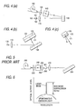
- Fig. 5 is a view showing an example of the arrangement of the conventional external cavity type LD light source.
- Fig. 6 is a graph showing a spectrum of output light of the external cavity type LD light source shown in Fig. 5.
- reference numeral 200 designates an LD
- reference numerals 201 and 202 designate end surfaces of the LD.
- an antireflection coating is provided on one end surface 201 of the external cavity type LD light source so as to prevent the occurrence of Fabry-Perot resonance on both end surfaces of the LD.
- a lens 210 After light is emitted from the end surface 201 on which the antireflection coating is provided, it is made to be parallel light by a lens 210 and then incident upon a diffraction grating 220 which is a wavelength selection element.
- a band-pass filter may be used as the wavelength selection element.
- the diffraction grating 220 After the wavelength of light is selected by the diffraction grating 220, the direction of light is changed by an angle of 180°. Then, light is condensed by the lens 210 and returned to the LD 200.
- an external cavity or resonator is composed of the end surface 202 of the LD 200 and the diffraction grating 220, and laser beam oscillation can be conducted by the resonator.
- a single wavelength selected by the diffraction grating 220 is ruling in the wavelength components of the output light.
- the wavelength components of the output light contain spontaneous emission light, the wavelength band of which is wide, which is directly emitted from the LD 200 onto the lens 230.
- output light contains laser beam, the wavelength of which has been selected by the wavelength selection element, and spontaneous emission light which has been directly emitted from the light emitting element. Therefore, when the characteristic of an optical filter or the like is measured by combining the external cavity type LD light source with a power meter, it is impossible to conduct measurement accurately. Especially, in the case of measurement conducted on a notch type filter, the above problem becomes remarkable.
- a ratio of an intensity of power of the laser beam of a single wavelength to an intensity of power of spontaneous emission light of a wide wavelength band is referred to as a side mode suppression ratio, which is approximately 40 dB in the conventional example described before.
- An object of the present invention is to provide an external cavity laser type light source, the wavelength purity of output light of which is very high, wherein an unnecessary spontaneous emission light component except for a selected wavelength component is cut off from the output light.
- the invention provides an external cavity laser type light source comprising: a light emitting element; a wavelength selection element for selecting a wavelength of light emitted from the light emitting element and for returning light to the light emitting element; and an optical branch element arranged between the light emitting element and the wavelength selection element, wherein selected light sent from the wavelength selection element is branched by the optical branch element, and one branched component is taken out as output light.
- the optical branch element is arranged between the light emitting element and the wavelength selection element, and light selected by the wavelength selection element is branched into two beams of light by the optical branch element. Then, one of the branched beams of light is taken out as output light. Due to the foregoing; an unnecessary spontaneous emission light component, the wavelength of which is different from the selected wavelength, can be cut off from the output light, so that the output light of highly pure wavelength can be obtained.
- examples of the light emitting element are a semiconductor laser element, a solid state laser element, a liquid laser element and a gas laser element.
- An example of the optical branch element is an unpolarized light beam splitter.
- examples of the wavelength selection element are a filter type wavelength selection element and a diffraction grating type wavelength selection element.
- an external cavity laser type light source comprising: a light emitting element; a diffraction grating for selecting a wavelength of light emitted from the light emitting element and for returning light to the light emitting element; and a mirror for reflecting light, wavelength of which has been selected by the diffraction grating, so that a direction of light is changed by an angle of 180° and light is made to be incident upon the diffraction grating again, the mirror being a multiple-surface reflecting mirror having at least two reflecting surfaces, angles of which are different from each other.
- the mirror for reflecting light, the wavelength of which has been selected by the diffraction grating, so that the direction of light can be changed by an angle of 180° and the light can be made to be incident upon the diffraction grating again. Therefore, a portion of light, the wavelength of which has been selected in the diffraction grating, is returned to the light emitting element. Since the mirror is a multiple-surface reflecting mirror having at least two reflecting surfaces, the angles of which are different from each other, a portion of light, the wavelength of which has been selected in the diffraction grating, proceeds in a direction different from that of the optical axis of the light emitting element.
- Fig. 1 is an arrangement view showing a first embodiment of the external cavity laser type light source to which the present invention is applied.
- the external cavity laser type light source of this embodiment includes: a light emitting element 1; a wavelength selection element 3 for selecting a wavelength of light emitted from the light emitting element 1; and an optical branch element 2 for branching selected light 4, which has been sent from the wavelength selection element 3, into output light 4A and return light 4B.
- a portion of the selected light 4 incident upon the optical branch element 2 is transmitted through the optical branch element 2 and returned to the light emitting element 4 as the return light 4B.
- an external cavity or resonator is composed of the wavelength selection element 3 and the end surface 1b of the light emitting element 2, and laser oscillation is conducted by this external resonator.
- the other portion of light, which has not been transmitted through the optical branch element 2, is reflected on the optical branch element 2, so that the direction of light is changed by an angle of 90°. This light is outputted outside as the output light 4A.
- Angle adjustment and cavity length adjustment of the wavelength selection element 3 are conducted by a rotating mechanism and a slide stage not shown in the drawings. Thus, the wavelength can be varied.
- the light emitting element 1 is an LD
- the optical branch element 2 is an unpolarized light beam splitter
- the wavelength selection element 3 is a diffraction grating.
- Fig. 2 is an arrangement view showing an external cavity type LD light source which is an example of the external cavity type light source.
- Fig. 3 is a graph showing a spectrum of output light which is outputted from the external cavity type LD light source shown in Fig. 2.
- this external cavity type LD light source includes: an LD 100 which is used as a light emitting element, a lens 110, an unpolarized light beam splitter 120 which is used as an optical branch element, a diffraction grating 130 which is used as a wavelength selection element, an optical isolator 140, a lens 150, and an optical fiber 160.
- an antireflection coating On an end surface 101 of the LD 100, there is provided an antireflection coating in the same manner as that of the conventional case.
- the transmittance of the unpolarized light beam splitter 120 is 80% (the reflectance is 20%). Therefore, 80% of a quantity of light incident upon the unpolarized light beam splitter 120 is incident upon the diffraction grating 130.
- Light incident upon the diffraction grating 130 is subjected to wavelength selection. After that, the direction of light is changed by an angle of 180°. Then, light is incident again upon the unpolarized light beam splitter 120. Then, 80% of a quantity of light incident upon the unpolarized light beam splitter 120 is transmitted through the unpolarized light beam splitter 120, and 20% thereof is reflected on the unpolarized light beam splitter 120 and proceeds.
- an external cavity or resonator is composed of the diffraction grating 120 and the end surface 102 of the LD 100, and laser oscillation is conducted by this external resonator.
- the spontaneous emission light component generated in the LD 100 is subjected to wavelength selection in the diffraction grating 130. Therefore, as shown in Fig. 3, a component of the wavelength except for the selected wavelength is very small, and its side mode suppression ratio exceeds 60 dB.
- the diffraction grating 130 After light is subjected to wavelength selection by the diffraction grating 130, it may be once sent to the transverse direction and then totally reflected on a mirror so that the thus reflected light is incident upon the diffraction grating 130 again. In this case, light is twice subjected to wavelength selection by the diffraction grating 130. Due to this, the wavelength selectivity can be further enhanced.
- the wavelength selection element 3 is not limited to the above diffraction grating 130.
- light emitted from the end surface 101 of the LD 100 passes through the unpolarized light beam splitter 120 and is incident upon the band-pass filter.
- the band-pass filter When light is incident upon the band-pass filter, it is subjected to wavelength selection in the process of passing through the band-pass filter, so that only light of a specific wavelength can be transmitted through the band-pass filter.
- Light which has been transmitted through the band-pass filter is reflected on the mirror, so that the direction of light is changed by an angle of 180°. Then light is transmitted again through the band-pass filter and incident upon the unpolarized light beam splitter 120.
- Light incident upon the unpolarized beam splitter 120 is branched into two beams of light in the same manner as that described before.
- One of the beams is taken outside as output light by the optical fiber 160, and the other beam is returned to the LD 100.
- the optical branch element 2 is arranged between the light emitting element 1 and the wavelength selection element 3, and selected light sent from the wavelength selection element 3 is branched by the optical branch element 2, and one branched component is taken out as output light. Therefore, an unnecessary spontaneous emission light component, the wavelength of which is different from the selected wavelength, can be cut off from the output light, so that the output light of highly pure wavelength can be obtained.
- the wavelength selection element 3 is rotated by an arbitrary angle with a rotating mechanism or the like, it is possible to select an arbitrary wavelength in accordance with the rotation angle.
- the wavelength selection element 3 is moved with a slide stage or the like by a predetermined distance in the direction of the optical axis of the light emitting element 1, it is possible to select an arbitrary wavelength in accordance with the distance of movement.
- Fig. 4 (a) is a plan view showing a second embodiment of the external cavity type LD light source to which the present invention is applied
- Fig. 4 (b) is a side view showing the same
- Fig. 4 (c) is a side view of a mirror in the second embodiment.
- the external cavity type LD light source of this embodiment includes: an LD 100, a lens 110, a diffraction grating 130, an optical isolator 140, a lens 150, an optical fiber 160, and a mirror 170.
- like reference characters are used to designate like parts in the first embodiment, and the description thereof is omitted here.
- the mirror 170 is a multiple-surface reflecting mirror having a plurality of reflecting surfaces, the angles of which are different from each other, that is, the reflecting mirror 170 is provided with a first reflecting surface 171 and a second reflecting surface 172.
- the first reflecting surface 171 On the first reflecting surface 171, selected light sent from the diffraction grating 130 is reflected and the direction of light is changed by an angle of 180°. The thus reflected light is incident upon the diffraction grating 130 again and returned to the LD 100 as returning light.
- the second reflecting surface 172 reflects light sent from the diffraction grating 130 in such a manner that the angle is shifted in the direction of the grooves of the diffraction grating 130.
- Light incident again upon the diffraction grating 130 is reflected, so that it proceeds in a direction different from that of the optical axis of the LD 100.
- light passes through the optical isolator 140 and is condensed by the lens 150.
- light is taken outside as output light by the optical fiber 160.
- the mirror 170 is provided with a plurality of reflecting angles, and light returning from the diffraction grating 130 is separated. Therefore, it is unnecessary to provide an optical branch element between the LD 100 and the diffraction grating 130.
- the mirror 170 may be composed of a single reflecting surface of a partial reflecting film, and light which has been transmitted through the mirror 170 may be used as output light.
- the beam profile becomes elliptical in this case. Therefore, it is difficult to effectively combine the transmitted light with the optical fiber.
- the mirror 170 is a multiple-surface reflecting mirror having at least two reflecting surfaces, the angles of which are different from each other, a portion of light, the wavelength of which has been selected in the diffraction grating 130, proceeds in a direction different from that of the optical axis of the LD 100.
- the present invention is not limited to the external cavity type LD light source of this embodiment.
- the light emitting element is not limited to a semiconductor laser element, but it is possible to use a solid state laser element, a liquid laser element and a gas laser element.
- the optical branch element is arranged between the light emitting element and the wavelength selection element, and selected light sent from the wavelength selection element is branched by the optical branch element, and one branched component is taken out as output light.
- an unnecessary spontaneous emission light component the wavelength of which is different from the selected wavelength, can be removed from the output light, so that the output light of highly pure wavelength can be obtained.
- the mirror for reflecting light, the wavelength of which has been selected by the diffraction grating, so that the direction of light can be changed by an angle of 180° and light can be made to be incident upon the diffraction grating again. Therefore, a portion of light, the wavelength of which has been selected in the diffraction grating, is returned to the light emitting element. Since the mirror is a multiple-surface reflecting mirror having at least two reflecting surfaces, the angles of which are different from each other, a portion of light, the wavelength of which has been selected in the diffraction grating, proceeds in a direction different from that of the optical axis of the light emitting element.
- the output light Since light, the wavelength of which has been selected in the diffraction grating, is branched into two beams of light by the mirror, one of the beams of light can be taken out as output light. That is, the output light, the wavelength purity of which is very high, from which an unnecessary spontaneous emission light component except for the selected wavelength is cut off, can be obtained.
Landscapes
- Physics & Mathematics (AREA)
- Electromagnetism (AREA)
- Optics & Photonics (AREA)
- Condensed Matter Physics & Semiconductors (AREA)
- General Physics & Mathematics (AREA)
- Engineering & Computer Science (AREA)
- Plasma & Fusion (AREA)
- Semiconductor Lasers (AREA)
- Lasers (AREA)
Applications Claiming Priority (3)
| Application Number | Priority Date | Filing Date | Title |
|---|---|---|---|
| JP29098797 | 1997-10-23 | ||
| JP29098797A JP3654401B2 (ja) | 1997-10-23 | 1997-10-23 | 外部共振器型光源 |
| EP98120118A EP0911924B1 (fr) | 1997-10-23 | 1998-10-23 | Source de lumière laser à cavité externe |
Related Parent Applications (1)
| Application Number | Title | Priority Date | Filing Date |
|---|---|---|---|
| EP98120118A Division EP0911924B1 (fr) | 1997-10-23 | 1998-10-23 | Source de lumière laser à cavité externe |
Publications (2)
| Publication Number | Publication Date |
|---|---|
| EP1475868A2 true EP1475868A2 (fr) | 2004-11-10 |
| EP1475868A3 EP1475868A3 (fr) | 2005-07-20 |
Family
ID=17763006
Family Applications (2)
| Application Number | Title | Priority Date | Filing Date |
|---|---|---|---|
| EP98120118A Expired - Lifetime EP0911924B1 (fr) | 1997-10-23 | 1998-10-23 | Source de lumière laser à cavité externe |
| EP04012777A Withdrawn EP1475868A3 (fr) | 1997-10-23 | 1998-10-23 | laser à cavité externe |
Family Applications Before (1)
| Application Number | Title | Priority Date | Filing Date |
|---|---|---|---|
| EP98120118A Expired - Lifetime EP0911924B1 (fr) | 1997-10-23 | 1998-10-23 | Source de lumière laser à cavité externe |
Country Status (5)
| Country | Link |
|---|---|
| US (1) | US6568105B1 (fr) |
| EP (2) | EP0911924B1 (fr) |
| JP (1) | JP3654401B2 (fr) |
| CA (1) | CA2251486C (fr) |
| DE (1) | DE69828560T2 (fr) |
Families Citing this family (8)
| Publication number | Priority date | Publication date | Assignee | Title |
|---|---|---|---|---|
| JP2001284716A (ja) * | 2000-03-30 | 2001-10-12 | Ando Electric Co Ltd | 外部共振器型レーザ光源 |
| JP2001284717A (ja) * | 2000-03-30 | 2001-10-12 | Ando Electric Co Ltd | 外部共振器型レーザ光源 |
| JP2001284715A (ja) * | 2000-03-30 | 2001-10-12 | Ando Electric Co Ltd | 外部共振器型レーザ光源 |
| US20050276303A1 (en) * | 2004-06-10 | 2005-12-15 | Rong Huang | External Cavity Laser |
| US7835417B2 (en) * | 2008-07-15 | 2010-11-16 | Octrolix Bv | Narrow spectrum light source |
| DE112013000969T5 (de) | 2012-02-14 | 2014-10-30 | TeraDiode, Inc. | Zweidimensionale Multistrahlstabilisierer- und -kombiniersysteme und -verfahren |
| ES2726812T3 (es) * | 2013-09-16 | 2019-10-09 | Humboldt Univ Zu Berlin | Unidad de láser de cavidad externa que incorpora filtro de interferencia de paso de banda de radiación infrarroja media |
| CN107069425B (zh) * | 2017-05-12 | 2019-08-20 | 中国科学院半导体研究所 | 多模激光器及其多模调节方法 |
Family Cites Families (29)
| Publication number | Priority date | Publication date | Assignee | Title |
|---|---|---|---|---|
| US3753148A (en) * | 1972-04-06 | 1973-08-14 | Nasa | Infrared tunable laser |
| US4589115A (en) * | 1983-09-09 | 1986-05-13 | Xerox Corporation | Wavelength tuning of quantum well heterostructure lasers using an external grating |
| JPS60110187A (ja) * | 1983-11-18 | 1985-06-15 | Matsushita Electric Ind Co Ltd | 光帰還型半導体レ−ザ装置 |
| JPS614187A (ja) | 1984-06-15 | 1986-01-10 | 松下電器産業株式会社 | マツト |
| JPS61124187A (ja) * | 1984-11-20 | 1986-06-11 | Fujitsu Ltd | 半導体レ−ザ発振波長制御装置 |
| US4822987A (en) | 1988-01-25 | 1989-04-18 | Westinghouse Electric Corp. | Method and apparatus for providing fuel rod identification to permit traceability during manufacture and use |
| JPH0216782A (ja) * | 1988-07-04 | 1990-01-19 | Toshiba Corp | 狭帯域レーザ装置 |
| DE3943470A1 (de) * | 1989-05-29 | 1990-12-13 | Rainer Thiessen | Gegenstands-naeherungs und troepfchendetektor |
| JPH0659665B2 (ja) | 1989-06-07 | 1994-08-10 | 帝人化成株式会社 | ポリカーボネート製容器 |
| US5150370A (en) * | 1989-06-14 | 1992-09-22 | Matsushita Electric Industrial Co., Ltd. | Narrow-band laser apparatus |
| DE69017852T2 (de) * | 1989-12-04 | 1995-08-10 | Canon Kk | Optisches Kopplergerät mit wellenlängeselektivem optischem Koppler. |
| JP2566331B2 (ja) * | 1990-03-29 | 1996-12-25 | アンリツ株式会社 | 可変波長光源装置 |
| JPH057768A (ja) | 1991-07-04 | 1993-01-19 | Ishikawajima Harima Heavy Ind Co Ltd | Co▲2▼の海洋処理方法 |
| JPH06509429A (ja) | 1991-07-26 | 1994-10-20 | アキュウェーブ コーポレーション | 光屈折性システムおよび方法 |
| DE69200586T2 (de) * | 1992-01-24 | 1995-05-24 | Hewlett Packard Gmbh | Verfahren und Apparat zum Abstimmen der Wellenlänge in einer optischen Vorrichtung und deren Anwendung in einem Laser. |
| JP3461848B2 (ja) * | 1992-03-23 | 2003-10-27 | 株式会社東芝 | 波長可変型レーザ装置 |
| JP3281414B2 (ja) | 1992-06-18 | 2002-05-13 | 株式会社アマダ | 鋸 刃 |
| US5386426A (en) * | 1992-09-10 | 1995-01-31 | Hughes Aircraft Company | Narrow bandwidth laser array system |
| JPH06140717A (ja) * | 1992-10-23 | 1994-05-20 | Ando Electric Co Ltd | 外部共振器型半導体レーザ光源 |
| US5392308A (en) * | 1993-01-07 | 1995-02-21 | Sdl, Inc. | Semiconductor laser with integral spatial mode filter |
| JPH06326382A (ja) * | 1993-05-14 | 1994-11-25 | Koshin Kogaku:Kk | 外部共振半導体レーザー |
| JPH0799359A (ja) * | 1993-09-27 | 1995-04-11 | Ando Electric Co Ltd | 外部共振器型周波数可変半導体レーザ光源 |
| US5452312A (en) * | 1993-10-18 | 1995-09-19 | Matsushita Electric Industrial Co., Ltd. | Short-wavelength laser light source and optical information processing aparatus |
| JPH07240558A (ja) * | 1994-02-28 | 1995-09-12 | Ando Electric Co Ltd | 波長可変半導体レーザ光源 |
| JP2603443B2 (ja) | 1994-06-27 | 1997-04-23 | 株式会社巴工芸社 | 回転式ファイル及びその製造方法 |
| JPH0832161A (ja) * | 1994-07-15 | 1996-02-02 | Fuji Photo Film Co Ltd | 半導体発光装置 |
| US5559816A (en) | 1994-10-26 | 1996-09-24 | Lambda Physik Gesellschaft Zur Herstellung Von Lasern Mbh | Narrow-band laser apparatus |
| US6101211A (en) * | 1995-04-03 | 2000-08-08 | Komatsu, Ltd. | Narrow-band laser apparatus |
| US5793784A (en) * | 1997-03-10 | 1998-08-11 | The Research Foundation Of State University Of New York | Apparatus and method for spectral narrowing of high power diode laser arrays |
-
1997
- 1997-10-23 JP JP29098797A patent/JP3654401B2/ja not_active Expired - Fee Related
-
1998
- 1998-10-22 US US09/176,301 patent/US6568105B1/en not_active Expired - Fee Related
- 1998-10-22 CA CA002251486A patent/CA2251486C/fr not_active Expired - Fee Related
- 1998-10-23 EP EP98120118A patent/EP0911924B1/fr not_active Expired - Lifetime
- 1998-10-23 DE DE69828560T patent/DE69828560T2/de not_active Expired - Lifetime
- 1998-10-23 EP EP04012777A patent/EP1475868A3/fr not_active Withdrawn
Also Published As
| Publication number | Publication date |
|---|---|
| CA2251486C (fr) | 2001-12-25 |
| EP1475868A3 (fr) | 2005-07-20 |
| DE69828560T2 (de) | 2005-06-02 |
| US6568105B1 (en) | 2003-05-27 |
| EP0911924B1 (fr) | 2005-01-12 |
| EP0911924A3 (fr) | 2000-04-26 |
| JP3654401B2 (ja) | 2005-06-02 |
| JPH11126943A (ja) | 1999-05-11 |
| CA2251486A1 (fr) | 1999-04-23 |
| DE69828560D1 (de) | 2005-02-17 |
| EP0911924A2 (fr) | 1999-04-28 |
Similar Documents
| Publication | Publication Date | Title |
|---|---|---|
| US6608847B2 (en) | Tunable laser with suppression of spontaneous emission | |
| CA2011361C (fr) | Laser a bande etroite | |
| US6038239A (en) | Tunable alignment-stable laser light source having a spectrally filtered exit | |
| US6700904B2 (en) | Light source for an external cavity laser | |
| EP1139524A2 (fr) | Source lumière laser à cavité externe | |
| EP3355422B1 (fr) | Laser à cascade quantique à cavité externe accordable en longueur d'onde utilisant un réseau d'immersion à angle réglé en tant qu'élément de filtre de sélection de longueur d'onde | |
| EP0911924B1 (fr) | Source de lumière laser à cavité externe | |
| US6690709B2 (en) | Device and method for reduction of spontaneous emission from external cavity lasers | |
| JPH0763943A (ja) | 合波装置 | |
| US20010026563A1 (en) | External resonator type laser light source | |
| US20050094681A1 (en) | Tunable laser source | |
| US6407869B1 (en) | External cavity type light source | |
| EP1195867A1 (fr) | Méthode et dispositif de stabilisation de longueur d'onde d'émission de lumière des émetteurs de lumière | |
| US20020024977A1 (en) | Wavelength-variable light source, and optical component loss measuring device | |
| EP1005117A1 (fr) | Source de lumière laser accordable à cavité externe | |
| JP3069643B2 (ja) | 波長可変光源 | |
| JPH09129982A (ja) | 外部共振器型ld光源 | |
| JPS6354235B2 (fr) | ||
| JPH03116992A (ja) | 半導体レーザ装置 | |
| JP2741060B2 (ja) | 多重反射干渉器及びそれを用いた安定化レーザ光源 | |
| EP0489956B1 (fr) | Appareil laser à bande étroite | |
| JPH06252489A (ja) | 外部共振器レーザ | |
| US5936982A (en) | Variable wavelength laser light source | |
| JPH01181590A (ja) | 外部共振器付半導体レーザモジュール | |
| JPH0282677A (ja) | 外部共振器付半導体レーザ |
Legal Events
| Date | Code | Title | Description |
|---|---|---|---|
| PUAI | Public reference made under article 153(3) epc to a published international application that has entered the european phase |
Free format text: ORIGINAL CODE: 0009012 |
|
| 17P | Request for examination filed |
Effective date: 20040528 |
|
| AC | Divisional application: reference to earlier application |
Ref document number: 0911924 Country of ref document: EP Kind code of ref document: P |
|
| AK | Designated contracting states |
Kind code of ref document: A2 Designated state(s): DE FR |
|
| PUAL | Search report despatched |
Free format text: ORIGINAL CODE: 0009013 |
|
| AK | Designated contracting states |
Kind code of ref document: A3 Designated state(s): DE FR |
|
| RAP1 | Party data changed (applicant data changed or rights of an application transferred) |
Owner name: YOKOGAWA ELECTRIC CORPORATION |
|
| AKX | Designation fees paid |
Designated state(s): DE FR |
|
| STAA | Information on the status of an ep patent application or granted ep patent |
Free format text: STATUS: THE APPLICATION IS DEEMED TO BE WITHDRAWN |
|
| 18D | Application deemed to be withdrawn |
Effective date: 20060519 |