EP1473124A2 - Bogenschneider - Google Patents
Bogenschneider Download PDFInfo
- Publication number
- EP1473124A2 EP1473124A2 EP04009607A EP04009607A EP1473124A2 EP 1473124 A2 EP1473124 A2 EP 1473124A2 EP 04009607 A EP04009607 A EP 04009607A EP 04009607 A EP04009607 A EP 04009607A EP 1473124 A2 EP1473124 A2 EP 1473124A2
- Authority
- EP
- European Patent Office
- Prior art keywords
- blade assembly
- tool
- rail
- assembly
- shoulder
- Prior art date
- Legal status (The legal status is an assumption and is not a legal conclusion. Google has not performed a legal analysis and makes no representation as to the accuracy of the status listed.)
- Withdrawn
Links
Images


Classifications
-
- B—PERFORMING OPERATIONS; TRANSPORTING
- B26—HAND CUTTING TOOLS; CUTTING; SEVERING
- B26D—CUTTING; DETAILS COMMON TO MACHINES FOR PERFORATING, PUNCHING, CUTTING-OUT, STAMPING-OUT OR SEVERING
- B26D1/00—Cutting through work characterised by the nature or movement of the cutting member or particular materials not otherwise provided for; Apparatus or machines therefor; Cutting members therefor
- B26D1/01—Cutting through work characterised by the nature or movement of the cutting member or particular materials not otherwise provided for; Apparatus or machines therefor; Cutting members therefor involving a cutting member which does not travel with the work
- B26D1/04—Cutting through work characterised by the nature or movement of the cutting member or particular materials not otherwise provided for; Apparatus or machines therefor; Cutting members therefor involving a cutting member which does not travel with the work having a linearly-movable cutting member
- B26D1/045—Cutting through work characterised by the nature or movement of the cutting member or particular materials not otherwise provided for; Apparatus or machines therefor; Cutting members therefor involving a cutting member which does not travel with the work having a linearly-movable cutting member for thin material, e.g. for sheets, strips or the like
-
- B—PERFORMING OPERATIONS; TRANSPORTING
- B23—MACHINE TOOLS; METAL-WORKING NOT OTHERWISE PROVIDED FOR
- B23D—PLANING; SLOTTING; SHEARING; BROACHING; SAWING; FILING; SCRAPING; LIKE OPERATIONS FOR WORKING METAL BY REMOVING MATERIAL, NOT OTHERWISE PROVIDED FOR
- B23D35/00—Tools for shearing machines or shearing devices; Holders or chucks for shearing tools
- B23D35/008—Means for changing the cutting members
-
- B—PERFORMING OPERATIONS; TRANSPORTING
- B26—HAND CUTTING TOOLS; CUTTING; SEVERING
- B26D—CUTTING; DETAILS COMMON TO MACHINES FOR PERFORATING, PUNCHING, CUTTING-OUT, STAMPING-OUT OR SEVERING
- B26D7/00—Details of apparatus for cutting, cutting-out, stamping-out, punching, perforating, or severing by means other than cutting
- B26D2007/0012—Details, accessories or auxiliary or special operations not otherwise provided for
- B26D2007/0087—Details, accessories or auxiliary or special operations not otherwise provided for for use on a desktop
-
- B—PERFORMING OPERATIONS; TRANSPORTING
- B26—HAND CUTTING TOOLS; CUTTING; SEVERING
- B26D—CUTTING; DETAILS COMMON TO MACHINES FOR PERFORATING, PUNCHING, CUTTING-OUT, STAMPING-OUT OR SEVERING
- B26D7/00—Details of apparatus for cutting, cutting-out, stamping-out, punching, perforating, or severing by means other than cutting
- B26D7/01—Means for holding or positioning work
- B26D7/02—Means for holding or positioning work with clamping means
- B26D7/025—Means for holding or positioning work with clamping means acting upon planar surfaces
-
- Y—GENERAL TAGGING OF NEW TECHNOLOGICAL DEVELOPMENTS; GENERAL TAGGING OF CROSS-SECTIONAL TECHNOLOGIES SPANNING OVER SEVERAL SECTIONS OF THE IPC; TECHNICAL SUBJECTS COVERED BY FORMER USPC CROSS-REFERENCE ART COLLECTIONS [XRACs] AND DIGESTS
- Y10—TECHNICAL SUBJECTS COVERED BY FORMER USPC
- Y10T—TECHNICAL SUBJECTS COVERED BY FORMER US CLASSIFICATION
- Y10T83/00—Cutting
- Y10T83/04—Processes
- Y10T83/0605—Cut advances across work surface
-
- Y—GENERAL TAGGING OF NEW TECHNOLOGICAL DEVELOPMENTS; GENERAL TAGGING OF CROSS-SECTIONAL TECHNOLOGIES SPANNING OVER SEVERAL SECTIONS OF THE IPC; TECHNICAL SUBJECTS COVERED BY FORMER USPC CROSS-REFERENCE ART COLLECTIONS [XRACs] AND DIGESTS
- Y10—TECHNICAL SUBJECTS COVERED BY FORMER USPC
- Y10T—TECHNICAL SUBJECTS COVERED BY FORMER US CLASSIFICATION
- Y10T83/00—Cutting
- Y10T83/748—With work immobilizer
- Y10T83/7487—Means to clamp work
- Y10T83/7493—Combined with, peculiarly related to, other element
- Y10T83/7507—Guide for traveling cutter
-
- Y—GENERAL TAGGING OF NEW TECHNOLOGICAL DEVELOPMENTS; GENERAL TAGGING OF CROSS-SECTIONAL TECHNOLOGIES SPANNING OVER SEVERAL SECTIONS OF THE IPC; TECHNICAL SUBJECTS COVERED BY FORMER USPC CROSS-REFERENCE ART COLLECTIONS [XRACs] AND DIGESTS
- Y10—TECHNICAL SUBJECTS COVERED BY FORMER USPC
- Y10T—TECHNICAL SUBJECTS COVERED BY FORMER US CLASSIFICATION
- Y10T83/00—Cutting
- Y10T83/768—Rotatable disc tool pair or tool and carrier
- Y10T83/7755—Carrier for rotatable tool movable during cutting
- Y10T83/7763—Tool carrier reciprocable rectilinearly
-
- Y—GENERAL TAGGING OF NEW TECHNOLOGICAL DEVELOPMENTS; GENERAL TAGGING OF CROSS-SECTIONAL TECHNOLOGIES SPANNING OVER SEVERAL SECTIONS OF THE IPC; TECHNICAL SUBJECTS COVERED BY FORMER USPC CROSS-REFERENCE ART COLLECTIONS [XRACs] AND DIGESTS
- Y10—TECHNICAL SUBJECTS COVERED BY FORMER USPC
- Y10T—TECHNICAL SUBJECTS COVERED BY FORMER US CLASSIFICATION
- Y10T83/00—Cutting
- Y10T83/869—Means to drive or to guide tool
- Y10T83/8821—With simple rectilinear reciprocating motion only
- Y10T83/8822—Edge-to-edge of sheet or web [e.g., traveling cutter]
Definitions
- This invention relates to cutters for sheet material and, more particularly, to a sheet cutter having a separable blade assembly.
- a myriad of different cutters for sheet material are currently available on the market. Among the many uses for these cutters are the trimming of photographs, cutting of plain papers and light cardboard, etc.
- One popular design used for this purpose has a base with a flat surface for supporting the sheet material to be cut and a rail assembly which overlies the base support surface.
- the rail assembly has a flat surface which faces the base support surface. Between the rail assembly and base support surfaces, a space is defined within which the sheet material to be cut is situated.
- a blade assembly is mounted to the rail assembly for guided movement in a linear cutting path.
- the rail assembly has spaced rail portions which define a guide slot for the blade assembly. Each rail portion has an edge which bounds the slot.
- the blade assembly has spaced, oppositely opening, U-shaped receptacles to engage, one each, with a rail edge. Each U-shaped receptacle is bounded by upwardly and downwardly facing surfaces to confine vertical movement of the edges therewithin.
- the blade assembly and rail assembly are designed so that the blade assembly can be placed relative to the rail assembly selectively in a) an operative state and b) a separated state, with the latter facilitating replacement or repair of the blade assembly.
- the rail portion edges reside within the first and second receptacles so that the blade assembly is guided in the cutting path by the rail assembly.
- the orientation of the blade assembly relative to the rail assembly is maintained by the interaction of the rail portions with base surfaces bounding each of the U-shaped first and second receptacles. These base portions have a sufficient length to resist skewing of the blade assembly during operation.
- the spacing between the edges of the rail portions must be increased sufficiently to allow the rail portion edges to be withdrawn from both the first and second receptacles on the blade assembly.
- separation is effected by having the user grasp the blade assembly, as between the fingers, and manually exert a force sufficient to wedge the rails apart. This action can be assisted by drawing the blade assembly with one hand and producing a separating force on the rail portions with the other. Since the blade assemblies are generally quite small, they generally do not lend themselves to being positively grasped to effect extraction of the blade assembly from the rail assembly guide slot. This may lead to situations where the blade assembly ultimately springs from the slot, as a result of which it might have to be recovered by the operator. Alternatively, during the extraction process, the blade assembly may reorient so that the cutting blade undesirably becomes exposed to the user. This same problem is potentially encountered as the separated blade assembly is pressed against the rail portions to effect installation thereof.
- the invention is directed to the combination of a sheet cutting apparatus and a tool.
- the sheet cutting apparatus has a base with a surface for supporting a sheet material operatively positioned upon the base.
- a rail assembly on the base has a length.
- the sheet cutting apparatus further includes a blade assembly.
- the blade assembly has an operative state in which the blade assembly is movable guidingly in a cutting path along the length of the rail assembly to make a cut in a sheet material operatively positioned upon the base, and is repositionable relative to the rail assembly from the operative state into a separated state.
- the tool is operable by a user to facilitate repositioning of the blade assembly from the operative state into the separated state.
- the combination may further include a container for maintaining the sheet cutting assembly and tool in a unitary package.
- the rail assembly has first and second rail portions between which a part of the blade assembly resides with the blade assembly in the operative state.
- the rail portions are spaced from each other a first distance with the blade assembly in the operative state.
- the rail portions can be repositioned and spaced from each other a second distance that is greater than the first distance to allow repositioning of the blade assembly from the operative state into the separated state.
- the blade assembly has oppositely opening, U-shaped, first and second receptacles. With the blade assembly in the operative state, the first rail portion resides in the first receptacle and the second rail portion resides in the second receptacle.
- the first receptacle is bounded by a first base portion with the second receptacle bounded by a second base portion.
- the first rail portion has a first edge, with the second rail portion having a second edge.
- the first and second base portions and first and second edges are movable guidingly, one against the other, as the blade assembly moves along the cutting path.
- the tool is configured to cam the rail portions from a first relative position, wherein the rail portions are spaced from each other the first distance, into a second relative position wherein the rail portions are spaced from each other the second distance, by aligning the tool in a first orientation and exerting a force on the tool, and through the tool, against the rail assembly.
- the tool has a first cam edge which acts against the first and second rail portions to produce a wedging action as a force is exerted on the tool with the tool in the first orientation.
- the tool has spaced first and second legs which are capable of straddling a portion of the blade assembly, and the first cam edge is defined on the first leg.
- the second leg has a second cam edge which acts against the first and second rail portions simultaneously with the first cam edge to produce a wedging action as a force is exerted on the tool with the tool in the first orientation.
- the tool has a first leg on which the first cam edge is defined and there is a first projection on one of the first leg and blade assembly and a first guide receptacle for the first projection on the other of the first leg and blade assembly.
- the first projection and guide receptacle cooperate to guide movement of the tool in a predetermined path relative to the blade assembly with the tool in the first orientation to cause the first cam edge to produce the wedging action.
- first projection on the first leg there is a first projection on the first leg and a second projection on the second leg.
- the blade assembly has first and second guide receptacles.
- the first and second projections are movable respectively in the first and second guide receptacles with the tool in a first orientation and a force exerted on the tool to guide movement of the tool in a predetermined path to cause the first cam edge to produce the wedging action.
- the tool is movable relative to the blade assembly from a first separated position into a second position.
- the first projection has a first shoulder and the blade assembly has a second shoulder. With the tool in the second position, the first and second shoulders are situated in confronting relationship whereby a force can be exerted on the tool to bear the first shoulder against the second shoulder so as to thereby draw the blade assembly from the operative state towards the separated state.
- the second projection has a third shoulder and the blade assembly has a fourth shoulder and with the tool in the second position, the third and fourth shoulders are situated in confronting relationship whereby a force can be exerted on the tool to simultaneously bear the third shoulder against the fourth shoulder and the first shoulder against the second shoulder so as to thereby draw the blade assembly from the operative state towards the separated state.
- the first and second projections project towards each other and are spaced from each other a first distance.
- a portion of the blade assembly having a width greaterthan the first distance passes between the first and second projections and at least one of the first and second legs is repositionable to allow the projections to become spaced from each other by a distance greater than the first distance to allow the projections to move past the portion of the blade assembly.
- the at least one of the first and second legs and blade assembly have cam surfaces which cooperate to bias the at least one leg away from the other leg as the tool is moved from the first position into the second position.
- the tool may be U-shaped with a base from which the first and second legs project.
- the base has oppositely opening receptacles within which a user's fingers can be situated to grasp the tool.
- first and second legs have substantially the same shape and are situated to be mirror images of each other.
- the tool may be molded as a single piece from plastic.
- the first guide receptacle terminates at a first shoulder ad the second guide receptacle terminates at a second shoulder.
- the first and second projections are abuttable respectively to the first and second shoulders to allow a force to be exerted on the tool which causes the blade assembly to be urged into the operative state.
- the projections produce a captive, bias force against the blade assembly with the first and second projections at or adjacent to the first and second shoulders so that the tool and blade assembly are releasably maintained together.
- the invention is also directed to a method of repositioning a blade assembly on a sheet cutter having a rail assembly and a base.
- the method includes the steps of: providing a tool; engaging the tool with the blade assembly; and by repositioning the tool, causing a part of the rail assembly to be reconfigured to allow the blade assembly to be changed from a) an operative state wherein the blade assembly is movable guidingly along the rail assembly in a cutting path, and b) a separated state.
- the method may further include the step of using the tool to change the blade assembly from the separated state into the operative state.
- the step of using the tool to change the blade assembly from the separated state into the operative state may involve placing the tool against the blade assembly and exerting a pressing force on the tool and thereby the blade assembly.
- the step of engaging the tool with the blade assembly may involve placing first and second legs on the tool in straddling relationship with the blade assembly.
- the step of engaging the tool with the blade assembly involves moving the tool from a first separated position into a second position and causing at least one of the first and second legs to reposition to allow a) the first and second legs to assume the straddling relationship with the blade assembly and b) a first shoulder on the tool to be placed in confronting relationship with a second shoulder on the blade assembly so that a force exerted on the tool bears the first shoulder against the second shoulder to allow the blade assembly to thereby be drawn out of the operative state through the tool.
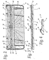
- a sheet cutting apparatus is shown at 10.
- the sheet cutting apparatus is useable to cut/trim sheet product 12 (Fig. 1).
- the sheet product 12 may be paper, such as used for letters or processing photographs, light cardboard, or other sheet material that lends itself to being severed by a translating cutting blade.
- the sheet cutting apparatus 10 has a generally rectangular base 14 having a flat, upwardly facing surface 16 to support the sheet material 12 strategically for a cutting/trimming operation.
- the support surface 16 is bounded by spaced edges 18, 20, which determine the cutting width capacity W (Fig. 1) of the sheet cutting apparatus 10.
- An elongate ruler element 21 is pivotable between an operative position, as shown in solid lines in Fig. 5, and a stored position, as shown in dotted lines in Fig. 5 and in solid lines in Fig. 3. In the operative position, the ruler element 21 extends the effective support area for the surface 16.
- the edges 18, 20 extend parallel to each other and orthogonal to a cutting line L (Fig. 1) as will be explained in greater detail below.
- the support surface 16 has markings and graduations 22 thereon to facilitate strategic placement of the sheet material 12 preparatory to a cutting/trimming operation.
- the basic sheet cutting apparatus 10 has the capacity to cut/trim a single layer, or multiple layers, of sheet material 12.
- the sheet material 12 that is to be cut/trimmed is placed upon the support surface 16 and directed to within a space 23 (see also Fig. 8) defined between a flat, downwardly facing surface 24 on a rail assembly 26 and the underlying, upwardly facing support surface 16.
- the rail assembly 26 is mounted so as to "float" vertically to allow the vertical dimension of the space 23 to be varied.
- the rail assembly 26 incorporates aspects of the design disclosed in U.S. Patent No. 5,671,647, to Mori, which is incorporated herein by reference.
- the rail assembly 26 consists of first and second elongate rail portions 28, 30 united by curved, opposite end portions 32, 34.
- a blade assembly 36 having a cutting blade 38 (Fig. 3) is mounted to the rail portions 28, 30 to be guided in the cutting path within an elongate slot 40, defined between the rail portions 28, 30.
- the cutting blade 38 projects downwardly into an elongate depression 41 in the support surface 16 so that the cutting blade 38 consistently extends fully through the sheet product thereon to ensure complete cutting thereof.
- the base 14 has convexly shaped, raised portions 42, 44 which respectively define receptacles 46, 48 (Fig. 10) for the end portions 32, 34, respectively.
- the raised portions 42, 44 have edges 50, 51 at the entries to the receptacles 46, 48.
- the edges 50, 51 are spaced from each other a distance L1, which is less than the combined length L2 of the rail portions 28, 30 and end portions 32, 34 between the edges 52, 53 thereof, with the rail assembly 26 in a relaxed state.
- L1 which is less than the combined length L2 of the rail portions 28, 30 and end portions 32, 34 between the edges 52, 53 thereof, with the rail assembly 26 in a relaxed state.
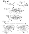
- each spring 70 has a generally V-shaped body 72 with outturned ends 74, 76.
- Mounting posts 78 on the base 14 project through an opening 80 in each leaf spring body 72 to maintain the leaf springs 70 in an operative position within spaced receptacles 80, 81, respectively beneath the rail end portions 32, 34.
- the spring 70 is shown in Fig. 6 in an undeformed state.
- the end portion 32 becomes resiliently supported upon the outturned ends 74, 76 of the spring 70.
- the spring 70 is slightly loaded by being compressed downwardly, as shown in Fig. 8, so as to resiliently bias the rail assembly 26 upwardly.
- the space 23 between the surfaces 16, 24, which accommodates the sheet product 12 has a maximum dimension D.
- the rail assembly 26 can be pressed downwardly to bring the surfaces 16, 24 into abutting relationship and to thereby virtually eliminate the space 23. Accordingly, the user can press the rail assembly 26 downwardly towards the support surface 16 to captively hold the sheet product 12, be it one or a multitude of layers.
- the rail assembly 26 is confined against skewing in a plane parallel to the plane of the support surface 18 by the cooperation between edges 82, 84 on the rail assembly 26 and confronting surfaces on each of the raised portions 42, 44.
- the raised portion 42 has edges 86, 88 which abut to the rail assembly edges 82, 84. Edges 90, 92 on the raised part 44 and the edges 82, 84 cooperate in like manner.
- the cooperating edges 86, 88; 90, 92 and 82, 84 maintain the rail assembly 26 in a desired orientation within a horizontal plane. Accordingly, the rail assembly end portions 32, 34 are fixed against substantially all but vertical floating movement relative to the raised portions 42, 44.
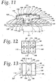
- the blade assembly 36 consists of a molded body 96 with a generally squared gripping portion 98 from which a stem 100 depends.
- the gripping portion 100 has a textured upper surface 101 to facilitate a comfortable frictional engagement by a user's finger.
- the cutting blade 38 is embedded in the stem 100.
- the stem 100 as viewed from the ends thereof, has an inverted "T" shape, which defines, in conjunction with the gripping portion 98, oppositely opening, U-shaped receptacles 102, 104 to respectively receive the rail portions 28, 30, with the blade assembly 36 in the operative state of Fig. 11.
- the receptacle 102 is bounded by a base portion 106, which is straight and extends the full length L3 of the body 96.
- the base portion 106 confronts a straight, free edge 108 on the first rail portion 28.
- a like base portion 110 bounding the receptacle 104 confronts a free edge 112 on the rail portion 30 along an equal length L3.
- the cross bar 114 of the "T" on the stem 100 defines upwardly facing surfaces 116, 118, which respectively cooperate with downwardly facing surfaces 120, 122 on the gripping portion 98 to captively hold the rail portions 28, 30 in place in a vertical direction.
- the rail portions 28, 30 have undercuts 124, 126 which receive depending arms 128, 130 on the gripping portion 98.
- the rail assembly 26 and blade assembly 36 are designed so that the blade assembly 36 can be separated therefrom, as to effect change or repair of the blade assembly 36. Separation of the blade assembly 36 is accomplished by enlarging the width W (Fig. 5) of the slot 40 sufficiently to allow passage therethrough of the width W1 (Fig. 11) of the crossbar 114 on the stem 100. At the ends of the rail assembly, the spacing between the rail portions 28, 30 is maintained by the end portions 32, 34. The greatest flexibility of the rail portions 28, 30 exists midway between the end portions 32, 34. It is at this location that installation and removal of the blade assembly 36 preferably takes place.
- the entire rail assembly 26, or at least the rail portions 28, 30, are made from a plastic material.
- the goal of accurately guiding movement of the blade assembly 36 competes with the goal of allowing the rail portions 28, 30 to be separated to facilitate installation and separation of the blade assembly 36.
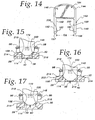
- a change tool 142 is utilized to remove the blade assembly 36 from its operative position and also may be used to effect installation of the blade assembly 36 into its operative state.
- the change tool 142 consists of a generally U-shaped body 144 with a base portion 146, from which first and second legs 148, 150, project.
- the base portion 146 has undercut, oppositely opening, receptacles 152, 154, within which a user's fingers can be situated to grasp the tool 142.
- the legs 148, 150 have divergent, cam surfaces 156, 157 at their free ends.
- the legs 148, 150 have facing surfaces 158, 159 from which first and second projections 160, 162 extend.
- the first and second legs 148, 150, including the projections 160, 162 have the same construction and are mounted to the base portion 146 so as to be mirror images of each other.
- the facing leg surfaces 158, 159 are spaced from each other a distance D2 (Fig. 14), which is slightly greater than the dimension L3 (Fig. 13) between oppositely facing surfaces 164, 166 of the gripping portion 98 of the body 96 of the blade assembly 36.
- the change tool 142 is aligned over the blade assembly 36 in an orientation wherein the legs 148, 150 extend generally vertically.
- the legs 148, 150 in this first orientation are situated to straddle the surfaces 164, 166 on the body 96 of the blade assembly 38, midway between oppositely facing surfaces 168, 170, each extending between the surfaces 164, 166 on the body 96 of the blade assembly 36.
- the guide receptacles 172, 174 have the same configuration.
- Exemplary guide receptacle 172 as shown in detail in Fig. 11, has a vertically extending portion 176 which blends into a concave, upwardly opening shoulder portion 178.
- the cooperating projections 160, 162 and guide receptacles 172, 174 guide movement of the change tool 142 in a predetermined path relative to the blade assembly 36.
- a sequence of steps for moving the change tool 142 in the predetermined path from a first, separated position in Fig. 18, to a second, fully engaged position in Fig. 21, is shown. Since the cooperation between each of the legs 148, 150 and projections 160, 162 and the blade assembly 36 is the same, the cooperation between exemplary leg 148 and projection 160 will be described in the sequenced drawings in Figs. 18-21.
- the change tool 142 has the previously described orientation with the legs 148, 150 aligned over the guide receptacles 172, 174.
- the projection 160 moves into the guide receptacle 172 simultaneously as the projection 162 moves into the guide receptacle 174.
- the projection 160 has an angled cam surface 180 and a free end 182. As downward movement of the change tool 142 continues in the direction of the arrow 184 in Fig. 19, the cam surface 180 and free end 182 on the projection 160 cooperate with the receptacle portions 176, 178 to guide the leg 148 to the Fig. 19 position.
- the cam surface 180 and free end 182 on the projection 160 cooperate with the receptacle portions 176, 178 to guide the leg 148 to the Fig. 19 position.
- the free end 182 of the projection 160 aligns with the vertically extending portion 176 of the guide receptacle 172.
- a corresponding free end 184 on the projection 162 aligns with the vertically extending portion 186 of the guide receptacle,174, corresponding to the vertically extending portion 176.
- the spacing between the free ends 182, 184 of the projections 160, 162 is slightly less than the spacing between the vertically extending portions 176,186.
- the legs 150 bow slightly outwardly, which is shown in an exaggerated state in Fig. 19, so that there is a residual, captive, bias force produced by the free ends 182, 184 of the projections 160, 162 upon the body 96 of the blade assembly 36.
- an upwardly facing shoulder 200 on the projection 160 is situated in confronting relationship with a downwardly facing shoulder 202 that bounds the receptacle 194.
- a shoulder 206 on the projection 162 is situated in confronting relationship with a shoulder 208 bounding the receptacle 196.
- Figs. 15-17 a sequence of drawings is shown for the change tool 142 being moved downwardly, as in Figs. 18-21, but from a prospective rotated 90° from that in Figs. 18-21.
- Figs. 15-17 the interaction of exemplary leg 148 with the blade assembly 36 is shown.
- the leg 150 operates simultaneously in the same manner.
- the cam surface 156 on the leg 148 has a truncated, V-shaped configuration with angled cam edge portions 214, 216.
- the cam edge portions 214, 216 are configured to cooperate with corners 218, 220 on the rail portions 28, 30, respectively.
- the cam edge portions 214, 216 simultaneously engage the corners 218, 220, as shown in Fig. 15.
- the rail portions 28, 30 to be wedged by the cam edge portions 214, 216 to thereby progressively separate, and in so doing, enlarging the slot 40 to the point in Fig. 16 wherein it will accommodate the full width W1 (Figs. 11 and 13) of the cross bar 114 on the stem 100 on the sleeve assembly 36.
- the Fig. 16 position for the change tool 142 corresponds to the Fig. 21 position wherein the projections 160, 162 seat in the receptacles 194, 196.
- the change tool 142 can be moved from its first separated position into the second position shown in Figs. 16 and 21, wherein the change tool 142 and blade assembly 36 are releasably maintained together and the slot 40 is enlarged to allow passage through of the stem 100 of the blade assembly 36. By then releasing the downward force, the blade assembly 36 releases itself together with the change tool142.
- the change tool 142 can likewise be used to facilitate placement of the blade assembly 36 into the operative state.
- the change tool 142 and blade assembly 36 are releasably maintained together with the projections 160, 162 residing in their respective receptacles 172, 174.
- the change tool 142, with the blade assembly 36 held thereby, can be moved to a position wherein the blade assembly 36 is aligned over the slot 40. By then exerting a downward pressure, the change tool 142 assists the advancement of the blade assembly 36 into the operative position.
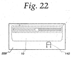
- the sheet cutting apparatus 10 can be sold in conjunction with the change tool 142 as a kit.
- a container 228 maintains the sheet cutting assembly 10 and change tool 142 in a unitary package that is suitable for display.
Landscapes
- Engineering & Computer Science (AREA)
- Mechanical Engineering (AREA)
- Life Sciences & Earth Sciences (AREA)
- Forests & Forestry (AREA)
- Details Of Cutting Devices (AREA)
- Nonmetal Cutting Devices (AREA)
Applications Claiming Priority (2)
| Application Number | Priority Date | Filing Date | Title |
|---|---|---|---|
| US429061 | 1982-09-30 | ||
| US10/429,061 US7347132B2 (en) | 2003-05-02 | 2003-05-02 | Sheet cutter |
Publications (2)
| Publication Number | Publication Date |
|---|---|
| EP1473124A2 true EP1473124A2 (de) | 2004-11-03 |
| EP1473124A3 EP1473124A3 (de) | 2005-06-08 |
Family
ID=32990493
Family Applications (1)
| Application Number | Title | Priority Date | Filing Date |
|---|---|---|---|
| EP20040009607 Withdrawn EP1473124A3 (de) | 2003-05-02 | 2004-04-22 | Bogenschneider |
Country Status (5)
| Country | Link |
|---|---|
| US (1) | US7347132B2 (de) |
| EP (1) | EP1473124A3 (de) |
| JP (1) | JP2004330408A (de) |
| CN (1) | CN1590044A (de) |
| AU (1) | AU2004201856A1 (de) |
Families Citing this family (20)
| Publication number | Priority date | Publication date | Assignee | Title |
|---|---|---|---|---|
| US20060156885A1 (en) * | 2005-01-19 | 2006-07-20 | Wu Michael Y | Cutter assembly of paper cutting device |
| USD593598S1 (en) | 2005-11-08 | 2009-06-02 | Acme United Corporation | Paper trimmer and scorer |
| US7261484B2 (en) * | 2005-11-08 | 2007-08-28 | Thomas Gallagher | Loss prevention device for pens |
| EP1973683A2 (de) * | 2006-01-20 | 2008-10-01 | Inovent LLC | Schneidegerät für gerollte medien |
| US20080264227A1 (en) * | 2007-04-10 | 2008-10-30 | Acco Brands Usa Llc | Sheet trimmer |
| US8132490B2 (en) * | 2007-06-26 | 2012-03-13 | Acme United Corporation | Rotary trimmer |
| CN101835572A (zh) * | 2007-07-03 | 2010-09-15 | 大卫·平特 | 切割组件 |
| USD581972S1 (en) | 2008-01-09 | 2008-12-02 | Acco Brands Usa Llc | Sheet trimmer |
| US20100132522A1 (en) * | 2008-09-19 | 2010-06-03 | Peterson Michael E | Trimmer |
| US20120111169A1 (en) * | 2010-11-09 | 2012-05-10 | Blalock Stephen J | Sheet Cutting Apparatus |
| USD734813S1 (en) * | 2013-04-16 | 2015-07-21 | Eric Hales | Trimming tool |
| US20150047484A1 (en) * | 2013-08-16 | 2015-02-19 | Richard P. Lane | Saw cutting guide |
| US9232769B1 (en) * | 2014-08-29 | 2016-01-12 | Alan Neil Wolf | Method and apparatus for automatically dispensing wet pet food |
| CN105364956B (zh) * | 2014-09-02 | 2017-07-28 | 正大天晴药业集团股份有限公司 | 一种泡罩型包材的手动切割装置 |
| US20170036365A1 (en) * | 2015-08-04 | 2017-02-09 | Gary DARWIN | Sheet material cutting guide and ruler |
| USD844701S1 (en) * | 2016-08-10 | 2019-04-02 | Parric Ningbo Stationery And Gifts Mfg. Co., Ltd. | Paper trimmer |
| US11077576B1 (en) * | 2017-09-26 | 2021-08-03 | Harry Eugene Talbott | Tile cutting device |
| WO2022170153A1 (en) * | 2021-02-05 | 2022-08-11 | George Jones | Wrapping paper storage and dispensing device |
| USD1055658S1 (en) * | 2022-02-17 | 2024-12-31 | Tonic Studios Limited | Trimmer |
| USD1055659S1 (en) * | 2022-02-17 | 2024-12-31 | Tonic Studios Limited | Trimmer |
Family Cites Families (14)
| Publication number | Priority date | Publication date | Assignee | Title |
|---|---|---|---|---|
| US3368594A (en) * | 1966-04-18 | 1968-02-13 | Allen L. Drumbore | Miter guide for portable power saws |
| US3741063A (en) * | 1972-04-06 | 1973-06-26 | F Bretthauer | Adjustable jig for portable electric saws |
| US3964360A (en) * | 1975-12-22 | 1976-06-22 | Joseph Schwartz | Sheet material cutting apparatus |
| US4489634A (en) * | 1982-07-28 | 1984-12-25 | Volk Michael J | Portable power tool table |
| US4516324A (en) * | 1982-11-01 | 1985-05-14 | Black & Decker Inc. | Modular housing system for a circular saw |
| US5461944A (en) * | 1986-12-08 | 1995-10-31 | Ciumaga; Massimo | Method of making a screwdriver |
| JPH06262586A (ja) * | 1993-03-16 | 1994-09-20 | Karl Jimuki Kk | 紙截断機 |
| US5322001A (en) * | 1993-05-28 | 1994-06-21 | Fiskars Oy Ab | Paper cutter with circular blades |
| US5442984A (en) * | 1993-12-09 | 1995-08-22 | Tate; Terrance | Sheet material table and cutting guide assembly |
| US5802942A (en) * | 1995-10-10 | 1998-09-08 | Fiskars Inc. | Paper trimmer |
| US6460443B1 (en) * | 2001-01-12 | 2002-10-08 | Tex Year Industries Inc. | Device for cutting sheet materials |
| US20030140760A1 (en) * | 2002-01-25 | 2003-07-31 | Steven Bory | Film cutter |
| US20030140757A1 (en) * | 2002-01-25 | 2003-07-31 | Alterra Holdings Corporation | Storage compartment for a paper trimmer |
| DE20201841U1 (de) * | 2002-02-07 | 2002-07-18 | NWS Germany Produktion W. Nöthen e.K., 42719 Solingen | Montagezange |
-
2003
- 2003-05-02 US US10/429,061 patent/US7347132B2/en not_active Expired - Fee Related
-
2004
- 2004-03-30 JP JP2004099851A patent/JP2004330408A/ja active Pending
- 2004-04-22 EP EP20040009607 patent/EP1473124A3/de not_active Withdrawn
- 2004-04-30 CN CNA200410043444XA patent/CN1590044A/zh active Pending
- 2004-04-30 AU AU2004201856A patent/AU2004201856A1/en not_active Abandoned
Also Published As
| Publication number | Publication date |
|---|---|
| EP1473124A3 (de) | 2005-06-08 |
| JP2004330408A (ja) | 2004-11-25 |
| CN1590044A (zh) | 2005-03-09 |
| US20040216571A1 (en) | 2004-11-04 |
| AU2004201856A1 (en) | 2004-11-18 |
| US7347132B2 (en) | 2008-03-25 |
Similar Documents
| Publication | Publication Date | Title |
|---|---|---|
| US7347132B2 (en) | Sheet cutter | |
| US7175023B2 (en) | Chisel scabbard with removable insert | |
| CN1239881C (zh) | 一种装卡便携式装置的夹具 | |
| EP0908327A2 (de) | Handvorrichtung zum Binden mit Stanzvorrichtung | |
| JPH0718857U (ja) | 書類綴じ具 | |
| GB2294003A (en) | Punch for making a multiplicity of holes | |
| US5893313A (en) | Corner cutter | |
| AU703275B2 (en) | Cheese slicer | |
| IL138364A (en) | Sheet fixing device | |
| US20060266191A1 (en) | Dual function apparatus for cutting and punching | |
| CN218015158U (zh) | 一种冲切装置、制带机构及焊接设备 | |
| US4455736A (en) | Staple removing apparatus | |
| US20020043141A1 (en) | Cutting device | |
| JP2000301497A (ja) | ゲージパンチ | |
| JPH0970793A (ja) | コーナカッター | |
| JP2005014158A (ja) | 穴あけ綴じ具 | |
| JP2012121091A (ja) | 裁断機及び裁断機用スライダ | |
| CN110744592A (zh) | 一种墙纸裁切器 | |
| JP3055715U (ja) | メモホルダー | |
| WO2017074293A1 (en) | Corner punching device | |
| CN2710925Y (zh) | 美工刀 | |
| JP4178303B2 (ja) | グリーンシートのカット装置 | |
| JPS58556Y2 (ja) | 綴り具 | |
| JP6232529B1 (ja) | 綴じ部を有するシート及びその綴じ方法 | |
| JP3049097U (ja) | ステープラー |
Legal Events
| Date | Code | Title | Description |
|---|---|---|---|
| PUAI | Public reference made under article 153(3) epc to a published international application that has entered the european phase |
Free format text: ORIGINAL CODE: 0009012 |
|
| AK | Designated contracting states |
Kind code of ref document: A2 Designated state(s): AT BE BG CH CY CZ DE DK EE ES FI FR GB GR HU IE IT LI LU MC NL PL PT RO SE SI SK TR |
|
| AX | Request for extension of the european patent |
Extension state: AL HR LT LV MK |
|
| PUAL | Search report despatched |
Free format text: ORIGINAL CODE: 0009013 |
|
| AK | Designated contracting states |
Kind code of ref document: A3 Designated state(s): AT BE BG CH CY CZ DE DK EE ES FI FR GB GR HU IE IT LI LU MC NL PL PT RO SE SI SK TR |
|
| AX | Request for extension of the european patent |
Extension state: AL HR LT LV MK |
|
| 17P | Request for examination filed |
Effective date: 20051025 |
|
| AKX | Designation fees paid |
Designated state(s): DE FR GB NL |
|
| STAA | Information on the status of an ep patent application or granted ep patent |
Free format text: STATUS: THE APPLICATION IS DEEMED TO BE WITHDRAWN |
|
| 18D | Application deemed to be withdrawn |
Effective date: 20060904 |