EP1469901B1 - Guide wire - Google Patents
Guide wire Download PDFInfo
- Publication number
- EP1469901B1 EP1469901B1 EP03701901A EP03701901A EP1469901B1 EP 1469901 B1 EP1469901 B1 EP 1469901B1 EP 03701901 A EP03701901 A EP 03701901A EP 03701901 A EP03701901 A EP 03701901A EP 1469901 B1 EP1469901 B1 EP 1469901B1
- Authority
- EP
- European Patent Office
- Prior art keywords
- coil
- distal end
- guide wire
- elongate member
- wire
- Prior art date
- Legal status (The legal status is an assumption and is not a legal conclusion. Google has not performed a legal analysis and makes no representation as to the accuracy of the status listed.)
- Expired - Lifetime
Links
Images


Classifications
-
- A—HUMAN NECESSITIES
- A61—MEDICAL OR VETERINARY SCIENCE; HYGIENE
- A61M—DEVICES FOR INTRODUCING MEDIA INTO, OR ONTO, THE BODY; DEVICES FOR TRANSDUCING BODY MEDIA OR FOR TAKING MEDIA FROM THE BODY; DEVICES FOR PRODUCING OR ENDING SLEEP OR STUPOR
- A61M25/00—Catheters; Hollow probes
- A61M25/01—Introducing, guiding, advancing, emplacing or holding catheters
- A61M25/09—Guide wires
- A61M2025/09058—Basic structures of guide wires
- A61M2025/09083—Basic structures of guide wires having a coil around a core
Definitions
- the present invention relates to a guide wire used for introducing a catheter into a body cavity such as a blood vessel.
- a guide wire is inserted through the catheter and the distal end of the guide wire goes ahead of the catheter while a desired path is properly selected whenever the guide wire meets a diverging point of blood vessels as branching off like a labyrinth.
- Such a guide wire was disclosed by the gazette of USP 4,538,622.
- the guide wire is equipped with a wire body, which is a cylindrically shaped element, a first metal coil, a second coil, and a rounded structure.
- the first coil is fixed to the distal end of the wire body.
- the second coil is fixed to the distal end of the first coil.
- the rounded structure is fixed to the second coil.
- the jointed part of the first and the second coils is fixed to the wire body, which is inserted through the coils, by means of a soldering or brazing material.
- the brazing material and the rounded structure is bridged by a safety ribbon (refer to Fig. 2 and others of the above gazette).
- the safety ribbon is a separate component independent from the first coil and the second coil. Therefore, it presents a shortcoming that the fixed end of the safety ribbon may come loose when the safety ribbon is under a tensile strength during the reshaping process. When there is a concern for the safety ribbon to come off, the distal end of the guide wire cannot be formed into a desired shape and a sufficient reshaping effect may not be achieved.
- the wire body is made of Ni-Ti alloy for the benefit of super elasticity, the reshaping process is particularly difficult.
- a safety ribbon made of a material that can be reshaped easily such as stainless steel separate from the wire body.
- the wire body is made of a Ni-Ti alloy, the wettability of soldering is poor, thus resulting in poor joint strength. Therefore, although the safety ribbon is provided, the fixation of the wire body and the coil or others can come loose, so that the safety ribbon, which is provided independently, can also come loose due to the force applied during the reshaping process.
- a guide wire of the invention includes a wire body, a first coil, a second coil, and an elongate member.
- the first coil has a helical shape, and is disposed on a distal end side of the guide wire.
- the second coil has a helical shape, and is disposed on a distal end side of the first coil.
- the elongate member has a section that extends a longitudinal direction of the wire body. At least a portion of the section is located inside the second coil, and the elongate member is formed integrally with the first coil or the second coil. This makes it possible to achieve the reshaping of the distal end of the guide wire more easily and securely.
- a guide wire of the invention includes a wire body, a helical coil, and an elongate member.
- the helical coil has a distal end and a proximal end and is disposed on a distal end side of the wire body.
- the elongate member extends from the distal end or the proximal end of the coil, is disposed inside the coil, formed integrally with the coil, and made of a material that can be reshaped.
- a guide wire of the invention includes a distal end side wire, a proximal side wire, a helical coil, and an elongate member.
- the distal end side wire is made of Ni-Ti alloy.
- the proximal side wire is made of a material with rigidity higher than that of said distal end side wire.
- the helical coil has a distal end and a proximal end, is disposed on the distal end side wire, and is radiopaque at least at the distal end thereof.
- the elongate member can be reshaped, is made of the same material as the coil, and extends into inside of the coil from either the distal end or the proximal end of the coil.
- a guide wire 1 shown in Fig. 1 is used as inserted into a catheter that is introduced into a body cavity such as a blood vessel.
- the guide wire 1 includes a wire body 2, which is a core wire, a first coil 3 having a helical shape, a second coil 4 having a helical shape, and at least one elongate member 35.
- the wire body 2 is a main part of a guide wire 1.
- the first coil 3 is located on the distal end side of the wire body 2.
- the second coil 4 is located on the distal end side of the first coil 3 and is jointed there.
- the elongate member 35 has a section that extends in the lengthwise direction of the wire body 2. Moreover, a part of the extending portion is located inside the second coil 4.
- the wire body 2 is preferably made of a metallic material and consists of a body section 20, a first taper section 21, an intermediate section 22, a second taper section 23, and a small diameter section 24 as shown in Fig. 1.
- the body section 20 has a relatively large diameter.
- the first taper section 21 and the second taper section 23 are both located toward the distal end direction away from the body section 20.
- the outer diameters of the first taper section 21 and the second taper section 23 reduce gradually toward the distal end direction.
- the intermediate section 22 is located between the first taper section 21 and the second taper section 23.
- the outer diameter of the intermediate section 22 is substantially constant in the longitudinal direction.
- the small diameter section 24 is located toward the distal end direction away from the second taper section 23.
- a portion of the wire body 2 located on the distal end side relative to the first taper section 21 is inserted substantially in center of the inside of the first coil 3 or the second coil 4.
- the portion of the wire body 2 is inserted inside the first coil 3 and the second coil 4 without contacting them.
- a portion of the proximal side of the first coil 3 may be contacting the wire body 2.
- the metal that forms the wire body 2 can be stainless steel or a super elasticity alloy such as Ni-Ti base alloy.
- the guide wire 1 Since the guide wire 1 has the first taper section 21 and the second taper section 23, the rigidity of the wire body 2 can be reduced gradually toward the distal end direction. Therefore, it is possible to increases its maneuverability in the insertion process without causing any bending problems.
- the wire body 2 can be formed by using a single material such as stainless steel or Ni-Ti alloy, or a combination of different materials.
- "Ni-Ti alloy” may have a third element, such as copper (Cu), aluminum (Al), iron (Fe), zinc (Zn) or cobalt (Co) may be used.
- the body section 20 which is located on the proximal side, with a material of a relatively high rigidity such as stainless steel, and form the sections located on the distal end side away from the body section 20, i.e., the first taper section 21, the intermediate section 22, the second taper section 23, and the small diameter section 24 of the first embodiment with a material of a smaller rigidity than stainless steel, for example, Ni-Ti alloy.
- the guidewire 1 can have excellent insertion characteristic and torque transmissibility, thus providing an excellent maneuverability. Moreover, the distal end side of the guidewire 1 provides excellent flexibility and recovery capability, resulting in an improved blood vessel following capability and safety.
- the combination of different materials in the wire body 2 is not limited to the above example but can be arbitrarily selected depending on the purpose.
- at least one of the intermediate section 22, the second taper section 23, and the small diameter section 24 is made of stainless steel, it is possible to improve the shape preserving capability in the reshaping process.
- the body section 20 and the sections away from the body section 20 toward the distal end direction with the same material, such as Ni-Ti alloy, but with different rigidity characteristics, thus causing the body section 20 and the sections away from the body section 20 toward the distal end direction to have different rigidity characteristics.
- the body section 20 can be so arranged that the body section 20 to have a higher rigidity due to the difference in materials compared to the sections away from the body section 20 toward the distal end direction.
- the first coil 3 is preferably made of a metallic material.
- the helical part of the first coil 3 should be densely formed so that no gaps exist in a state when no external force is applied.
- the metallic material that forms the first coil 3 can be stainless steel, super elastic alloy such as Ni-Ti alloy, shape memory alloy, or cobalt base alloy.
- the first coil 3 can also be made of a radiopaque material, which is described later.
- the proximal section of the first coil 3 is fixed to the first taper section 21 of the wire body 2.
- the fixing method is not limited in particular.
- a fixing material 5 such as soldering or brazing material is used as shown in Fig. 1.
- Other fixing methods are, for example, welding or bonding with an adhesive material.
- the second coil 4 is preferably made of a metallic material.
- the helical part of the second coil 4 should be densely formed so that no gaps exist in a state when no external force is applied.
- the metallic material that forms the second coil 4 can be stainless steel, super elastic alloy such as Ni-Ti alloy, shape memory alloy, cobalt base alloy, a precious metal, or an alloy containing the precious metal.
- the precious metal can be gold, platinum, and tungsten.
- the second coil 4 from a radiopaque material, such as a precious metal. By doing so, it is possible to insert the guide wire 1 into a living body while monitoring the position of the distal end of the guide wire 1 under the X-ray radioscopy as the guide wire 1 generates an X-ray image.
- a radiopaque material such as a precious metal
- the elongate member 35 that extends from the distal end of the first coil 3 is to be made of the same alloy.
- the elongate member 35 is required being heat treated or cold formed for the reshaping capability.
- the second coil 4 is made of a radiopaque material such as stainless steel, it is possible to form a layer made of a radiopaque material as mentioned above on at least a part of either one of the surfaces of the second coil 4, the elongate member 35 to be described later, and the small diameter section 24. Since the guide wire 1 generates an X-ray image in this case as well, it is possible to insert the guide wire 1 into a living body while monitoring the position of the distal end of the guide wire under the X-ray radioscopy.
- a radiopaque material such as stainless steel
- the proximal end of the second coil 4 is connected and fixed to the distal end of the first coil 3.
- the disposing and fixing methods for the first coil 3 and the second coil 4 are not limited in particular. In the first embodiment, it is so disposed that a portion of the first coil 3 overlaps a portion of the second coil 4.
- the helical windings of the first coil 3 and the second coil 4 are intermeshing with each other in a joint section 33 where the first coil 3 and the second coil 4 are connected.
- the helical windings of the first coil 3 and the second coil 4 are intermeshed together in such a way that each winding of them appears between the windings of the other coil.
- the first coil 3 and the second coil 4 can be disposed accurately concentric with each other as they are being assembled.
- a force is applied in such away as to pull the guide wire 1 toward the distal end direction, such an arrangement effectively prevent its separation from the joint section 33.
- the joint section 33 is fixed to the second taper section 23 of the wire body 2.
- the fixing method is not limited in particular.
- a fixing material 6 such as soldering or brazing material, is used as shown in Fig. 1 and Fig. 2. This makes the strength of connection of the first coil 3 and the second coil 4 to the wire body 2 stronger.
- Other fixing methods can be welding and bonding with adhesive.
- wires with circular cross sections are used for the first coil 3 and the second coil 4 in the first embodiment, the invention is not limited by them. Wires with elliptical, rectangular, in particular, of oblong cross sections can be used as well.
- the material, diameter or thickness, and cross-sectional shape of wires used for the first coil 3 and the second coil 4, as well as the helical pitch, outer diameter, inner diameter, etc., of the first coil 3 and the second coil 4 can be equal or different.
- the surfaces of the first coil 3 and/or the second coil 4, in particular, the entire or a portion of the outer surface thereof, should preferably be coated with a hydrophilic or hydrophobic material (not shown). This makes the insertion of the guide wire 1 smoother.
- Such a coating can be made in various configurations depending on the purpose. For example, modifications 1 through 3 shown below are some of them.
- a lubricating hydrophobic coating is applied on the entire outer surfaces of the first coil 3 and the second coil 4.
- a lubricating hydrophobic coating is applied on a portion of the second coil 4 for a predetermined length on the distal end of the second coil 4, while a hydrophilic coating is formed on the first coil 3 and other part of the second coil 4.
- no coating is applied on a portion of the second coil 4 for a predetermined length on the distal end of the second coil 4, while a hydrophilic or hydrophobic coating is formed on the first coil 3 and other part of the second coil 4.
- the hydrophilic material for forming the coating can be cellulose polymeric materials, polyethylene oxide polymeric materials, maleic anhydride polymeric materials, acrylamide polymeric materials, water soluble Nylon, and polyvinyl alcohol.
- the maleic anhydride polymeric materials can be, for example, maleic anhydride copolymers such as methylvinylether-anhydride copolymer.
- the acrylamide polymeric materials here can be block copolymers of polyglycidyl methacrylate-dimethyl acrylamide (PGMA-DMAA).
- the hydrophobic material for forming the coating can be fluorocarbon resins such as polytetrafluoroethylene and silicone materials. The coating can be formed on the surface of the wire 2 as well.
- the elongate member 35 is disposed on the distal end of the first coil 3.
- the elongate member 35 is formed to extend from the distal end of the first coil 3, while extending substantially parallel to the small diameter section 24 inside the second coil 4.
- the existence of the elongate member 35 makes it possible to easily and securely execute the aforementioned reshaping process. For example, if a doctor is reshaping the distal end of the guide wire 1 using the fingers, the elongate member 35 makes a plastic deformation to produce a desired shape and serves the purpose of maintaining the desired shape.
- the materials of the elongate member 35 and the first coil 3 are the same, and the elongate member 35 is formed integrally with the first coil 3. Therefore, it requires a fewer parts compared to a case of forming the elongate member 35 as a separate part, thus enabling it to assemble, i.e., produce the guide wire 1 easily.
- the elongate member 35 is disposed on the center axis or the vicinity of the center axis of the cylinder of the first coil 3.
- the elongate member 35 can be formed, for example, during the process of forming the first coil 3 from a wire material, i.e., the coiling process.
- the length of the elongate member 35 is not limited in particular, but it is preferable to be 0.5 to 4.0 cm, and is more preferable to be 1.5 to 3.0 cm.
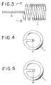
- the cross sectional area of the entire or a portion of the elongate member 35 should preferably be smaller than the cross sectional area of the wire that forms the first coil 3 or the second coil 4. Specifically, if the cross-sectional shape of the wire material used to form the elongate member 35 and the first coil 3 happens to be circular, the outer diameter of the elongate member 35 is preferably smaller than the outer diameter of the wire material that forms the first coil 3 as shown in Fig. 4. By using such a configuration, a better flexibility can be secured.
- the cross-sectional shape of the elongate member 35 can be quadrangular such as square, rectangular, and trapezoidal.
- the elongate member 35 can be a flat plate or a rectangular rod.
- Such a flat plate-like or rectangular rod-like portion can be formed only in certain part of the elongate member 35.
- the cross-sectional shape of the elongate member 35 can be constant over the entire length.
- the elongate member 35 can have a portion where the cross-sectional shape changes continuously, i.e., increase or decrease continuously.
- the shape that is applicable to the elongate member 35 with a circular cross section as shown in Fig. 3 and Fig. 4, can be a shape wherein the outer diameter is constant over the entire length, a shape wherein the outer diameter is gradually decreasing toward the distal end direction, a shape wherein the outer diameter is constant partially, and a shape that has a portion wherein the outer diameter is gradually decreasing toward the distal end direction.
- the elongate member 35 has a portion whose cross section area reduces or reduces gradually toward the distal end direction.
- the elongate member 35 according to the modification 1 shown in Fig. 6A has a rectangular cross section shape.
- the length of the longer side L 1 of the rectangle is substantially constant along the longitudinal direction of the elongate member 35.
- the length of the shorter side L 2 of the rectangle reduces gradually toward the direction of the distal end 36 of the elongate member 35.
- the length L 2 of the shorter side of the rectangle reduces gradually or in steps.
- the elongate member 35 according to the modification 2 shown in Fig. 6B has a rectangular cross section shape.
- the length of the shorter side L 2 of the rectangle is substantially constant along the lengthwise direction of the elongate member 35.
- the length of the longer side L 1 of the rectangle reduces gradually toward the direction of the distal end 36. In other words , the length L 1 of the longer side reduces gradually or in steps.
- the elongate member 35 according to the modification 3 shown in Fig. 6C has a rectangular cross section shape.
- the length of the longer side L 1 of the rectangle reduces gradually toward the direction of the distal end 36.
- the length of the shorter side L 2 of the rectangle reduces gradually toward the direction of the distal end 36.
- both the length L 1 of the longer side and the length L 2 of the shorter side reduce gradually or in steps.
- the elongate member 35 according to the modification 4 shown in Fig. 6D has a rectangular cross section shape.
- the length of the longer side L 1 of the rectangle increases gradually toward the direction of the distal end 36. In other words, the length of the longer side L 1 of the rectangle increases gradually or in steps.
- the length of the shorter side L 2 of the rectangle decreases gradually toward the direction of the distal end of the elongate member 35. In other words, the length of the shorter side L 2 of the rectangle reduces gradually or in steps.
- the cross-sectional area of the elongate member 35 represented as a product of the length of the longer side L 1 multiplied by the length of the shorter side L 2 can be substantially constant along the lengthwise direction of the elongate member 35.
- the elongate member 35 according to the modification 5 shown in Fig. 6E is divided into several branches in the middle of the lengthwise direction of the elongate member 35. Specifically, the elongate member 35 has two branches 35a and 35b in the arrangement shown in the drawing. The cross-sectional areas of the branches 35a and 35b should preferably reduce toward the direction of the distal end 36.
- the elongate member 35 formed as such increases its flexibility toward the distal end. Therefore, when the distal end of the guide wire 1 gets into contact with the blood vessel, the distal end of the guide wire 1 can bend very easily and smoothly so that any possible damage to the blood vessel may be prevented, thus improving the safety substantially.
- a coating of the aforementioned radiopaque material can be disposed on at least a portion of the surface of the elongate member 35. It will provide the X-ray imaging capability to the guide wire 1 regardless of materials of the second coil 4 and the small diameter section 24. Thus, it is possible to insert the guide wire 1 into a living body while monitoring the position of the distal end of the guide wire 1 under the X-ray radioscopy.
- the distal end of the elongate member 35 and the distal end of the second coil 4 are fixed to the distal end of the wire body 2.
- the fixing method is not limited in particular.
- a fixing material 7 such as soldering or brazing material, is used. This makes it possible to further increase the jointing strength between the first coil 3 and the second coil 4 and the wire body 2.
- Other fixing methods are, for example, welding or bonding with an adhesive material.
- the end face of the fixing material 7 should preferably be rounded.
- Fig. 7 through Fig. 11 show vertical sections of the guide wires according to the second through sixth embodiments.
- the descriptions of items that are identical to the corresponding items of the guide wire 1 of the first embodiment shown in Fig. 1 will not be repeated, and the descriptions will mainly be concentrated on the differences.
- the guide wire 1 according to the second embodiment shown in Fig. 7 is different from the first embodiment only in the configuration of the distal end of the wire body 2.
- the small diameter section 24 of the wire body 2 is adapted to be shorter and the distal end 25 of the small diameter section 24 is not fixed by the fixing material 7 but free. Since the distal end 25 of the small diameter section 24 is formed as a free end, the flexibility of the guide wire 1 is further improved.
- both ends of the elongate member 35 are fixed by the fixing materials 6 and 7 respectively, and the distal end 25 of the small diameter section 24 does not reach the fixing material 7. Consequently, the elongate member 35 serves the function of a "safety wire" for preventing the fall out of the second coil 4 in addition to the function of a reshaping member. For that reason, it can maintain a tensile strength even though the distal end 25 is a free end.
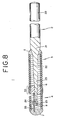
- the guide wire 1 according to the third embodiment shown in Fig. 8 is different from the first embodiment only in the configuration of the distal end of the wire body 2.
- the small diameter section 24 of the wire body 2 is adapted to be shorter and the distal end 25 of the small diameter section 24 is disposed and fixed in the middle of the elongate member 35.
- the fixing method is not limited in particular.
- a fixing material 8 such as soldering or brazing material, is used.
- Other fixing methods are, for example, welding or bonding with an adhesive material.
- the small diameter section 24 of the wire body 2 is fixed to the elongate member 35, the small diameter section 24 can follow the elongate member 35 easily when the distal end of the guide wire 1 is bent or curved. This improves the capability to follow blood vessels that run and/or branch in a complex manner and prevents the distal end 25 from exposing on the outside of the coil via the gaps formed between the wires as the second coil 4 elongates.
- both ends of the elongate member 35 are fixed by the fixing materials 6 and 7 respectively, and the distal end 25 of the small diameter section 24 does not reach the fixing material 7. Consequently, the elongate member 35 serves the function of a "safety wire" for preventing the fall out of the second coil 4 in addition to the function of a reshaping member. Therefore, it can maintain a tensile strength even though the distal end 25 is a free end.
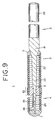
- the guide wire 1 according to the fourth embodiment shown in Fig. 9 is different from the first embodiment only in the position of the distal end 36 of the elongate member 35.
- the elongate member 35 is adapted to be shorter and the distal end 36 of the elongate member 35 is not fixed by the fixing material 7 but is free. Since the distal end 36 of the elongate member 35 is formed as a free end, the flexibility of the guide wire 1 is further improved.
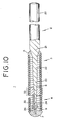
- the guide wire 1 according to the fifth embodiment shown in Fig. 10 is different from the first embodiment only in the position of the distal end 36 of the elongate member 35.
- the elongate member 35 is adapted to be shorter and the distal end 36 of the elongate member 35 is disposed and fixed in the middle of the small diameter section 24.
- the fixing method is not limited in particular.
- a fixing material 9 such as soldering or brazing material, is used.
- Other fixing methods are, for example, welding or bonding with an adhesive material.
- the elongate member 35 can follow the small diameter section 24 easily when the distal end of the guide wire 1 is bent or curved. This improves the capability to follow blood vessels that run and/or branch in a complex manner and prevents the distal end 25 from exposing on the outside of the coil via the gaps formed between the wires as the second coil 4 elongates.
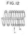
- the guide wire 1 according to the sixth embodiment shown in Fig. 11 is different from the first embodiment in the coil structure of the guide wire. While the coil consists of two coils, i.e., the first coil 3 and the second coil 4, the coil structure of the sixth embodiment consists of a single coil, or the coil 3 alone.
- the elongate member 35 is disposed in the internal space of the distal end of the coil 3.
- the elongate member 35 is made from the same material as that of the coil 3 as an integral part and extends into the inside of the coil 3 after making a U-turn at the distal end of the coil 3.
- Fig. 12 illustrates a state of the elongate member 35 extending from the distal end of the coil 3 as its integral part.
- the elongate member 35 is located substantially in the center of the coil 3.
- the transitional part from the coil 3 to the elongate member 35 resides inside the fixing material 7 and the proximal end of the elongate member 35 is fixed by being embedded inside the fixing material 6.
- the material forming the coil 3 and the elongate member 35 is radiopaque and can be reshaped.
- the elongate member 35 extends as an integral part from the distal end of the coil 3, but it can also be formed to extend as an integral part from the proximal end of the coil 3.
- the flexibility and the bending characteristic of the distal end of the guide wire 1 by properly choosing the combination of the selection of the fixing methods and fixing positions according to the elongate member 35, the second coil 4, and the wire body 2, as well as the selection of the materials, shapes and dimensions according to the composing members such as the wire body 2, the first coil 3, the elongate member 35, and the second coil 4.
- the elongate member 35 is formed on the distal end of the first coil 3 as an integral part, the following modifications 1 through 6 can be applied as well.
- the elongate member 35 is formed integrally on the proximal end of the first coil 3, extends from the proximal end of the first coil 3 toward the distal end direction, and is inserted into the first coil 3 and the second coil 4, which is connected to the first coil 3.
- the elongate member 35 is formed integrally on the proximal end of the second coil 4, extends from the proximal end of the second coil 4 toward the distal end direction, and is inserted into the second coil 4.
- the elongate member 35 is formed integrally on the distal end of the second coil 4, extends from the distal end of the second coil 4 toward the proximal end direction, and is inserted into the second coil 4 or into both the second coil and the first coil 3.
- Modification 4 has two elongate members 35.
- the first elongate member 35 is formed integrally on the proximal end of the first coil 3, extends from the proximal end of the first coil 3 toward the distal end direction, and is inserted into the ins ide of the first coil 3.
- the second elongate member 35 is formed on the proximal end of the second coil 4 integrally, extends from the proximal end of the second coil 4 toward the distal end direction, and is inserted into the inside of the second coil 4.
- Modification 5 has two elongate members 35.
- the first elongate member 35 is formed integrally on the distal end of the first coil 3, extends from the distal end of the first coil 3 toward the distal end direction, and is inserted into the inside of the second coil 4.
- the second elongate member 35 is formed on the proximal end of the second coil 4 integrally, extends from the proximal end of the second coil 4 toward the proximal end direction, and is inserted into the inside of the first coil 3.
- the proximal end of the second elongate member 35 can be disposed in any place along the longitudinal direction either at the first taper section 21, the intermediate section 22, or the second taper section 23.
- Modification 6 has two elongate members 35.
- the first elongate member 35 is formed integrally on the distal end of the first coil 3, extends from the distal end of the first coil 3 toward the distal end direction, and is inserted into the inside of the second coil 4.
- the second elongate member 35 is formed on the distal end of the second coil 4 integrally, extends from the distal end of the second coil 4 toward the proximal end direction, and is inserted into the inside of the second coil 4, or the inside of both the second coil 4 and the first coil 3.
- the location of the distal or proximal end of the elongate member 35 in the abovementioned modifications 1 through 6 is not limited in particular.
- the guide wire according to this invention has an elongate member, which is useful for reshaping the distal end of the guide wire. Therefore, even if the wire body is made of a material that is difficult to give shape thereto, for example, super elasticity alloy, it is possible to secure a sufficient reshape capability at the distal end of the guide wire.
- the elongate member Since the elongate member is formed integrally with the first coil or the second coil, it prevents the elongate member from falling off during reshaping or when using the guide wire. Moreover, it makes it easier to assemble, i.e., manufacture, the guide wire in comparison with a case of forming the elongate member with other material because it uses a lesser number of components.
- the guide wire in accordance with this invention is capable of providing an excellent flexibility to the distal end of the guide wire in addition to the abovementioned excellent reshape capability. This is extremely important as it improves the maneuverability and safety during its insertion into a living body.
- the guide wire according to this invention is quite useful when it is applied to a catheter to be inserted into a body cavity such as a blood vessel, as it makes it possible to provide an optimum treatment corresponding to each medical case.
Landscapes
- Health & Medical Sciences (AREA)
- Life Sciences & Earth Sciences (AREA)
- Biophysics (AREA)
- Pulmonology (AREA)
- Engineering & Computer Science (AREA)
- Anesthesiology (AREA)
- Biomedical Technology (AREA)
- Heart & Thoracic Surgery (AREA)
- Hematology (AREA)
- Animal Behavior & Ethology (AREA)
- General Health & Medical Sciences (AREA)
- Public Health (AREA)
- Veterinary Medicine (AREA)
- Media Introduction/Drainage Providing Device (AREA)
- Valve-Gear Or Valve Arrangements (AREA)
Applications Claiming Priority (3)
| Application Number | Priority Date | Filing Date | Title |
|---|---|---|---|
| JP2002019165A JP4028245B2 (ja) | 2002-01-28 | 2002-01-28 | ガイドワイヤ |
| JP2002019165 | 2002-01-28 | ||
| PCT/JP2003/000791 WO2003063943A1 (en) | 2002-01-28 | 2003-01-28 | Guide wire |
Publications (2)
| Publication Number | Publication Date |
|---|---|
| EP1469901A1 EP1469901A1 (en) | 2004-10-27 |
| EP1469901B1 true EP1469901B1 (en) | 2006-09-06 |
Family
ID=27654158
Family Applications (1)
| Application Number | Title | Priority Date | Filing Date |
|---|---|---|---|
| EP03701901A Expired - Lifetime EP1469901B1 (en) | 2002-01-28 | 2003-01-28 | Guide wire |
Country Status (6)
| Country | Link |
|---|---|
| US (1) | US7252643B2 (zh) |
| EP (1) | EP1469901B1 (zh) |
| JP (1) | JP4028245B2 (zh) |
| AT (1) | ATE338573T1 (zh) |
| DE (1) | DE60308146T2 (zh) |
| WO (1) | WO2003063943A1 (zh) |
Families Citing this family (24)
| Publication number | Priority date | Publication date | Assignee | Title |
|---|---|---|---|---|
| JP4416421B2 (ja) * | 2003-03-18 | 2010-02-17 | テルモ株式会社 | ガイドワイヤおよびその製造方法 |
| JP4677205B2 (ja) * | 2003-07-17 | 2011-04-27 | テルモ株式会社 | ガイドワイヤ |
| US7785273B2 (en) * | 2003-09-22 | 2010-08-31 | Boston Scientific Scimed, Inc. | Guidewire with reinforcing member |
| JP3726266B2 (ja) * | 2003-10-02 | 2005-12-14 | 朝日インテック株式会社 | 医療用ガイドワイヤの先端部構造 |
| US7819887B2 (en) | 2004-11-17 | 2010-10-26 | Rex Medical, L.P. | Rotational thrombectomy wire |
| US20070185415A1 (en) * | 2005-07-07 | 2007-08-09 | Ressemann Thomas V | Steerable guide wire with torsionally stable tip |
| US8267872B2 (en) * | 2005-07-07 | 2012-09-18 | St. Jude Medical, Cardiology Division, Inc. | Steerable guide wire with torsionally stable tip |
| IL181489A0 (en) * | 2007-02-21 | 2007-07-04 | Ovalum Ltd | Deformation of the distal portion of a guidewire |
| US8444577B2 (en) * | 2009-01-05 | 2013-05-21 | Cook Medical Technologies Llc | Medical guide wire |
| GB0902339D0 (en) * | 2009-02-12 | 2009-04-01 | St Georges Healthcare Nhs Trus | Percutaneous guidewire |
| JP2010252938A (ja) * | 2009-04-23 | 2010-11-11 | Hi-Lex Corporation | ガイドワイヤ |
| JP4863321B2 (ja) * | 2009-06-16 | 2012-01-25 | 朝日インテック株式会社 | 医療用ガイドワイヤ |
| JP4993632B2 (ja) | 2009-06-16 | 2012-08-08 | 朝日インテック株式会社 | 医療用ガイドワイヤ |
| US9795406B2 (en) | 2010-05-13 | 2017-10-24 | Rex Medical, L.P. | Rotational thrombectomy wire |
| US8764779B2 (en) | 2010-05-13 | 2014-07-01 | Rex Medical, L.P. | Rotational thrombectomy wire |
| US9023070B2 (en) | 2010-05-13 | 2015-05-05 | Rex Medical, L.P. | Rotational thrombectomy wire coupler |
| US8663259B2 (en) | 2010-05-13 | 2014-03-04 | Rex Medical L.P. | Rotational thrombectomy wire |
| JP5392784B2 (ja) * | 2010-06-17 | 2014-01-22 | 朝日インテック株式会社 | 医療用ガイドワイヤ |
| US8864685B2 (en) * | 2010-10-22 | 2014-10-21 | Cook Medical Technologies Llc | Wire guide having two safety wires |
| JP2012179204A (ja) * | 2011-03-01 | 2012-09-20 | Asahi Intecc Co Ltd | 医療用ガイドワイヤ |
| JP5424499B2 (ja) * | 2011-04-18 | 2014-02-26 | 朝日インテック株式会社 | 医療用ガイドワイヤ |
| US10029076B2 (en) | 2012-02-28 | 2018-07-24 | Covidien Lp | Intravascular guidewire |
| JP5997370B2 (ja) * | 2013-04-01 | 2016-09-28 | テルモ株式会社 | ガイドワイヤ |
| JP6080170B2 (ja) * | 2014-03-20 | 2017-02-15 | 朝日インテック株式会社 | ガイドワイヤ |
Family Cites Families (20)
| Publication number | Priority date | Publication date | Assignee | Title |
|---|---|---|---|---|
| US4538622A (en) | 1983-11-10 | 1985-09-03 | Advanced Cardiovascular Systems, Inc. | Guide wire for catheters |
| US4748986A (en) * | 1985-11-26 | 1988-06-07 | Advanced Cardiovascular Systems, Inc. | Floppy guide wire with opaque tip |
| US4953553A (en) * | 1989-05-11 | 1990-09-04 | Advanced Cardiovascular Systems, Inc. | Pressure monitoring guidewire with a flexible distal portion |
| US5120308A (en) * | 1989-05-03 | 1992-06-09 | Progressive Angioplasty Systems, Inc. | Catheter with high tactile guide wire |
| US5195954A (en) * | 1990-06-26 | 1993-03-23 | Schnepp Pesch Wolfram | Apparatus for the removal of deposits in vessels and organs of animals |
| US5345945A (en) * | 1990-08-29 | 1994-09-13 | Baxter International Inc. | Dual coil guidewire with radiopaque distal tip |
| US5174302A (en) * | 1990-12-04 | 1992-12-29 | Cordis Corporation | Variable radiopacity guidewire with spaced highly radiopaque regions |
| US6165292A (en) | 1990-12-18 | 2000-12-26 | Advanced Cardiovascular Systems, Inc. | Superelastic guiding member |
| US5341818A (en) | 1992-12-22 | 1994-08-30 | Advanced Cardiovascular Systems, Inc. | Guidewire with superelastic distal portion |
| US5605162A (en) | 1991-10-15 | 1997-02-25 | Advanced Cardiovascular Systems, Inc. | Method for using a variable stiffness guidewire |
| US5606981A (en) * | 1994-03-11 | 1997-03-04 | C. R. Bard, Inc. | Catheter guidewire with radiopaque markers |
| ES2148362T3 (es) * | 1995-03-02 | 2000-10-16 | Schneider Europ Gmbh | Metodo para fabricar un alambre guia. |
| US5931819A (en) * | 1996-04-18 | 1999-08-03 | Advanced Cardiovascular Systems, Inc. | Guidewire with a variable stiffness distal portion |
| EP0901392B1 (en) | 1996-05-20 | 2004-03-31 | Medtronic Ave, Inc. | Catheter balloon with an extending core wire |
| US5865768A (en) * | 1996-09-30 | 1999-02-02 | Medtronic, Inc. | Guide wire |
| US5876356A (en) * | 1997-04-02 | 1999-03-02 | Cordis Corporation | Superelastic guidewire with a shapeable tip |
| US5980471A (en) * | 1997-10-10 | 1999-11-09 | Advanced Cardiovascular System, Inc. | Guidewire with tubular connector |
| US6464650B2 (en) * | 1998-12-31 | 2002-10-15 | Advanced Cardiovascular Systems, Inc. | Guidewire with smoothly tapered segment |
| WO2000065987A1 (en) * | 1999-04-30 | 2000-11-09 | Applied Medical Resources Corporation | Guidewire |
| WO2001087412A2 (en) * | 2000-05-17 | 2001-11-22 | Cook Vascular Incorporated | Lead removal apparatus |
-
2002
- 2002-01-28 JP JP2002019165A patent/JP4028245B2/ja not_active Expired - Lifetime
-
2003
- 2003-01-28 US US10/352,101 patent/US7252643B2/en not_active Expired - Lifetime
- 2003-01-28 WO PCT/JP2003/000791 patent/WO2003063943A1/en active IP Right Grant
- 2003-01-28 AT AT03701901T patent/ATE338573T1/de not_active IP Right Cessation
- 2003-01-28 DE DE60308146T patent/DE60308146T2/de not_active Expired - Lifetime
- 2003-01-28 EP EP03701901A patent/EP1469901B1/en not_active Expired - Lifetime
Also Published As
| Publication number | Publication date |
|---|---|
| US20030181828A1 (en) | 2003-09-25 |
| JP2003220144A (ja) | 2003-08-05 |
| DE60308146T2 (de) | 2008-02-28 |
| EP1469901A1 (en) | 2004-10-27 |
| JP4028245B2 (ja) | 2007-12-26 |
| WO2003063943A1 (en) | 2003-08-07 |
| ATE338573T1 (de) | 2006-09-15 |
| US7252643B2 (en) | 2007-08-07 |
| DE60308146D1 (de) | 2006-10-19 |
Similar Documents
| Publication | Publication Date | Title |
|---|---|---|
| EP1469901B1 (en) | Guide wire | |
| EP2417999B1 (en) | Guidewire with bent portion fixed with a fixing member | |
| JP5489983B2 (ja) | ガイドワイヤ | |
| US8708932B2 (en) | Guide wire | |
| EP1651301B1 (en) | Guide wire for a catheter | |
| US7770779B2 (en) | Guide wire | |
| US7722551B2 (en) | Guide wire | |
| US8172774B2 (en) | Guide wire | |
| JP2010029736A (ja) | 人体構造内を進行する医療用具 | |
| JP2008245852A (ja) | ガイドワイヤ | |
| WO2009119387A1 (ja) | ガイドワイヤおよびガイドワイヤの製造方法 | |
| US20150119757A1 (en) | Coil body and guide wire | |
| JP2018079246A (ja) | ガイドワイヤ | |
| US10130796B2 (en) | Guide wire and method for manufacturing a guide wire | |
| US20170120018A1 (en) | Guidewire | |
| US9808604B2 (en) | Guide wire | |
| JP3962652B2 (ja) | ガイドワイヤ | |
| JP2019150317A (ja) | ガイドワイヤ | |
| JP4116944B2 (ja) | ガイドワイヤ | |
| JP2008110266A (ja) | ガイドワイヤ | |
| JP2018187225A (ja) | ガイドワイヤ | |
| IES84007Y1 (en) | A guide wire for use with a catheter | |
| IE20040535U1 (en) | A guide wire for use with a catheter |
Legal Events
| Date | Code | Title | Description |
|---|---|---|---|
| PUAI | Public reference made under article 153(3) epc to a published international application that has entered the european phase |
Free format text: ORIGINAL CODE: 0009012 |
|
| 17P | Request for examination filed |
Effective date: 20030916 |
|
| AK | Designated contracting states |
Kind code of ref document: A1 Designated state(s): AT BE BG CH CY CZ DE DK EE ES FI FR GB GR HU IE IT LI LU MC NL PT SE SI SK TR |
|
| AX | Request for extension of the european patent |
Extension state: AL LT LV MK RO |
|
| GRAP | Despatch of communication of intention to grant a patent |
Free format text: ORIGINAL CODE: EPIDOSNIGR1 |
|
| GRAS | Grant fee paid |
Free format text: ORIGINAL CODE: EPIDOSNIGR3 |
|
| GRAA | (expected) grant |
Free format text: ORIGINAL CODE: 0009210 |
|
| AK | Designated contracting states |
Kind code of ref document: B1 Designated state(s): AT BE BG CH CY CZ DE DK EE ES FI FR GB GR HU IE IT LI LU MC NL PT SE SI SK TR |
|
| PG25 | Lapsed in a contracting state [announced via postgrant information from national office to epo] |
Ref country code: IT Free format text: LAPSE BECAUSE OF FAILURE TO SUBMIT A TRANSLATION OF THE DESCRIPTION OR TO PAY THE FEE WITHIN THE PRESCRIBED TIME-LIMIT;WARNING: LAPSES OF ITALIAN PATENTS WITH EFFECTIVE DATE BEFORE 2007 MAY HAVE OCCURRED AT ANY TIME BEFORE 2007. THE CORRECT EFFECTIVE DATE MAY BE DIFFERENT FROM THE ONE RECORDED. Effective date: 20060906 Ref country code: NL Free format text: LAPSE BECAUSE OF FAILURE TO SUBMIT A TRANSLATION OF THE DESCRIPTION OR TO PAY THE FEE WITHIN THE PRESCRIBED TIME-LIMIT Effective date: 20060906 Ref country code: LI Free format text: LAPSE BECAUSE OF FAILURE TO SUBMIT A TRANSLATION OF THE DESCRIPTION OR TO PAY THE FEE WITHIN THE PRESCRIBED TIME-LIMIT Effective date: 20060906 Ref country code: FI Free format text: LAPSE BECAUSE OF FAILURE TO SUBMIT A TRANSLATION OF THE DESCRIPTION OR TO PAY THE FEE WITHIN THE PRESCRIBED TIME-LIMIT Effective date: 20060906 Ref country code: SI Free format text: LAPSE BECAUSE OF FAILURE TO SUBMIT A TRANSLATION OF THE DESCRIPTION OR TO PAY THE FEE WITHIN THE PRESCRIBED TIME-LIMIT Effective date: 20060906 Ref country code: CH Free format text: LAPSE BECAUSE OF FAILURE TO SUBMIT A TRANSLATION OF THE DESCRIPTION OR TO PAY THE FEE WITHIN THE PRESCRIBED TIME-LIMIT Effective date: 20060906 Ref country code: BE Free format text: LAPSE BECAUSE OF FAILURE TO SUBMIT A TRANSLATION OF THE DESCRIPTION OR TO PAY THE FEE WITHIN THE PRESCRIBED TIME-LIMIT Effective date: 20060906 Ref country code: CZ Free format text: LAPSE BECAUSE OF FAILURE TO SUBMIT A TRANSLATION OF THE DESCRIPTION OR TO PAY THE FEE WITHIN THE PRESCRIBED TIME-LIMIT Effective date: 20060906 Ref country code: AT Free format text: LAPSE BECAUSE OF FAILURE TO SUBMIT A TRANSLATION OF THE DESCRIPTION OR TO PAY THE FEE WITHIN THE PRESCRIBED TIME-LIMIT Effective date: 20060906 Ref country code: SK Free format text: LAPSE BECAUSE OF FAILURE TO SUBMIT A TRANSLATION OF THE DESCRIPTION OR TO PAY THE FEE WITHIN THE PRESCRIBED TIME-LIMIT Effective date: 20060906 |
|
| REG | Reference to a national code |
Ref country code: GB Ref legal event code: FG4D |
|
| REG | Reference to a national code |
Ref country code: CH Ref legal event code: EP |
|
| REG | Reference to a national code |
Ref country code: IE Ref legal event code: FG4D |
|
| REF | Corresponds to: |
Ref document number: 60308146 Country of ref document: DE Date of ref document: 20061019 Kind code of ref document: P |
|
| PG25 | Lapsed in a contracting state [announced via postgrant information from national office to epo] |
Ref country code: BG Free format text: LAPSE BECAUSE OF FAILURE TO SUBMIT A TRANSLATION OF THE DESCRIPTION OR TO PAY THE FEE WITHIN THE PRESCRIBED TIME-LIMIT Effective date: 20061206 Ref country code: DK Free format text: LAPSE BECAUSE OF FAILURE TO SUBMIT A TRANSLATION OF THE DESCRIPTION OR TO PAY THE FEE WITHIN THE PRESCRIBED TIME-LIMIT Effective date: 20061206 Ref country code: SE Free format text: LAPSE BECAUSE OF FAILURE TO SUBMIT A TRANSLATION OF THE DESCRIPTION OR TO PAY THE FEE WITHIN THE PRESCRIBED TIME-LIMIT Effective date: 20061206 |
|
| PG25 | Lapsed in a contracting state [announced via postgrant information from national office to epo] |
Ref country code: ES Free format text: LAPSE BECAUSE OF FAILURE TO SUBMIT A TRANSLATION OF THE DESCRIPTION OR TO PAY THE FEE WITHIN THE PRESCRIBED TIME-LIMIT Effective date: 20061217 |
|
| PG25 | Lapsed in a contracting state [announced via postgrant information from national office to epo] |
Ref country code: MC Free format text: LAPSE BECAUSE OF NON-PAYMENT OF DUE FEES Effective date: 20070131 |
|
| ET | Fr: translation filed | ||
| PG25 | Lapsed in a contracting state [announced via postgrant information from national office to epo] |
Ref country code: PT Free format text: LAPSE BECAUSE OF FAILURE TO SUBMIT A TRANSLATION OF THE DESCRIPTION OR TO PAY THE FEE WITHIN THE PRESCRIBED TIME-LIMIT Effective date: 20070219 |
|
| NLV1 | Nl: lapsed or annulled due to failure to fulfill the requirements of art. 29p and 29m of the patents act | ||
| REG | Reference to a national code |
Ref country code: CH Ref legal event code: PL |
|
| PLBE | No opposition filed within time limit |
Free format text: ORIGINAL CODE: 0009261 |
|
| STAA | Information on the status of an ep patent application or granted ep patent |
Free format text: STATUS: NO OPPOSITION FILED WITHIN TIME LIMIT |
|
| 26N | No opposition filed |
Effective date: 20070607 |
|
| PG25 | Lapsed in a contracting state [announced via postgrant information from national office to epo] |
Ref country code: IE Free format text: LAPSE BECAUSE OF NON-PAYMENT OF DUE FEES Effective date: 20070129 |
|
| PG25 | Lapsed in a contracting state [announced via postgrant information from national office to epo] |
Ref country code: GR Free format text: LAPSE BECAUSE OF FAILURE TO SUBMIT A TRANSLATION OF THE DESCRIPTION OR TO PAY THE FEE WITHIN THE PRESCRIBED TIME-LIMIT Effective date: 20061207 |
|
| PG25 | Lapsed in a contracting state [announced via postgrant information from national office to epo] |
Ref country code: EE Free format text: LAPSE BECAUSE OF FAILURE TO SUBMIT A TRANSLATION OF THE DESCRIPTION OR TO PAY THE FEE WITHIN THE PRESCRIBED TIME-LIMIT Effective date: 20060906 |
|
| PG25 | Lapsed in a contracting state [announced via postgrant information from national office to epo] |
Ref country code: LU Free format text: LAPSE BECAUSE OF NON-PAYMENT OF DUE FEES Effective date: 20070128 Ref country code: CY Free format text: LAPSE BECAUSE OF FAILURE TO SUBMIT A TRANSLATION OF THE DESCRIPTION OR TO PAY THE FEE WITHIN THE PRESCRIBED TIME-LIMIT Effective date: 20060906 |
|
| PG25 | Lapsed in a contracting state [announced via postgrant information from national office to epo] |
Ref country code: TR Free format text: LAPSE BECAUSE OF FAILURE TO SUBMIT A TRANSLATION OF THE DESCRIPTION OR TO PAY THE FEE WITHIN THE PRESCRIBED TIME-LIMIT Effective date: 20060906 Ref country code: HU Free format text: LAPSE BECAUSE OF FAILURE TO SUBMIT A TRANSLATION OF THE DESCRIPTION OR TO PAY THE FEE WITHIN THE PRESCRIBED TIME-LIMIT Effective date: 20070307 |
|
| REG | Reference to a national code |
Ref country code: FR Ref legal event code: PLFP Year of fee payment: 14 |
|
| REG | Reference to a national code |
Ref country code: FR Ref legal event code: PLFP Year of fee payment: 15 |
|
| REG | Reference to a national code |
Ref country code: FR Ref legal event code: PLFP Year of fee payment: 16 |
|
| PGFP | Annual fee paid to national office [announced via postgrant information from national office to epo] |
Ref country code: FR Payment date: 20181213 Year of fee payment: 17 |
|
| PGFP | Annual fee paid to national office [announced via postgrant information from national office to epo] |
Ref country code: GB Payment date: 20190123 Year of fee payment: 17 Ref country code: DE Payment date: 20190115 Year of fee payment: 17 |
|
| REG | Reference to a national code |
Ref country code: DE Ref legal event code: R119 Ref document number: 60308146 Country of ref document: DE |
|
| GBPC | Gb: european patent ceased through non-payment of renewal fee |
Effective date: 20200128 |
|
| PG25 | Lapsed in a contracting state [announced via postgrant information from national office to epo] |
Ref country code: GB Free format text: LAPSE BECAUSE OF NON-PAYMENT OF DUE FEES Effective date: 20200128 Ref country code: FR Free format text: LAPSE BECAUSE OF NON-PAYMENT OF DUE FEES Effective date: 20200131 Ref country code: DE Free format text: LAPSE BECAUSE OF NON-PAYMENT OF DUE FEES Effective date: 20200801 |