EP1468883A1 - Rétracteur de ceinture de sécurité - Google Patents
Rétracteur de ceinture de sécurité Download PDFInfo
- Publication number
- EP1468883A1 EP1468883A1 EP04008987A EP04008987A EP1468883A1 EP 1468883 A1 EP1468883 A1 EP 1468883A1 EP 04008987 A EP04008987 A EP 04008987A EP 04008987 A EP04008987 A EP 04008987A EP 1468883 A1 EP1468883 A1 EP 1468883A1
- Authority
- EP
- European Patent Office
- Prior art keywords
- seat belt
- spool
- load
- strip
- energy absorbing
- Prior art date
- Legal status (The legal status is an assumption and is not a legal conclusion. Google has not performed a legal analysis and makes no representation as to the accuracy of the status listed.)
- Withdrawn
Links
Images


Classifications
-
- B—PERFORMING OPERATIONS; TRANSPORTING
- B60—VEHICLES IN GENERAL
- B60R—VEHICLES, VEHICLE FITTINGS, OR VEHICLE PARTS, NOT OTHERWISE PROVIDED FOR
- B60R22/00—Safety belts or body harnesses in vehicles
- B60R22/34—Belt retractors, e.g. reels
- B60R22/341—Belt retractors, e.g. reels comprising energy-absorbing means
- B60R22/3413—Belt retractors, e.g. reels comprising energy-absorbing means operating between belt reel and retractor frame
-
- B—PERFORMING OPERATIONS; TRANSPORTING
- B60—VEHICLES IN GENERAL
- B60R—VEHICLES, VEHICLE FITTINGS, OR VEHICLE PARTS, NOT OTHERWISE PROVIDED FOR
- B60R22/00—Safety belts or body harnesses in vehicles
- B60R22/28—Safety belts or body harnesses in vehicles incorporating energy-absorbing devices
- B60R2022/286—Safety belts or body harnesses in vehicles incorporating energy-absorbing devices using deformation of material
- B60R2022/287—Safety belts or body harnesses in vehicles incorporating energy-absorbing devices using deformation of material of torsion rods or tubes
-
- B—PERFORMING OPERATIONS; TRANSPORTING
- B60—VEHICLES IN GENERAL
- B60R—VEHICLES, VEHICLE FITTINGS, OR VEHICLE PARTS, NOT OTHERWISE PROVIDED FOR
- B60R22/00—Safety belts or body harnesses in vehicles
- B60R22/34—Belt retractors, e.g. reels
- B60R22/46—Reels with means to tension the belt in an emergency by forced winding up
- B60R22/4676—Reels with means to tension the belt in an emergency by forced winding up comprising energy-absorbing means operating between belt reel and retractor frame
Definitions
- the present invention relates to a seat belt retractor for retracting a seat belt so that it can be withdrawn, and a seat belt device equipped with this seat belt retractor. More specifically, the present invention relates to a seat belt retractor including an energy absorbing mechanism (hereinafter referred to as "EA mechanism") for absorbing the energy of impact made by the seat belt on a wearer displaced due to inertia in an emergency, such as a collision, causing a large deceleration, and a seat belt device equipped with this seat belt retractor.
- EA mechanism energy absorbing mechanism
- Known seat belt devices installed on vehicles include at least a seat belt retractor for retracting a seat belt, a seat belt which is withdrawn from the seat belt retractor and whose end is connected to an auto body, a buckle fixed to the auto body, and a tongue which is slidably fitted to the seat belt and which can engage with the buckle.
- the seat belt When the seat belt is not worn, the seat belt is wound in a spool of the seat belt retractor. After being seated, an occupant withdraws the seat belt from the seat belt retractor to a predetermined length and then engages a tongue with a buckle. The seat belt is thus worn by the occupant.
- the portion between the tongue and the seat belt retractor is worn over the shoulder and chest as a shoulder belt, and the portion between the tongue and a connection with the auto body is worn round the waist as a lap belt.
- a locking mechanism operates to prevent the spool from rotating in the direction of unwinding in the emergency described above, thereby preventing the seat belt from being withdrawn.
- This enables the shoulder belt to restrain the shoulder and chest of the occupant and the lap belt to restrain the waist of the occupant.
- the seat belt device thus prevents the occupant from being thrown forward to protect the occupant.
- a seat belt retractor provided with a torsion bar has been developed.
- the torsion bar absorbs the impact energy to restrict the load applied to the seat belt.
- FIG. 6 is a vertical sectional view showing an example of a seat belt retractor including such a torsion bar.
- Reference numeral 1 represents a seat belt retractor.
- Reference numeral 2 represents a U-shaped frame.
- Reference numeral 3 represents a seat belt.
- Reference numeral 4 represents a spool, which is supported rotatably between both side walls of the U-shaped frame 2, and which is for winding the seat belt 3.
- Reference numeral 5 represents a deceleration sensing means, which is activated when it senses a large deceleration that occurs in the above-described emergency.
- Reference numeral 6 represents a locking mechanism, which is activated by the deceleration sensing means 5 to prevent the spool 4 from rotating at least in the direction of unwinding the seat belt.
- Reference numeral 7 represents a torsion bar, which is inserted into the center of the spool 4, and which connects the spool 4 and the locking mechanism 6 rotatably.
- Reference numeral 8 represents a spring means, which constantly urges the spool 4 in the direction of winding the seat belt by the spring force of a spiral spring 9 via a bush 10.
- Reference numeral 11 represents a pre-tensioner, which is activated in the above-described emergency to produce a belt winding torque.
- Reference numeral 12 represents a bush, which transmits a seat belt winding torque of the pre-tensioner 11 to the spool 4.
- the locking mechanism 6 includes a locking base 14 (corresponding to a locking member of the present invention), which is supported by a first torque transmitting portion 17 of the torsion bar 7 so as to rotate together therewith, and which holds a pawl 13 rockably.
- the locking mechanism 6 further includes a locking gear 6a.
- the locking gear 6a rotates together with the torsion bar 7 during normal times and stops in an emergency by operation of the deceleration sensing means 5 to make a rotational difference relative to the torsion bar 7, thereby engaging the pawl 13 with an internal teeth 19 in the side wall of the frame 2 and preventing the locking base 14 and the spool 4 from rotating in the direction of unwinding the seat belt.
- a ring-shaped relative rotation locking member 15 is disposed between the spool 4 and the shaft portion 14a of the locking base 14.
- This relative rotation locking member 15 has a female thread 15a on the inner peripheral surface.
- the shaft portion 14a of the locking base 14 has a male thread 14c.
- the relative rotation locking member 15 is screwed on the shaft portion 14a of the locking base 14, and fitted into the axial hole of the spool 4 so that it is not capable of rotating relatively and capable of moving axially.
- the spool 4 Due to the spring force of the spring means 8, the spool 4 is urged constantly in the direction of winding the seat belt via the bush 10, torsion bar 7, the second torque transmitting portion 18 of the torsion bar 7, and the bush 12.
- the belt-winding torque produced in the pre-tensioner 11 is transmitted to the spool 4 via the bush 12. In this way, the spool 4 winds the seat belt to a predetermined length.
- the seat belt 3 when the seat belt is not worn, the seat belt 3 is retracted completely by the urging force of the spring means 8.
- the spool 4 rotates in the direction of unwinding the seat belt, and the seat belt 3 is withdrawn smoothly.
- a tongue (not shown), which is slidably fitted to the seat belt 3
- a buckle (not shown)
- the portion of the seat belt 3 that has been withdrawn to excess is wound by the spool 4 by the urging force of the spring means 8. In this way, the seat belt 3 is fitted to an occupant without inflicting a feeling of pressure.
- seat belt winding torque produced by the pre-tensioner 11 is transmitted to the spool 4.
- the spool 4 winds the seat belt 3 to a predetermined length to protect the occupant quickly.
- the deceleration sensing means 5 is activated by the large deceleration occurring in the emergency, and then the locking mechanism 6 is activated.
- the lock gear 6a is prevented from rotating in the direction of unwinding the seat belt.
- the pawl 13 of the locking mechanism 6 is turned to be engaged with the internal teeth 19 in the side wall of the frame 2.
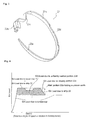
- EA load The characteristics of the counter load (hereinafter referred to as "EA load" generated by the EA mechanism is shown in FIG. 4. That is to say, the EA load generated by the torsion bar 7 increases gradually as the stroke (degree) of rotation of the spool 4 relative to the locking base 14 increases, then becomes a fixed value.
- the relative rotation locking member 15 moves axially towards the right in FIG. 6.
- the relative rotation locking member 15 thus stops rotating relative to the locking base 14.
- the spool 4 also stops rotating relative to the locking base 14. That is to say, the rotation of the spool 4 in the direction of unwinding the seat belt is locked.
- the seat belt 3 is prevented from being withdrawn.
- the seat belt 3 prevents displacement of the occupants caused by inertia to protect the occupant.
- the locking base 14 of the locking mechanism 6 of this known seat belt retractor 1 When the seat belt is withdrawn suddenly, the locking base 14 of the locking mechanism 6 of this known seat belt retractor 1 also rotates in the direction of unwinding the seat belt relative to the locking gear 6a.
- the pawl 13 of the locking mechanism 6 engages with the inner teeth 19 of the side wall of the frame 2, and the locking base 14 is prevented from rotating. Therefore, the spool 4 is prevented from rotating in the direction of unwinding, via the torsion bar 7. The seat belt is thus prevented from being withdrawn.
- this known torsion bar can absorb the impact energy to the occupant in an emergency, it is desirable to absorb this impact energy to the occupant as effectively and appropriately as possible.
- Japanese Unexamined Patent Application Publication No. 2002-53007 discloses an impact energy absorber disposed between a spool and a locking base, the absorber including a wire and engaging pins.
- the spool rotates relative to the locking base, the wire is deformed by the engaging pins, thereby absorbing the impact energy.
- Japanese Unexamined Patent Application Publication No. 2000-85527 discloses an impact energy absorber including: a carrier fixed to one end of a torsion rod so as to rotate together with the end; a housing having a curved guide groove curved; and a band-shaped pulling means one end of which is connected to the carrier and which is fitted in the guide groove.
- the carrier rotates relative to the housing, the pulling means is pulled and forced through the guide groove.
- the pulling means is deformed along the guide groove, thereby absorbing the impact energy.
- the energy absorbing means disclosed in Japanese Unexamined Patent Application Publication No. 2000-85527 absorbs energy by deforming a cylindrical portion plastically toward the inside. However, it is difficult to deform the cylindrical portion plastically toward the inside evenly. Therefore, it is difficult to have the desired energy absorbing effect stably.
- the energy absorbing means is composed of a cylindrical portion and a flange portion and it is necessary to form a cut-off portion in the cylindrical portion, the energy absorbing means is complex in structure, comparatively difficult to process, and expensive.
- the cylindrical portion makes the axial size of the retractor large.
- the seat belt retractor includes a spool for winding a seat belt, a locking mechanism having a locking member that rotates together with the spool during normal times and that is prevented from rotating in the direction of unwinding the seat belt in an emergency, and an energy absorbing mechanism provided between the spool and the locking member and absorbing the energy of impact made on an occupant when the spool rotates in the direction of unwinding the seat belt relative to the locking member in an emergency.
- the energy absorbing mechanism includes a strip energy absorbing member provided in one of the spool and the locking member, and deforming means provided in the other of the spool and the locking member for deforming the energy absorbing member. The width of the strip energy absorbing member varies from part to part.
- the deforming means deforms the energy absorbing member that moves with the rotation of the spool when the spool rotates in the direction of unwinding the seat belt relative to the locking member that is prevented from rotating in the direction of unwinding the seat belt in an emergency, thereby restricting the load applied to the seat belt and absorbing the impact energy, and the amount of the absorbed impact energy varies from stage to stage.
- the deforming means is an arc groove and the strip energy absorbing member is forced through the groove to be deformed.
- the spool and the locking member are connected with a torsion bar that twists when the spool and the locking member rotate relative to each other.
- a seat belt device preferably includes a seat belt retractor according to the invention, a seat belt which is withdrawn from the seat belt retractor and whose end is connected to an auto body, a buckle fixed to the auto body, and a tongue which is slidably fitted to the seat belt and which can engage with the buckle.
- EA load due to deformation of the energy absorbing member is variable according to the width of the member. Therefore, EA load is adjustable to, for example, the type of automobile. By adjusting an EA load to, for example, the type of automobile, the energy of impact made on an occupant is absorbed more effectively and more appropriately.
- the energy absorbing member is formed of a strip plate, the energy absorbing member is deformed continuously. Therefore, despite simple structure, the energy absorbing effect of the energy absorbing member is more stable.
- the energy absorbing mechanism is a simple strip shape, it is easily assembled and is produced at a low cost.
- EA load is flexibly adjustable, and the energy of impact made on an occupant is absorbed more effectively and more appropriately.
- the seat belt device according to the invention is equipped with a seat belt retractor according to the invention, thereby absorbing the energy of impact made on the occupant effectively, and restraining and protecting the occupant appropriately.
- FIG. 1 shows a first embodiment of a seat belt retractor of the present invention.
- FIG. 1 (a) is a sectional view showing a spool, a torsion bar, and a locking base. These elements correspond to the spool, torsion bar, and locking base of the known seat belt retractor shown in FIG. 6.
- FIG. 1 (b) is a sectional view taken along line IB-IB of FIG. 1 (a) and schematically shows an energy absorbing mechanism included in the seat belt retractor of the first embodiment.
- FIG. 2 is an exploded perspective view of the portion shown in FIG. 1 (a).
- the seat belt retractor 1 of the first embodiment includes a torsion bar 7 as in the known seat belt retractor shown in FIG. 6, and further includes an energy absorbing mechanism 20 provided between a spool 4 and a locking base 14.
- the energy absorbing mechanism 20 is provided with energy absorbing means for restricting the load applied to the seat belt in an emergency and for absorbing the impact energy applied to the occupant.
- the energy absorbing mechanism 20 includes a ring guide plate 21 and a strip 22 for absorbing energy.
- the guide plate 21 is disposed between the right side of the spool 4 and the left side of the flange 14b of the locking base 14.
- the strip 22 is formed of a long plate such as a stainless steel plate and is substantially ring-shaped.
- the guide plate 21 has a flange 21a around the periphery and a predetermined number (two in FIG. 3) of engaging recesses 21b and 21c at a side facing the flange 14b.
- the guide plate 21 further has a substantially arc-shaped guide groove 21d for guiding the strip 22 at the other side facing the spool 4.
- the width of the guide groove 21d is larger than the thickness of the strip 22.
- the flange 14b of the locking base 14, at a side facing the guide plate 21, has engaging projections 14d (one of them is not shown) that correspond to the engaging recesses 21b and 21c and that can be fitted into them so that the locking base 14 can be fixed to the guide plate 21.
- the engaging projections 14d are fitted into the recesses 21b and 21c, and the locking base 14 is fixed to the guide plate 21 so as to rotate together with the locking base 14.
- the spool 4 has an engaging notch 4b on the rim of the right flange 4a.
- a main portion 22a of the strip 22 has a uniform width.
- the strip 22 has a U-shaped engaging portion 22b which can engage with the engaging notch 4b of the spool 4 at one end.
- the engaging portion 22b is engaged with the engaging notch 4b of the spool 4.
- the strip 22 has an initially deformed portion 22c between the engaging portion 22b and the main portion 22a. As shown in FIG. 1 (b), the initially deformed portion 22c is shaped so as to be fitted in the guide groove 21d.
- the strip 22 has a uniformly narrow portion 22d whose width is uniform and narrower than that of the main portion 22a between the initially deformed portion 22c and an end opposite to the engaging portion 22a.
- the strip 22 has a sloping portion 22e whose width is narrower than that of the main portion 22a and decreases linearly or nonlinearly (linearly in FIG. 3) at the end opposite to the engaging portion 22b.
- the initially deformed portion 22c of the strip 22 is fitted into the guide groove 21d as shown in FIG. 1 (b), so that the strip 22 is fitted to the guide plate 21.
- the engaging portion 22b is engaged with the engaging notch 4b of the spool 4.
- the spool 4, the locking base 14, the guide plate 21, and the strip 22 are assembled.
- the strip 22 except the engaging portion 22b and the initially deformed portion 22c fitted in the guide groove 21d is wound around the main body (except the flange 21a) of the guide plate 21.
- the flange 21a prevents the strip 22 from moving toward the locking base 14 to come off the main body of the guide plate 21.
- the seat belt retractor 1 of the first embodiment is included in a seat belt device (not shown).
- this seat belt device includes at least a seat belt which is withdrawn from the seat belt retractor and whose end is connected to the auto body, a buckle fixed to the auto body, and a tongue which is slidably fitted to the seat belt and which can engage with the buckle.
- the spool 4 and locking base 14 both start to rotate in the direction of unwinding the seat belt, in an emergency, due to the load from the seat belt withdrawn due to inertial movement of the occupant, as in the known retractor 1 described above.
- the locking mechanism 6 is activated and it immediately locks the locking base 14, thereby preventing the locking base 14 from rotating in the direction of unwinding the seat belt.
- the force in the direction of unwinding the seat belt is applied to the spool 4 from the seat belt 3.
- the spool 4 starts to rotate in the direction of unwinding the seat belt relative to the locking base 14.
- the torsion bar 7 is twisted as in the case of the retractor shown in FIG. 6.
- the spool 4 and the relative rotation locking member 15 rotate in the direction of unwinding the seat belt, relative to the locking base 14.
- the impact energy is absorbed by twist-deformation of the torsion bar 7, and EA load is generated.
- the load applied to the seat belt 3 is counteracted by this EA load.
- the spool 4 rotates in the direction of unwinding the seat belt, and the engaging portion 22b rotates in the same direction. Due to rotation of the spool 4, the strip 22 is pulled in the same direction via the engaging portion 22b.
- the initially deformed portion 22c moves in the direction of exiting the guide groove 21d.
- the initially deformed portion 22c is deformed by the guide groove 21d along the guide groove 21d. Due to deformation of the initially deformed portion 22c by the guide groove 21d, deformation resistance (bending resistance) occurs, and sliding resistance occurs between the initially deformed portion 22c and the guide groove 21d. Due to bending resistance and sliding resistance, impact energy is absorbed, and EA load is generated. The load applied to the seat belt 3 is counteracted by this EA load.
- the main portion 22a (the side opposite from the engaging portion 22b) enters and passes through the guide groove 21d. Due to passing of the main portion 22a through the guide groove 21d, the strip 22 is deformed continuously.
- the uniformly narrow portion 22d enters and passes through the guide groove 21d.
- the uniformly narrow portion 22d is deformed continuously. Since the width of the uniformly narrow portion 22d is narrower than that of the main portion 22a, the bending resistance and sliding resistance are smaller. Due to the smaller resistance, the EA load is smaller than that when the main portion 22a passes through the guide groove 21d.
- the main portion 22a enters and passes through the guide groove 21d, thereby generating EA load.
- the amount of EA load returns to the former amount.
- the sloping portion 22e enters and passes through the guide groove 21d.
- the sloping portion 22e is deformed continuously. Since the width of the sloping portion 22e decreases continuously, the bending resistance and sliding resistance decrease continuously. Due to the continuously decreasing resistance, EA load decreases continuously. When the width of the sloping portion 22e decreases linearly, the EA load continuously decreases linearly. When the width of the sloping portion 22e decreases nonlinearly, the EA load continuously decreases nonlinearly.
- the spool 4 rotates almost 360 degrees relative to the locking base 14, while the strip 22 passes through the guide groove 21d. Then, impact energy absorption due to deformation of the strip 22 is stopped. Since only the impact energy absorption due to twist-deformation of the torsion bar 7 is performed, only the EA load due to twist-deformation of the torsion bar 7 is generated. Therefore, the EA load due to deformation of the strip 22 is as shown in FIG. 4.
- the relative rotation locking member 15 When the relative rotation locking member 15 is prevented from moving axially to the right, the relative rotation locking member 15 is locked and the spool 4 is prevented from rotating relative to the locking base 14. That is to say, the spool 4 is prevented from rotating in the direction of unwinding the seat belt, and the seat belt 3 is prevented from being withdrawn. The occupant is thus prevented by the seat belt 3 from moving inertially to be protected.
- the strip 22 is not pulled out due to slight looseness in fitting of the strip 22, and only the small EA load due to twist-deformation of the torsion bar 7 is generated. Then, the strip 22 is immediately tightened and is pulled out. Therefore, the EA load due to deformation of the strip 22 is generated.
- the EA load due to deformation of the strip 22 is variable according to the width of the strip 22, that is to say, the main portion 22a, the uniformly narrow portion 22d, and the sloping portion 22e. Therefore, EA load can be adjusted to, for example, the type of automobile. More specifically, the energy of impact made on the occupant can be absorbed more effectively and more appropriately according to the type of automobile by determining the following: whether to use the uniformly narrow portion 22d or the sloping portion 22e alone, or to use them together; the position, width and length of the uniformly narrow portion 22d; and the position and inclination of the sloping portion 22e. (When the uniformly narrow portion 22d and the sloping portion 22e are used together, they may be separated or adjoined. The order in which they are provided is optional.)
- the guide plate 21 has a simple ring shape, and the strip 22 is formed of a long plate. In addition, the strip 22 passes through the guide groove 21d continuously and it is deformed continuously. Therefore, despite simple structure, the energy absorbing effect of the guide plate 21 is more stable.
- the energy absorbing mechanism 20 Since the guide plate 21 has a simple ring shape and is fitted axially, it is easy to fit the guide plate 21 to the locking base 14 and then to fit the locking base 14, together with the guide plate 21, to the spool 4. Therefore, the energy absorbing mechanism 20 has a simple structure and can be produced at a low cost.
- a seat belt device equipped with the seat belt retractor 1 of the first embodiment can absorb the energy of impact made on the occupant effectively, and can restrain and protect the occupant appropriately.
- a uniformly wide portion whose width is wider than that of the main portion 23a, and a sloping portion whose width increases gradually may be formed in the strip 22.
- the strip 22 may be disposed in the locking base 14, and the guide plate 21 may be disposed in the spool 4.
- a normal drive shaft instead of the torsion bar 7, a normal drive shaft may be used.
- FIGS. 5 (a) and 5 (b) show a second embodiment of the present invention.
- FIG. 5 (a) is a sectional view similar to FIG. 1 (b).
- FIG. 5 (b) is a perspective view of a strip of the second embodiment.
- the same reference numerals will be used to designate the same elements as those of the first embodiment, so that the description will be omitted.
- the guide groove 21d of the guide plate 21 is formed in an arc in the first embodiment
- the guide groove 21d of the guide plate 21 includes a circular groove 21d 1 and a radial groove 21d 2 (formed in the outer circular portion 22f forming the circular groove 21d 1 ).
- an engaging portion 22b of the strip 22 has a U shape when viewed from the side (when viewed in the axial direction of the spool to which the strip 22 is fitted).
- the strip 22 is rubbed with and deformed by the edge of the outer circular portion 22f forming the circular groove 21d 1 .
- EA load due to deformation of the energy absorbing member is variable according to the width of the member. Therefore, EA load is adjustable to, for example, the type of automobile. By adjusting an EA load to, for example, the type of automobile, the energy of impact made on an occupant is absorbed more effectively and more appropriately.
- the energy absorbing member is formed of a strip plate, the energy absorbing member is deformed continuously. Therefore, despite simple structure, the energy absorbing effect of the energy absorbing member is more stable. Since the energy absorbing mechanism is a simple strip shape, it is easily assembled and is produced at a low cost.
- the seat belt retractor comprises the torsion bar 7, a comparatively large EA load consisting of an EA load due to twist-deformation of the torsion bar 7 and another EA load due to deformation of the strip 22, and a comparatively small EA load consisting of only the EA load due to twist-deformation of the torsion bar 7 are generated. Therefore, EA load is flexibly adjustable, and the energy of impact made on an occupant is absorbed more effectively and more appropriately.
- a belt device equipped with a seat belt retractor as described above thereby effectively absorbs the energy of impact made on the occupant, and restrains and protects the occupant appropriately.
Landscapes
- Engineering & Computer Science (AREA)
- Mechanical Engineering (AREA)
- Automotive Seat Belt Assembly (AREA)
Applications Claiming Priority (6)
| Application Number | Priority Date | Filing Date | Title |
|---|---|---|---|
| JP2003110068A JP2004314744A (ja) | 2003-04-15 | 2003-04-15 | シートベルトリトラクタおよびこれを備えたシートベルト装置 |
| JP2003110068 | 2003-04-15 | ||
| JP2003283373A JP4404335B2 (ja) | 2003-07-31 | 2003-07-31 | シートベルトのリトラクター装置及びシートベルト装置 |
| JP2003283373 | 2003-07-31 | ||
| JP2003414607A JP2005170266A (ja) | 2003-12-12 | 2003-12-12 | シートベルトのリトラクター装置 |
| JP2003414607 | 2003-12-12 |
Publications (1)
| Publication Number | Publication Date |
|---|---|
| EP1468883A1 true EP1468883A1 (fr) | 2004-10-20 |
Family
ID=32912847
Family Applications (3)
| Application Number | Title | Priority Date | Filing Date |
|---|---|---|---|
| EP12003335.2A Withdrawn EP2591956A2 (fr) | 2003-04-15 | 2004-04-15 | Rétracteur de ceinture de sécurité |
| EP04008987A Withdrawn EP1468883A1 (fr) | 2003-04-15 | 2004-04-15 | Rétracteur de ceinture de sécurité |
| EP04008985.6A Expired - Fee Related EP1468882B1 (fr) | 2003-04-15 | 2004-04-15 | Rétracteur de ceinture de sécurité |
Family Applications Before (1)
| Application Number | Title | Priority Date | Filing Date |
|---|---|---|---|
| EP12003335.2A Withdrawn EP2591956A2 (fr) | 2003-04-15 | 2004-04-15 | Rétracteur de ceinture de sécurité |
Family Applications After (1)
| Application Number | Title | Priority Date | Filing Date |
|---|---|---|---|
| EP04008985.6A Expired - Fee Related EP1468882B1 (fr) | 2003-04-15 | 2004-04-15 | Rétracteur de ceinture de sécurité |
Country Status (3)
| Country | Link |
|---|---|
| US (1) | US7152824B2 (fr) |
| EP (3) | EP2591956A2 (fr) |
| CN (1) | CN100534837C (fr) |
Cited By (5)
| Publication number | Priority date | Publication date | Assignee | Title |
|---|---|---|---|---|
| EP1619091A1 (fr) * | 2004-07-20 | 2006-01-25 | Key Safety Systems, Inc. | Rétracteur |
| WO2009095050A1 (fr) * | 2008-01-31 | 2009-08-06 | Autoliv Development Ab | Enrouleur de ceinture de sécurité autobloquant |
| DE102014210397A1 (de) * | 2014-06-03 | 2015-12-03 | Autoliv Development Ab | Gurtaufroller für eine Sicherheitsgurteinrichtung eines Kraftfahrzeugs mit einer rotatorischen Straffvorrichtung und einer Kraftbegrenzungseinrichtung |
| WO2015197540A3 (fr) * | 2014-06-23 | 2016-02-25 | Autoliv Development Ab | Enrouleur de ceinture équipé d'un dispositif de limitation de force |
| EP3098118A3 (fr) * | 2015-05-27 | 2016-12-07 | Kabushiki Kaisha Tokai Rika Denki Seisakusho | Dispositif de tension de sangle |
Families Citing this family (30)
| Publication number | Priority date | Publication date | Assignee | Title |
|---|---|---|---|---|
| US7392957B2 (en) | 2003-04-15 | 2008-07-01 | Takata Corporation | Seatbelt retractor system and seatbelt system |
| US20060022078A1 (en) * | 2004-07-28 | 2006-02-02 | Takata Corporation | Seatbelt retractor and seatbelt system |
| US7370822B2 (en) * | 2004-07-28 | 2008-05-13 | Takata Corporation | Seatbelt retractor having multi-level load-limit setting devices |
| JP4632302B2 (ja) * | 2005-03-22 | 2011-02-16 | タカタ株式会社 | シートベルトリトラクタおよびこれを備えたシートベルト装置 |
| JP2006306142A (ja) * | 2005-04-26 | 2006-11-09 | Takata Corp | シートベルトリトラクタおよびこれを備えているシートベルト装置 |
| DE102005026885B4 (de) * | 2005-06-10 | 2015-01-08 | Trw Automotive Gmbh | Kraftbegrenzer für einen Fahrzeug-Sicherheitsgurt |
| US20070120000A1 (en) * | 2005-11-30 | 2007-05-31 | Takata Seat Belts, Inc. | Seat belt retractor including an energy absorbing device |
| JP5078110B2 (ja) * | 2006-06-15 | 2012-11-21 | タカタ株式会社 | シートベルトリトラクタおよびこれを備えているシートベルト装置 |
| JP5014313B2 (ja) * | 2008-11-07 | 2012-08-29 | タカタ株式会社 | シートベルトのリトラクター装置及びシートベルト装置 |
| US8348307B2 (en) * | 2008-12-16 | 2013-01-08 | Autoliv Development Ab | Seatbelt device |
| US20100213302A1 (en) * | 2009-02-26 | 2010-08-26 | Tk Holdings Inc. | Retractor assembly |
| US8006927B2 (en) * | 2009-05-29 | 2011-08-30 | Honda Motor Co., Ltd. | Attenuated seatbelt stopper |
| JP5455597B2 (ja) * | 2009-12-15 | 2014-03-26 | タカタ株式会社 | シートベルトリトラクタおよびこれを備えたシートベルト装置 |
| US20120175937A1 (en) * | 2011-01-10 | 2012-07-12 | GM Global Technology Operations LLC | Seat belt retractor and pretensioner |
| JP2013035444A (ja) | 2011-08-09 | 2013-02-21 | Takata Corp | シートベルトのリトラクタ装置及びシートベルト装置 |
| US10046062B2 (en) * | 2011-10-21 | 2018-08-14 | Joyson Safety Systems Acquisition Llc | Retractor |
| WO2013074975A1 (fr) * | 2011-11-18 | 2013-05-23 | Tk Holdings Inc. | Rétracteur de ceinture de sécurité |
| DE102011087413A1 (de) | 2011-11-30 | 2013-06-06 | Autoliv Development Ab | Gurtaufroller mit zwei parallel wirkenden Kraftbegrenzungseinrichtungen |
| JP5843651B2 (ja) * | 2012-02-17 | 2016-01-13 | タカタ株式会社 | シートベルトリトラクタおよびこれを備えているシートベルト装置 |
| JP2013184605A (ja) * | 2012-03-08 | 2013-09-19 | Tokai Rika Co Ltd | ウェビング巻取装置 |
| JP6026162B2 (ja) | 2012-07-13 | 2016-11-16 | 芦森工業株式会社 | シートベルト用リトラクタ |
| CN103847684B (zh) * | 2012-11-29 | 2016-06-29 | 上海和励信息科技有限公司 | 用于安全带卷收器的扭力杆、安全带卷收器及安全带总成 |
| JP6126986B2 (ja) * | 2013-12-24 | 2017-05-10 | 株式会社東海理化電機製作所 | ウェビング巻取装置 |
| JP2017081187A (ja) * | 2015-10-22 | 2017-05-18 | 株式会社東海理化電機製作所 | ウェビング巻取装置 |
| CN107226061A (zh) * | 2016-03-23 | 2017-10-03 | 天合汽车科技(上海)有限公司 | 具有限力装置的安全带卷收器和具有安全带卷收器的车辆 |
| US9744940B1 (en) * | 2016-04-13 | 2017-08-29 | Autoliv Asp, Inc. | Seatbelt pretensioning retractor assembly |
| US11180111B2 (en) * | 2019-03-29 | 2021-11-23 | Ford Global Technologies, Llc | Seatbelt retractor assembly |
| CN110304564B (zh) * | 2019-07-01 | 2021-06-01 | 张爱伦 | 用于飞行器的货物收放装置 |
| US11577686B2 (en) * | 2020-01-22 | 2023-02-14 | Ford Global Technologies, Llc | Load-limiting seatbelt retractor |
| JP2022069979A (ja) * | 2020-10-26 | 2022-05-12 | 芦森工業株式会社 | シートベルト用リトラクタ |
Citations (5)
| Publication number | Priority date | Publication date | Assignee | Title |
|---|---|---|---|---|
| JP2000085527A (ja) | 1998-09-10 | 2000-03-28 | Trw Occupant Restraint Syst Gmbh & Co Kg | 力制限装置 |
| US20010008262A1 (en) * | 1999-12-22 | 2001-07-19 | Trw Occupant Restraint Systems Gmbh & Co. Kg | Belt retractor force limiter |
| JP2002053007A (ja) | 2000-05-31 | 2002-02-19 | Nsk Ltd | シートベルト装置 |
| EP1180457A2 (fr) * | 2000-08-15 | 2002-02-20 | Kabushiki Kaisha Tokai-Rika-Denki-Seisakusho | Rétracteur de sangle |
| US20020066817A1 (en) * | 2000-06-29 | 2002-06-06 | Gunter Clute | Self-locking belt roller having two retraction force limiting elements |
Family Cites Families (11)
| Publication number | Priority date | Publication date | Assignee | Title |
|---|---|---|---|---|
| US66817A (en) * | 1867-07-16 | Sachusetts | ||
| US8262A (en) * | 1851-07-29 | Knitting-machine | ||
| US192978A (en) * | 1877-07-10 | Improvement in bale-ties | ||
| GB1335807A (en) | 1972-03-30 | 1973-10-31 | Ford Motor Co | Energy absorbing reel for a motor vehicle seat belt assembly |
| JP2875505B2 (ja) | 1995-10-16 | 1999-03-31 | 株式会社東海理化電機製作所 | ウエビング巻取装置 |
| JP3709231B2 (ja) | 1996-01-24 | 2005-10-26 | 株式会社東海理化電機製作所 | ウエビング巻取装置 |
| EP1024064B1 (fr) | 1996-01-24 | 2003-06-18 | Breed Automotive Technology, Inc. | Enrouleur de ceinture de sécurité |
| JP4721387B2 (ja) * | 2000-12-08 | 2011-07-13 | タカタ株式会社 | シートベルトリトラクタ |
| JP2003019945A (ja) | 2001-07-09 | 2003-01-21 | Nsk Autoliv Co Ltd | シートベルト装置 |
| GB2387575B (en) | 2002-04-16 | 2004-04-14 | Breed Automotive Tech | Retractor |
| JP2004231019A (ja) | 2003-01-29 | 2004-08-19 | Nsk Autoliv Co Ltd | シートベルト用リトラクタ |
-
2004
- 2004-04-02 US US10/815,935 patent/US7152824B2/en active Active
- 2004-04-15 CN CNB200410034843XA patent/CN100534837C/zh not_active Expired - Fee Related
- 2004-04-15 EP EP12003335.2A patent/EP2591956A2/fr not_active Withdrawn
- 2004-04-15 EP EP04008987A patent/EP1468883A1/fr not_active Withdrawn
- 2004-04-15 EP EP04008985.6A patent/EP1468882B1/fr not_active Expired - Fee Related
Patent Citations (5)
| Publication number | Priority date | Publication date | Assignee | Title |
|---|---|---|---|---|
| JP2000085527A (ja) | 1998-09-10 | 2000-03-28 | Trw Occupant Restraint Syst Gmbh & Co Kg | 力制限装置 |
| US20010008262A1 (en) * | 1999-12-22 | 2001-07-19 | Trw Occupant Restraint Systems Gmbh & Co. Kg | Belt retractor force limiter |
| JP2002053007A (ja) | 2000-05-31 | 2002-02-19 | Nsk Ltd | シートベルト装置 |
| US20020066817A1 (en) * | 2000-06-29 | 2002-06-06 | Gunter Clute | Self-locking belt roller having two retraction force limiting elements |
| EP1180457A2 (fr) * | 2000-08-15 | 2002-02-20 | Kabushiki Kaisha Tokai-Rika-Denki-Seisakusho | Rétracteur de sangle |
Cited By (10)
| Publication number | Priority date | Publication date | Assignee | Title |
|---|---|---|---|---|
| EP1619091A1 (fr) * | 2004-07-20 | 2006-01-25 | Key Safety Systems, Inc. | Rétracteur |
| KR100789065B1 (ko) | 2004-07-20 | 2007-12-26 | 키 세이프티 시스템즈 인코포레이티드 | 좌석 벨트 리트랙터 |
| US7374122B2 (en) | 2004-07-20 | 2008-05-20 | Key Safety Systems, Inc. | Seat belt retractor |
| WO2009095050A1 (fr) * | 2008-01-31 | 2009-08-06 | Autoliv Development Ab | Enrouleur de ceinture de sécurité autobloquant |
| DE102014210397A1 (de) * | 2014-06-03 | 2015-12-03 | Autoliv Development Ab | Gurtaufroller für eine Sicherheitsgurteinrichtung eines Kraftfahrzeugs mit einer rotatorischen Straffvorrichtung und einer Kraftbegrenzungseinrichtung |
| DE102014210397B4 (de) * | 2014-06-03 | 2018-01-11 | Autoliv Development Ab | Gurtaufroller für eine Sicherheitsgurteinrichtung eines Kraftfahrzeugs mit einer rotatorischen Straffvorrichtung und einer Kraftbegrenzungseinrichtung |
| WO2015197540A3 (fr) * | 2014-06-23 | 2016-02-25 | Autoliv Development Ab | Enrouleur de ceinture équipé d'un dispositif de limitation de force |
| EP3098118A3 (fr) * | 2015-05-27 | 2016-12-07 | Kabushiki Kaisha Tokai Rika Denki Seisakusho | Dispositif de tension de sangle |
| EP3239003A1 (fr) * | 2015-05-27 | 2017-11-01 | Kabushiki Kaisha Tokai-Rika-Denki-Seisakusho | Dispositif de tension de sangle |
| US10040419B2 (en) | 2015-05-27 | 2018-08-07 | Kabushiki Kaisha Tokai-Rika-Denki-Seisakusho | Webbing take-up device |
Also Published As
| Publication number | Publication date |
|---|---|
| EP1468882B1 (fr) | 2013-12-11 |
| EP1468882A1 (fr) | 2004-10-20 |
| EP2591956A2 (fr) | 2013-05-15 |
| US20040206844A1 (en) | 2004-10-21 |
| US7152824B2 (en) | 2006-12-26 |
| CN100534837C (zh) | 2009-09-02 |
| CN1537755A (zh) | 2004-10-20 |
Similar Documents
| Publication | Publication Date | Title |
|---|---|---|
| EP1468883A1 (fr) | Rétracteur de ceinture de sécurité | |
| EP1213195B1 (fr) | Rétracteur de ceinture de sécurité | |
| JP6731082B2 (ja) | シートベルトプリテンションリトラクタアセンブリ | |
| EP1488968B1 (fr) | Refracteur de ceinture de securite | |
| US20060237572A1 (en) | Seatbelt retractor | |
| US6578786B2 (en) | Seat belt retractor with load absorbing mechanism | |
| US7392957B2 (en) | Seatbelt retractor system and seatbelt system | |
| US20030019969A1 (en) | Selectable load limiting seat restraint retractor | |
| WO2013021787A1 (fr) | Dispositif d'enrouleur pour ceinture de sécurité, et dispositif de ceinture de sécurité | |
| JP2002053007A (ja) | シートベルト装置 | |
| EP2184210B1 (fr) | Rétracteur de ceinture de sécurité et appareil de ceinture de sécurité | |
| US20060237569A1 (en) | Seatbelt retractor | |
| US6863234B2 (en) | Seatbelt retractor | |
| JP2003019945A (ja) | シートベルト装置 | |
| JP2003341474A (ja) | シートベルト用リトラクター | |
| US6659383B2 (en) | Seat belt retractor | |
| JP4404335B2 (ja) | シートベルトのリトラクター装置及びシートベルト装置 | |
| JP2004314744A (ja) | シートベルトリトラクタおよびこれを備えたシートベルト装置 | |
| JP2005170266A (ja) | シートベルトのリトラクター装置 | |
| JP2002053008A (ja) | エネルギー吸収機構付シートベルト用リトラクターを備えたシートベルト装置 | |
| JP2000043677A (ja) | シートベルトリトラクタ | |
| JP2004231019A (ja) | シートベルト用リトラクタ | |
| JPH11105671A (ja) | シートベルト用リトラクター | |
| JP2001294125A (ja) | エネルギー吸収機構付シートベルト用リトラクターを備えたシートベルト装置 |
Legal Events
| Date | Code | Title | Description |
|---|---|---|---|
| PUAI | Public reference made under article 153(3) epc to a published international application that has entered the european phase |
Free format text: ORIGINAL CODE: 0009012 |
|
| AK | Designated contracting states |
Kind code of ref document: A1 Designated state(s): AT BE BG CH CY CZ DE DK EE ES FI FR GB GR HU IE IT LI LU MC NL PL PT RO SE SI SK TR |
|
| AX | Request for extension of the european patent |
Extension state: AL HR LT LV MK |
|
| 17P | Request for examination filed |
Effective date: 20050414 |
|
| AKX | Designation fees paid |
Designated state(s): DE FR GB SE |
|
| 17Q | First examination report despatched |
Effective date: 20061020 |
|
| STAA | Information on the status of an ep patent application or granted ep patent |
Free format text: STATUS: THE APPLICATION IS DEEMED TO BE WITHDRAWN |
|
| 18D | Application deemed to be withdrawn |
Effective date: 20070503 |