EP1466564B1 - Dispositifs pour la chirurgie percutanée - Google Patents
Dispositifs pour la chirurgie percutanée Download PDFInfo
- Publication number
- EP1466564B1 EP1466564B1 EP04076959A EP04076959A EP1466564B1 EP 1466564 B1 EP1466564 B1 EP 1466564B1 EP 04076959 A EP04076959 A EP 04076959A EP 04076959 A EP04076959 A EP 04076959A EP 1466564 B1 EP1466564 B1 EP 1466564B1
- Authority
- EP
- European Patent Office
- Prior art keywords
- cannula
- working channel
- fixture
- working
- bore
- Prior art date
- Legal status (The legal status is an assumption and is not a legal conclusion. Google has not performed a legal analysis and makes no representation as to the accuracy of the status listed.)
- Expired - Lifetime
Links
Images


Classifications
-
- A—HUMAN NECESSITIES
- A61—MEDICAL OR VETERINARY SCIENCE; HYGIENE
- A61M—DEVICES FOR INTRODUCING MEDIA INTO, OR ONTO, THE BODY; DEVICES FOR TRANSDUCING BODY MEDIA OR FOR TAKING MEDIA FROM THE BODY; DEVICES FOR PRODUCING OR ENDING SLEEP OR STUPOR
- A61M29/00—Dilators with or without means for introducing media, e.g. remedies
-
- A—HUMAN NECESSITIES
- A61—MEDICAL OR VETERINARY SCIENCE; HYGIENE
- A61B—DIAGNOSIS; SURGERY; IDENTIFICATION
- A61B17/00—Surgical instruments, devices or methods, e.g. tourniquets
- A61B17/34—Trocars; Puncturing needles
- A61B17/3417—Details of tips or shafts, e.g. grooves, expandable, bendable; Multiple coaxial sliding cannulas, e.g. for dilating
- A61B17/3421—Cannulas
-
- A—HUMAN NECESSITIES
- A61—MEDICAL OR VETERINARY SCIENCE; HYGIENE
- A61B—DIAGNOSIS; SURGERY; IDENTIFICATION
- A61B17/00—Surgical instruments, devices or methods, e.g. tourniquets
- A61B17/16—Bone cutting, breaking or removal means other than saws, e.g. Osteoclasts; Drills or chisels for bones; Trepans
- A61B17/1662—Bone cutting, breaking or removal means other than saws, e.g. Osteoclasts; Drills or chisels for bones; Trepans for particular parts of the body
- A61B17/1671—Bone cutting, breaking or removal means other than saws, e.g. Osteoclasts; Drills or chisels for bones; Trepans for particular parts of the body for the spine
-
- A—HUMAN NECESSITIES
- A61—MEDICAL OR VETERINARY SCIENCE; HYGIENE
- A61B—DIAGNOSIS; SURGERY; IDENTIFICATION
- A61B17/00—Surgical instruments, devices or methods, e.g. tourniquets
- A61B17/00234—Surgical instruments, devices or methods, e.g. tourniquets for minimally invasive surgery
- A61B2017/00238—Type of minimally invasive operation
- A61B2017/00261—Discectomy
-
- A—HUMAN NECESSITIES
- A61—MEDICAL OR VETERINARY SCIENCE; HYGIENE
- A61B—DIAGNOSIS; SURGERY; IDENTIFICATION
- A61B17/00—Surgical instruments, devices or methods, e.g. tourniquets
- A61B17/00234—Surgical instruments, devices or methods, e.g. tourniquets for minimally invasive surgery
- A61B2017/00292—Surgical instruments, devices or methods, e.g. tourniquets for minimally invasive surgery mounted on or guided by flexible, e.g. catheter-like, means
- A61B2017/00296—Surgical instruments, devices or methods, e.g. tourniquets for minimally invasive surgery mounted on or guided by flexible, e.g. catheter-like, means mounted on an endoscope
-
- A—HUMAN NECESSITIES
- A61—MEDICAL OR VETERINARY SCIENCE; HYGIENE
- A61B—DIAGNOSIS; SURGERY; IDENTIFICATION
- A61B17/00—Surgical instruments, devices or methods, e.g. tourniquets
- A61B2017/0046—Surgical instruments, devices or methods, e.g. tourniquets with a releasable handle; with handle and operating part separable
- A61B2017/00469—Surgical instruments, devices or methods, e.g. tourniquets with a releasable handle; with handle and operating part separable for insertion of instruments, e.g. guide wire, optical fibre
-
- A—HUMAN NECESSITIES
- A61—MEDICAL OR VETERINARY SCIENCE; HYGIENE
- A61B—DIAGNOSIS; SURGERY; IDENTIFICATION
- A61B17/00—Surgical instruments, devices or methods, e.g. tourniquets
- A61B2017/00477—Coupling
-
- A—HUMAN NECESSITIES
- A61—MEDICAL OR VETERINARY SCIENCE; HYGIENE
- A61B—DIAGNOSIS; SURGERY; IDENTIFICATION
- A61B17/00—Surgical instruments, devices or methods, e.g. tourniquets
- A61B17/34—Trocars; Puncturing needles
- A61B17/3417—Details of tips or shafts, e.g. grooves, expandable, bendable; Multiple coaxial sliding cannulas, e.g. for dilating
- A61B17/3421—Cannulas
- A61B2017/3445—Cannulas used as instrument channel for multiple instruments
-
- A—HUMAN NECESSITIES
- A61—MEDICAL OR VETERINARY SCIENCE; HYGIENE
- A61B—DIAGNOSIS; SURGERY; IDENTIFICATION
- A61B17/00—Surgical instruments, devices or methods, e.g. tourniquets
- A61B17/34—Trocars; Puncturing needles
- A61B2017/347—Locking means, e.g. for locking instrument in cannula
-
- A—HUMAN NECESSITIES
- A61—MEDICAL OR VETERINARY SCIENCE; HYGIENE
- A61B—DIAGNOSIS; SURGERY; IDENTIFICATION
- A61B90/00—Instruments, implements or accessories specially adapted for surgery or diagnosis and not covered by any of the groups A61B1/00 - A61B50/00, e.g. for luxation treatment or for protecting wound edges
- A61B90/06—Measuring instruments not otherwise provided for
- A61B2090/062—Measuring instruments not otherwise provided for penetration depth
-
- A—HUMAN NECESSITIES
- A61—MEDICAL OR VETERINARY SCIENCE; HYGIENE
- A61B—DIAGNOSIS; SURGERY; IDENTIFICATION
- A61B90/00—Instruments, implements or accessories specially adapted for surgery or diagnosis and not covered by any of the groups A61B1/00 - A61B50/00, e.g. for luxation treatment or for protecting wound edges
- A61B90/30—Devices for illuminating a surgical field, the devices having an interrelation with other surgical devices or with a surgical procedure
- A61B2090/306—Devices for illuminating a surgical field, the devices having an interrelation with other surgical devices or with a surgical procedure using optical fibres
-
- A—HUMAN NECESSITIES
- A61—MEDICAL OR VETERINARY SCIENCE; HYGIENE
- A61B—DIAGNOSIS; SURGERY; IDENTIFICATION
- A61B90/00—Instruments, implements or accessories specially adapted for surgery or diagnosis and not covered by any of the groups A61B1/00 - A61B50/00, e.g. for luxation treatment or for protecting wound edges
- A61B90/36—Image-producing devices or illumination devices not otherwise provided for
- A61B90/361—Image-producing devices, e.g. surgical cameras
- A61B2090/3614—Image-producing devices, e.g. surgical cameras using optical fibre
-
- A—HUMAN NECESSITIES
- A61—MEDICAL OR VETERINARY SCIENCE; HYGIENE
- A61B—DIAGNOSIS; SURGERY; IDENTIFICATION
- A61B90/00—Instruments, implements or accessories specially adapted for surgery or diagnosis and not covered by any of the groups A61B1/00 - A61B50/00, e.g. for luxation treatment or for protecting wound edges
- A61B90/36—Image-producing devices or illumination devices not otherwise provided for
- A61B90/37—Surgical systems with images on a monitor during operation
- A61B2090/373—Surgical systems with images on a monitor during operation using light, e.g. by using optical scanners
-
- A—HUMAN NECESSITIES
- A61—MEDICAL OR VETERINARY SCIENCE; HYGIENE
- A61B—DIAGNOSIS; SURGERY; IDENTIFICATION
- A61B90/00—Instruments, implements or accessories specially adapted for surgery or diagnosis and not covered by any of the groups A61B1/00 - A61B50/00, e.g. for luxation treatment or for protecting wound edges
- A61B90/36—Image-producing devices or illumination devices not otherwise provided for
- A61B90/361—Image-producing devices, e.g. surgical cameras
-
- A—HUMAN NECESSITIES
- A61—MEDICAL OR VETERINARY SCIENCE; HYGIENE
- A61B—DIAGNOSIS; SURGERY; IDENTIFICATION
- A61B90/00—Instruments, implements or accessories specially adapted for surgery or diagnosis and not covered by any of the groups A61B1/00 - A61B50/00, e.g. for luxation treatment or for protecting wound edges
- A61B90/50—Supports for surgical instruments, e.g. articulated arms
Definitions
- the present invention relates to devices and instruments for performing percutaneous surgeries, particularly at locations deep within the body.
- One specific application of the invention concern devices, instruments and techniques for percutaneous, minimally invasive spinal surgery.
- the percutaneous surgery is performed under direct vision at any location in the body.
- Minimally invasive alternatives such as arthroscopic techniques reduce pain, post-operative recovery time and the destruction of healthy tissue.
- Orthopedic surgical patients have particularly benefited from minimally invasive surgical techniques.
- the site of pathology is accessed through portals rather than through a significant incision thus preserving the integrity of the intervening tissues.
- These minimally invasive techniques also often require only local anesthesia. The avoidance of general anesthesia reduces post-operative recovery time and the risk of complications.
- Minimally invasive surgical techniques are particularly desirable for spinal and neurosurgical applications because of the need for access to locations deep within the body and the danger of damage to vital intervening tissues.
- a common open procedure for disc herniation, laminectomy followed by discectomy requires stripping or dissection of the major muscles of the back to expose the spine.
- tissue including spinal nerves and blood vessels around the dural sac, ligaments and muscle must be retracted to clear a channel from the skin to the disc.
- These procedures normally take at least one-two hours to perform under general anesthesia and require post-operative recovery periods of at least several weeks.
- the destruction of tissue is a major disadvantage of open spinal procedures.
- micro-surgical techniques have been developed. For example, in micro-surgical discectomies, the disc is accessed by cutting a channel from the surface of the patient's back to the disc through a small incision. An operating microscope or loupe is used to visualize the surgical field. Small diameter micro-surgical instruments are passed through the small incision and between two laminae and into the disc. The intervening tissues are disrupted less because the incision is smaller. Although these micro-surgical procedures are less invasive, they still involve some of the same complications associated with open procedures, such as injury to the nerve root and dural sac, perineural scar formation, reherniation at the surgical site and instability due to excess bone removal.
- chemonucleolysis which involved the injection of an enzyme into the disc to partially dissolve the nucleus to alleviate disc herniation.
- the enzyme, chymopapain has been plagued by concerns about both its effectiveness and complications such as severe spasms, post-operative pain and sensitivity reactions including anaphylactic shock.
- U.S. Patent Nos. 4,573,448 and 5,395,317 to Kambin disclose percutaneous decompression of herniated discs with a posterolateral approach. Fragments of the herniated disc are evacuated through a cannula positioned against the annulus.
- the '317 Kambin patent discloses a biportal procedure which involves percutaneously placing both a working cannula and a visualization cannula for an endoscope. This procedure allows simultaneous visualization and suction, irrigation and resection in disc procedures.
- U.S. Pat. No. 5,439,464 to Shapiro discloses a method and instruments for performing arthroscopic spinal surgeries such as laminectomies and fusions with a mid-line or medial posterior approach using three cannulae. Each of the cannulae requires a separate incision. While Shapiro discloses an improvement over prior procedures which were limited to a posterolateral or lateral approach for disc work, Shapiro's procedure still suffers from many of the disadvantages of known prior percutaneous spinal surgery techniques and tools. One disadvantage of the Shapiro procedure is its requirement of a fluid working space. Another significant detriment is that the procedure requires multiple portals into the patient.
- Fluid is required in these prior procedures to maintain the working space for proper function of optics fixed within a prior art cannula and inserted percutaneously.
- Irrigation, or the introduction of fluid into the working space can often be logistically disadvantageous and even dangerous to the patient for several reasons.
- the introduction of fluid into the working space makes hemostasis more difficult and may damage surrounding tissue. Excess fluid may dangerously dilute the sodium concentration of the patient's blood supply which can cause seizures or worse.
- the fluid environment can also make drilling difficult due to cavitation.
- the requirement for a fluid environment generally increases expenses associated with the surgery and adds to the complexity of the surgery, due in part to the relatively high volume of fluid required.
- Document US-A-5 379 755 discloses the features of the preamble of claim 1.
- a device for use in percutaneous surgery without a fluid-maintained working space comprising: an elongated cannula having an inner dimension and an outer dimension sized for percutaneous introduction into a patient; said cannula having a distal working end and an opposite proximal end and defining a working channel between said ends, said working channel being sized to receive a tool therethrough; a viewing element having a first end connectable to viewing apparatus and an opposite second end disposed adjacent said distal working end of said cannula; characterized by a fixture supporting said viewing element at a position adjacent to and outside of said working channel with said second end disposed adjacent said working end of said cannula, and by said working channel having an inner dimension substantially equal to the inner dimension of the cannula with said fixture supporting said viewing element; adjacent said working channel, the fixture being arranged such that when it is mounted to the cannula, the working channel is open at the proximal end of the cannula in order to permit receipt
- a kit for performing a surgical procedure at a location in a patient's body comprising: a series of tissue dilators having successively larger diameters for sequential insertion through the skin and tissue of the patient; a cannula sized for insertion over the largest of said dilators to defines a working channel through the skin and tissue of the patient after removal of said dilators sized to receive a tool therethrough, said cannula having a proximal end and an opposite distal end, a longitudinal axis between said ends and a length along said longitudinal axis sized so that said distal end is adjacent the location in the patient's body and said proximal end is outside the patient's body; a viewing element extendable into said cannula, said viewing element having a viewing end positionable adjacent the distal end of said cannula; characterized by: a fixture for supporting said viewing element at a position adjacent to and outside of said working channel with said second end adjacent said working end of
- a device for use in percutaneous surgery includes an elongated cannula having a first inner dimension and an outer dimension sized for percutaneous introduction into a patient.
- the cannula further includes a distal working end and an opposite proximal end and defines a working channel between the ends having a second dimension which is equal to the first inner dimension.
- the working channel is sized to receive a tool therethrough.
- the device also includes a viewing element mounted inside the cannula adjacent the working channel.
- the viewing element has a first end connectable to a viewing apparatus and an opposite second end disposed adjacent the distal working end of the cannula.
- the viewing element can be a fiber optic cable, a GRIN rod, a rod-lens device or a remote optics ("chip on a stick”) device.
- a fixture for mounting the viewing element to the cannula.
- the fixture includes a housing attachable to the proximal end of the cannula.
- the housing defines a working channel opening therethrough in communication with the working channel, The working channel opening is sized to substantially correspond to the second dimension of the working channel.
- the housing also defines an optics bore adjacent the working channel opening. The optics bore is sized to receive the elongated viewing element therethrough.
- the fixture supports the viewing device for movement within the optics bore along the longitudinal axis of the bore to extend or retract the lens relative to the distal working end of the cannula. In other embodiments, the fixture supports the viewing device for rotation within the optics bore about the longitudinal axis of the bore. In some embodiments, the housing is rotatable relative to the cannula so that the longitudinal axis of the optics bore is rotatable about the longitudinal axis of the working channel.
- the working channel can be created by components other than a tubular cannula.
- a tubular cannula for example, an expanding tissue dilator or tissue retractor is also contemplated. With this modification, the fixture would engage the dilator or retractor in its expanded condition.
- the optical viewing device is connected to a tissue retractor, such as a speculum.
- a tissue retractor such as a speculum.
- An apparatus of this type can be particularly useful in various applications such as transnasal transphenoidal surgery and pituitary procedures.
- the working channel maintained by the cannula or similar components can have a length calibrated so that the surgeon can maintain a tactile feel for instruments manipulated through the working channel.
- certain beneficial aspects of the invention are attained by providing a cannula having a length slightly greater than the distance from the lamina of a vertebra to the surface of the patient's skin for posterior procedures.
- the viewing device is dimensioned relative to the cannula so that the viewing end of the device can project beyond the distal working end of the cannula or working channel to allow the surgeon to selectively survey the surgical site.
- the fixture includes at least one irrigation/aspiration port.
- the port(s) can communicate with at least one irrigation/aspiration channel in the optical viewing device.
- irrigation and/or aspiration can also be applied at the surgical site.
- the port is connected to a vacuum or suction source. The aspiration will draw ambient air through the working channel, across the distal working space, and into the irrigation/aspiration channel of the viewing device.
- This ambient air aspiration eliminates smoke generated by various working tools and clears the optics lens of fog and debris.
- the fixture is mounted over and supported by the proximal end of the cannula.
- the fixture can be supported adjacent the proximal end of the cannula by a clamp engaging the outer surface of the cannula.
- the clamp is a barrel clamp mechanism that is selectively operated by a lever arm and barrel cam. With this embodiment, the fixture itself can be translated along the length of the cannula to extend or retract the lens of the viewing device relative to the end of the working channel.
- a tissue retractor in one embodiment includes a body and an integral working tip configured to atraumatically displace tissue as the retractor is manipulated through tissue.
- the body has a convex surface configured to conform to the inner cylindrical surface of the cannula and an opposite concave surface which does not obstruct the working channel or visualization of the working space.
- Cannulated tissue dilators are also provided which are insertable over a guidewire or another dilator as well as insertable into the working channel.
- the tissue dilators include a tapered working end to displace tissue and a gripping portion having a number of circumferential grooves to enhance gripping and manipulation of the dilator.
- spinal and other surgeries can be performed percutaneously with direct visualization without the requirement for a fluid-maintained working space.
- all steps of a surgical procedure are conducted under direct vision through a single working channel cannula.
- An optical scope or viewing device is moved within the working channel and throughout the working space from a variety of angles and orientations to provide a clear view of the operative steps.
- the techniques also encompass passing multiple tools and instruments through the single working channel cannula and manipulating the instruments and tools within the working space.
- a tissue retractor is provided that extends through the working channel without significantly reducing the dimensions of the channel.
- Said viewing element may include a lens at said second end and an image transmission channel extending therefrom.
- Said viewing element is preferably a fiber-optic cable having illumination fibers and image transmission fibers.
- the device may further comprise a fixture for mounting said viewing element to said cannula.
- Said fixture is preferably configured to mount said viewing element within said working channel.
- Said fixture preferably includes:
- a further aspect of the present invention provides a device for use in percutaneous spinal surgery, comprising:
- Said viewing element preferably includes a lens at said second end and an image transmission channel extending therefrom.
- Said lens may define an optical axis, said optical axis being offset at an angle relative to said longitudinal axis of said optics bore. It is preferred that said viewing element is a fiber-optic cable having illumination fibers and image transmission fibers.
- Said fixture may be configured to support said viewing element within said working channel.
- Said fixture may include:
- a further aspect of the present invention provides a device for use in percutaneous spinal surgery, comprising:
- Said viewing element preferably includes a lens at said second end and an image transmission channel extending therefrom.
- said lens defines an optical axis, said optical axis being offset at an angle relative to said longitudinal axis of said optics bore.
- Said viewing element may be a fiber-optic cable having illumination fibers and image transmission fibers.
- said fixture is configured to support said viewing element within said working channel.
- Said fixture may include:
- said fixture further supports said viewing.device for movement within said optics bore along said longitudinal axis of said bore.
- a further aspect of the present invention provides a device for use in percutaneous spinal surgery comprising:
- the device preferably further comprises a viewing device disposed within said optics bore, said viewing device having a first end connectable to a viewing apparatus and a second end including a lens positionable adjacent said working end of said elongated cannula.
- said cannula has an outer dimension; and said housing defines a receiving bore having an inner dimension slightly larger than said outer dimension of said cannula, wherein said proximal end of said cannula is received within said receiver bore so that said housing can rotate about said proximal end of said cannula.
- Said housing preferably further includes an upper bore contiguous with said working channel opening and in communication with said receiver bore, said optics bore being disposed within said upper bore of said housing.
- said optics bore is defined by a C-shaped clip.
- Said C-shaped clip may be formed of a resilient material and said optics bore defined by said clip may have an inner dimension that is slightly less than an outer dimension of said viewing device so that said viewing device resiliently deflects said C-shaped clip when said viewing device is disposed within said optics bore.
- Said housing preferably further defines a number of grooves in said receiver bore.
- the device may further comprise sealing members disposed in each of said number of grooves, said sealing members disposed between said housing and said outer dimension of said cannula.
- Said working channel opening may have a dimension substantially equal to said inner dimension of said working channel.
- Said fixture preferably includes engagement means, disposed between said housing and said cannula when said fixture is mounted to said proximal end of said cannula, for providing a gripping engagement between said housing and said cannula.
- Said engagement means may include a number of resilient rings disposed between said housing and said cannula.
- a yet further aspect of the present invention provides a device for supporting a viewing device within a cannula defining a working channel, comprising:
- the cannula defines a first longitudinal axis
- said optics bore defines a second longitudinal axis substantially parallel to the first longitudinal axis when said fixture is mounted on the cannula, said housing being rotatable relative to said cannula so that said second longitudinal axis of said optics bore rotates about the first longitudinal axis of the cannula.
- the cannula has an outer dimension
- said housing defines a receiving bore having an inner dimension slightly larger than the outer dimension of the cannula, so that said housing can rotate about the cannula.
- Said housing may further include an upper bore contiguous with said working channel opening and in communication with said receiving bore, said optics bore being disposed within said upper bore of said housing.
- said optics bore is defined by a C-shaped clip.
- Said C-shaped clip may be formed of a resilient material and said optics bore defined by said clip may have an inner dimension that is slightly less than an outer dimension of the viewing device so that the viewing device resiliently deflects said C-shaped clip when the viewing device is disposed within said optics bore.
- said housing further defines a number of grooves in said receiver bore.
- the device may further comprise O-rings disposed in each of said number of grooves, said O-rings disposed between said housing and the outer dimension of the cannula when the cannula is disposed within said receiver bore.
- a further aspect of the present invention provides a tissue retractor for use in percutaneous surgery through a cannula having an inner cylindrical surface, said retractor comprising:
- said working tip has a blunt curved end.
- Said body may include a curved plate defining said convex surface and an opposite concave surface. It is preferred that said curved plate includes opposite edges extending substantially parallel to said length of said body, said curved plate subtending an arc between said opposite edges of at least 200 degrees. Said curved plate may subtend an arc between said opposite edges of about 270 degrees.
- said body includes:
- Said first arc preferably subtends an angle of less then 180 degrees and said second arc subtends an angle of more than 180 degrees. More preferably said first arc subtends an angle of about 90 degrees and said second arc subtends an angle of about 270 degrees. It is preferred that said second arc subtends an angle that decreases along said length toward said working tip. Said second arc may subtend an angle of about 200 degrees adjacent said first plate portion decreasing to an angle of less than 10 degrees adjacent said working tip. More preferably said first arc may subtend an angle of about 200 degrees.
- said convex surface of said body is at a diameter that is greater than the diameter of the inner cylindrical surface of the cannula, said body preferably being resiliently deformable to be insertable into the cannula with said convex surface in contact with the inner cylindrical surface of the cannula.
- the tissue retractor preferably further comprises an arm attached to said proximal first end of said body, said arm having a gripping surface to facilitate manipulation of said tissue retractor.
- Said arm may be substantially perpendicular to said length of said body.
- tissue dilator comprising:
- Another aspect of the present invention provides an apparatus for use in percutaneous surgery, comprising:
- said second area is sized to simultaneously receive a plurality of surgical tools therethrough.
- Said viewing element may have a proximal end adjacent said proximal end of said cannula and may include an image transmission channel extending from said lens at least to said proximal end thereof.
- said viewing element includes a fiber-optic cable having illumination fibers and image transmission fibers disposed within said image transmission channel.
- Said fixture may include means for removably mounting said fixture to said cannula adjacent said proximal end of said cannula.
- Said fixture may include means for supporting said viewing element within said working channel.
- said fixture includes:
- Said means for clamping preferably includes:
- Said means for compressing said ring may include:
- said mechanism includes:
- said mechanism further includes:
- said barrel cam has a surface opposite said inclined ramp disposed adjacent said other of said arms; and said other of said arms includes a recess conforming to and receiving said surface of said barrel cam.
- Said cam surface of said barrel cam may include a recess at one end of said inclined ramp, said recess being sized to receive said projection of said lever arm therein.
- Said at least one inclined ramp may be arcuate.
- said arcuate inclined ramp subtends an angle of about ninety degrees (90°), whereby said lever arm is rotated ninety degrees (90°) as the projection travels from one end of said ramp to the other.
- Said means for rotatably supporting said lever arm may support said lever arm to rotate through ninety degrees (90°) from a first position in which the lever arm is substantially parallel to said length of said cannula to a second position in which the lever arm is substantially perpendicular to said length of said cannula.
- said cam surface of said barrel cam includes two inclined ramps; and said lever arm includes two projections in contact with a corresponding one of said inclined ramps.
- said at least one projection includes a rounded tip for sliding contact with said at least one inclined ramp.
- Said means for compressing said ring may further include a slot defined in said body contiguous with said slot defined between said free ends of said ring.
- said viewing element includes an optics cannula carrying said image transmission channel and having an irrigation/aspiration channel extending therethrough; and said body of said fixture defines an irrigation/aspiration port in communication with said irrigation/aspiration channel when said viewing element is supported by said fixture, said port being connectable to a source of irrigation fluid or aspiration vacuum.
- said viewing element includes an optics cannula having a proximal end fixed to said fixture and a distal end supporting said lens; and said fixture includes a ring slidably mounted for translation along and rotation about said cannula, whereby the position of said lens relative to said distal end of said cannula can be varied by movement of said ring relative to said cannula.
- Said optics cannula may have a length greater than said length of said elongated cannula.
- Said optics cannula which supports said lens may have an optical axis oriented at an angle relative to a longitudinal axis of said optics cannula.
- Preferably said optics cannula is fixed to said fixture so that said optical axis is angled toward said working channel of said cannula.
- said cannula is cylindrical and said first area is circular.
- a yet further aspect of the present invention provides a fixture for supporting a viewing element within a cannula defining a working channel, comprising:
- said body includes a support column extending between said body and said ring and configured to reside outside the cannula; and said body is configured so that said optics bore is aligned with a portion of the working channel of the cannula when said fixture is supported on the cannula.
- Said means for compressing said ring may include:
- said mechanism includes:
- said mechanism further includes:
- said barrel cam has a surface opposite said inclined ramp disposed adjacent said other of said arms; and said other of said arms includes a recess conforming to and receiving said surface of said barrel cam.
- Said cam surface of said barrel cam may include a recess at one end of said inclined ramp, said recess being sized to receive said projection of said lever arm therein.
- Said at least one inclined ramp may be arcuate.
- Said arcuate inclined ramp may subtend an angle of about ninety degrees (90°), whereby said lever arm is rotated ninety degrees (90°) as the projection travels from one end of said ramp to the other.
- said means for rotatably supporting said lever arm supports said lever arm to rotate through ninety degrees (90°) from a first position in which the lever arm is substantially parallel to said length of said cannula to a second position in which the lever arm is substantially perpendicular to said length of said cannula.
- said cam surface of said barrel cam includes two inclined ramps; and said lever arm includes two projections in contact with a corresponding one of said inclined ramps.
- Said at least one projection may include a rounded tip for sliding contact with said at least one inclined ramp.
- said means for compressing said ring further includes a slot defined in said body contiguous with said slot defined between said free ends of said ring.
- Another aspect of the present invention provides an apparatus for supporting a viewing element for percutaneous surgery on the spine comprising:
- Another aspect of the present invention provides an apparatus for use in percutaneous surgery on the spine comprising:
- a further aspect of the present invention provides an apparatus for use in percutaneous surgery on the spine comprising:
- a yet further aspect of the present invention provides an apparatus for use in percutaneous surgery, comprising:
- said fixture includes means for removably mounting said fixture to said outer surface of said elongated device.
- a yet further aspect of the present invention provides an apparatus for use in percutaneous surgery comprising:
- One advantage of this invention is that percutaneous procedures can be accomplished in a dry environment because a fluid working space is not required for the proper function of the optics.
- One benefit of this invention is that it provides instruments and methods which reduce the cost, risk, pain and recovery time associated with surgery.
- the present invention provides instruments for performing percutaneous surgery, including spinal applications such as laminotomy, laminectomy, foramenotomy, facetectomy or discectomy, with a single working channel endoscope.
- spinal applications such as laminotomy, laminectomy, foramenotomy, facetectomy or discectomy
- the present inventors have discovered that many percutaneous surgeries may be performed without a fluid workspace through the use of optics which move independently of the cannula.
- the present invention contemplates techniques and instruments that can be implemented with or without a fluid environment.
- This invention also brings the advantages of percutaneous procedures to applications that previously required open surgery.
- One advantage is based upon the further discovery that bone work can be performed percutaneously through a large working channel.
- Another advantage is realized in the use of a single portal within the patient to perform a wide range of simultaneous procedures.
- a device 10 for use in percutaneous surgery which includes an elongated cannula 20 having a first inner diameter D I and an outer diameter D O sized for percutaneous introduction into a patient.
- the cannula 20 also includes a distal working end 21 and an opposite proximal end 22.
- the cannula defines a working channel 25 between the ends 21, 22 having a second diameter d 2 equal to the first inner diameter D I sized for receiving a tool therethrough.
- the cannula has a length along its longitudinal axis L that is sized to pass through the patient from the skin to an operative site or working space. In some cases, the working space may be adjacent a vertebra or disc, or in the spinal canal.
- An elongated viewing element 50 is mountable inside cannula 20 adjacent the working channel 25.
- the viewing element 50 has a first end 51 connectable to a viewing apparatus, such as an eyepiece or camera, and an opposite second end 52 disposed or positionable adjacent the distal working end 21 of the cannula 20.
- a viewing apparatus such as an eyepiece or camera
- the particular elongated viewing element 50 is not critical to the invention. Any suitable viewing element is contemplated that creates an optical or image transmission channel.
- the elongated viewing element 50 includes a fiber optic scope 54 and a lens 55 at the second end 52.
- the fiber optic scope includes illumination fibers and image transmission fibers (not shown).
- the viewing element may be a rigid endoscope or an endoscope having a steerable or bendable tip.
- One advantage of this invention is that it provides optics which are movable relative to the cannula 20. Because the optics are movable, it is not necessary to provide a fluid-maintained work space. The optics can be removed, cleaned and replaced while the cannula is percutaneously positioned within the patient over the working space. Any configuration which allows the optics to be movably supported adjacent the working channel 25 is contemplated.
- a fixture 30 is provided for mounting the elongated viewing element 50 to the cannula 20.
- the fixture 30 includes a housing 31 attachable to the proximal end 22 of the cannula 20.
- the working channel opening 35 is sized to substantially correspond to the second diameter d 2 of the working channel 25 to receive tools.
- the fixture 30 includes a housing 31 which defines a working channel opening 35 arranged to communicate with the working channel 25 when the fixture 30 is mounted to the cannula 20.
- the working channel opening 35 is sized to receive tools therethrough for passage through the working channel 25.
- the fixture 30 is configured to mount the viewing element 50 within the working channel 25.
- the housing 31 also defines an optics bore 60 adjacent the working channel opening 35.
- the optics bore 60 has a longitudinal axis l that is preferably substantially parallel to the axis L of the cannula and working channel.
- the optics bore 60 is preferably sized to removably receive the elongated viewing element 50 therethrough.
- the fixture 30 preferably supports the viewing element 50 for movement within the optics bore 60 along the longitudinal axis l of the bore 60 to extend or retract the lens 55 relative to the distal working end 21 of the cannula 20.
- the retractable/extendable feature of the optics of this invention provides an advantage over prior endoscopes because it eliminates the requirement for a fluid workspace.
- the device 10 and its viewing element 50 can be easily used in a fluid environment, the fluid is not essential for the system to operate, contrary to prior systems. Furthermore, many of the prior endoscopes were not suited to access certain areas because of their large diameters. For example, prior endoscopes could not access the spinal canal. However, with this invention, access to the spinal canal is not limited by the diameter of the channel or cannula.
- the cannula 20 can be left behind in the soft tissue or supported by the lamina while the second end 52 of the elongated viewing element 50 can be advanced into the spinal canal along with any spinal instruments which have been inserted into the working channel 25.
- the fixture 30 also supports the viewing element 50 for rotation within the optics bore 60 about the longitudinal axis l of the bore 60.
- the lens 55 of the viewing element 50 defines an optical axis A O .
- the optical axis A O can be offset at an angle relative to the longitudinal axis l of the optics bore 60. This feature allows the optical axis A O of the lens to be swept through a conical field of view F for greater visibility of the working space.
- the fixture 30 can further be configured so that the viewing element 50 is rotatable. relative to the cannula 20.
- the housing 31 is rotatable relative to the cannula 20 so that the second longitudinal axis l of the optics bore 60 rotates about the longitudinal axis L of the working channel 25.
- the rotatable features of this invention allows visualization of the entire working space. This feature also aids in simplifying the surgical procedure because the optics 50 and accompanying fittings can be moved out of the way of the surgeon's hands and tools passing through the working channel.
- the housing 31 defines a receiver bore 40 having an inner diameter d I slightly larger than the outer diameter D O of the cannula 20.
- the proximal end 22 of the cannula 20 can be received within the receiver bore 40 so that the housing 31 can rotate about the proximal end 22 of the cannula 20.
- the housing 31 also includes an upper bore 41 which is contiguous with the working channel opening 35 and the receiver bore 40.
- the optics bore 60 is disposed within the upper bore 41 of the housing 31.
- the optics bore 60 is defined by a C-shaped clip 61 disposed within the upper bore 41.
- the C-shaped clip 61 is formed of a resilient material and the optics bore 60 defined by the clip 61 has an inner diameter D i that is slightly less than the outer diameter of the elongated viewing element 50.
- D i the inner diameter of the elongated viewing element 50.
- the optics bore 60 can have an inner diameter larger than the outer diameter of the viewing element.
- the viewing element 50 can be supported outside the device 20, either manually or by a separate support fixture.
- the device 10 provides engagement means for securely yet rotatably engaging the fixture 30 to the cannula 20.
- the fixture 30 is configured to engage a standard cannula 20.
- Engagement means can be disposed between the housing 31 and the cannula 20 when the fixture 30 is mounted to the proximal end 22 of the cannula 20 for providing gripping engagement between the housing 31 and the cannula 20.
- the engagement means includes a number of grooves 32 within the receiver bore 40 and a resilient sealing member, such as an O-ring (see FIG. 11 ) disposed in each groove 32.
- the O-rings provide sufficient resistance to movement to hold the fixture 30 in a selectable position on the cannula.
- the housing 31 defines a receiver bore 40 which has an inner diameter d I which is only slightly larger than the outer diameter D O of the cannula 20 so that the housing 31 can rotate freely about the cannula 20.
- the working channel 25 and the working channel opening 35 are both sized to receive a tool or instrument therethrough.
- the working channel opening 35 of the housing 31 has a diameter Dw which is substantially equal to the inner diameter d 2 of the working channel 25 so that the effective diameter of the working channel is not reduced by the fixture 30.
- This configuration provides a maximum amount of space for the insertion of tools into the working channel 25.
- the present invention is advantageous because standard micro-surgical spinal tools can be inserted into the working channel and manipulated to perform a surgical procedure.
- the present invention is particularly advantageous because the working channel 25 will simultaneously accept a plurality of movable instruments. No other known prior art device has a working channel that accepts more than one movable instrument at a time through a single port. Therefore, according to this invention, an entire percutaneous surgical procedure can be performed through the working channel 25 of the device 10 under direct visualization using the viewing element 50 disposed within the optics bore 60.
- the components of the device 10 are cylindrical in configuration.
- the cannula 20, working channel 25 and fixture 30 have corresponding cylindrical configurations which yield the various diameters D i , D o , D w and d 2 .
- these diameters may be non-circular inner and outer dimensions, such as oval or square shaped.
- a cannula 20 modified to a square cross-section would still provide a large working channel, such as working channel 25.
- a corresponding fixture 30 have a square cross-section would also provide a large working channel opening D w .
- the fixture 30 in accordance with the present embodiment would be unable to rotate around the circumference of the cannula 20, as permitted by the circular configurations.
- the non-circular configurations will permit axial movement of the optical viewing element and rotation of the viewing element about its own axis, as set forth more fully herein.
- the cannula 20 can be replaced by a similar device that is capable of maintaining a large working channel 25.
- the cannula 20 can be replaced by an expanding cannula or dilator apparatus.
- the apparatus can be a spiral wound tube that is unwound or expanded to provide the working channel dimension.
- tissue dilators such as speculae, can be expanded to create a working space.
- the fixture 30 may still be used to support the optical viewing element 50 once the expandable dilator or tissue retractor reaches its full working channel dimension.
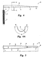
- a tissue retractor 70 is provided as depicted in FIGS. 4-6 .
- the retractor 70 is removably and rotatably insertable through the working channel 25 and the working channel opening 35 of the device 10.
- the tissue retractor 70 includes a working tip 75 configured to atraumatically displace tissue as the retractor 70 is manipulated through the tissue and a body 76 having a proximal first end 77 and a distal second end 78.
- the second end 78 can be integral with the working tip 75 which preferably has a blunt curved end 82.
- the working tip 75 is also preferably bent or curved away from the body 76, as shown in FIG. 7 .
- the body 76 is sized to be rotatably received within the cannula 20 and has a length B from the first end 77 to the second end 78 sufficient so that the first end 77 and the working tip 75 can both extend outside the cannula 20 when the body 76 is within the cannula 20.
- the body 76 includes a curved plate 84 that is configured to conform to the inner cylindrical surface 26 of the cannula without substantially blocking the working channel 25.
- the curved plate 84 has a convex surface 80 and an opposite concave surface 81.
- the curved plate 84 includes a first plate portion 85 defining a first convex surface 80 and an opposite first concave surface 81.
- a second plate portion 86 is integral with the first plate portion 85 and is disposed between the first plate portion 85 and the working tip 75.
- the second plate portion 86 defines a second convex surface (not shown) and an opposite second concave surface 81'. Both the first plate portion 85 and the second plate portion 86 include opposite edges 90 extending substantially parallel to the length B of the body 76.
- the curved plate 84 subtends an arc A 1 between the opposite edges 90 of at least 200 degrees, and most preferably 270 degrees.
- the second plate portion 86 and specifically the second concave surface 81' subtends an angle that decreases along the length of the retractor.
- the second concave surface 81' subtends an angle of about 200 degrees adjacent the first plate portion 85, decreasing to an angle of less than about 10 degrees at end 78.
- FIGS. 8-11 An alternate embodiment of a tissue retractor according to this invention is depicted in FIGS. 8-11 .
- This retractor 100 has a body 106 which includes a first plate portion 115 defining a first convex surface 110 and an opposite first concave surface 111 and includes first opposite edges 120 extending substantially parallel to the length B of the body 106.
- the first plate portion 115 subtends a first arc A 2 between the first opposite edges 120.
- the retractor body 106 also includes a second plate portion 116 which is integral with the first plate portion 115 and is disposed between the first plate portion 115 and a working tip 105.
- the second plate portion 116 defines a second convex surface 110' and an opposite second concave surface 111' and includes second opposite edges 120' extending substantially parallel to the length B.
- the second plate portion 116 subtends a second arc A 3 between the second opposite edges 120' that is different from the first arc A 2 in this embodiment.
- the first arc A 2 subtends an angle of less than 180 degrees and the second arc A 3 subtends an angle of more than 180 degrees.
- the first arc A 2 subtends an angle of about 90 degrees and the second arc A 3 subtends an angle of about 270 degrees.
- the retractors of this invention may be provided with means for engaging the retractors 70, 100 within the working channel 25 of the cannula 20.
- the convex surfaces 80, 110 can be configured to have a diameter that is greater than the diameter D I of the inner cylindrical surface 26 of the cannula 20.
- the body 76, 106 may be formed of a resilient material that is deformable to be insertable into the cannula 20 so that the convex surface 80, 110 is in contact with the inner cylindrical surface 26 of the cannula 20. When the body 76, 106 is deformed, it exerts an outward force against the surface 26 to frictionally hold the retractor in its selected position.
- the preferred components provided by this invention are configured so that multiple tools and instruments can be accepted and manipulated within the working channel 25 of the cannula 20.
- the components are also configured so that more than one surgeon may manipulate instruments through the working channel 25 of the cannula 20 at one time. For example, one surgeon may be manipulating the retractor while another surgeon is drilling into a bone.
- the curvature of the body 76, 106 of the retractors 70, 100 provides more working space and increases visibility.
- Another feature is that the long axis of the component can be placed in the working channel 25 while a bend in the handle portion keeps hands away from the channel 25 so that more than one surgeon can work in the channel 25 and more tools can be placed in the channel 25.
- the arm 71, 101 is at an angle ⁇ which is less than 180 degrees from the longitudinal axis of the length L of the body 76. Most preferably, the angle ⁇ is about 90 degrees so that the arm 71, 101 is substantially perpendicular to the length L of the body 76, 106.
- the arm 71, 101 has a gripping surface 72, 102 to facilitate manipulation of the retractor 70, 100.
- a dilator 130 preferably includes a hollow sleeve 135 defining a channel 131.
- the channel 131 allows the dilator 130 to be placed over a guidewire (not shown) or other dilators.
- the hollow sleeve 135 has a working end 136 defining a first opening 132 in communication with the channel 131 and an opposite end 137 defining a second opening 133.
- the working end 136 is tapered to a tapered tip 138 to atraumatically displace tissue.
- a gripping portion 140 is provided on the outer surface 141 of the sleeve 135 adjacent the opposite end 137.
- the gripping portion 140 is defined by a plurality of circumferential grooves 142 defined in the outer surface 141.
- the grooves 142 are configured for manual gripping of the dilator 130 to manipulate the dilator 130 through tissue.
- the grooves 142 are partially cylindrical.
- the gripping portion 140 includes a number of circumferential flats 143 each of the circumferential grooves 142.
- the grooves 142 have a first width W 1 along the length of the sleeve 135 and the flats 143 have a second width W 2 146 along the length.
- the first and second widths W 1 and W 2 are substantially equal.
- the present invention has application to a wide range of surgical procedures, and particularly spinal procedures such as laminotomy, laminectomy, foramenotomy, facetectomy and discectomy.
- Prior surgical techniques for each of these procedures has evolved from a grossly invasive open surgeries to the minimally invasive techniques represented by the patents of Kambin and Shapiro.
- the minimally invasive techniques represented by the patents of Kambin and Shapiro.
- the devices and instruments of the present invention have application in an inventive surgical technique that permits each of these several types of surgical procedures to be performed via a single working channel.
- This invention can also be used from any approach and in other regions besides the spine.
- the invention contemplates apparatus appropriately sized for use in transnasal, transphenoidal and pituitary surgeries.
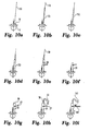
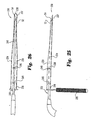
- a guidewire 150 can be advanced through the skin and tissue into the laminae M of a vertebral body V.
- a small incision is made in the skin to facilitate penetration of the guidewire through the skin.
- the guidewire which may be a K-wire, is inserted under radiographic or image guided control to verify its proper positioning within the laminae L of the vertebra V.
- the guidewire 150 can be positioned at virtually any location in the spine and in any portion of a vertebra V. The positioning of the guidewire is dependent upon the surgical procedure to be conducted through the working channel cannula of the present invention.
- the guidewire 150 is solidly anchored into the vertebral bone, being tapped by a mallet if necessary.
- a series of tissue dilators are advanced over the guidewire 150, as depicted in steps (b)-(d) in FIG. 10 .
- the dilators can be advanced through the incision without the aid of a guidewire, followed by blunt dissection of the underlying tissues.
- a series of successively larger dilators 151, 152 and 153 are concentrically disposed over each other and over the guidewire 150 and advanced into the body to sequentially dilate the perispinous soft tissues.
- the tissue dilators are of the type shown in FIG. 9 of the present application.
- the dilators have successively larger diameters, ranging from 5mm, to 9mm to 12.5mm for the largest dilator.
- Other dilator sizes are contemplated depending upon the anatomical approach and upon the desired size of the working channel.
- the working channel cannula 20 is advanced over the largest dilator 153, as shown in step (e), and the dilators and guidewire 150 are removed, as shown in step (f).
- the working channel cannula 20 has an inner diameter D I of 12.7mm so that it can be easily advanced over the 12.5mm outer diameter of the large dilator 153. Larger working channel cannulas are contemplated depending upon the anatomical region and surgical procedure.
- the cannula 20 With the cannula 20 in position, a working channel is formed between the skin of the patient to a working space adjacent the spine. It is understood that the length of the cannula 20 is determined by the particular surgical operation being performed and the anatomy surrounding the working space. For instance, in the lumbar spine the distance between the laminae M of a vertebra V to the skin of the patient requires a longer cannula 20 than a similar procedure performed in the cervical spine where the vertebral body is closer to the skin. In one specific embodiment in which the cannula 20 is used in a lumbar discectomy procedure, the cannula has a length of 87mm, although generally only about half of the length of the cannula will be situated within the patient during the procedure.
- the working channel cannula 20 is at least initially only supported by the soft tissue and skin of the patient.
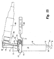
- the cannula 20 can include a mounting bracket 27 affixed to the outer surface of the cannula ( FIG. 10(f) , FIG. 11 ).
- This mounting bracket 27 can be fastened to a flexible support arm 160, which can be of known design.
- the flexible support arm 160 is engaged to the bracket 27 by way of a bolt and wing nut 161, as shown in FIG. 10 (i) and in more detail in FIG. 11 , although other fasteners are also contemplated.
- This flexible arm 160 can be mounted on the surgical table and can be readily adjusted into a fixed position to provide firm support for the cannula 20.
- the flexible arm 160 is preferred so that it can be contoured as required to stay clear of the surgical site and to allow the surgeons adequate room to manipulate the variety of tools that would be used throughout the procedure.
- the fixture 30 can be engaged over the proximal end of the cannula 20.
- the fixture 30, as shown in FIGS. 2 and 3 and as described above, provides an optics bore 60 for supporting an elongated viewing element, such as element 50 shown in step h.
- the viewing element 50 is advanced into the fixture 30 and supported by the optics bore 60 ( FIG. 2 ).
- the element 50 is most preferably a fiber optic scope, although a tod lens scope, "chip on a stick" or other viewing scopes may be utilized.
- the flexible arm 160 is mounted to the bracket 27 to support the cannula 20 which in turn supports the optical viewing element 50.
- This final position of step (i) in FIG. 10 is shown in more detail in FIG. 11 .
- the viewing element 50 can be of a variety of types, including a rigid endoscope or a flexible and steerable scope.
- the surgeon can directly visualize the area beneath the working channel 25 of the cannula 20.
- the surgeon can freely manipulate the viewing element 50 within the working channel 25 or beyond the distal end of the cannula into the working space.
- the second end 52 of the viewing element 50 which carries the lens 55, can be manipulated to different positions, such as shown in FIG. 11 .
- the manipulation and positioning of the scope is not limited by the working channel 25, in contrast to prior systems.
- the positioning capability provided by the fixture 30 is utilized to allow extension of the lens 55 into the working space or retraction back within the cannula 20, as depicted by the arrows T in FIG. 1 .
- the fixture preferably accommodates rotation of the element 50 about its own axis (arrows R in FIG. 1 ) to vary the viewing angle provided by the angled lens 55, or rotation of the entire viewing element 50 about the cannula 20 and around the circumference of the working channel 25, as shown by the arrows N in FIG. 1 .
- the surgeon is provided with a complete and unrestricted view of the entire working space beneath the working channel 25.
- the viewing orientation of the optics i.e., left-right and up-down
- the cannula 20 of the present invention can be readily positioned over an appropriate target tissue or bone, to thereby move the working space as necessary for the surgical procedure.
- the working channel cannula 20 since the working channel cannula 20 is freely situated within the patient's skin and tissue, it can be manipulated so that the working space beneath the cannula 20 is more appropriately centered over the target region of the spine.
- Repositioning of the cannula 20 can be performed under fluoroscopic guidance.
- the cannula may be fitted with position sensing devices, such as LEDs, to be guided stereotactically. As the cannula is being repositioned, the surgeon can also directly visualize the spine through the viewing element 50.
- a variety of tools and instruments can be extended through the working channel 25 to accomplish the particular surgical procedure to be performed. For instance, in the case of a laminotomy, laminectomy, foramenotomy or facetectomy, a variety of rongeurs, curettes, and trephines can be extended through the working channel opening 35 (see FIG. 2 ) and through the working channel 25 of the cannula 20 (see FIG. 11 ) into the working space. It is understood that these various tools and instruments are designed to fit through the working channel.
- the working channel 25 through the cannula 20 can have a maximum diameter d 2 of 12.7mm.
- the effective diameter is about 8mm in the specific illustrated embodiment, although adequate space is provided within the working channel 25 around the viewing element 50 to allow a wide range of movement of the tool or instrument within the working channel.
- the present invention is not limited to particular sizes for the working channel and effective diameter, since the dimensions of the components will depend upon the anatomy of the surgical site and the type of procedure being performed.
- each of the tools and instruments used with the working channel cannula 20 are designed to minimize obstruction of the surgeon's visualization of and access to the working space at the distal end of the working channel cannula.
- the instruments and tools are designed so that their actuating ends which are manipulated by the surgeon are displaced from the working channel cannula 20.
- One such example is the tissue retractor shown in FIGS. 4-8 . With these retractors, the handles that are manually gripped by the surgeon are offset at about a 90 degree angle relative to the longitudinal axis of the tool itself.
- the surgical procedures conducted through the working channel cannula 20 and within the working space at the distal end of the cannula are performed "dry" - that is, without the use of irrigation fluid.
- the working space at the surgical site is fluid filled to maintain the working space and to assist in the use of the visualization optics.
- the visualization optics were fixed within the endoscope.
- the device 10 of the present invention allows a wide range of movement for the viewing element 50 so that the lens 55 can be retracted completely within the working channel 25 of the cannula 20 to protect it from contact with the perispinous tissue or blood that may be generated at the surgical site.
- the viewing element 50 since the viewing element 50 is removable and replaceable, the element 50 can be completely removed from the fixture 30 so that the lens 55 can be cleaned, after which the viewing element 50 can be reinserted into the fixture and advanced back to the working space. Under these circumstances, then, the need for irrigation is less critical.
- This feature can be of particular value when cutting operations are being performed by a power drill. It has been found in prior surgical procedures that the use of a power drill in a fluid environment can cause turbulence or cavitation of the fluid. This turbulence can completely shroud the surgeon's view of the surgical site at least while the drill is being operated. With the present invention, the dry environment allows continuous viewing of the operation of the power drill so that the surgeon can quickly and efficiently perform the necessary cutting procedures.
- irrigation may be provided separately through the working channel 25.
- the viewing device 50 itself may include a tube 54 supported by the fitting 53 through which modest amounts of fluid can be provided to keep the visualization space clear.
- aspiration of the excised tissue is preferred, and irrigation will frequently assist in rapid removal of this tissue.
- separate irrigation and aspiration elements can also be inserted through the working channel 25 as required by the procedure.
- an aspiration cap 165 is provided as shown in FIGS. 11 and 12 .
- the cap 165 includes a body 166 which defines a mating bore 167 having an inner diameter d b larger than the outer diameter D h of the housing 31 of fitting 30.
- a tool opening 168 is provided in communication with the mating bore 167.
- the tool opening 168 communicates directly with the upper bore 41 and provides the same entry capabilities as the working channel opening 35 of the housing 31.
- the aspiration cap 165 is also provided with a tube receiver bore 169 which intersects the mating bore 167.
- the receiver bore 169 is configured to receive an aspiration tube through which a vacuum or suction is applied.
- the tool opening 168 may be covered while suction is applied through the tool receiver bore 169 and mating bore 167, and ultimately through the working channel 25. Covering the opening 168 can optimize the aspiration effect through the working channel.
- the paraspinous tissue can be reflected using instruments as described above, and a laminectomy performed using various rongeurs, curettes and drills.
- the cannula 20 can be angled to allow a greater region of bone removal, which may be necessary for access to other portions of the spinal anatomy.
- access to the spinal canal and the posterior medial aspects of the disc annulus may require cutting a portion of the vertebral bone that is greater than the inner diameter of the working channel 25.
- multi-level laminectomies or foramenotomies may be necessary.
- these multi-level procedures can be conducted by sequentially inserting the working channel cannula 20 through several small cutaneous incisions along the spinal mid-line.
- several working, channel cannulas 20 can be placed at each of the small cutaneous incisions to perform the multi-level bone removal procedures.
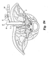
- an opening is cut into the laminae M of the vertebra V providing direct visual access to the spinal canal itself.
- tissue surrounding the spinal nerve root can be removed utilizing micro surgical knives and curettes.
- a retractor such as the retractors shown in FIGS. 4-8 , can be used to gently move and hold the nerve root outside the working space.
- the portion of the retractor passing through the working channel 25 generally conforms to the inner surface of the cannula 20 so that the working channel 25 is not disrupted by the retractor tool.
- the effective diameter within the working channel 25 is reduced only by the thickness of the curved plates 84, 114 of the retractors 70, 100.
- this thickness is about 0.3mm, so it can be seen that the tissue retractors do not significantly reduce the space available in the working channel 25 for insertion of other tools and instruments.
- bone within the spinal canal can be removed with a curette or a high speed drill.
- the fractured bone may be impacted back into the vertebral body with a bone impactor.
- the spinal procedure to be performed is the removal of epidural spinal tumors
- the tumors can be resected utilizing various micro-surgical instruments.
- the dura may be opened and the intradural pathology may be approached with micro-surgical instruments passing through the working channel cannula 20.
- the nerve root retracted posterior medial disc herniations can be readily excised directly at the site of the herniation.
- a working channel cannula such as cannula 20
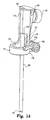
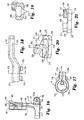
- the fixture 170 includes a scope body 171 which is shown most clearly in FIGS. 13 , 14 , 16 and 17 .
- the scope body 171 includes a clamping ring 172 configured to encircle the outer surface 23 of the cannula 20.
- the clamping ring 172 includes an inner clamping surface 175 (see FIG. 14 ). That clamping surface 175 has substantially the same configuration and dimension as the outer surface 23 of the cannula 20.
- the clamping ring 172 includes clamp arms 173a, b at the free ends of the ring.
- the clamp arms 173a, b define a slot 174 (see FIG. 17 ) therebetween.
- the clamping ring 172 is integral with a support column 176 forming part of the scope body 171.
- a column slot 177 is formed in the support column 176, with the column slot 177 being contiguous with the slot 174 between the clamp arms 173a, b.
- the slots 174 and 177 permit the clamp arms 173a, b to be compressed toward each other to thereby compress the clamping surface 175 of the ring 172 about the outer surface 23 of the cannula 20. In this manner, the fixture 170 can be affixed at a specific position on the cannula 20.
- the fixture 170 when the clamping ring 172 is loosened, the fixture 170 is free to rotate about the circumference of the cannula 20 in the direction of the arrow N. In addition, the fixture 170 can translate along the longitudinal length of the cannula 20 in the direction of the arrow T. Of course, the direction of the travel distance of the fixture 170 along the length of the cannula 20 is limited by the proximal end 22 and the bracket 27 used to engage a supporting flexible arm 160 as described above.
- the fixture 170 includes an optics mounting body 178 that is supported by and preferably integral with the support column 176.
- the optics mounting body 178 defines a stop edge 179 at the interface between the support column 176 and the mounting body 178. This stop edge defines the height of the support column from the clamping ring 172 to the stop edge 179.
- the stop edge 179 of the optics mounting body 178 can be used to limit the downward travel of the fixture 171 in the direction of the arrow T, which can be particularly important in embodiments of the cannula 20 that do not include the bracket 27.
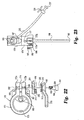
- the optics mounting body 178 defines an optics bore 180 which is configured to receive and support an optics cannula 190.
- the optics bore 180 can communicate with an illumination port 181 which can receive an illumination source, such as a fiber optic light cable.
- the optics bore 180 also communicates with an optics coupling bore 182 projecting from a front face of the fixture 170.
- the fixture 170 also includes a coupling body 183 that is preferably press-fit within the optics coupling bore 182. As shown in FIG. 15 , the coupling body 183 can be engaged by a coupler 184 to support a camera 185 thereon.
- an aspiration port 186 and an irrigation port 187 can be provided that communicates with the optics bore 180.
- the optics cannula 190 includes channels along its length to correspond to the various ports in the optics mounting body 178.
- the port 181 is not used, with the port 186 being used to receive an illumination element.
- the port 187 can be connected to an aspiration circuit.
- the port 187 can be engaged to an aspiration tube 225 which carries a flow control valve 226 and Luer® fitting 227 at its free end.
- the Luer@ fitting 227 can engage a source of irrigation fluid or aspiration vacuum pressure depending upon the particular use envisioned for the port 187 and a corresponding channel within the optics cannula 190.
- the port 187 is used as an aspiration port with the Luer® fitting 227 connected to a vacuum source. It is understood that the port 187 is in fluid communication with a corresponding channel in the optics cannula 190 so that suction applied through the tube 225 and port 187 is drawn through the distal or working end 192 of the optics cannula 190.
- the working end 192 is at the surgical site so that the suction draws air through the working channel 25 of the cannula 20, to the surgical site and through the aspiration/irrigation channel in the optics cannula 190. It has been found that providing aspiration suction in this manner eliminates smoke that may be developed during operation of certain instruments, such as a Bovie.
- the suction applied through the port 187 can draw air across the lens 191 (see FIG. 14 , 15 ) of the optics cannula 190, to prevent fogging of the lens. If a separate aspiration tube is extended through the working channel, defogging of the lens 191 is best achieved with the opening of the aspiration tube adjacent the lens. In this manner,. the provision of aspiration vacuum through the working channel and working space virtually eliminates the need to retract the optics cannula 190 to clean the lens 191. This is in contrast to prior devices in which either the lens had to be removed from the surgical site for cleaning or devices in which substantial flow of fluid is required to keep the lens clean and clear.
- the barrel clamp mechanism 195 compresses the arms 173a, b of the clamping ring 172 together to clamp the fixture 170 to the cannula 20.
- the barrel clamp mechanism 195 includes a barrel cam 196 disposed immediately adjacent one of the clamp arms 173b, and a lever arm 197 that operates to compress the barrel cam 196 against the clamp arm 173.
- a shoulder screw 198 fixes each of these components together.
- the shoulder screw 198 includes a threaded shank 199 that is configured to engage a mating threaded bore 202 in one of the clamp arms 173a.
- the shoulder screw 198 includes a bearing shank 200 that is smooth or non-threaded.
- the bearing shank 200 is received within a bearing bore 203 in the clamp arm 173b, a colinear bearing bore 204 in the barrel cam 196, and a bearing bore 205 in the lever arm 197.
- the shoulder screw 198 further includes an enlarged head 201 which is preferably received within a head recess 206 in the lever arm 197 (see FIG. 19 ).
- the enlarged head 201 of the shoulder screw includes a driving tool recess to mate with a driving tool to thread the threaded shank 199 of the screw into the mating threaded bore 202 of the clamp arm 173a. It is understood that the barrel cam 196 and lever arm 197 are free to rotate about the bearing shank 200 of the shoulder screw 198.
- the lever arm 197 includes an arm 210 that is integral with a body 211.
- the bearing bore 205 and head recess 206 are defined in the body 211.
- the body 211 defines a pair of projections 212 on opposite sides of the bearing bore 205.
- each of the projections 212 includes a rounded tip 213 to provide a smooth sliding surface.
- the barrel cam 196 includes a flat face 215 that faces the clamp arm 173b.
- the flat face provides for smooth rotation of the barrel cam 196 relative to the stationary arm 173b.
- the opposite face of the barrel cam 196 is a cam face 216 that includes a pair of diametrically opposite cam portions 217.
- the cam portions 217 define a ramp 218 that is inclined upward to a detent recess 219.
- Each detent recess 219 terminates in a stop 220 that is higher relative to the base detent recess 219 than the ramp 218.
- the barrel clamp mechanism 195 operates to compress the arms 173a, b of the clamping ring 172 together when the lever arm 197 is rotated about the shoulder screw 198. Specifically, as the lever arm 197 is rotated, the projections 212 slide on their rounded tip 213 along the ramps 218 until the rounded tips 213 fall within the opposite detents 219. As the projections 212 move up the ramps 218, the projections 212 push the barrel cam 196 toward the clamp arms 173a, b. More specifically, since the opposite clamp arm 173a is held relatively fixed by the threaded shank 199 of the shoulder screw 198, the movement of the barrel cam 196 presses the clamp arm 173b against the relatively stationary clamp arm 173a.
- the clamping ring 172 is tightened around the outer surface 23 of the cannula 20.
- the fixture is locked onto the cannula 20. It is understood that the recesses 219 are shallow enough to permit ready manual disengagement of the projections 212 from the recesses 219 as the lever arm 197 is rotated in the opposite direction.
- the detent recesses 219 are 180° opposite each other.
- the ramps 218 are curved and subtend an angle of about 90°.
- the lever arm 197 rotates through 90° to move the projections 212 from one end of the cam ramps 218 to the recesses 219.
- the lever arm ninety degree movement moves the arm from a first position in which the arm 197 is substantially parallel to the cannula, to a second position in which the arm is substantially perpendicular to the cannula. Most preferably, in the second position the arm is oriented immediately adjacent the cannula, rather than projecting away.
- the lever arm 197 maintains a low profile so as not to interfere with the surgeon's manipulation of tools and instruments through the working channel.
- the first position of the lever arm corresponds to the loose or unlocked position of the barrel clamp mechanism 195, while the second position corresponds to the locked configuration.
- the barrel cam 196 remain stationary relative to the moveable lever arm 197, with the exception that the barrel cam 196 is free to translate along the length of the shoulder screw 198. Consequently, the clamp arm 173b includes a recess 222 that has a configuration substantially similar to the outer periphery of the barrel cam 196. In this manner, the barrel cam can be slightly indented within the clamp arm 173b so that the cam is unable to rotate about the shoulder screw 198 as the lever arm 197 is pivoted.
- the components of the fixture 170 are formed of a flexible and resilient material.
- the scope body 171 can be formed of a plastic, such as polycarbonate.
- the scope body 171 lends itself particularly well to typical plastic molding techniques.
- the barrel cam 196 and lever arm 197 can be molded from a plastic material.
- these components are formed of Delrin®, since Delrin® provides a smooth surface for the relative movement between the projections 212 on the lever arm 197 and the cam face 216 of the barrel cam 196.
- the travel of the barrel clamp mechanism 195 can be calibrated sufficient to tightly compress the clamping rings 172 about the cannula 20. It is also understood that this compression must not be so great as to compromise the integrity or strength of the cannula 20.
- the slot 174 is larger than the maximum travel of the barrel clamp mechanism 195 so that the projections 212 of the lever arm 197 can rest solidly within the detent recesses 219 of the barrel cam 196.
- the slot 174 has a dimension of 2.0mm while the throw of the barrel clamp mechanism 195 achieved by the barrel cam 196 is 1.0mm.
- the fixture 170 supports an optics cannula 190 in a fixed orientation relative to the scope body 171.
- the optics cannula 190 is not permitted to rotate about its axis as could the scope 50 of the embodiment shown in FIG. 1 .
- the lens 191 is therefore mounted at an angle B relative to the distal end of the optics cannula 190.
- the lens 191 is situated at an angle B of 30°.
- the lens has an optical axis that is angled toward the center of the working space 25 or the cannula 20.
- the lens 191 has a fixed orientation relative to the scope body 171, the lens can still be rotated around the working space by rotation of the fixture 170 about the outer surface 23 of the cannula 20.
- the lens 191 and the optical system provide a depth of field of view that allows the surgeon to view anatomy outside the working channel 25.
- the fixture 170 allows rotation of the optics cannula 190 around the working space and translation of the optics cannula 190 and 191 along the longitudinal axis of the working channel 25.
- the surgeon can achieve these motions by releasing the barrel clamp mechanism 195 and then re-engaging the clamp by rotating the lever arm 197 to its locked position.
- the optics cannula 190 is sized so that the lens 191 can project beyond the distal end 21 of the cannula 20.
- the fixture 170 allows the retraction of the lens 191 and optics cannula 190 within the working channel 25 and cannula 20.
- the fixture 170 permits up to 15mm travel along the direction of the arrow T with 7.5mm of the travel being within the working space 25 and 7.5mm of the travel being beyond the distal end 21 of the cannula 20.
- this 15mm travel distance is related to the height of the support column 176 from the top of the clamping ring 172 to the stop edge 179 of the optics mounting body 178.
- the amount of extension of the lens 191 of the optics cannula 190 beyond the distal end 21 of the cannula 20 is also based upon the overall length of the optics cannula 190 relative to the overall length of the working channel cannula 20.
- the optics cannula 190 has a length of 100mm measured from the lens 191 to the stop edge 179 of the optics mounting bore 178.
- the optics cannula is longer than this 100mm distance because a portion of the cannula is supported within the optics bore 180 of the optics mounting body 178.
- the cannula 20 has an overall length of 92mm from its distal end 21 to its proximal end 22 (see FIG. 15 ).
- the overall length of the cannula, and consequently the optics cannula 190 is determined, in part, by the spinal anatomy.
- placement of the proximal end 22 of the working channel 25 too distant from the surgical site at the distal end 21, causes the surgeon to lose tactile feel while manipulating certain instruments.
- a certain amount of "feel" is required so that the surgeon can accurately perform the respective operations with the instrument. If the distance between the surgical site and the manual end of the instrument is too great, the surgeon will not be able to stably and comfortably operate the instrument.
- the working channel cannula 20 must have a length that is limited relative to the distance L ( FIG. 24 ) between the vertebral laminae and the surface of the skin. In the lumbar region of the spine, this distance is approximately 65-75mm. Consequently, in one embodiment of the invention, the working channel cannula 20 has first portion of its length somewhat less than the anatomic distance. In one specific embodiment, this length of the first portion is about 66mm from the distal end 21 to the mounting bracket 27. In some surgical applications, the mounting bracket 27 may actually rest against the skin of the patient so that the distal end 21 of the working channel cannula can be closer to the surgical site.
- the remaining second portion of the length of the cannula 20 above the mounting bracket 27 is minimized. In accordance with the invention, this distance must be sufficient to permit extension and retraction of the lens 191 relative to the distal end 21 of the cannula 20.
- the travel of the optical lens 191 is preferably 15mm, so that the remaining length of the cannula 20 is about 26mm to accommodate this travel and to provide adequate surface for engagement by the clamping ring 172.
- the working channel cannula 20 has an overall length of 92mm.
- the relative length between the first portion of the cannula disposed within the patient to the second portion of the cannula length situated outside the patient have a ratio of 2:1 to 3:1.
- the length of the first portion is between two to three times longer than the length of the second portion.
- the optics mounting body 178 has a height of about 21mm between the stop edge 179 and the top face of the body 178. This distance is not so great that the surgeon is restrained from manipulating instruments directly above the fixture 170. Of course, it is preferable that the surgeon manipulate the instruments directly above the proximal end 22 of the working channel 20 immediately adjacent to the fixture 170.
- the working channel cannula has an inner diameter of about 15mm and an outer diameter of about 16mm.
- the cannula can be provided in a smaller size for other regions of the spine.
- the cannula inner diameter is 12.7mm with a 14mm outer diameter.
- the overall length and diameter of the working channel cannula 20 is calibrated again relative to the distance L of the spinal anatomy. With the larger diameter working channel, the surgeon can orient certain instruments at an angle relative to the longitudinal axis of the cannula 20. In specific embodiments, this angle is approximately 5-6°. It has been found that this angle, together with the large working channel 25, gives the surgeon greater flexibility and mobility within the surgical site to perform various operations. To that end, the length and diameter of the working channel cannula 20 is appropriately sized to maintain this flexibility, without getting too large. A working channel cannula 20 that has too large a diameter is less adaptable to the spinal anatomy.
- the working space is generally limited to the region directly adjacent the laminae of a vertebra.
- a cannula having a diameter that is too large will interfere with the spinous process when the working space is created, and will require resection of greater amounts of tissue than is preferred for an optimal percutaneous procedure. Therefore, in accordance with one aspect of the invention, the working channel cannula has a relationship between its length and its diameter to permit tool angles through the cannula of between 5-8°.
- the cannula can have a length to diameter ratio of between about 5.5:1 to 7:1. Further in accordance with the present invention, the working channel cannula has a length that is no more than 20-30mm greater than the distance L ( FIG. 24 ) between the laminae and the skin of the patient.
- the large diameter of the working channel 25 in the cannula 20 allows the surgeon or surgeons conducting the surgical procedure to introduce a plurality of instruments or tools into the working space.
- a tissue retractor and discectomy instruments can be simultaneously extended through the working channel.
- the discectomy instruments could include a trephine for boring a hole through the disc annulus and a powered tissue cutter for excising the herniated disc nucleus.
- the present invention contemplates the simultaneous introduction of other types of instruments or tools as may be dictated by the particular surgical procedure to be performed. For example, an appropriately sized curette and a rongeur may be simultaneously extended through the working channel into the working space.
- the surgeon can readily manipulate each of the instruments to perform tissue removal and bone cutting operations, without having to remove one tool and insert the other.
- the surgical procedures can be conducted without the necessity of irrigation fluid, the surgeon has a clear view through the working space of the target tissue.
- aspects of the invention which permit a wide range of motion to the viewing element 50 allow the surgeon to clearly visualize the target tissue and clearly observe the surgical procedures being conducted in the working space.
- surgeon can capitalize on the same advantages in conducting a wide range of procedures at a wide range of locations in the human body.
- facetectomies could be conducted through the working channel by simply orienting the working channel cannula 20 over the particular facet joints.
- the insertion of vertebral fixation elements can also be accomplished through the device 10.
- an incision can be made in the skin posterior to the location of the vertebra at which the fixation element is to be implanted.
- the cannula 20 can be positioned through the incision and tissue directly above the particular location on the vertebra to be instrumented.
- an insertion tool holding the vertebral fixation element can be projected through the cannula 20 and manipulated at the vertebra.
- the fixation element can be a bone screw.
- the working channel 25 has a diameter that is large enough to accept most bone screws and their associated insertion tools.
- the location of the bone screw within the vertebra is critical, so identification of the position of the cannula 20 over the bony site is necessary. As mentioned above, this position can be verified fluoroscopically or using stereotactic technology.
- cannulated bone screws are driven into the vertebra along K-wires.
- the present invention eliminates the need for the K-wire and for a cannulated screw.
- the working channel itself can effectively operate as a positioning guide, once the cannula 20 is properly oriented with respect to the vertebra.
- the device 10 allows insertion of the bone screw into the vertebra to be conducted under direct vision. The surgeon can then readily verify that the screw is passing into the vertebra properly. This can be particularly important for bone screws being threaded into the pedicle of a vertebra.
- the working channel cannula 20 can be used to directly insert a self-tapping bone screw into the pedicle, or can accept a variety of tools to prepare a threaded bore within the pedicle to receive a bone screw.
- the device 10 can also be used to prepare a site for fusion of two adjacent vertebrae, and for implantation of a fusion device or material.
- a fusion device or material For example, in one surgical technique, an incision can be made in the skin posterior to a particular disc space to be fused. The incision can be made anteriorly, posteriorly or posterior laterally. If the incision is made anteriorly for anterior insertion of the working channel, it is anticipated that care will be taken to retract tissues, muscle and organs that may follow the path of the incision to the disc space.
- the device 10 of the present invention allows this tissue retraction to occur under direct vision so that the surgeon can easily and accurately guide the cannula 20 to the disc space without fear of injury to the surrounding tissue.
- the working channel cannula 20 can be progressively advanced toward the anticipated working space adjacent the vertebral disc.
- the disc space can be prepared for implantation of fusion materials or a fusion device.
- this preparation includes preparing an opening in the disc annulus, and excising all or part of the disc nucleus through this opening.
- a bore is cut through the disc annulus and into the endplates of the adjacent vertebrae.
- a fusion device such as a bone dowel, a push-in implant or a threaded implant can then be advanced through the working channel of device 10 and into the prepared bore at the subject disc space.
- the preparatory steps involve preparing the vertebral endplates by reducing the endplates to bleeding bone. In this instance, some aspiration and irrigation may be beneficial. All of these procedures can be conducted by tools and instruments extending through the working channel cannula 20 and under direct vision from the viewing element 50.
- graft material is simply placed within the prepared bore. This graft material can also be passed through the working channel cannula 20 into the disc space location. In other procedures, graft material or bone chips are positioned across posterior aspects of the spine. Again, this procedure can be conducted through the working channel cannula particularly given the capability of the cannula to be moved to different angles from a single incision site in the skin.
- the present invention provides instruments for conducting a variety of surgical procedures. In the illustrated embodiments, these procedures are conducted on the spine. However, the same devices and techniques can be used at other places in the body. For example, an appropriately sized working channel device 10 can be used to remove lesions in the brain.
- the present invention has particular value for percutaneous procedures. where minimal invasion into the patient is desirable and where accurate manipulation of tools and instruments at the surgical site is required. While the preferred embodiments illustrated above concern spinal procedures, the present invention and techniques can be used throughout the body, such as in the cranial cavity, the pituitary regions, the gastro-intestinal tract, etc. The ability to reposition the viewing optics as required to visualize the surgical site allows for much greater accuracy and control of the surgical procedure.
- the present invention allows the use of but a single entry into the patient which greatly reduces the risk associated with open surgery or multiple invasions through the patient's skin.
- a tissue retractor apparatus 230 that combines a tissue retractor 231 with an optical viewing device 232.
- the retractor apparatus 230 includes a retractor plate 234 that is affixed to a grip 235 for manual support of manipulation of the retractor.
- the grip 235 is at the proximal end 236 of the plate.
- the distal end 237 of the retractor plate preferably has a blunt tip 238 to avoid trauma to tissue upon insertion and manipulation of the tissue retractor.
- the blunt tip 238 is angled slightly away from the plate 234.
- the retractor plate 234 defines an outer retraction surface 239 that can be configured according to the type of surgery being performed.
- the plate 234 is semi-cylindrical in configuration to permit atraumatic retraction of tissue adjacent a surgical site.
- the retractor plate 234 defines a channel 240 that helps define a working channel.
- the retractor 231 is substantially similar to the retractor 70 depicted in FIGS. 4-6 and as described above.
- an optical viewing device 232 is supported within the retractor 231 by way of a number of C-clips 245.
- the C-clips 245 are formed of a resilient material, such as plastic or thin flexible metal, and are affixed to the channel 240 of the retractor plate 234.
- two such C-clips 245 are provided to stably mount the optical viewing device 232 relative to the retractor 231.
- the clips 245 are sized to support an optical viewing device 232 that is configured substantially identical to the viewing device 50 described above.
- the viewing device 232 has a distal tip 52 with an angled lens 54.
- the C-clips 245 provide a resilient friction fit to the optical viewing device 232 while still permitting relative sliding and rotation of the viewing device 232 relative to the retractor 231.
- the tissue retractor apparatus 230 can be used in a variety of applications, including non-spinal applications.
- this tissue retractor can have application in transnasal and transphenoidal surgeries, and in pituitary procedures.
- the smaller working space does not lend itself to the use of a closed cannula which would tend to restrict the space available for manipulation of surgical instruments. Consequently, a tissue retractor or speculum of the type shown in FIGS. 25-26 may be very adequate for surgeries of this type.
- the working channel is defined in part by the patient's body itself, and in part by the tissue retractor.
- the optical viewing device 232 is supported relative to the retractor to permit the same degrees of motion as are available with the device 10 described above.
Claims (59)
- Dispositif destiné à être utilisé dans un acte chirurgical percutané sans espace de travail à maintenu au moyen d'un fluide, comprenant :une canule allongée (20) ayant une dimension interne (DI) et une dimension externe (Do) dont la dimension est conçue pour une introduction percutanée dans un patient ;ladite canule (20) ayant une extrémité de travail distale (21) et une extrémité proximale opposée (22) et délimitant un canal de travail (25) entre lesdites extrémités, ledit canal de travail étant dimensionné pour recevoir un outil à travers lui ;un élément de visualisation (50 ; 190) ayant une première extrémité (51) apte à être connectée à un appareil de visualisation et une seconde extrémité opposée (52 ; 192) disposée au voisinage de ladite extrémité de travail distale de ladite canule ;un élément de fixation (30 ; 170) supportant ledit élément de visualisation (50 ; 190),caractérisé par le fait que ledit élément de fixation supporte ledit élément de visualisation à une position adjacente à et à l'extérieur canas de travail (25) avec ladite seconde extrémité (52 ; 192) disposée au voisinage de ladite extrémité de travail de ladite canule, et par le fait que ledit canal de travail (25) a une dimension interne (d2) sensiblement égale à la dimension interne (DI) de la canule (20) avec ladite élément de fixation supportant ledit élément de visualisation (50 ; 190) au voisinage dudit canal de travail, l'élément de fixation (30 ; 170) étant disposé de telle sorte que, lorsqu'il est monté sur la canule (20), le canal de travail (25) est ouvert à l'extrémité proximale de la canule de façon à permettre la réception dudit outil.
- Dispositif selon la revendication 1, dans lequel ladite dimension interne (d2) du canal de travail (25) est conçue pour recevoir simultanément plusieurs outils à travers lui.
- Dispositif selon l'une des revendications 1 ou 2, dans lequel ledit élément de visualisation (50 ; 190) comprend une lentille (55 ; 191) à ladite seconde extrémité (52) et un canal de transmission d'image s'étendant à partir de celle-ci.
- Dispositif selon l'une quelconque des revendications précédentes, dans lequel ledit élément de visualisation (50 ; 190) est un câble à fibres optiques ayant des fibres d'éclairage et des fibres de transmission d'image.
- Dispositif selon l'une quelconque des revendications précédentes, dans lequel ledit élément de fixation (30 ; 170) est configurée pour monter de façon amovible ledit élément de visualisation (50 ; 190) sur ladite canule (20).
- Dispositif selon la revendication 5, dans lequel ledit élément de fixation (30 ; 170) est configuré pour monter ledit élément de visualisation (50 ; 190) à l'intérieur de ladite canule (20).
- Dispositif selon l'une des revendications 5 ou 6, dans lequel ledit élément de fixation (30 ; 170) comprend des moyens pour monter de façon amovible ledit élément de fixation sur ladite canule (20) au voisinage de ladite extrémité proximale (22) de ladite canule.
- Dispositif selon l'une quelconque des revendications précédentes, dans lequel ladite canule (20) est cylindrique et ledit canal de travail (25) est circulaire.
- Dispositif selon l'une quelconque des revendications précédentes, dans lequel ledit élément de fixation (30 ; 170) comprend : un boîtier (31 ; 178) attaché à l'extrémité proximale (22) de la canule (20), ledit boîtier délimitant une ouverture de canal de travail (35) à travers lui en communication avec le canal de travail (25), ladite ouverture du canal de travail (35) étant dimensionnée pour correspondre sensiblement à ladite dimension interne (Di) dudit canal de travail pour recevoir un outil à travers elle ; ledit boîtier (31 ; 178) délimitant en outre un perçage d'élément optique (60 ; 180) adjacent à ladite ouverture du canal de travail (35), ledit perçage d'élément optique étant dimensionné pour recevoir ledit élément de visualisation (50 ; 190) à travers lui.
- Dispositif selon la revendication 9, dans lequel ledit élément de fixation (30 ; 170) est supporté de façon amovible au voisinage de ladite extrémité proximale (22) de ladite canule (20) au voisinage dudit canal de travail (25), ledit perçage d'élément optique (60 ; 180) ayant un axe longitudinal et étant dimensionné pour recevoir de façon amovible ledit élément de visualisation (50 , 190) à travers lui, et ledit élément de fixation (30 ; 170) supportant ledit élément de visualisation pour un mouvement à l'intérieur dudit perçage d'élément optique (60 ; 180) le long de l'axe longitudinal (1) dudit perçage pour étendre ou rétracter ladite lentille par rapport à ladite extrémité de travail distale de ladite canule (20).
- Dispositif selon l'une des revendications 9 ou 10, dans lequel ledit perçage d'élément optique (60 ; 180) définit un axe longitudinal (1) et ledit élément de fixation supporte l'élément de visualisation (50 ; 190) pour une rotation à l'intérieur du perçage d'élément optique autour dudit axe longitudinal du perçage d'élément optique.
- Dispositif selon l'une des revendications 10 ou 11, dans lequel ladite lentille (55 ; 191) définit un axe optique (Ao), ledit axe optique étant décalé d'un angle par rapport audit axe longitudinal (L) dudit perçage d'élément optique (60 ; 180).
- Dispositif selon l'une des revendications 10, 11 ou 12, dans lequel ledit élément de fixation (30 ; 170) comprend un moyen d'engagement (32; 172) disposé entre ledit boîtier (31 ; 178) et ladite canule (20) lorsque ledit élément de fixation (30 ; 170) est monté sur ladite extrémité proximale (22) de ladite canule, pour fournir un engagement de saisie entre ledit boîtier et ladite canule.
- Dispositif selon la revendication 13, dans lequel ledit moyen d'engagement (32 ; 172) comprend un nombre de bagues élastiques disposées entre ledit boîtier (31 ; 178) et ladite canule (20).
- Dispositif selon l'une quelconque des revendications 9 à 14, dans lequel ladite ouverture du canal de travail (35) est dimensionnée pour recevoir une pluralité d'outils à travers elle, et ledit boîtier (31 ; 178) définit en outre un perçage d'élément optique (60 ; 180) pour recevoir un élément de visualisation (50 ; 190) à travers lui et disposé de telle sorte que l'élément de visualisation reçu à l'intérieur dudit perçage d'élément optique s'étendra dans le canal de travail (25) de la canule (20) lorsque ledit élément de fixation (30 ; 170) sera monté sur la canule.
- Dispositif selon la revendication 15, dans lequel la canule (20) définit un premier axe longitudinal (L), dans lequel ledit perçage d'élément optique (60 ; 180) définit un second axe longitudinal (1) sensiblement parallèle au premier axe longitudinal lorsque ledit élément de fixation (30 ; 170) est monté sur la canule, ledit boîtier (31 ; 178) étant apte à tourner par rapport à ladite canule de telle sorte que ledit second axe longitudinal dudit perçage d'élément optique (60 ; 180) tournée autour du premier axe longitudinal (L) de la canule (20).
- Dispositif selon l'une des revendications 15 ou 16, dans lequel ledit boîtier (31 ; 178) comprend en outre un perçage supérieur (41) contigu à ladite ouverture du canal de travail (35) et en communication avec ledit perçage de réception (40), ledit perçage d'élément optique (60 ; 180) étant disposé à l'intérieur dudit perçage supérieur (41) dudit boîtier.
- Dispositif selon l'une quelconque des revendications 9 à 17, dans lequel ledit perçage d'élément optique (60) est défini par un clip en C (61).
- Dispositif selon la revendication 18, dans lequel ledit clip en C (61) est formé d'une matière élastique et ledit perçage d'élément optique (60) défini par ledit clip a une dimension interne (Di) qui est légèrement inférieure à une dimension externe dudit élément de visualisation (50) de telle sorte que ledit élément de visualisation fasse fléchir de façon élastique ledit clip en C (61) lorsque ledit élément de visualisation (50) est disposé à l'intérieur dudit perçage d'élément optique (60).
- Dispositif selon l'une quelconque des revendications 9 à 19, dans lequel: ladite canule (20) a une dimension externe (D0); et ledit boîtier (31) définit un perçage de réception. (40) ayant une dimension interne (dI) légèrement supérieure à ladite dimension externe (Do) de ladite canule, ladite extrémité proximale (22) de ladite canule étant reçue à l'intérieur dudit perçage de réception (40) de telle sorte que ledit boîtier (31) puisse tourner autour de ladite extrémité proximale de ladite canule.
- Dispositif selon la revendication 20, dans lequel ledit boîtier (31) définit en outre un nombre de rainures (32) dans ledit perçage de réception (40).
- Dispositif selon la revendication 21, comprenant en outre des éléments d'étanchéité disposés dans chacun dudit nombre de rainures (32), lesdits éléments d'étanchéité disposés entre ledit boîtier (31) et ladite dimension externe de ladite canule (20).
- Dispositif selon l'une quelconque des revendications précédentes, dans lequel ledit élément de fixation (30 ; 170) comprend : un corps (31 ; 178) ayant des moyens (32 ; 172) pour engager ledit élément de visualisation (50) ; et des moyens de serrage dudit corps sur ladite canule (20) pour supporter ledit élément de fixation sur ladite canule.
- Dispositif selon la revendication 23, dans lequel ledit moyen pour le serrage comprend : une bague (172) attachée audit corps (178), ladite bague étant dimensionnée pour entourer de façon substantielle ladite canule (20) ; et un moyen pour comprimer (173a, b) ladite bague (172) autour de ladite canule (20), ce par quoi ladite bague saisit ladite canule pour supporter ledit élément de fixation (170) sur celle-ci.
- Dispositif selon l'une des revendications 23 ou 24, dans lequel : ledit corps (178) comprend une colonne de support (176) s'étendant entre ledit corps (178) et ladite bague (172) et configurée pour résider à l'extérieur de la canule (20) ; et ledit corps est configuré de telle sorte que ledit perçage d'élément optique est aligné avec une partie du canal de travail (25) de la canule (20) lorsque ledit élément de fixation est supporté sur la canule.
- Dispositif selon l'une quelconque des revendications 23 à 25, dans lequel ledit moyen pour comprimer ladite bague comprend : une paire d'extrémités libres adjacentes ; une paire de bras opposés (173a, b) s'étendant à partir de l'une correspondante desdites extrémités libres, lesdits bras délimitant une fente (174) entre deux et s'étendant entre lesdites extrémités libres ; et un mécanisme (195) relié audits bras et actionnable pour comprimer lesdits bras l'un vers l'autre.
- Dispositif selon la revendication 26, dans lequel ledit mécanisme (195) comprend: une came périphérique (196) disposée au voisinage d'un bras de ladite paire de bras (173a, b), ladite came périphérique ayant une surface de came (216) avec au moins une rampe inclinée (218) tournée à l'opposé du bras précité de ladite paire de bras ; un moyen pour supporter ladite came périphérique (196) par rapport à ladite paire de bras (173a, b) pour permettre une translation de ladite came périphérique vers ladite paire de bras ; un bras de levier (197) comprenant au moins une projection (212) tournée vers ladite surface de came (216) de ladite came périphérique (196) ; et un moyen pour supporter en rotation ledit bras de levier (197) par rapport à ladite came périphérique avec ladite au moins une projection en contact sensiblement continu avec ladite surface de came (216) de ladite came périphérique (196), ce par quoi une rotation dudit bras de levier (197) par rapport à ladite came périphérique (196) amène ladite projection (212) à coulisser le long de ladite rampe (218) pour pousser ladite came périphérique (196) vers ladite paire de bras (173a, b) et ladite paire de bras ensemble.
- Dispositif selon la revendication 27 dans lequel ledit mécanisme comprend en outre : un alésage taraudé (202) dans un bras de ladite paire de bras (173a, b) de façon distale par rapport à ladite came périphérique (196) ; des alésages de palier (203, 204, 205) définis dans l'autre bras de ladite paire de bras (173a, b), ladite came périphérique (196) et ledit bras de levier (197), lesdits alésages de palier (203, 204, 205) étant alignés et coaxiaux avec ledit alésage taraudé (202) ; et une vis à épaulement (198) ayant une tige filetée (199) pour s'apparier avec ledit alésage taraudé ; une tige de palier non filetée (200) s'étendant à travers lesdits alésages de palier (203, 204, 205) et une tête (201) plus grande que lesdits alésages de palier pour engager ledit bras de levier (197) lorsque ladite tige filetée est engagée à l'intérieur dudit alésage taraudé.
- Dispositif selon la revendication 28, dans lequel: ladite came périphérique (196) a une surface (215) opposée à ladite rampe inclinée (218) disposée au voisinage dudit autre bras desdits bras (173a, b) ; et ledit autre bras desdits bras comprend une cavité se conformant à et recevant ladite surface (215) de ladite came périphérique.
- Dispositif selon la revendication 27, dans lequel ladite surface de came (216) de ladite came périphérique (196) comprend une cavité (219) à une extrémité de ladite rampe inclinée (218), ladite cavité étant dimensionnée pour recevoir ladite projection (212) dudit bras de levier (197) dans celle-ci.
- Dispositif selon la revendication 27, dans lequel ladite au moins une rampe inclinée (218) est arquée.
- Dispositif selon la revendication 31, dans lequel : ladite rampe inclinée arquée (218) sous-tend un angle d'environ quatre-vingt-dix degrés (90°), ce par quoi ledit bras de levier (197) est tourné de quatre-vingt-dix degrés (90°) alors que la projection (212) se déplace d'une extrémité de ladite rampe à l'autre.
- Dispositif selon la revendication 32, dans lequel ledit moyen pour supporter en rotation ledit bras de levier (197) supporte ledit bras de levier pour tourner sur quatre-vingt-dix degrés (90°) d'une première position dans laquelle le bras de levier est sensiblement parallèle à ladite longueur de ladite canule (20) à une seconde position dans laquelle le bras de levier (197) est sensiblement perpendiculaire à ladite longueur de ladite canule (20).
- Dispositif selon la revendication 27, dans lequel : ladite surface de came (216) de ladite came périphérique (196) comprend deux rampes inclinées (218) ; et ledit bras de lever (197) comprend deux projections (212) en contact avec l'une correspondante desdites rampes inclinées.
- Dispositif selon la revendication 27, dans lequel ladite au moins une projection (212) comprend une pointe arrondie (213) pour un contact coulissant avec ladite au moins une rampe inclinée (218).
- Dispositif selon la revendication 26, dans lequel ledit moyen pour comprimer ladite bague comprend en outre une fente (177) définie dans ledit corps (171) contiguë à ladite fente (174) définie entre lesdites extrémités libres de ladite bague (172).
- Dispositif selon la revendication 26, dans lequel : ledit élément de visualisation (50) comprend une canule d'élément optique (190) portant ledit canal de transmission d'image ayant un canal d'irrigation/aspiration s'étendant à travers elle ; et ledit corps (171) dudit élément de fixation (170) ayant un corps délimitant un orifice d'irrigation/aspiration (186, 187) en communication avec ledit canal d'irrigation/aspiration lorsque ledit élément de visualisation (50) est supporté par ledit élément de fixation, ledit orifice (186, 187) étant apte à être connecté à une source de fluide d'irrigation ou de vide d'aspiration.
- Dispositif selon l'une quelconque des revendications précédentes, dans lequel: ledit élément de visualisation (50) comprend une canule d'élément optique (190) ayant une extrémité proximale fixée audit élément de fixation et une extrémité distale (192) supportant ladite lentille (191) ; et ledit élément de fixation comprend une bague (172) montée de façon coulissante pour une translation le long de et une rotation autour de ladite canule (20), ce par quoi l'on peut faire varier la position de ladite lentille (191) par rapport à ladite extrémité distale (21) de ladite canule (20) par le déplacement de ladite bague par rapport à ladite canule.
- Dispositif selon la revendication 38, dans lequel ladite canule d'élément optique (190) a une longueur supérieure à ladite longueur de ladite canule allongée (20).
- Dispositif selon la revendication 38, dans lequel ladite canule d'élément optique (190) supportant ladite lentille (191) a un axe (L) orienté à un angle par rapport à un axe longitudinal (L) de ladite canule allongée (20).
- Dispositif selon la revendication 40, dans lequel ladite canule d'élément optique (190) est fixée audit élément de fixation de telle sorte que ledit axe optique est incliné vers ledit canal de travail (25) de ladite canule allongée (20).
- Dispositif selon l'une quelconque des revendications précédentes, approprié pour être utilisé dans un acte chirurgical percutané sur la colonne vertébrale, dans lequel : la canule allongée (20) a une longueur le long d'un axe longitudinal (L) d'une extrémité de travail distale (21) à une extrémité proximale opposée (22), une première partie de ladite longueur étant dimensionnée pour une introduction dans le patient au voisinage de la colonne vertébrale et ayant une longueur inférieure à la distance de la lame de la vertèbre spinale à la peau du patient, et une seconde partie de ladite longueur externe par rapport au patient et étant d'environ un quart (1/4) de la longueur de ladite première partie.
- Dispositif selon l'une quelconque des revendications précédentes, approprié pour être utilisé dans un acte chirurgical percutané sur la colonne vertébrale, dans lequel : ladite colonne allongée (20) a une longueur le long de l'axe longitudinal allant d' une extrémité de travail distale (21) à une extrémité proximale opposée (22), une partie de ladite longueur étant dimensionnée en vue d'une introduction dans le patient au voisinage de la colonne vertébrale, ladite canule ayant une dimension transversale dans un plan perpendiculaire audit axe longitudinal, ladite dimension transversale étant sensiblement constante le long d'au moins la longueur de ladite partie, ladite longueur de ladite canule étant entre 5,5-7,0 fois plus grande que ladite dimension transversale.
- Coffret pour effectuer une opération chirurgicale à un emplacement dans le corps d' un patient, comprenant : une série de dilatateurs tissulaires (151, 152, 153) ayant des diamètres de plus en plus grands pour une introduction séquentielle à travers la peau et le tissu du patient ; une canule (20) dimensionnée pour l'introduction sur le plus grand desdits dilatateurs pour définir un canal de travail (25) à travers la peau et le tissu du patient après retrait desdits dilatateurs dimensionné pour recevoir un outil à travers lui, ladite canule (20) ayant une extrémité proximale (22) et une extrémité distale opposée (21), un axe longitudinal (L) entre lesdites extrémités et une longueur le long dudit axe longitudinal dimensionnée de telle sorte que ladite extrémité distale est adjacente à l'emplacement dans le corps du patient et ladite extrémité proximale est à l'extérieur du corps du patient ; un élément de visualisation (50) apte à s'étendre dans ladite canule (20), ledit élément de visualisation ayant une extrémité de visualisation (52) pouvant être positionnée au voisinage de l'extrémité distale (21) de ladite canule ; un élément de fixation (31, 170) pour supporter ledit élément de visualisation (50) à une position adjacente à et à l'extérieur dudit canal de travail avec ladite seconde extrémité adjacente à ladite extrémité de travail de ladite canule ; et dans lequel ledit canal de travail (25) de ladite canule (20) a une dimension interne (d2) sensiblement égale à la dimension interne (dI) de la canule avec ledit élément de fixation (31 ; 170) supportant ledit élément de visualisation au voisinage dudit canal de travail (25), l'élément de fixation (30 ; 170) étant disposé de telle sorte que, lorsqu'il est monté sur la canule (20), le canal de travail (25) est ouvert à l'extrémité proximale de la canule de façon à permettre une réception dudit outil.
- Coffret selon la revendication 44, comprenant en outre un écarteur tissulaire (70 ; 100), ledit écarteur comprenant : une pointe de travail (75) configurée pour déplacer de façon atraumatique du tissu alors que l'écarteur est manipulé à travers le tissu; et un corps (76 ; 106) ayant une première extrémité proximale (77) et une seconde extrémité distale (78), ladite seconde extrémité étant d'un seul tenant avec ladite pointe de travail, ledit corps ayant une surface convexe (80 ; 110) configurée pour se conformer à la surface cylindrique interne de la canule (20) lorsque ledit écarteur tissulaire (70 ; 100) est disposé à l'intérieur de la canule, ledit corps étant dimensionné pour être reçu en rotation à l'intérieur de la canule et ayant une longueur allant de ladite première extrémité à ladite seconde extrémité suffisante de telle sorte que ladite première extrémité (77) et ladite pointe de travail (75) peut être à l'extérieur de la canule (20) lorsque ledit corps (76 ; 106) se trouve à l'intérieur de la canule (20).
- Coffret selon la revendication 45, dans lequel ladite pointe de travail (75) dudit écarteur tissulaire (70 ; 100) a une extrémité incurvée émoussée.
- Coffret selon la revendication 46, dans lequel ledit corps (76 ; 106) dudit écarteur tissulaire (70 ; 100) comprend une plaque incurvée (84 ; 115) délimitant ladite surface convexe (80; 110) et une surface concave opposée (81 ; 111).
- Coffret selon la revendication 47, dans lequel ladite plaque incurvée (84 ; 115) dudit écarteur tissulaire (70 ; 100) comprend des bordures opposées (90 ; 120) s'étendant sensiblement parallèlement à ladite longueur dudit corps (76 ; 106), ladite plaque incurvée sous-tendant un arc entre lesdites extrémités opposées d'au moins 200 degrés.
- Coffret selon la revendication 48, dans lequel ladite plaque incurvée (84 ; 115) sous-tend un arc entre lesdites extrémités opposées (90 ; 120) d'environ 270 degrés.
- Coffret selon la revendication 44, dans lequel ledit corps (76 ; 106) comprend: une première partie de plaque (85 ; 115) définissant une première surface convexe (80 ; 110) et une première surface concave opposée (81 ; 111) et comprenant des premières bordures opposées (90 ; 120) s'étendant sensiblement parallèlement à ladite longueur dudit corps, ladite première partie de plaque sous-tendant un premier arc entre lesdites premières bordures opposées ; et une seconde partie de plaque (86 ; 116) d'un seul tenant avec ladite première partie de plaque (85 ; 115) et disposée entre ladite première partie de plaque et ladite pointe de travail (75), ladite seconde partie de plaque (86 ; 116) définissant une seconde surface convexe et une seconde surface concave opposée (81') et comprenant des secondes bordures opposées (90 ; 120') s'étendant sensiblement parallèlement à ladite longueur, ladite seconde partie de plaque sous-tendant un second arc entre lesdites secondes bordures opposées (120') qui est différent dudit premier arc.
- Coffret selon la revendication 50, dans lequel ledit premier arc sous-tend un angle de moins de 180 degrés et ledit second axe sous-tend un angle de plus de 180 degrés.
- Coffret selon la revendication 51, dans lequel ledit premier arc sous-tend un angle d'environ 90 degrés et ledit second axe sous-tend un angle d'environ 270 degrés.
- Coffret selon la revendication 50, dans lequel ledit second arc sous-tend un angle qui diminue le long de ladite longueur vers ladite pointe de travail (75).
- Coffret selon la revendication 53, dans lequel ledit second arc sous-tend un angle d'environ 200 degrés au voisinage de ladite première partie de plaque diminuant à un angle de moins de 10 degrés au voisinage de ladite pointe de travail.
- Coffret selon la revendication 54, dans lequel ledit premier arc sous-tend un angle d'environ 200 degrés
- Coffret selon la revendication 50, dans lequel ladite surface convexe (80 ; 110) dudit corps (76 ; 106) est à un diamètre qui est supérieur au diamètre de la surface cylindrique interne de la canule (20), ledit corps étant déformable de façon élastique pour pouvoir être introduit dans la canule avec ladite surface convexe en contact avec la surface cylindrique interne de la canule.
- Coffret selon la revendication 50, comprenant en outre un bras (71 ; 101) attaché à ladite première extrémité proximale (77 ; 107) dudit corps (76 ; 106), ledit bras ayant une surface de saisie (72 ; 102) pour faciliter une manipulation dudit écarteur tissulaire (70, 100).
- Coffret selon la revendication 50, dans lequel ledit bras (71 ; 101) est sensiblement perpendiculaire à ladite longueur dudit corps (76 ; 106).
- Coffret selon l'une quelconque des revendications 44 à 58, dans lequel chaque dilatateur tissulaire (130) comprend : un manchon (135) ayant une extrémité de travail effilée (136) et une extrémité opposée (137), ladite extrémité de travail étant configurée pour déplacer des tissus ; et une partie de saisie (140) sur une surface externe (141) dudit manchon (135) au voisinage de ladite extrémité opposée, ladite partie de saisie (140) définissant une pluralité de rainures circonférentielles (142) configurées pour saisir manuellement le dilatateur (130) pour manipuler le dilatateur à l'intérieur du tissu.
Applications Claiming Priority (5)
| Application Number | Priority Date | Filing Date | Title |
|---|---|---|---|
| US736626 | 1991-07-26 | ||
| US08/620,933 US5792044A (en) | 1996-03-22 | 1996-03-22 | Devices and methods for percutaneous surgery |
| US620933 | 1996-03-22 | ||
| US08/736,626 US5902231A (en) | 1996-03-22 | 1996-10-24 | Devices and methods for percutaneous surgery |
| EP97915949A EP0891156B1 (fr) | 1996-03-22 | 1997-03-14 | Dispositif pour la chirurgie percutanée |
Related Parent Applications (2)
| Application Number | Title | Priority Date | Filing Date |
|---|---|---|---|
| EP97915949A Division EP0891156B1 (fr) | 1996-03-22 | 1997-03-14 | Dispositif pour la chirurgie percutanée |
| EP97915949.8 Division | 1997-09-25 |
Publications (2)
| Publication Number | Publication Date |
|---|---|
| EP1466564A1 EP1466564A1 (fr) | 2004-10-13 |
| EP1466564B1 true EP1466564B1 (fr) | 2010-10-20 |
Family
ID=27088812
Family Applications (2)
| Application Number | Title | Priority Date | Filing Date |
|---|---|---|---|
| EP04076959A Expired - Lifetime EP1466564B1 (fr) | 1996-03-22 | 1997-03-14 | Dispositifs pour la chirurgie percutanée |
| EP97915949A Expired - Lifetime EP0891156B1 (fr) | 1996-03-22 | 1997-03-14 | Dispositif pour la chirurgie percutanée |
Family Applications After (1)
| Application Number | Title | Priority Date | Filing Date |
|---|---|---|---|
| EP97915949A Expired - Lifetime EP0891156B1 (fr) | 1996-03-22 | 1997-03-14 | Dispositif pour la chirurgie percutanée |
Country Status (8)
| Country | Link |
|---|---|
| US (3) | US6176823B1 (fr) |
| EP (2) | EP1466564B1 (fr) |
| JP (3) | JP2000511788A (fr) |
| AT (1) | ATE270850T1 (fr) |
| AU (1) | AU2324697A (fr) |
| DE (3) | DE19780707C2 (fr) |
| ES (1) | ES2224228T3 (fr) |
| WO (1) | WO1997034536A2 (fr) |
Cited By (1)
| Publication number | Priority date | Publication date | Assignee | Title |
|---|---|---|---|---|
| DE102013209413A1 (de) | 2013-05-22 | 2014-11-27 | Karl Storz Gmbh & Co. Kg | Vorrichtung zum Bereitstellen einer Zugriffsöffnung in einen Körper, insbesondere für eine Wirbelsäulenoperation |
Families Citing this family (283)
| Publication number | Priority date | Publication date | Assignee | Title |
|---|---|---|---|---|
| US5792044A (en) | 1996-03-22 | 1998-08-11 | Danek Medical, Inc. | Devices and methods for percutaneous surgery |
| US7198598B2 (en) | 1996-03-22 | 2007-04-03 | Warsaw Orthopedic, Inc. | Devices and methods for percutaneous surgery |
| US20040176763A1 (en) * | 1996-03-22 | 2004-09-09 | Foley Kevin T. | Methods for percutaneous surgery |
| TW375522B (en) * | 1996-10-24 | 1999-12-01 | Danek Medical Inc | Devices for percutaneous surgery under direct visualization and through an elongated cannula |
| AU7178698A (en) | 1996-11-15 | 1998-06-03 | Advanced Bio Surfaces, Inc. | Biomaterial system for in situ tissue repair |
| US6033361A (en) * | 1997-06-02 | 2000-03-07 | General Surgical Innovations, Inc. | Vascular retractor |
| US5976146A (en) * | 1997-07-11 | 1999-11-02 | Olympus Optical Co., Ltd. | Surgical operation system and method of securing working space for surgical operation in body |
| US6175758B1 (en) | 1997-07-15 | 2001-01-16 | Parviz Kambin | Method for percutaneous arthroscopic disc removal, bone biopsy and fixation of the vertebrae |
| US6059802A (en) * | 1998-02-27 | 2000-05-09 | Cardiothoracic Systems, Inc. | Dissecting retractor for harvesting vessels |
| DE19825763C2 (de) * | 1998-06-09 | 2002-08-14 | Dieter Von Zeppelin | Endoskopsystem für die spinale Chirurgie |
| AU3187000A (en) | 1999-03-07 | 2000-09-28 | Discure Ltd. | Method and apparatus for computerized surgery |
| US6159179A (en) | 1999-03-12 | 2000-12-12 | Simonson; Robert E. | Cannula and sizing and insertion method |
| NL1012010C2 (nl) * | 1999-05-10 | 2000-11-13 | Pieter Meine Oosten | Samenstel voor neuro-chirurgische operaties aan de rugwervelkolom. |
| US6280432B1 (en) * | 1999-08-04 | 2001-08-28 | Embol-X, Inc. | Clip-on access port and methods of use |
| US6500180B1 (en) | 1999-10-20 | 2002-12-31 | Sdgi Holdings, Inc. | Methods and instrumentation for distraction of a disc space |
| JP4854900B2 (ja) | 1999-11-24 | 2012-01-18 | ヌバシブ, インコーポレイテッド | 筋電計測法 |
| US7641657B2 (en) * | 2003-06-10 | 2010-01-05 | Trans1, Inc. | Method and apparatus for providing posterior or anterior trans-sacral access to spinal vertebrae |
| US6361488B1 (en) | 2000-01-28 | 2002-03-26 | Endius Incorporated | Support apparatus for endoscopic surgery |
| US6558386B1 (en) * | 2000-02-16 | 2003-05-06 | Trans1 Inc. | Axial spinal implant and method and apparatus for implanting an axial spinal implant within the vertebrae of the spine |
| US6558390B2 (en) * | 2000-02-16 | 2003-05-06 | Axiamed, Inc. | Methods and apparatus for performing therapeutic procedures in the spine |
| US6575979B1 (en) | 2000-02-16 | 2003-06-10 | Axiamed, Inc. | Method and apparatus for providing posterior or anterior trans-sacral access to spinal vertebrae |
| US6790210B1 (en) | 2000-02-16 | 2004-09-14 | Trans1, Inc. | Methods and apparatus for forming curved axial bores through spinal vertebrae |
| ES2308014T5 (es) * | 2000-02-16 | 2012-03-16 | Trans1, Inc. | Aparato para la distracción y la fusión espinal |
| US7547324B2 (en) * | 2000-02-16 | 2009-06-16 | Trans1, Inc. | Spinal mobility preservation apparatus having an expandable membrane |
| US20030191474A1 (en) * | 2000-02-16 | 2003-10-09 | Cragg Andrew H. | Apparatus for performing a discectomy through a trans-sacral axial bore within the vertebrae of the spine |
| US7727263B2 (en) * | 2000-02-16 | 2010-06-01 | Trans1, Inc. | Articulating spinal implant |
| US6851430B2 (en) | 2000-05-01 | 2005-02-08 | Paul M. Tsou | Method and apparatus for endoscopic spinal surgery |
| WO2002002022A1 (fr) * | 2000-06-30 | 2002-01-10 | Stephen Ritland | Dispositif et procede de connexion polyaxiale |
| US7985247B2 (en) | 2000-08-01 | 2011-07-26 | Zimmer Spine, Inc. | Methods and apparatuses for treating the spine through an access device |
| US7056321B2 (en) * | 2000-08-01 | 2006-06-06 | Endius, Incorporated | Method of securing vertebrae |
| US7166073B2 (en) * | 2000-09-29 | 2007-01-23 | Stephen Ritland | Method and device for microsurgical intermuscular spinal surgery |
| DE10048790A1 (de) * | 2000-10-02 | 2002-04-25 | Aesculap Ag & Co Kg | Vorrichtung zur Schaffung eines perkutanen Zugangs |
| AU2729302A (en) * | 2000-11-13 | 2002-05-21 | Frank H Boehm Jr | Device and method for lumbar interbody fusion |
| CA2435718A1 (fr) * | 2001-01-29 | 2002-08-08 | Stephen Ritland | Ecarteur et procede servant a placer une vis de pedicule vertebral |
| US6929606B2 (en) * | 2001-01-29 | 2005-08-16 | Depuy Spine, Inc. | Retractor and method for spinal pedicle screw placement |
| EP1417000B1 (fr) | 2001-07-11 | 2018-07-11 | Nuvasive, Inc. | Systeme permettant de determiner la proximite d'un nerf lors d'une operation chirurgicale |
| US20030093105A1 (en) * | 2001-07-13 | 2003-05-15 | Scimed Life Systems, Inc. | Guide catheter for introduction into the subarachnoid space and methods of use thereof |
| US7455666B2 (en) | 2001-07-13 | 2008-11-25 | Board Of Regents, The University Of Texas System | Methods and apparatuses for navigating the subarachnoid space |
| US7150737B2 (en) | 2001-07-13 | 2006-12-19 | Sci/Med Life Systems, Inc. | Methods and apparatuses for navigating the subarachnoid space |
| US7011647B2 (en) * | 2001-07-13 | 2006-03-14 | Scimed Life Systems, Inc. | Introducer sheath |
| US6682534B2 (en) | 2001-08-02 | 2004-01-27 | Depuy Acromed, Inc. | Endplate preparation instrument and associated method |
| EP1435828A4 (fr) | 2001-09-25 | 2009-11-11 | Nuvasive Inc | Systeme et procedes pour evaluations et actes chirurgicaux |
| JP4249021B2 (ja) | 2001-09-28 | 2009-04-02 | リットランド、ステファン | ねじまたはフック多軸システム用コネクティング・ロッド、および使用方法 |
| US6991632B2 (en) | 2001-09-28 | 2006-01-31 | Stephen Ritland | Adjustable rod and connector device and method of use |
| US6916330B2 (en) * | 2001-10-30 | 2005-07-12 | Depuy Spine, Inc. | Non cannulated dilators |
| US7824410B2 (en) * | 2001-10-30 | 2010-11-02 | Depuy Spine, Inc. | Instruments and methods for minimally invasive spine surgery |
| US7008431B2 (en) | 2001-10-30 | 2006-03-07 | Depuy Spine, Inc. | Configured and sized cannula |
| DE10154163A1 (de) | 2001-11-03 | 2003-05-22 | Advanced Med Tech | Vorrichtung zum Aufrichten und Stabilisieren der Wirbelsäule |
| US6695772B1 (en) | 2001-11-26 | 2004-02-24 | Visionary Biomedical, Inc. | Small diameter cannula devices, systems and methods |
| ATE476930T1 (de) * | 2002-02-20 | 2010-08-15 | Stephen Ritland | Gerät zur verbindung von stielschrauben |
| US9155544B2 (en) | 2002-03-20 | 2015-10-13 | P Tech, Llc | Robotic systems and methods |
| US20030187431A1 (en) * | 2002-03-29 | 2003-10-02 | Simonson Robert E. | Apparatus and method for targeting for surgical procedures |
| US6966910B2 (en) * | 2002-04-05 | 2005-11-22 | Stephen Ritland | Dynamic fixation device and method of use |
| WO2003086201A1 (fr) * | 2002-04-05 | 2003-10-23 | Allegiance Corporation | Aiguille a biopsie amelioree et dispositif a biopsie contenant une telle aiguille |
| US20060106462A1 (en) | 2002-04-16 | 2006-05-18 | Tsou Paul M | Implant material for minimally invasive spinal interbody fusion surgery |
| WO2003094699A2 (fr) | 2002-05-08 | 2003-11-20 | Stephen Ritland | Dispositif de fixation dynamique et procede d'utilisation |
| US7582058B1 (en) | 2002-06-26 | 2009-09-01 | Nuvasive, Inc. | Surgical access system and related methods |
| US6793678B2 (en) | 2002-06-27 | 2004-09-21 | Depuy Acromed, Inc. | Prosthetic intervertebral motion disc having dampening |
| US20040092952A1 (en) * | 2002-08-02 | 2004-05-13 | Peter Newton | Screw placement guide |
| US20040059186A1 (en) * | 2002-09-19 | 2004-03-25 | Amnon Weichselbaum | Insemination device |
| US8137284B2 (en) | 2002-10-08 | 2012-03-20 | Nuvasive, Inc. | Surgical access system and related methods |
| JP2006507841A (ja) * | 2002-11-14 | 2006-03-09 | ダーマコン, インコーポレイテッド | 機能的siRNAおよび超機能的siRNA |
| US20050124993A1 (en) * | 2002-12-02 | 2005-06-09 | Chappuis James L. | Facet fusion system |
| US7776042B2 (en) * | 2002-12-03 | 2010-08-17 | Trans1 Inc. | Methods and apparatus for provision of therapy to adjacent motion segments |
| US7014608B2 (en) * | 2002-12-13 | 2006-03-21 | Synthes Spine Company, Lp | Guided retractor and methods of use |
| US6869398B2 (en) * | 2003-01-06 | 2005-03-22 | Theodore G. Obenchain | Four-blade surgical speculum |
| US7087051B2 (en) * | 2003-01-15 | 2006-08-08 | Boston Scientific Scimed, Inc. | Articulating radio frequency probe handle |
| US7691057B2 (en) * | 2003-01-16 | 2010-04-06 | Nuvasive, Inc. | Surgical access system and related methods |
| US7819801B2 (en) | 2003-02-27 | 2010-10-26 | Nuvasive, Inc. | Surgical access system and related methods |
| EP1468652A1 (fr) | 2003-04-16 | 2004-10-20 | Paul M. Tsou | Dispositif pour la chirurgie rachidienne |
| US8262571B2 (en) * | 2003-05-22 | 2012-09-11 | Stephen Ritland | Intermuscular guide for retractor insertion and method of use |
| US6945974B2 (en) | 2003-07-07 | 2005-09-20 | Aesculap Inc. | Spinal stabilization implant and method of application |
| US6945975B2 (en) * | 2003-07-07 | 2005-09-20 | Aesculap, Inc. | Bone fixation assembly and method of securement |
| US7226451B2 (en) * | 2003-08-26 | 2007-06-05 | Shluzas Alan E | Minimally invasive access device and method |
| US7691120B2 (en) * | 2003-08-26 | 2010-04-06 | Zimmer Spine, Inc. | Access systems and methods for minimally invasive surgery |
| US7955355B2 (en) * | 2003-09-24 | 2011-06-07 | Stryker Spine | Methods and devices for improving percutaneous access in minimally invasive surgeries |
| US8002798B2 (en) | 2003-09-24 | 2011-08-23 | Stryker Spine | System and method for spinal implant placement |
| US7905840B2 (en) | 2003-10-17 | 2011-03-15 | Nuvasive, Inc. | Surgical access system and related methods |
| EP1680177B1 (fr) | 2003-09-25 | 2017-04-12 | NuVasive, Inc. | Systeme d'acces chirurgical |
| US7597701B2 (en) * | 2003-09-30 | 2009-10-06 | Ethican Endo-Surgery, Inc. | Instrument lock assembly for trocar |
| US8313430B1 (en) | 2006-01-11 | 2012-11-20 | Nuvasive, Inc. | Surgical access system and related methods |
| US7905907B2 (en) * | 2003-10-21 | 2011-03-15 | Theken Spine, Llc | Internal structure stabilization system for spanning three or more structures |
| AU2004283727A1 (en) | 2003-10-23 | 2005-05-06 | Trans1 Inc. | Tools and tool kits for performing minimally invasive procedures on the spine |
| EP1706041B1 (fr) | 2003-12-18 | 2015-11-18 | DePuy Spine, Inc. | Systemes ecarteurs chirurgicaux, catheters eclaires, et procedes d'utilisation |
| US7311712B2 (en) * | 2004-02-26 | 2007-12-25 | Aesculap Implant Systems, Inc. | Polyaxial locking screw plate assembly |
| US7033363B2 (en) | 2004-05-19 | 2006-04-25 | Sean Powell | Snap-lock for drill sleeve |
| US7909843B2 (en) * | 2004-06-30 | 2011-03-22 | Thompson Surgical Instruments, Inc. | Elongateable surgical port and dilator |
| US20060004398A1 (en) * | 2004-07-02 | 2006-01-05 | Binder Lawrence J Jr | Sequential dilator system |
| EP1778104A1 (fr) * | 2004-07-29 | 2007-05-02 | X-Sten, Corp. | Dispositifs de modification de ligament vertebral |
| US20060030872A1 (en) * | 2004-08-03 | 2006-02-09 | Brad Culbert | Dilation introducer for orthopedic surgery |
| US9387313B2 (en) * | 2004-08-03 | 2016-07-12 | Interventional Spine, Inc. | Telescopic percutaneous tissue dilation systems and related methods |
| US20060047296A1 (en) * | 2004-08-31 | 2006-03-02 | Sdg Holdings, Inc. | Annulus replacement system and technique |
| US7455639B2 (en) * | 2004-09-20 | 2008-11-25 | Stephen Ritland | Opposing parallel bladed retractor and method of use |
| US9622732B2 (en) | 2004-10-08 | 2017-04-18 | Nuvasive, Inc. | Surgical access system and related methods |
| US8192435B2 (en) | 2004-10-15 | 2012-06-05 | Baxano, Inc. | Devices and methods for tissue modification |
| US20110190772A1 (en) | 2004-10-15 | 2011-08-04 | Vahid Saadat | Powered tissue modification devices and methods |
| US8062300B2 (en) | 2006-05-04 | 2011-11-22 | Baxano, Inc. | Tissue removal with at least partially flexible devices |
| US20100331883A1 (en) | 2004-10-15 | 2010-12-30 | Schmitz Gregory P | Access and tissue modification systems and methods |
| US9247952B2 (en) | 2004-10-15 | 2016-02-02 | Amendia, Inc. | Devices and methods for tissue access |
| US7887538B2 (en) | 2005-10-15 | 2011-02-15 | Baxano, Inc. | Methods and apparatus for tissue modification |
| US8048080B2 (en) | 2004-10-15 | 2011-11-01 | Baxano, Inc. | Flexible tissue rasp |
| US7963915B2 (en) | 2004-10-15 | 2011-06-21 | Baxano, Inc. | Devices and methods for tissue access |
| US8430881B2 (en) | 2004-10-15 | 2013-04-30 | Baxano, Inc. | Mechanical tissue modification devices and methods |
| US8257356B2 (en) | 2004-10-15 | 2012-09-04 | Baxano, Inc. | Guidewire exchange systems to treat spinal stenosis |
| US7738969B2 (en) | 2004-10-15 | 2010-06-15 | Baxano, Inc. | Devices and methods for selective surgical removal of tissue |
| US7938830B2 (en) | 2004-10-15 | 2011-05-10 | Baxano, Inc. | Powered tissue modification devices and methods |
| US9101386B2 (en) | 2004-10-15 | 2015-08-11 | Amendia, Inc. | Devices and methods for treating tissue |
| US7578819B2 (en) | 2005-05-16 | 2009-08-25 | Baxano, Inc. | Spinal access and neural localization |
| US8221397B2 (en) | 2004-10-15 | 2012-07-17 | Baxano, Inc. | Devices and methods for tissue modification |
| US7569061B2 (en) | 2004-11-16 | 2009-08-04 | Innovative Spinal Technologies, Inc. | Off-axis anchor guidance system |
| US7615053B2 (en) | 2004-12-06 | 2009-11-10 | Aeolin, Llc | Surgical rongeur |
| US20060142858A1 (en) * | 2004-12-16 | 2006-06-29 | Dennis Colleran | Expandable implants for spinal disc replacement |
| US20090264939A9 (en) * | 2004-12-16 | 2009-10-22 | Martz Erik O | Instrument set and method for performing spinal nuclectomy |
| WO2006069089A2 (fr) * | 2004-12-21 | 2006-06-29 | Packaging Service Corporation Of Kentucky | Systeme de plaque cervicale |
| US8346346B1 (en) | 2005-01-24 | 2013-01-01 | The Board Of Trustees Of The Leland Stanford Junior University | Optical analysis system and approach therefor |
| US20060206178A1 (en) * | 2005-03-11 | 2006-09-14 | Kim Daniel H | Percutaneous endoscopic access tools for the spinal epidural space and related methods of treatment |
| US7749269B2 (en) * | 2005-03-28 | 2010-07-06 | Warsaw Orthopedic, Inc. | Spinal system and method including lateral approach |
| US20060224044A1 (en) * | 2005-03-31 | 2006-10-05 | Depuy Spine, Inc. | Surgical retractors and methods of use |
| EP1871245A4 (fr) * | 2005-04-05 | 2010-10-27 | Interventional Spine Inc | Systemes de dilatation de tissu et procedes associes |
| US20060247516A1 (en) | 2005-04-08 | 2006-11-02 | Hess Christopher J | Tissue marker and method for use |
| US7824327B2 (en) * | 2005-04-12 | 2010-11-02 | Tyco Healthcare Group Llp | Optical trocar with scope holding assembly |
| US9314273B2 (en) | 2005-04-27 | 2016-04-19 | Globus Medical, Inc. | Percutaneous vertebral stabilization system |
| US7758617B2 (en) * | 2005-04-27 | 2010-07-20 | Globus Medical, Inc. | Percutaneous vertebral stabilization system |
| US20060253198A1 (en) * | 2005-05-03 | 2006-11-09 | Disc Dynamics, Inc. | Multi-lumen mold for intervertebral prosthesis and method of using same |
| US20060253199A1 (en) * | 2005-05-03 | 2006-11-09 | Disc Dynamics, Inc. | Lordosis creating nucleus replacement method and apparatus |
| US20060287584A1 (en) * | 2005-06-16 | 2006-12-21 | Javier Garcia-Bengochia | Surgical retractor extensions |
| CA2613395A1 (fr) * | 2005-06-24 | 2007-01-04 | Power Ten, Llc | Systeme extensible d'acces a un site chirurgical |
| JP4907908B2 (ja) * | 2005-06-29 | 2012-04-04 | ルネサスエレクトロニクス株式会社 | 駆動回路及び表示装置 |
| DE102005032197B4 (de) | 2005-07-09 | 2019-07-04 | Richard Wolf Gmbh | Endoskopisches Instrument |
| EP1906885B2 (fr) * | 2005-07-19 | 2019-01-16 | Warsaw Orthopedic, Inc. | Tige d'extension permettant d'etendre un produit de fusion |
| EP1912578B1 (fr) | 2005-07-28 | 2018-02-07 | NuVasive, Inc. | Systeme de remplacement de disque entier |
| EP1912575B1 (fr) | 2005-07-29 | 2011-01-19 | Vertos Medical, Inc. | Dispositifs d'excision percutanee de tissus |
| EP1922000A4 (fr) * | 2005-08-09 | 2009-10-28 | Trans1 Inc | Systeme d'echange de procedures rachidiennes axiales |
| US20070073397A1 (en) * | 2005-09-15 | 2007-03-29 | Mckinley Laurence M | Disc nucleus prosthesis and its method of insertion and revision |
| US8062298B2 (en) | 2005-10-15 | 2011-11-22 | Baxano, Inc. | Flexible tissue removal devices and methods |
| US20080086034A1 (en) | 2006-08-29 | 2008-04-10 | Baxano, Inc. | Tissue Access Guidewire System and Method |
| US8366712B2 (en) | 2005-10-15 | 2013-02-05 | Baxano, Inc. | Multiple pathways for spinal nerve root decompression from a single access point |
| US8092456B2 (en) | 2005-10-15 | 2012-01-10 | Baxano, Inc. | Multiple pathways for spinal nerve root decompression from a single access point |
| US7918792B2 (en) | 2006-01-04 | 2011-04-05 | Depuy Spine, Inc. | Surgical retractor for use with minimally invasive spinal stabilization systems and methods of minimally invasive surgery |
| US7758501B2 (en) * | 2006-01-04 | 2010-07-20 | Depuy Spine, Inc. | Surgical reactors and methods of minimally invasive surgery |
| US7981031B2 (en) | 2006-01-04 | 2011-07-19 | Depuy Spine, Inc. | Surgical access devices and methods of minimally invasive surgery |
| US7955257B2 (en) | 2006-01-05 | 2011-06-07 | Depuy Spine, Inc. | Non-rigid surgical retractor |
| EP1981422B1 (fr) | 2006-02-06 | 2018-10-24 | Stryker European Holdings I, LLC | Appareil de contournage de barre de fixation pour vis pédiculaire percutanée |
| US20070213717A1 (en) * | 2006-02-14 | 2007-09-13 | Sdgi Holdings, Inc. | Biological fusion in the vertebral column |
| US20070227547A1 (en) * | 2006-02-14 | 2007-10-04 | Sdgi Holdings, Inc. | Treatment of the vertebral column |
| US20070213718A1 (en) * | 2006-02-14 | 2007-09-13 | Sdgi Holdings, Inc. | Treatment of the vertebral column |
| US20070213822A1 (en) * | 2006-02-14 | 2007-09-13 | Sdgi Holdings, Inc. | Treatment of the vertebral column |
| US20070213583A1 (en) * | 2006-03-10 | 2007-09-13 | Kim Daniel H | Percutaneous access and visualization of the spine |
| WO2007106081A2 (fr) * | 2006-03-10 | 2007-09-20 | The Board Of Trustees Of The Leland Stanford Junior University | Acces par voie percutanee et visualisation de la colonne vertebrale |
| US8690831B2 (en) | 2008-04-25 | 2014-04-08 | Ethicon Endo-Surgery, Inc. | Gas jet fluid removal in a trocar |
| US8579807B2 (en) * | 2008-04-28 | 2013-11-12 | Ethicon Endo-Surgery, Inc. | Absorbing fluids in a surgical access device |
| US8998806B2 (en) * | 2006-05-01 | 2015-04-07 | Njr Medical, Inc. | Insertion aid for oral and nasal medical devices |
| US7942830B2 (en) | 2006-05-09 | 2011-05-17 | Vertos Medical, Inc. | Ipsilateral approach to minimally invasive ligament decompression procedure |
| US20070276491A1 (en) * | 2006-05-24 | 2007-11-29 | Disc Dynamics, Inc. | Mold assembly for intervertebral prosthesis |
| US8092536B2 (en) | 2006-05-24 | 2012-01-10 | Disc Dynamics, Inc. | Retention structure for in situ formation of an intervertebral prosthesis |
| US7959564B2 (en) | 2006-07-08 | 2011-06-14 | Stephen Ritland | Pedicle seeker and retractor, and methods of use |
| US8506636B2 (en) | 2006-09-08 | 2013-08-13 | Theken Spine, Llc | Offset radius lordosis |
| US20080161810A1 (en) * | 2006-10-18 | 2008-07-03 | Warsaw Orthopedic, Inc. | Guide and Cutter for Contouring Facet Joints and Methods of Use |
| US8025664B2 (en) | 2006-11-03 | 2011-09-27 | Innovative Spine, Llc | System and method for providing surgical access to a spine |
| WO2008070863A2 (fr) | 2006-12-07 | 2008-06-12 | Interventional Spine, Inc. | Implant intervertébral |
| US8979931B2 (en) | 2006-12-08 | 2015-03-17 | DePuy Synthes Products, LLC | Nucleus replacement device and method |
| WO2008097665A1 (fr) * | 2007-02-09 | 2008-08-14 | Alphatec Spine, Inc. | Procédé et dispositif d'accès à la colonne vertébrale curviligne |
| US8202216B2 (en) * | 2007-03-08 | 2012-06-19 | Warsaw Orthopedic, Inc. | Tissue retractor |
| US8900307B2 (en) | 2007-06-26 | 2014-12-02 | DePuy Synthes Products, LLC | Highly lordosed fusion cage |
| US8100929B2 (en) | 2007-06-29 | 2012-01-24 | Ethicon Endo-Surgery, Inc. | Duckbill seal with fluid drainage feature |
| US8372131B2 (en) | 2007-07-16 | 2013-02-12 | Power Ten , LLC | Surgical site access system and deployment device for same |
| KR20100047870A (ko) * | 2007-08-27 | 2010-05-10 | 스파인 뷰 인코포레이티드 | 척추에 접근하여 시각화하기 위한 풍선 캐뉼라 시스템 및 관련 방법 |
| WO2009032363A1 (fr) | 2007-09-06 | 2009-03-12 | Baxano, Inc. | Procédé, système et appareil destinés à une localisation neurale |
| CN101815475B (zh) | 2007-10-05 | 2012-11-28 | 新特斯有限责任公司 | 扩张系统 |
| US20110028789A1 (en) * | 2007-10-15 | 2011-02-03 | Jeffery Thramann | Surgical access apparatus and methods |
| US7976501B2 (en) | 2007-12-07 | 2011-07-12 | Ethicon Endo-Surgery, Inc. | Trocar seal with reduced contact area |
| US8192436B2 (en) | 2007-12-07 | 2012-06-05 | Baxano, Inc. | Tissue modification devices |
| AU2008340311B2 (en) * | 2007-12-21 | 2014-12-18 | Smith & Nephew, Inc. | Cannula |
| JP5441922B2 (ja) | 2008-01-17 | 2014-03-12 | ジンテス ゲゼルシャフト ミット ベシュレンクテル ハフツング | 膨張可能な椎間インプラント及び関連するその製造方法 |
| EP2262449B1 (fr) | 2008-04-05 | 2020-03-11 | Synthes GmbH | Implant intervertébral extensible |
| US8636686B2 (en) | 2008-04-28 | 2014-01-28 | Ethicon Endo-Surgery, Inc. | Surgical access device |
| US8870747B2 (en) | 2008-04-28 | 2014-10-28 | Ethicon Endo-Surgery, Inc. | Scraping fluid removal in a surgical access device |
| US9358041B2 (en) * | 2008-04-28 | 2016-06-07 | Ethicon Endo-Surgery, Llc | Wicking fluid management in a surgical access device |
| USD700326S1 (en) | 2008-04-28 | 2014-02-25 | Ethicon Endo-Surgery, Inc. | Trocar housing |
| US8568362B2 (en) | 2008-04-28 | 2013-10-29 | Ethicon Endo-Surgery, Inc. | Surgical access device with sorbents |
| US11235111B2 (en) | 2008-04-28 | 2022-02-01 | Ethicon Llc | Surgical access device |
| US8273060B2 (en) | 2008-04-28 | 2012-09-25 | Ethicon Endo-Surgery, Inc. | Fluid removal in a surgical access device |
| US20090270686A1 (en) * | 2008-04-29 | 2009-10-29 | Ethicon Endo-Surgery, Inc. | Methods and devices for maintaining visibility during surgical procedures |
| US20090275992A1 (en) * | 2008-04-30 | 2009-11-05 | Phan Christopher U | Apparatus and methods for inserting facet screws |
| US7981092B2 (en) | 2008-05-08 | 2011-07-19 | Ethicon Endo-Surgery, Inc. | Vibratory trocar |
| US8123785B2 (en) * | 2008-05-08 | 2012-02-28 | Aesculap Implant Systems, Llc | Minimally invasive spinal stabilization system |
| EP2346416A4 (fr) | 2008-05-23 | 2013-07-03 | Spine View Inc | Procédé et dispositifs pour traiter une sténose spinale |
| US9314253B2 (en) | 2008-07-01 | 2016-04-19 | Amendia, Inc. | Tissue modification devices and methods |
| CA2730732A1 (fr) | 2008-07-14 | 2010-01-21 | Baxano, Inc. | Dispositifs de modification tissulaire |
| WO2010011956A1 (fr) | 2008-07-25 | 2010-01-28 | Spine View, Inc. | Systèmes et procédés pour débrideurs à base de câbles |
| US8876851B1 (en) | 2008-10-15 | 2014-11-04 | Nuvasive, Inc. | Systems and methods for performing spinal fusion surgery |
| USD619252S1 (en) | 2008-10-23 | 2010-07-06 | Vertos Medical, Inc. | Tissue modification device |
| USD619253S1 (en) | 2008-10-23 | 2010-07-06 | Vertos Medical, Inc. | Tissue modification device |
| USD635671S1 (en) | 2008-10-23 | 2011-04-05 | Vertos Medical, Inc. | Tissue modification device |
| USD610259S1 (en) | 2008-10-23 | 2010-02-16 | Vertos Medical, Inc. | Tissue modification device |
| USD611146S1 (en) | 2008-10-23 | 2010-03-02 | Vertos Medical, Inc. | Tissue modification device |
| EP2381871A4 (fr) | 2008-12-26 | 2013-03-20 | Scott Spann | Approche latérale rétropéritonéale à invasion minime pour chirurgie spinale |
| US9526620B2 (en) | 2009-03-30 | 2016-12-27 | DePuy Synthes Products, Inc. | Zero profile spinal fusion cage |
| US9168047B2 (en) * | 2009-04-02 | 2015-10-27 | John T. To | Minimally invasive discectomy |
| JP5683568B2 (ja) | 2009-04-02 | 2015-03-11 | スパイン ビュー, インコーポレイテッド | 低侵襲性椎間板切除術 |
| JP5627667B2 (ja) | 2009-04-03 | 2014-11-19 | ハーデンブルック、ミッチェル エイ.HARDENBROOK,Mitchell A. | 外科的開創器アセンブリ |
| US9351845B1 (en) | 2009-04-16 | 2016-05-31 | Nuvasive, Inc. | Method and apparatus for performing spine surgery |
| US8287597B1 (en) | 2009-04-16 | 2012-10-16 | Nuvasive, Inc. | Method and apparatus for performing spine surgery |
| US8801739B2 (en) | 2009-04-17 | 2014-08-12 | Spine View, Inc. | Devices and methods for arched roof cutters |
| US9226763B2 (en) * | 2009-04-17 | 2016-01-05 | Spine View, Inc. | Blade debrider |
| US20100305406A1 (en) * | 2009-05-26 | 2010-12-02 | Ori Braun | System, device and method for gynecological use |
| US20110092955A1 (en) | 2009-10-07 | 2011-04-21 | Purdy Phillip D | Pressure-Sensing Medical Devices, Systems and Methods, and Methods of Forming Medical Devices |
| US20110112373A1 (en) * | 2009-11-10 | 2011-05-12 | Trans1 Inc. | Soft tissue access apparatus and methods for spinal surgery |
| US9393129B2 (en) | 2009-12-10 | 2016-07-19 | DePuy Synthes Products, Inc. | Bellows-like expandable interbody fusion cage |
| US9226774B2 (en) | 2009-12-17 | 2016-01-05 | Covidien Lp | Visual obturator with tip openings |
| US8979883B2 (en) | 2009-12-17 | 2015-03-17 | Covidien Lp | Obturator tip |
| US8979860B2 (en) | 2010-06-24 | 2015-03-17 | DePuy Synthes Products. LLC | Enhanced cage insertion device |
| US8845733B2 (en) | 2010-06-24 | 2014-09-30 | DePuy Synthes Products, LLC | Lateral spondylolisthesis reduction cage |
| TW201215379A (en) | 2010-06-29 | 2012-04-16 | Synthes Gmbh | Distractible intervertebral implant |
| EP2618750A4 (fr) | 2010-09-20 | 2017-11-01 | Spine View, Inc. | Canulotome |
| US9402732B2 (en) | 2010-10-11 | 2016-08-02 | DePuy Synthes Products, Inc. | Expandable interspinous process spacer implant |
| US8409257B2 (en) | 2010-11-10 | 2013-04-02 | Warsaw Othopedic, Inc. | Systems and methods for facet joint stabilization |
| EP2640288A4 (fr) | 2010-11-15 | 2014-08-27 | Spine View Inc | Système d'enlèvement de tissu doté d'un mécanisme de retenue |
| US20120221007A1 (en) | 2010-12-20 | 2012-08-30 | David Batten | Articulating tissue removal systems and methods |
| KR102292017B1 (ko) | 2011-02-16 | 2021-08-20 | 더 제너럴 하스피탈 코포레이션 | 내시경용 광 결합기 |
| US8790406B1 (en) | 2011-04-01 | 2014-07-29 | William D. Smith | Systems and methods for performing spine surgery |
| US8715171B2 (en) * | 2011-06-28 | 2014-05-06 | Njr Medical, Inc. | Insertion aid device |
| WO2013028571A1 (fr) | 2011-08-19 | 2013-02-28 | Lanx, Inc. | Système d'écarteur chirurgical et procédés d'utilisation |
| US9622779B2 (en) | 2011-10-27 | 2017-04-18 | DePuy Synthes Products, Inc. | Method and devices for a sub-splenius / supra-levator scapulae surgical access technique |
| US9198765B1 (en) | 2011-10-31 | 2015-12-01 | Nuvasive, Inc. | Expandable spinal fusion implants and related methods |
| US9028522B1 (en) | 2011-11-15 | 2015-05-12 | Seaspine, Inc. | Tissue dilator and retractor system and method of use |
| US8795167B2 (en) | 2011-11-15 | 2014-08-05 | Baxano Surgical, Inc. | Spinal therapy lateral approach access instruments |
| US9060815B1 (en) | 2012-03-08 | 2015-06-23 | Nuvasive, Inc. | Systems and methods for performing spine surgery |
| DE102012203907B4 (de) * | 2012-03-13 | 2018-11-15 | Siegfried Riek | Trokarsystem |
| US9888859B1 (en) | 2013-03-14 | 2018-02-13 | Nuvasive, Inc. | Directional dilator for intraoperative monitoring |
| US9320507B2 (en) | 2012-03-26 | 2016-04-26 | Covidien Lp | Cannula valve assembly |
| EP2877127B1 (fr) | 2012-07-26 | 2019-08-21 | Synthes GmbH | Implant expansible |
| US20140067069A1 (en) | 2012-08-30 | 2014-03-06 | Interventional Spine, Inc. | Artificial disc |
| US9480855B2 (en) | 2012-09-26 | 2016-11-01 | DePuy Synthes Products, Inc. | NIR/red light for lateral neuroprotection |
| US9522070B2 (en) | 2013-03-07 | 2016-12-20 | Interventional Spine, Inc. | Intervertebral implant |
| WO2014159225A2 (fr) | 2013-03-14 | 2014-10-02 | Baxano Surgical, Inc. | Implants rachidiens et système d'implantation |
| US9510875B2 (en) | 2013-03-14 | 2016-12-06 | Stryker European Holdings I, Llc | Systems and methods for percutaneous spinal fusion |
| US9827020B2 (en) | 2013-03-14 | 2017-11-28 | Stryker European Holdings I, Llc | Percutaneous spinal cross link system and method |
| US9408716B1 (en) | 2013-12-06 | 2016-08-09 | Stryker European Holdings I, Llc | Percutaneous posterior spinal fusion implant construction and method |
| US10159579B1 (en) | 2013-12-06 | 2018-12-25 | Stryker European Holdings I, Llc | Tubular instruments for percutaneous posterior spinal fusion systems and methods |
| US9744050B1 (en) | 2013-12-06 | 2017-08-29 | Stryker European Holdings I, Llc | Compression and distraction system for percutaneous posterior spinal fusion |
| USD736924S1 (en) | 2014-01-23 | 2015-08-18 | Karl Storz Gmbh & Co. Kg | Trocar |
| US9788856B2 (en) | 2014-03-11 | 2017-10-17 | Stryker European Holdings I, Llc | Endoscopic surgical systems and methods |
| US9848864B2 (en) | 2014-05-27 | 2017-12-26 | Kyphon SÀRL | Adjustable cannula and methods of use |
| US9980737B2 (en) | 2014-08-04 | 2018-05-29 | Medos International Sarl | Flexible transport auger |
| US9459442B2 (en) | 2014-09-23 | 2016-10-04 | Scott Miller | Optical coupler for optical imaging visualization device |
| US10045758B2 (en) * | 2014-11-26 | 2018-08-14 | Visura Technologies, LLC | Apparatus, systems and methods for proper transesophageal echocardiography probe positioning by using camera for ultrasound imaging |
| ES2961368T3 (es) | 2014-11-26 | 2024-03-11 | Visura Tech Inc | Aparato para el posicionamiento adecuado de una sonda de ecocardiografía transesofágica usando una cámara para la obtención de imágenes por ultrasonido |
| US10034690B2 (en) | 2014-12-09 | 2018-07-31 | John A. Heflin | Spine alignment system |
| CN104546038A (zh) * | 2015-01-31 | 2015-04-29 | 青岛大学医学院附属医院 | 脊柱后路微创手术视野建立系统 |
| US11426290B2 (en) | 2015-03-06 | 2022-08-30 | DePuy Synthes Products, Inc. | Expandable intervertebral implant, system, kit and method |
| US10786264B2 (en) | 2015-03-31 | 2020-09-29 | Medos International Sarl | Percutaneous disc clearing device |
| US10182808B2 (en) | 2015-04-23 | 2019-01-22 | DePuy Synthes Products, Inc. | Knotless suture anchor guide |
| EP3294107B8 (fr) * | 2015-05-13 | 2023-11-08 | Atricure, Inc. | Systèmes de visualisation d'accès |
| US10548467B2 (en) | 2015-06-02 | 2020-02-04 | GI Scientific, LLC | Conductive optical element |
| US9913727B2 (en) | 2015-07-02 | 2018-03-13 | Medos International Sarl | Expandable implant |
| CN113143174A (zh) | 2015-07-21 | 2021-07-23 | 图像科学有限责任公司 | 具有可角度调节的出射口的内窥镜附件 |
| US10987129B2 (en) | 2015-09-04 | 2021-04-27 | Medos International Sarl | Multi-shield spinal access system |
| US11439380B2 (en) | 2015-09-04 | 2022-09-13 | Medos International Sarl | Surgical instrument connectors and related methods |
| US11744447B2 (en) | 2015-09-04 | 2023-09-05 | Medos International | Surgical visualization systems and related methods |
| US11672562B2 (en) | 2015-09-04 | 2023-06-13 | Medos International Sarl | Multi-shield spinal access system |
| CN113143355A (zh) | 2015-09-04 | 2021-07-23 | 美多斯国际有限公司 | 多护罩脊柱进入系统 |
| WO2018002711A2 (fr) | 2016-06-28 | 2018-01-04 | Eit Emerging Implant Technologies Gmbh | Cages intervertébrales à expansion et réglage angulaire |
| WO2018002715A2 (fr) | 2016-06-28 | 2018-01-04 | Eit Emerging Implant Technologies Gmbh | Cages intervertébrales articulées à expansion et réglage angulaire |
| US10898175B2 (en) | 2016-10-04 | 2021-01-26 | Jgmg Bengochea, Llc | Retractor extension clip systems |
| US9999519B2 (en) * | 2016-10-04 | 2018-06-19 | Javier Garcia-Bengochea | Instruments and methods for orthopedic implant assembly |
| US10485678B2 (en) | 2016-10-04 | 2019-11-26 | Javier Garcia-Bengochea | Instruments and methods for orthopedic implant assembly |
| US10537436B2 (en) | 2016-11-01 | 2020-01-21 | DePuy Synthes Products, Inc. | Curved expandable cage |
| US10888433B2 (en) | 2016-12-14 | 2021-01-12 | DePuy Synthes Products, Inc. | Intervertebral implant inserter and related methods |
| JP2020508748A (ja) * | 2017-02-21 | 2020-03-26 | メドス・インターナショナル・エスエイアールエルMedos International SARL | マルチシールド脊椎アクセスシステム |
| US10398563B2 (en) | 2017-05-08 | 2019-09-03 | Medos International Sarl | Expandable cage |
| US11344424B2 (en) | 2017-06-14 | 2022-05-31 | Medos International Sarl | Expandable intervertebral implant and related methods |
| US10940016B2 (en) | 2017-07-05 | 2021-03-09 | Medos International Sarl | Expandable intervertebral fusion cage |
| US10702638B2 (en) | 2018-08-31 | 2020-07-07 | Njr Medical, Inc. | Tracheal and pharyngeal suction device |
| US11446156B2 (en) | 2018-10-25 | 2022-09-20 | Medos International Sarl | Expandable intervertebral implant, inserter instrument, and related methods |
| US11241252B2 (en) | 2019-03-22 | 2022-02-08 | Medos International Sarl | Skin foundation access portal |
| US11129727B2 (en) | 2019-03-29 | 2021-09-28 | Medos International Sari | Inflatable non-distracting intervertebral implants and related methods |
| US11813026B2 (en) | 2019-04-05 | 2023-11-14 | Medos International Sarl | Systems, devices, and methods for providing surgical trajectory guidance |
| US11678906B2 (en) * | 2019-09-09 | 2023-06-20 | Amplify Surgical, Inc. | Multi-portal surgical systems, cannulas, and related technologies |
| US11426286B2 (en) | 2020-03-06 | 2022-08-30 | Eit Emerging Implant Technologies Gmbh | Expandable intervertebral implant |
| US11850160B2 (en) | 2021-03-26 | 2023-12-26 | Medos International Sarl | Expandable lordotic intervertebral fusion cage |
| US11752009B2 (en) | 2021-04-06 | 2023-09-12 | Medos International Sarl | Expandable intervertebral fusion cage |
| US11950770B1 (en) | 2022-12-01 | 2024-04-09 | Amplify Surgical, Inc. | Multi-portal split cannulas, endoscopic hemostatic dispensers and surgical tools |
Family Cites Families (115)
| Publication number | Priority date | Publication date | Assignee | Title |
|---|---|---|---|---|
| US465161A (en) | 1891-12-15 | Surgical instrument | ||
| US2235979A (en) | 1940-06-03 | 1941-03-25 | Albert L Brown | Surgical and diagnostic instrument |
| US2255657A (en) | 1941-05-03 | 1941-09-09 | Freedman Hyman | Dental apparatus |
| US2482116A (en) | 1948-01-07 | 1949-09-20 | Charles R Lanahan | Tongue depressor |
| US2575253A (en) | 1949-05-16 | 1951-11-13 | Joseph F Bicek | Vaginal speculum |
| US2666428A (en) | 1952-07-03 | 1954-01-19 | Robert J Glenner | Self-retaining cul-de-sac retractor |
| US2756742A (en) | 1953-08-18 | 1956-07-31 | Barton Foundation | Endotracheal tongue blade with tube guide |
| US2829649A (en) | 1956-01-17 | 1958-04-08 | Robert J Glenner | Hemostat-retractor |
| US2886004A (en) | 1957-05-27 | 1959-05-12 | Ingersoll Rand Co | Fluid actuated percussive tool |
| DE1566116A1 (de) * | 1966-08-23 | 1970-01-08 | Medical Products Corp | Sterilisierbare Beleuchtung fuer chirurgische Instrumente |
| US3486505A (en) | 1967-05-22 | 1969-12-30 | Gordon M Morrison | Orthopedic surgical instrument |
| US3626471A (en) | 1969-10-13 | 1971-12-07 | Robert E Florin | Illuminated suction brain retractor |
| US3570498A (en) | 1970-03-09 | 1971-03-16 | Charles Weighton | Trocar and cannula for veterinary use |
| US3651800A (en) | 1970-05-15 | 1972-03-28 | James L Wilbanks | Surgical instrument |
| DE2222979A1 (de) * | 1972-05-10 | 1973-11-22 | Technology Transfer Ltd | Medizinisches geraet |
| US3822697A (en) * | 1973-03-20 | 1974-07-09 | Olympus Optical Co | Envelope of an endoscope |
| US3964480A (en) | 1974-10-03 | 1976-06-22 | Froning Edward C | Apparatus for sterotaxic lateral extradural disc puncture |
| US3941127A (en) | 1974-10-03 | 1976-03-02 | Froning Edward C | Apparatus and method for stereotaxic lateral extradural disc puncture |
| US4049000A (en) | 1975-08-01 | 1977-09-20 | Williams Robert W | Suction retraction instrument |
| US4461281A (en) | 1977-06-15 | 1984-07-24 | Carson Robert W | Arthroscopic surgical apparatus and method |
| US4232660A (en) | 1979-03-26 | 1980-11-11 | Coles Robert L | Winged irrigating surgical retractor |
| US4344419A (en) | 1979-12-20 | 1982-08-17 | Kermit Burgin | Acrylooptic tongue depressor and handle therefor |
| DE3013384A1 (de) * | 1980-04-05 | 1981-10-15 | Günter van Dr.med. 4000 Düsseldorf Endert | Kanuele |
| US4350151A (en) | 1981-03-12 | 1982-09-21 | Lone Star Medical Products, Inc. | Expanding dilator |
| US4875897A (en) | 1981-06-12 | 1989-10-24 | Regents Of University Of California | Catheter assembly |
| US4545374A (en) * | 1982-09-03 | 1985-10-08 | Jacobson Robert E | Method and instruments for performing a percutaneous lumbar diskectomy |
| US4498902A (en) * | 1982-11-13 | 1985-02-12 | Purdue Research Foundation | Catheter guide |
| DE3319049A1 (de) * | 1982-11-26 | 1984-05-30 | Richard Wolf Gmbh, 7134 Knittlingen | Rektoskop |
| US4573448A (en) * | 1983-10-05 | 1986-03-04 | Pilling Co. | Method for decompressing herniated intervertebral discs |
| WO1985002101A1 (fr) | 1983-11-08 | 1985-05-23 | Laserscope, Inc. | Dispositif endoscopique possedant un montage de poignee et un montage de catheter |
| US4562832A (en) | 1984-01-21 | 1986-01-07 | Wilder Joseph R | Medical instrument and light pipe illumination assembly |
| DE3569876D1 (en) | 1984-02-20 | 1989-06-08 | Olympus Optical Co | Endoscopic ovum picker instruments |
| US4610242A (en) * | 1984-04-18 | 1986-09-09 | Codman & Shurtleff, Inc. | Endoscope insertion cannula assembly |
| US4736738A (en) | 1984-07-09 | 1988-04-12 | Matej Lipovsek | Instrument kit and procedure for performing posterior lumbar interbody fusion |
| US4678459A (en) | 1984-07-23 | 1987-07-07 | E-Z-Em, Inc. | Irrigating, cutting and aspirating system for percutaneous surgery |
| US4586491A (en) | 1984-12-14 | 1986-05-06 | Warner-Lambert Technologies, Inc. | Bronchoscope with small gauge viewing attachment |
| GB8513702D0 (en) * | 1985-05-30 | 1985-07-03 | Gill S S | Expansible trocar |
| US4638799A (en) | 1985-06-13 | 1987-01-27 | Moore Robert R | Needle guide apparatus for discolysis procedures |
| US4655216A (en) | 1985-07-23 | 1987-04-07 | Alfred Tischer | Combination instrument for laparoscopical tube sterilization |
| JPS6233801U (fr) | 1985-08-14 | 1987-02-27 | ||
| US4696544A (en) * | 1985-11-18 | 1987-09-29 | Olympus Corporation | Fiberscopic device for inspection of internal sections of construction, and method for using same |
| US4674501A (en) | 1986-04-14 | 1987-06-23 | Greenberg I Melbourne | Surgical instrument |
| US4750487A (en) | 1986-11-24 | 1988-06-14 | Zanetti Paul H | Stereotactic frame |
| US4905082A (en) | 1987-05-06 | 1990-02-27 | Olympus Optical Co., Ltd. | Rigid video endoscope having a detachable imaging unit |
| US4807593A (en) * | 1987-05-08 | 1989-02-28 | Olympus Optical Co. Ltd. | Endoscope guide tube |
| ES2007667A6 (es) * | 1987-07-28 | 1989-07-01 | Espejo Martinez Antonio | Aparato localizador del espacio epidural |
| EP0312219B1 (fr) | 1987-10-13 | 1994-12-14 | United States Surgical Corporation | Ensemble pour un trocar |
| US4907395A (en) * | 1988-05-13 | 1990-03-13 | Opielab, Inc. | Packaging system for disposable endoscope sheaths |
| JPH01310638A (ja) * | 1988-06-10 | 1989-12-14 | Toshiba Corp | 内視鏡装置 |
| US5772661A (en) | 1988-06-13 | 1998-06-30 | Michelson; Gary Karlin | Methods and instrumentation for the surgical correction of human thoracic and lumbar spinal disease from the antero-lateral aspect of the spine |
| US4961740B1 (en) * | 1988-10-17 | 1997-01-14 | Surgical Dynamics Inc | V-thread fusion cage and method of fusing a bone joint |
| US4947896A (en) | 1988-11-04 | 1990-08-14 | Bartlett Robert L | Laryngoscope |
| US5004457A (en) | 1988-12-02 | 1991-04-02 | The United States Of Americas As Represented By The Secretary Of The Department Of Health And Human Services | Tissue transplantation system |
| US4972827A (en) | 1989-02-06 | 1990-11-27 | Fuji Photo Optical Co., Ltd. | Guide device for percutaneous insertion of endoscope |
| DE3936811A1 (de) * | 1989-03-25 | 1990-09-27 | Storz Karl | Instrument zur endoskopischen entfernung von gallensteinen und dergleichen |
| US5443058A (en) | 1989-05-26 | 1995-08-22 | Ough; Yon D. | Blade for telescopic laryngoscope |
| DE3918431C1 (fr) * | 1989-06-06 | 1990-07-26 | B. Braun Melsungen Ag, 3508 Melsungen, De | |
| DE3923851C1 (fr) * | 1989-07-19 | 1990-08-16 | Richard Wolf Gmbh, 7134 Knittlingen, De | |
| GB2234906A (en) | 1989-08-02 | 1991-02-20 | Aesculap Skidmore Holdings | Nuclectomy instrument |
| US5201729A (en) | 1990-01-12 | 1993-04-13 | Laserscope | Method for performing percutaneous diskectomy using a laser |
| DE9003140U1 (fr) * | 1990-03-17 | 1990-05-17 | Richard Wolf Gmbh, 7134 Knittlingen, De | |
| US5167220A (en) * | 1990-08-09 | 1992-12-01 | Brown Cathy K | Systems and methods for maintaining a clear visual field during endoscopic procedures |
| US5225001A (en) * | 1990-09-19 | 1993-07-06 | Healthtek | Single channel scope cleaning method and apparatus |
| US5125396A (en) | 1990-10-05 | 1992-06-30 | Ray R Charles | Surgical retractor |
| US5158543A (en) | 1990-10-30 | 1992-10-27 | Lazarus Harrison M | Laparoscopic surgical system and method |
| US5071410A (en) | 1991-03-14 | 1991-12-10 | Pazell John A | Arthroscopic surgery system |
| GB9109109D0 (en) * | 1991-04-26 | 1991-06-12 | Wild Andrew M | Surgical instruments |
| US5199419A (en) * | 1991-08-05 | 1993-04-06 | United States Surgical Corporation | Surgical retractor |
| US5441042A (en) * | 1991-08-05 | 1995-08-15 | Putman; John M. | Endoscope instrument holder |
| US5242443A (en) | 1991-08-15 | 1993-09-07 | Smith & Nephew Dyonics, Inc. | Percutaneous fixation of vertebrae |
| US5269797A (en) * | 1991-09-12 | 1993-12-14 | Meditron Devices, Inc. | Cervical discectomy instruments |
| US5313962A (en) * | 1991-10-18 | 1994-05-24 | Obenchain Theodore G | Method of performing laparoscopic lumbar discectomy |
| US5195541A (en) | 1991-10-18 | 1993-03-23 | Obenchain Theodore G | Method of performing laparoscopic lumbar discectomy |
| US5395317A (en) * | 1991-10-30 | 1995-03-07 | Smith & Nephew Dyonics, Inc. | Unilateral biportal percutaneous surgical procedure |
| US5242444A (en) | 1991-11-04 | 1993-09-07 | University Of Florida | Lumbosacral fixation and fusion method and device |
| US5246016A (en) | 1991-11-08 | 1993-09-21 | Baxter International Inc. | Transport catheter and multiple probe analysis method |
| DE4137426C1 (fr) * | 1991-11-14 | 1993-02-11 | Richard Wolf Gmbh, 7134 Knittlingen, De | |
| US5269772A (en) * | 1992-01-24 | 1993-12-14 | Wilk Peter J | Laparoscopic cannula assembly and associated method |
| US5341240A (en) * | 1992-02-06 | 1994-08-23 | Linvatec Corporation | Disposable endoscope |
| US5339801A (en) * | 1992-03-12 | 1994-08-23 | Uresil Corporation | Surgical retractor and surgical method |
| US5171279A (en) | 1992-03-17 | 1992-12-15 | Danek Medical | Method for subcutaneous suprafascial pedicular internal fixation |
| US5396880A (en) | 1992-04-08 | 1995-03-14 | Danek Medical, Inc. | Endoscope for direct visualization of the spine and epidural space |
| US5443452A (en) * | 1992-07-02 | 1995-08-22 | Applied Medical Resources | Seal assembly for access device |
| US5354302A (en) | 1992-11-06 | 1994-10-11 | Ko Sung Tao | Medical device and method for facilitating intra-tissue visual observation and manipulation of distensible tissues |
| US5667478A (en) | 1992-11-06 | 1997-09-16 | Clarus Medical Systems, Inc. | Surgical instrument with stick-on fiber-optic viewing system and method of using |
| US5562696A (en) | 1992-11-12 | 1996-10-08 | Cordis Innovasive Systems, Inc. | Visualization trocar |
| US5334150A (en) | 1992-11-17 | 1994-08-02 | Kaali Steven G | Visually directed trocar for laparoscopic surgical procedures and method of using same |
| US5512034A (en) | 1992-11-25 | 1996-04-30 | Finn; Miles A. | Surgical instrument including viewing optics and a ball probe |
| US5735792A (en) | 1992-11-25 | 1998-04-07 | Clarus Medical Systems, Inc. | Surgical instrument including viewing optics and an atraumatic probe |
| US5392765A (en) * | 1993-02-11 | 1995-02-28 | Circon Corporation | Continuous flow cystoscope |
| FR2701379B1 (fr) | 1993-02-15 | 1995-04-07 | Jean Destandau | Dispositif endoscopique pour le traitement chirurgical intracanalaire des hernies discales. |
| US5439464A (en) * | 1993-03-09 | 1995-08-08 | Shapiro Partners Limited | Method and instruments for performing arthroscopic spinal surgery |
| US5643174A (en) * | 1993-08-18 | 1997-07-01 | Sumitomo Bakelite Company Limited | Endoscopic guide tube with embedded coil spring |
| US5441041A (en) | 1993-09-13 | 1995-08-15 | United States Surgical Corporation | Optical trocar |
| US5392766A (en) | 1993-10-06 | 1995-02-28 | Innerdyne Medical, Inc. | System and method for cleaning viewing scope lenses |
| US5957832A (en) * | 1993-10-08 | 1999-09-28 | Heartport, Inc. | Stereoscopic percutaneous visualization system |
| US5588949A (en) * | 1993-10-08 | 1996-12-31 | Heartport, Inc. | Stereoscopic percutaneous visualization system |
| FR2714285B1 (fr) * | 1993-12-24 | 1996-03-15 | Impact | Dispositif pour pratiquer une nucléotomie percutanée. |
| US5448990A (en) * | 1994-02-15 | 1995-09-12 | Very Inventive Physicians, Inc. | Endoscope viewing cannula and surgical techniques |
| AU1847195A (en) * | 1994-02-18 | 1995-09-04 | Smith & Nephew Richards Inc. | Apparatus for treating herniated discs |
| US5445142A (en) | 1994-03-15 | 1995-08-29 | Ethicon Endo-Surgery, Inc. | Surgical trocars having optical tips defining one or more viewing ports |
| US5667472A (en) | 1994-03-18 | 1997-09-16 | Clarus Medical Systems, Inc. | Surgical instrument and method for use with a viewing system |
| US5439449A (en) | 1994-04-22 | 1995-08-08 | E-Z-Em, Inc. | Flow visualization needle system |
| US5658306A (en) * | 1994-07-01 | 1997-08-19 | Archimedes Surgical, Inc. | Method for making additional incisions in laparoscopic surgery |
| US5569205A (en) | 1994-07-14 | 1996-10-29 | Hart; Charles C. | Multiport trocar |
| JP2802244B2 (ja) * | 1994-08-29 | 1998-09-24 | オリンパス光学工業株式会社 | 内視鏡用シース |
| US5603688A (en) | 1995-04-24 | 1997-02-18 | Upsher Laryngoscope Corporation | Laryngoscope including an upwardly curved blade having a downwardly directed tip portion |
| DE29510204U1 (de) | 1995-06-23 | 1995-08-31 | Aesculap Ag | Chirurgischer Wundsperrer |
| US5746720A (en) * | 1995-10-18 | 1998-05-05 | Stouder, Jr.; Albert E. | Method and apparatus for insertion of a cannula and trocar |
| US5891013A (en) * | 1996-02-07 | 1999-04-06 | Pinotage, Llc | System for single-puncture endoscopic surgery |
| US5792044A (en) | 1996-03-22 | 1998-08-11 | Danek Medical, Inc. | Devices and methods for percutaneous surgery |
| DE19625729C2 (de) * | 1996-06-27 | 1999-09-02 | Wolf Gmbh Richard | Haltearmsystem |
| US5830188A (en) * | 1996-12-11 | 1998-11-03 | Board Of Regents, The University Of Texas System | Curved cannula for continuous spinal anesthesia |
| US5807237A (en) * | 1997-03-31 | 1998-09-15 | Tindel; Nathaniel L. | Endoscopic device |
| US5846182A (en) * | 1997-09-15 | 1998-12-08 | Olympus America, Inc. | Esophageal overtube for smoke evacuation |
-
1997
- 1997-03-14 JP JP09532098A patent/JP2000511788A/ja active Pending
- 1997-03-14 AT AT97915949T patent/ATE270850T1/de not_active IP Right Cessation
- 1997-03-14 EP EP04076959A patent/EP1466564B1/fr not_active Expired - Lifetime
- 1997-03-14 EP EP97915949A patent/EP0891156B1/fr not_active Expired - Lifetime
- 1997-03-14 AU AU23246/97A patent/AU2324697A/en not_active Abandoned
- 1997-03-14 ES ES97915949T patent/ES2224228T3/es not_active Expired - Lifetime
- 1997-03-14 DE DE19780707T patent/DE19780707C2/de not_active Revoked
- 1997-03-14 DE DE69729858T patent/DE69729858T2/de not_active Expired - Lifetime
- 1997-03-14 DE DE29724233U patent/DE29724233U1/de not_active Expired - Lifetime
- 1997-03-14 WO PCT/US1997/004004 patent/WO1997034536A2/fr active IP Right Grant
-
1998
- 1998-11-25 US US09/200,010 patent/US6176823B1/en not_active Expired - Lifetime
-
1999
- 1999-01-20 US US09/233,880 patent/US6162170A/en not_active Expired - Lifetime
- 1999-01-20 US US09/233,879 patent/US6217509B1/en not_active Expired - Lifetime
-
2006
- 2006-09-07 JP JP2006243263A patent/JP4250647B2/ja not_active Expired - Lifetime
- 2006-09-07 JP JP2006243269A patent/JP4276248B2/ja not_active Expired - Lifetime
Cited By (2)
| Publication number | Priority date | Publication date | Assignee | Title |
|---|---|---|---|---|
| DE102013209413A1 (de) | 2013-05-22 | 2014-11-27 | Karl Storz Gmbh & Co. Kg | Vorrichtung zum Bereitstellen einer Zugriffsöffnung in einen Körper, insbesondere für eine Wirbelsäulenoperation |
| EP2810597A1 (fr) | 2013-05-22 | 2014-12-10 | Karl Storz GmbH & Co. KG | Dispositif de préparation d'une ouverture d'accès dans un corps, en particulier pour une opération à la colonne vertébrale |
Also Published As
| Publication number | Publication date |
|---|---|
| DE69729858T2 (de) | 2005-07-21 |
| DE19780707C2 (de) | 2002-09-12 |
| AU2324697A (en) | 1997-10-10 |
| US6162170A (en) | 2000-12-19 |
| JP2000511788A (ja) | 2000-09-12 |
| JP2007007437A (ja) | 2007-01-18 |
| ATE270850T1 (de) | 2004-07-15 |
| DE19780707T1 (de) | 1998-07-02 |
| DE29724233U1 (de) | 2000-08-03 |
| EP0891156A1 (fr) | 1999-01-20 |
| JP4250647B2 (ja) | 2009-04-08 |
| WO1997034536A3 (fr) | 1997-11-13 |
| ES2224228T3 (es) | 2005-03-01 |
| EP0891156B1 (fr) | 2004-07-14 |
| US6217509B1 (en) | 2001-04-17 |
| EP1466564A1 (fr) | 2004-10-13 |
| JP4276248B2 (ja) | 2009-06-10 |
| DE69729858D1 (de) | 2004-08-19 |
| WO1997034536A2 (fr) | 1997-09-25 |
| US6176823B1 (en) | 2001-01-23 |
| JP2007007438A (ja) | 2007-01-18 |
Similar Documents
| Publication | Publication Date | Title |
|---|---|---|
| EP1466564B1 (fr) | Dispositifs pour la chirurgie percutanée | |
| US5902231A (en) | Devices and methods for percutaneous surgery | |
| EP1479352B1 (fr) | Dispositifs pour la chirurgie percutanée | |
| US6679833B2 (en) | Devices and methods for percutaneous surgery | |
| US7198598B2 (en) | Devices and methods for percutaneous surgery | |
| US20040176763A1 (en) | Methods for percutaneous surgery | |
| US20210298797A1 (en) | Methods And Devices For Improving Percutaneous Access In Minimally Invasive Surgeries | |
| AU2002247350A1 (en) | Devices and methods for percutaneous surgery |
Legal Events
| Date | Code | Title | Description |
|---|---|---|---|
| PUAI | Public reference made under article 153(3) epc to a published international application that has entered the european phase |
Free format text: ORIGINAL CODE: 0009012 |
|
| AC | Divisional application: reference to earlier application |
Ref document number: 0891156 Country of ref document: EP Kind code of ref document: P |
|
| AK | Designated contracting states |
Kind code of ref document: A1 Designated state(s): AT BE CH DE DK ES FI FR GB GR IE IT LI LU MC NL PT SE |
|
| RIN1 | Information on inventor provided before grant (corrected) |
Inventor name: MOCTEZUMA, JOSEPH Inventor name: SMITH, MAURICE MELL Inventor name: CLAYTON, JOHN B. Inventor name: FOLEY, KEVIN THOMAS |
|
| 17P | Request for examination filed |
Effective date: 20050105 |
|
| AKX | Designation fees paid |
Designated state(s): AT BE CH DE DK ES FI FR GB GR IE IT LI LU MC NL PT SE |
|
| 17Q | First examination report despatched |
Effective date: 20060405 |
|
| GRAP | Despatch of communication of intention to grant a patent |
Free format text: ORIGINAL CODE: EPIDOSNIGR1 |
|
| GRAC | Information related to communication of intention to grant a patent modified |
Free format text: ORIGINAL CODE: EPIDOSCIGR1 |
|
| RAP1 | Party data changed (applicant data changed or rights of an application transferred) |
Owner name: WARSAW ORTHOPEDIC, INC. |
|
| GRAS | Grant fee paid |
Free format text: ORIGINAL CODE: EPIDOSNIGR3 |
|
| GRAA | (expected) grant |
Free format text: ORIGINAL CODE: 0009210 |
|
| AC | Divisional application: reference to earlier application |
Ref document number: 0891156 Country of ref document: EP Kind code of ref document: P |
|
| AK | Designated contracting states |
Kind code of ref document: B1 Designated state(s): AT BE CH DE DK ES FI FR GB GR IE IT LI LU MC NL PT SE |
|
| REG | Reference to a national code |
Ref country code: GB Ref legal event code: FG4D |
|
| REG | Reference to a national code |
Ref country code: CH Ref legal event code: EP |
|
| REG | Reference to a national code |
Ref country code: IE Ref legal event code: FG4D |
|
| REF | Corresponds to: |
Ref document number: 69740029 Country of ref document: DE Date of ref document: 20101202 Kind code of ref document: P |
|
| REG | Reference to a national code |
Ref country code: ES Ref legal event code: FG2A Effective date: 20110210 |
|
| REG | Reference to a national code |
Ref country code: NL Ref legal event code: VDEP Effective date: 20101020 |
|
| PG25 | Lapsed in a contracting state [announced via postgrant information from national office to epo] |
Ref country code: SE Free format text: LAPSE BECAUSE OF FAILURE TO SUBMIT A TRANSLATION OF THE DESCRIPTION OR TO PAY THE FEE WITHIN THE PRESCRIBED TIME-LIMIT Effective date: 20101020 Ref country code: PT Free format text: LAPSE BECAUSE OF FAILURE TO SUBMIT A TRANSLATION OF THE DESCRIPTION OR TO PAY THE FEE WITHIN THE PRESCRIBED TIME-LIMIT Effective date: 20110221 Ref country code: AT Free format text: LAPSE BECAUSE OF FAILURE TO SUBMIT A TRANSLATION OF THE DESCRIPTION OR TO PAY THE FEE WITHIN THE PRESCRIBED TIME-LIMIT Effective date: 20101020 Ref country code: NL Free format text: LAPSE BECAUSE OF FAILURE TO SUBMIT A TRANSLATION OF THE DESCRIPTION OR TO PAY THE FEE WITHIN THE PRESCRIBED TIME-LIMIT Effective date: 20101020 Ref country code: FI Free format text: LAPSE BECAUSE OF FAILURE TO SUBMIT A TRANSLATION OF THE DESCRIPTION OR TO PAY THE FEE WITHIN THE PRESCRIBED TIME-LIMIT Effective date: 20101020 |
|
| PG25 | Lapsed in a contracting state [announced via postgrant information from national office to epo] |
Ref country code: GR Free format text: LAPSE BECAUSE OF FAILURE TO SUBMIT A TRANSLATION OF THE DESCRIPTION OR TO PAY THE FEE WITHIN THE PRESCRIBED TIME-LIMIT Effective date: 20110121 Ref country code: BE Free format text: LAPSE BECAUSE OF FAILURE TO SUBMIT A TRANSLATION OF THE DESCRIPTION OR TO PAY THE FEE WITHIN THE PRESCRIBED TIME-LIMIT Effective date: 20101020 |
|
| PLBE | No opposition filed within time limit |
Free format text: ORIGINAL CODE: 0009261 |
|
| STAA | Information on the status of an ep patent application or granted ep patent |
Free format text: STATUS: NO OPPOSITION FILED WITHIN TIME LIMIT |
|
| PG25 | Lapsed in a contracting state [announced via postgrant information from national office to epo] |
Ref country code: DK Free format text: LAPSE BECAUSE OF FAILURE TO SUBMIT A TRANSLATION OF THE DESCRIPTION OR TO PAY THE FEE WITHIN THE PRESCRIBED TIME-LIMIT Effective date: 20101020 |
|
| 26N | No opposition filed |
Effective date: 20110721 |
|
| PG25 | Lapsed in a contracting state [announced via postgrant information from national office to epo] |
Ref country code: MC Free format text: LAPSE BECAUSE OF NON-PAYMENT OF DUE FEES Effective date: 20110331 |
|
| REG | Reference to a national code |
Ref country code: CH Ref legal event code: PL |
|
| REG | Reference to a national code |
Ref country code: DE Ref legal event code: R097 Ref document number: 69740029 Country of ref document: DE Effective date: 20110721 |
|
| GBPC | Gb: european patent ceased through non-payment of renewal fee |
Effective date: 20110314 |
|
| REG | Reference to a national code |
Ref country code: IE Ref legal event code: MM4A |
|
| PG25 | Lapsed in a contracting state [announced via postgrant information from national office to epo] |
Ref country code: CH Free format text: LAPSE BECAUSE OF NON-PAYMENT OF DUE FEES Effective date: 20110331 Ref country code: IE Free format text: LAPSE BECAUSE OF NON-PAYMENT OF DUE FEES Effective date: 20110314 Ref country code: LI Free format text: LAPSE BECAUSE OF NON-PAYMENT OF DUE FEES Effective date: 20110331 |
|
| PG25 | Lapsed in a contracting state [announced via postgrant information from national office to epo] |
Ref country code: GB Free format text: LAPSE BECAUSE OF NON-PAYMENT OF DUE FEES Effective date: 20110314 |
|
| PGFP | Annual fee paid to national office [announced via postgrant information from national office to epo] |
Ref country code: IT Payment date: 20120327 Year of fee payment: 16 |
|
| PG25 | Lapsed in a contracting state [announced via postgrant information from national office to epo] |
Ref country code: LU Free format text: LAPSE BECAUSE OF NON-PAYMENT OF DUE FEES Effective date: 20110314 |
|
| PGFP | Annual fee paid to national office [announced via postgrant information from national office to epo] |
Ref country code: ES Payment date: 20120326 Year of fee payment: 16 |
|
| PG25 | Lapsed in a contracting state [announced via postgrant information from national office to epo] |
Ref country code: IT Free format text: LAPSE BECAUSE OF NON-PAYMENT OF DUE FEES Effective date: 20130314 |
|
| REG | Reference to a national code |
Ref country code: ES Ref legal event code: FD2A Effective date: 20140609 |
|
| PG25 | Lapsed in a contracting state [announced via postgrant information from national office to epo] |
Ref country code: ES Free format text: LAPSE BECAUSE OF NON-PAYMENT OF DUE FEES Effective date: 20130315 |
|
| REG | Reference to a national code |
Ref country code: FR Ref legal event code: PLFP Year of fee payment: 20 |
|
| PGFP | Annual fee paid to national office [announced via postgrant information from national office to epo] |
Ref country code: FR Payment date: 20160328 Year of fee payment: 20 |
|
| PGFP | Annual fee paid to national office [announced via postgrant information from national office to epo] |
Ref country code: DE Payment date: 20160331 Year of fee payment: 20 |
|
| REG | Reference to a national code |
Ref country code: DE Ref legal event code: R071 Ref document number: 69740029 Country of ref document: DE |