EP1461186B1 - Magnetische schlagvorrichtung und verfahren zur magnetischen erzeugung von schlagbewegung - Google Patents
Magnetische schlagvorrichtung und verfahren zur magnetischen erzeugung von schlagbewegung Download PDFInfo
- Publication number
- EP1461186B1 EP1461186B1 EP03766658A EP03766658A EP1461186B1 EP 1461186 B1 EP1461186 B1 EP 1461186B1 EP 03766658 A EP03766658 A EP 03766658A EP 03766658 A EP03766658 A EP 03766658A EP 1461186 B1 EP1461186 B1 EP 1461186B1
- Authority
- EP
- European Patent Office
- Prior art keywords
- hammer
- frame
- magnetic
- impact
- shaft
- Prior art date
- Legal status (The legal status is an assumption and is not a legal conclusion. Google has not performed a legal analysis and makes no representation as to the accuracy of the status listed.)
- Expired - Lifetime
Links
- 238000000034 method Methods 0.000 title claims description 6
- 239000000696 magnetic material Substances 0.000 claims abstract description 9
- 230000007246 mechanism Effects 0.000 description 5
- 230000005415 magnetization Effects 0.000 description 3
- 238000005381 potential energy Methods 0.000 description 3
- 238000005553 drilling Methods 0.000 description 2
- 230000005484 gravity Effects 0.000 description 2
- 230000035699 permeability Effects 0.000 description 2
- 238000005096 rolling process Methods 0.000 description 2
- 238000004088 simulation Methods 0.000 description 2
- 230000008859 change Effects 0.000 description 1
- 239000007789 gas Substances 0.000 description 1
- 230000003993 interaction Effects 0.000 description 1
- 230000004048 modification Effects 0.000 description 1
- 238000012986 modification Methods 0.000 description 1
- 239000007787 solid Substances 0.000 description 1
Images


Classifications
-
- H—ELECTRICITY
- H02—GENERATION; CONVERSION OR DISTRIBUTION OF ELECTRIC POWER
- H02K—DYNAMO-ELECTRIC MACHINES
- H02K49/00—Dynamo-electric clutches; Dynamo-electric brakes
- H02K49/10—Dynamo-electric clutches; Dynamo-electric brakes of the permanent-magnet type
- H02K49/104—Magnetic couplings consisting of only two coaxial rotary elements, i.e. the driving element and the driven element
- H02K49/106—Magnetic couplings consisting of only two coaxial rotary elements, i.e. the driving element and the driven element with a radial air gap
-
- B—PERFORMING OPERATIONS; TRANSPORTING
- B25—HAND TOOLS; PORTABLE POWER-DRIVEN TOOLS; MANIPULATORS
- B25B—TOOLS OR BENCH DEVICES NOT OTHERWISE PROVIDED FOR, FOR FASTENING, CONNECTING, DISENGAGING OR HOLDING
- B25B21/00—Portable power-driven screw or nut setting or loosening tools; Attachments for drilling apparatus serving the same purpose
- B25B21/02—Portable power-driven screw or nut setting or loosening tools; Attachments for drilling apparatus serving the same purpose with means for imparting impact to screwdriver blade or nut socket
Definitions
- the present invention relates to a magnetic impact device, a power tool having the magnetic impact device and a magnetic impact generator according to the preamble of claim 1.
- the present invention further relates to a method for magnetically generating impact motion according to the preamble of claim 8.
- An example of such a device or method is known from GB713018A.
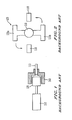
- Portable power tools used for drilling, fastening and the like are expected to be relatively small and light, yet provide high power to perform the functions.
- the tool is typically driven by an electric motor 110.
- the rotational motion of the motor 110 is transmitted to a chuck 160 which holds a tool bit 115 by means of an intermediate mechanism 120.
- the motor 110 is generally small due to restrictions imposed on overall size and weight of the portable power tools. Limited power of the small motor might not be enough to drive the intended load.
- a hammer type of mechanism 120 is introduced to respond to the need to generate high output torque from a small drive.
- the hammer type of mechanism 120 is rotated by the motor 110.
- the hammer type of mechanism 120 includes hammers (120a and 120b).
- the hammer type of mechanism 120 stores the rotational energy of the motor 110 over a large angle of rotation, for example, half turn (180°). Then the hammers (120a and 120b) hit the chuck 160 to create an impact torque over a small angle (for example 10°) of rotation of the chuck 160.
- noise is made when the hammers (120a and 120b) hit the chucks 160.
- GB 713,018 A discloses a tool rotator for a reciprocating hammer, which comprises a hammer which is moved reciprocatingly by magnetic means and which is moved such that it hits an upper end of a tool holder, thereby creating a hammer function by its mechanical impact.
- US 3,150,725 discloses a magnetically operated tool, comprising a hammer which is driven in a rotational way and which is arranged such that it mechanically hits an anvil, thereby realizing a rotational movement by means of these mechanical impacts.
- This object is solved by a power tool according to claim 1 and a method according to claim 8.
- Claims 2 to 7 are related to specifically advantageous embodiments of the power tool according to claim 1.
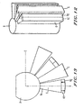
- a portable power tool 100 used for drilling, fastening and the like includes a magnetic impact device 25.
- the magnetic impact device 25 includes an impact generator 2, a motor 10 and a shaft 8 which connects the impact generator 2 and the motor 10.
- the magnetic impact device 25 is configured to generate an impact motion.
- the portable power tool 100 includes, for example, an impact driver and the like.
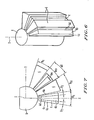
- the impact generator 2 includes at least one hammer 4 and at least one chuck 6.
- the impact generator 2 includes a plurality of hammers 4 and a plurality of chucks 6.
- the hammer 4 is, for example, a solid plate.
- the chuck 6 is a frame which can accommodate the hammer 4 within the frame.
- the hammers 4 are connected to a circumferential surface of the shaft 8, for example, with substantially equal angular space ( ⁇ hs) (see Fig. 7).
- the shaft 8 is rotatable around an axis Z of the shaft 8 which is perpendicular to an X-Y plane.
- the impact generator 2 includes, for example, nine hammers 4.
- the hammer 4 has both side faces (4a) which extend from the axis Z and are substantially perpendicular to the X-Y plane.
- the hammer 4 has, for example, a substantially fan-shaped cross section taken along the X-Y plane.
- a central angle ( ⁇ h) of the hammer 4 between the side faces (4a) is, for example, about 20°.
- the angular space ( ⁇ hs) between the hammers 4 is, for example, substantially equal to the central angle ( ⁇ h) of the hammer 4, i.e., about 20°.
- the angular space ( ⁇ hs) between the hammers 4 may be different from the central angle ( ⁇ h) of the hammer 4.
- the shaft 8 is connected to the motor 10. Accordingly, the motor 10 rotates the hammers 4 via the shaft 8.
- the chuck 6 is connected to a tool, for example, a driver 20 to rotate screws by impact rotational force.
- the chucks 6 are provided to be coaxial with the hammers 4 and to be relatively rotatable with respect to the hammers 4 around the shaft 8.
- the chucks 6 are made of soft magnetic material of high permeability.
- the chucks 6 are provided around the shaft 8, for example, with substantially equal angular space.
- the impact generator 2 includes, for example, nine chucks 6. Although the number of the hammers 4 is the same as that of the chucks 6 in the present embodiment, these numbers may be different.
- the chuck 6 is, for example, substantially trapezoidal in a top plan view (see Fig. 5).
- the chuck 6 may have a substantially fan-shaped form in the top plan view.
- a central angle ( ⁇ c) of the chuck 6 is, for example, about 20°.
- the angular space ( ⁇ cs) between the chucks 6 is, for example, substantially equal to the central angle ( ⁇ c) of the chuck 6, i.e., about 20°.
- the angular space ( ⁇ cs) between the chucks 6 may be different from the central angle ( ⁇ c) of the chuck 6.
- the angular space ( ⁇ cs) between the chucks 6 and the central angle ( ⁇ c) of the chuck 6 may be different from the angular space ( ⁇ hs) between the hammers 4 and the central angle ( ⁇ h) of the hammer 4, respectively.
- Figs. 6 and 7 show the impact generator 2. Only two hammers 4 and two chucks 6 are illustrated in order to simplify the drawings.
- the hammer 4 includes first and second yokes (4c and 4d) and a permanent magnet (4b) which is sandwiched between the first and second yokes (4c and 4d).
- the permanent magnet (4b) is connected to the shaft 8 and radially extends from the shaft 8.
- the first and second yokes (4c and 4d) are made of soft magnetic material of high permeability.
- the function of the first and second yokes (4c and 4d) is to collect the magnetic field emanated by the permanent magnet (4b) and to direct the magnetic field to the chucks 6.
- the outer circumferences of the permanent magnet (4b) and the first and second yokes (4c and 4d) are arc-shaped in the X-Y plane.
- the central angle ( ⁇ m) of the arc of the permanent magnet (4b) is, for example, about 10°.
- the central angle ( ⁇ y) of the arc of each of the first and second yokes (4c and 4d) is, for example, about 5°.
- the cross section of the hammer 4 taken along the plane including the axis Z may be substantially rectangular.
- the air gap between the hammer 4 and the chuck 6 is, for example, about 0.25 mm. It is preferable that the air gap is as small as possible.
- a magnetization direction of the permanent magnet (4b) is along the circumferential direction of the shaft 8.
- the hammers 4 are provided such that N-pole and S-pole of the permanent magnet (4b) are alternatively positioned.
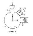
- Figs. 8, 9(a)-9(c) and 10(a)-10(c) the operation of the magnetic impact device 25 will be explained.
- hammers 41 and 42 among the hammers 4 and chucks 61 and 62 among the chucks 6 are illustrated to simplify the explanation.
- Figs. 10(a)-10(c) shows a simple mechanical analogy of a ball rolling on a curved surface under the influence of gravity.
- the shifting angle ( ⁇ ) (see Fig. 7) formed between the hammer 42 and the chuck 62 is equal to zero. Namely, the chuck 62 substantially completely accommodates the hammer 42 therein.
- the hammer 42 is midway between two consecutive chucks (61 and 62), wherein "n" represents the number of the hammers or the chucks. At this angle the hammer 42 is at unstable equilibrium. Referring to Fig. 10(c), this situation is similar to the situation in which the ball locates at the top of the curved surface. The potential energy of the ball is maximum.
- a small rotation of the hammer 42 in the clockwise direction makes the hammer 42 get attracted magnetically towards the forward chuck 61.
- the hammer 42 accelerates towards the forward chuck 61, i.e., the next stable equilibrium point, dissipating the stored magnetic energy.
- the hammer 42 goes past the forward chuck 61 (the equilibrium point) and exerts a momentary attractive torque on the forward chuck 61 in the clockwise direction.
- This torque is the impact torque generated magnetically in a non-contact manner. Namely, magnetic energy stored while the hammer 42 is trying to escape the attraction of one chuck 62 is used to generate an impact to the next chuck 61.
- the magnetic field necessary for generating the impact is provided by the permanent magnet.
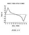
- Magnetic energy stored and transmitted for generating the impact corresponds to the change of internal energy of the permanent magnet.
- Minimum internal energy of the permanent magnet is zero.
- Maximum internal energy of the permanent magnet is limited by the remanence (Br) and volume fraction of the permanent magnet in the total volume. Given those parameters, one can estimate maximum magnetic energy variation available for generating an impact.
- the remanence (Br) is about 1.2 tesla
- volume fraction of the magnet is about 0.18.
- the estimated maximum energy variation is about 4.4J.
- Torque increases as the radius at which the magnetic interaction between the hammers 4 and the chucks 6 occurs.
- a radius of the hammer 4 is determined as large as possible (for example, 27.5mm) within the limits like maximum radius (30mm) of the device and maximum magnetic field allowable in the soft magnetic material (about 2 tesla).
- impact noise associated with mechanical hammer impact device may reduce.
- the permanent magnet (4b) is connected to the shaft 8 and radially extends from the shaft 8. Further, as shown in Fig. 8, a magnetization direction of the permanent magnet (4b) is along the circumferential direction of the shaft 8.
- the hammer 4 may include a yoke (4e) and first and second permanent magnets (4f and 4g). Referring to Figs. 12 and 13, the yoke (4e) is connected to the shaft 8.
- the first and second permanent magnets (4f and 4g) are provided on the outer circumferential surface of the yoke (4e) such that the first permanent magnet (4f) is positioned forward with respect to the second permanent magnet (4g) in the clockwise rotational direction.
- the first and second permanent magnets (4f and 4g) are magnetized in radial direction.
- the magnetization direction of the first permanent magnet (4f) is opposite to that of the second permanent magnet (4g) (see Fig. 13).
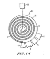
- Fig. 14 is a top plan view of a portion of the magnetic impact device 25 according to another embodiment of the present invention.
- the shaft 8 is coaxially provided in a cylindrical shaft 80.
- the outer circumference of the shaft 8 is connected to the cylindrical shaft 80 via a mechanical spring 12.
- the hammers 4 are connected to an outer circumferential surface of the cylindrical shaft 80, for example, with substantially equal angular space.
- the chucks 6 are provided to be coaxial with the hammers 4 and to be relatively rotatable with respect to the hammers 4 around the cylindrical shaft 80.
- the electric motor 10 rotates the hammers 4.
- this electric motor 10 is small. Since such a motor generates relatively low torque, it would be difficult to store enough energy in the air gap over the shifting angle ( ⁇ ) of 180°/n.
- the energy to be stored in the air gap may increase, because the mechanical spring 12 is provided between the motor 10 and the hammer 4 as shown in Fig. 14. Namely, the spring 12 elastically deforms to store energy therein when the motor rotates the shaft 8. The torque of the shaft 8 is amplified and transmitted to the cylindrical shaft 80 via the spring 12. Accordingly, even though the output torque of the motor 10 is small, the motor 10 can rotate the hammers 4 against the magnetic force between the hammers 4 and the chucks 6.
- the spring 12 is chosen such that motor energy stored over a large angle of rotation of the motor (for example 180°) is equal to the peak energy stored over the small angle of 180°/n (for example 20°).
- the chuck 6 has a frame shape inside of which the hammer 4 passes through.
- the hammer may have a frame shape inside of which the chuck passes through.
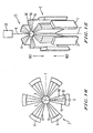
- Figs. 15 and 16 show a magnetic impact device 25 according to yet another embodiment of the present invention.
- the impact generator 2 includes a plurality of hammers 4 and a plurality of chucks 6.
- the hammers 4 are, for example, similar to hammers shown in Figs. 4 and 5.
- the hammers 4 are connected to a circumferential surface of the shaft 8, for example, with substantially equal angular space.
- the shaft 8 is connected to a linear motor 10 and linearly movable along the axis Z of the shaft 8.
- the impact generator 2 includes, for example, six hammers 4.
- the chucks 6 are provided to be coaxial with the hammers 4 and to be relatively linearly movable along the axis Z.
- the chucks 6 are provided around the shaft 8 facing the corresponding hammers 4 , respectively.
- the impact generator 2 includes, for example, six chucks 6. Although the number of the hammers 4 is the same as that of the chucks 6 in the present embodiment, these numbers may be different.
- a first moving direction (MD1) along the axis Z.
- the hammers 4 go past the chucks 6 (the equilibrium point) and exerts a momentary attractive force on the chucks 6 in the first moving direction (MD1).
- This force is the linear impact force generated magnetically in a non-contact manner. Namely, magnetic energy stored while the hammers 4 are trying to escape the attraction of the chucks 6 is used to generate an impact to the chucks 6.
- linear impact motion may be generated while the impact noise reduces.
- the permanent magnet is provided to the hammers 4.
- the permanent magnet may be provided to the chucks 6 and the magnetic material is provided to the hammers 4. Further, the permanent magnet may be provided to both the chucks 6 and the hammers 4.
Landscapes
- Engineering & Computer Science (AREA)
- Mechanical Engineering (AREA)
- Power Engineering (AREA)
- Percussive Tools And Related Accessories (AREA)
- Apparatuses For Generation Of Mechanical Vibrations (AREA)
- Road Signs Or Road Markings (AREA)
- Spinning Or Twisting Of Yarns (AREA)
- Magnetic Resonance Imaging Apparatus (AREA)
Claims (8)
- Kraftbetriebenes Werkzeug mit einer magnetischen Schlagvorrichtung, umfassend:wenigstens einen Rahmen (6), welcher wenigstens einen Hammer (4) aufnehmen kann, wobei der wenigstens eine Hammer (4) relativ bezüglich des wenigstens einen Rahmens (6) beweglich ist, wobei einer von dem wenigstens einen Hammer (4) unddem wenigstens einen Rahmen (6) wenigstens einen Magneten aufweist, wobei ein weiterer von dem wenigstens einen Hammer (4) und dem wenigstens einen Rahmen (6) wenigstens einen Magneten oder ein magnetisches Material aufweist; und gekennzeichnet durcheine Antriebseinheit (10), welche so konfiguriert ist, daß sie den wenigstens einen Hammer (4) relativ zu dem wenigstens einen Rahmen (6) gegen eine Last des wenigstens einen Rahmens (6) drehen kann, so daß magnetische Energie angesammelt wird, und so daß der wenigstens eine Hammer (4) in Richtung auf wenigstens einen Rahmen (6) beschleunigt wird, nachdem er eine maximale Energie erreicht hat, um somit auf magnetische Weise ein Schlag-Drehmoment an dem wenigstens einen Rahmen (6) berührungslos zu erzeugen.
- Kraftbetriebenes Werkzeug nach Anspruch 1, wobei der wenigstens eine Hammer (4) umfaßt:wenigstens ein Joch, welches aus magnetischem Material hergestellt ist und an welchem der wenigstens eine Magnet vorgesehen ist.
- Kraftbetriebenes Werkzeug nach Anspruch 2, wobei die magnetische Schlagvorrichtung ein erstes und zweites Joch umfaßt, welche den wenigstens einen Magneten zwischen sich angeordnet aufweisen.
- Kraftbetriebenes Werkzeug nach Anspruch 1, wobei der wenigstens eine Hammer (4) mit einer Welle verbunden ist, und wobei die Antriebseinheit (10) dazu konfiguriert ist, den wenigstens einen Hammer um die Welle zu drehen.
- Kraftbetriebenes Werkzeug nach Anspruch 4, welches ferner umfaßt:eine zylindrische Welle, in der die Welle koaxial vorgesehen ist, wobei der wenigstens eine Hammer (4) mit einer äußeren, umlaufenden Oberfläche der zylindrischen Welle verbunden ist; undeine Feder, welche die zylindrische Welle und die Welle verbindet.
- Kraftbetriebenes Werkzeug nach Anspruch 1, wobei der wenigstens eine Hammer (4) mit einer Welle verbunden ist, und wobei die Antriebseinheit (10) derart konfiguriert ist, den wenigstens einen Hammer (4) entlang einer Achse der Welle linear zu bewegen.
- Kraftbetriebenes Werkzeug nach Anspruch 5, wobei die Feder konfiguriert ist, um Motorenergie zu speichern, welche im wesentlichen gleich einer magnetischen Spitzenenergie ist, die in dem Magneten gespeichert ist.
- Verfahren, um auf magnetische Weise einen Schlag auf einen Rahmen (6) eines kraftbetriebenen Werkzeugs zu erzeugen, welches umfaßt:Bereitstellen wenigstens eines Rahmens (6), welcher wenigstens einen Hammer (4) aufnehmen kann;Bereitstellen des wenigstens einen Hammers (4);Versehen eines von dem wenigstens einen Hammer (4) und dem wenigstens einen Rahmen (6) mit wenigstens einem Magneten;Versehen eines weiteren von dem wenigstens einen Hammer (4) und dem wenigstens einen Rahmen (6) mit wenigstens einem Magneten oder magnetischen Material; und welches gekennzeichnet ist durchDrehen des wenigstens einen Hammers (4) relativ zu dem wenigstens einen Rahmen (6) gegen eine Last des wenigstens einen Rahmens (6), so daß magnetische Energie angesammelt wird, und so daß der wenigstens eine Hammer in Richtung auf wenigstens einen Rahmen (6) beschleunigt wird, nachdem er eine maximale Energie erreicht hat, um somit auf magnetische Weise ein Schlag-Drehmoment an dem wenigstens einen Rahmen (6) berührungslos zu erzeugen.
Applications Claiming Priority (3)
| Application Number | Priority Date | Filing Date | Title |
|---|---|---|---|
| US211539 | 2002-08-05 | ||
| US10/211,539 US6695070B1 (en) | 2002-08-05 | 2002-08-05 | Magnetic impact device and method for magnetically generating impact motion |
| PCT/JP2003/009618 WO2004012910A2 (en) | 2002-08-05 | 2003-07-29 | Magnetic impact device and method for magnetically generating impact motion |
Publications (2)
| Publication Number | Publication Date |
|---|---|
| EP1461186A2 EP1461186A2 (de) | 2004-09-29 |
| EP1461186B1 true EP1461186B1 (de) | 2006-09-06 |
Family
ID=31187594
Family Applications (1)
| Application Number | Title | Priority Date | Filing Date |
|---|---|---|---|
| EP03766658A Expired - Lifetime EP1461186B1 (de) | 2002-08-05 | 2003-07-29 | Magnetische schlagvorrichtung und verfahren zur magnetischen erzeugung von schlagbewegung |
Country Status (7)
| Country | Link |
|---|---|
| US (1) | US6695070B1 (de) |
| EP (1) | EP1461186B1 (de) |
| JP (1) | JP2005523175A (de) |
| CN (1) | CN100336288C (de) |
| AT (1) | ATE339028T1 (de) |
| DE (1) | DE60308140T2 (de) |
| WO (1) | WO2004012910A2 (de) |
Families Citing this family (9)
| Publication number | Priority date | Publication date | Assignee | Title |
|---|---|---|---|---|
| JP2004291138A (ja) * | 2003-03-26 | 2004-10-21 | Matsushita Electric Works Ltd | 磁気インパクト工具 |
| JP4326452B2 (ja) * | 2004-10-26 | 2009-09-09 | パナソニック電工株式会社 | 衝撃工具 |
| JP4513128B2 (ja) * | 2004-12-28 | 2010-07-28 | 日立工機株式会社 | パルストルク発生装置及び動力工具 |
| US20070261868A1 (en) * | 2006-05-12 | 2007-11-15 | Gross James R | Magnetic torque-limiting device and method |
| JP4834188B1 (ja) * | 2011-05-27 | 2011-12-14 | 有志 米田 | 衝撃発生装置 |
| DE102011085820B4 (de) * | 2011-11-07 | 2013-07-25 | Hilti Aktiengesellschaft | Handwerkzeugmaschine |
| DE102011088287A1 (de) | 2011-11-07 | 2013-05-08 | Hilti Aktiengesellschaft | Schlagwerk |
| US9597784B2 (en) * | 2013-08-12 | 2017-03-21 | Ingersoll-Rand Company | Impact tools |
| JP6814979B2 (ja) * | 2017-02-24 | 2021-01-20 | パナソニックIpマネジメント株式会社 | 電動工具 |
Family Cites Families (14)
| Publication number | Priority date | Publication date | Assignee | Title |
|---|---|---|---|---|
| US519662A (en) * | 1894-05-08 | Electromagnetic tool | ||
| US2635854A (en) * | 1950-09-12 | 1953-04-21 | Syntron Co | Tool rotator for reciprocating hammers |
| US2861778A (en) * | 1954-10-07 | 1958-11-25 | Syntron Co | Electromagnetic reciprocating hammer |
| US2949909A (en) * | 1957-05-22 | 1960-08-23 | Macchioni Pietro Aurelio | Electromagnetic hammer |
| US3150725A (en) * | 1961-07-13 | 1964-09-29 | Ingersoll Rand Co | Magnetically operated tool |
| US3811313A (en) * | 1971-04-12 | 1974-05-21 | Boeing Co | Electromagnetic high energy impact apparatus |
| FR2499647B1 (fr) * | 1981-02-06 | 1989-03-03 | Nova Scotia Res Found | Perfectionnements aux accouplements magnetiques hermetiques |
| FR2514049A1 (fr) * | 1981-10-02 | 1983-04-08 | Martelec | Dispositif de foncage et d'arrachement pour pieux, tubes, palplanches, tiges, etc. |
| JPS6224979A (ja) * | 1985-07-25 | 1987-02-02 | 松下電工株式会社 | 振動ドリル |
| JP2640124B2 (ja) * | 1988-06-17 | 1997-08-13 | 株式会社芝浦製作所 | 衝撃工具 |
| US5376862A (en) * | 1993-01-28 | 1994-12-27 | Applied Materials, Inc. | Dual coaxial magnetic couplers for vacuum chamber robot assembly |
| US5497555A (en) * | 1994-12-19 | 1996-03-12 | Averbukh; Moshe | Electromagnetic percussion device |
| FR2766028A1 (fr) * | 1997-07-08 | 1999-01-15 | Ensmse | Dispositif a fort couple d'accouplements magnetiques synchrones a entrefer cylindrique |
| DE19855750A1 (de) * | 1998-12-03 | 2000-06-08 | Hilti Ag | Handgeführtes Bohr- und/oder Meisselgerät |
-
2002
- 2002-08-05 US US10/211,539 patent/US6695070B1/en not_active Expired - Fee Related
-
2003
- 2003-07-29 JP JP2004525796A patent/JP2005523175A/ja active Pending
- 2003-07-29 EP EP03766658A patent/EP1461186B1/de not_active Expired - Lifetime
- 2003-07-29 CN CNB038014149A patent/CN100336288C/zh not_active Expired - Fee Related
- 2003-07-29 WO PCT/JP2003/009618 patent/WO2004012910A2/en active IP Right Grant
- 2003-07-29 AT AT03766658T patent/ATE339028T1/de not_active IP Right Cessation
- 2003-07-29 DE DE60308140T patent/DE60308140T2/de not_active Expired - Lifetime
Also Published As
| Publication number | Publication date |
|---|---|
| WO2004012910A3 (en) | 2004-07-29 |
| CN100336288C (zh) | 2007-09-05 |
| JP2005523175A (ja) | 2005-08-04 |
| US20040020667A1 (en) | 2004-02-05 |
| US6695070B1 (en) | 2004-02-24 |
| CN1606824A (zh) | 2005-04-13 |
| ATE339028T1 (de) | 2006-09-15 |
| EP1461186A2 (de) | 2004-09-29 |
| DE60308140T2 (de) | 2007-01-04 |
| WO2004012910A2 (en) | 2004-02-12 |
| DE60308140D1 (de) | 2006-10-19 |
Similar Documents
| Publication | Publication Date | Title |
|---|---|---|
| WO2003025394A3 (en) | Motor assembly allowing output in multiple degrees of freedom | |
| WO1987004576A1 (en) | Magnetic rotary device | |
| EP1461186B1 (de) | Magnetische schlagvorrichtung und verfahren zur magnetischen erzeugung von schlagbewegung | |
| KR100760846B1 (ko) | 강성 발생 장치 및 이를 구비하는 로봇 머니퓰레이터의조인트 | |
| US20060119201A1 (en) | Magnetic transmission | |
| US8508089B2 (en) | Magnetic drive motor assembly and associated methods | |
| JP2006204003A (ja) | 振動型リニアアクチュエータ及びこれを用いた電動歯ブラシ | |
| CN103189165A (zh) | 工具机制动装置 | |
| JP2009509482A (ja) | 磁気モーター | |
| US3150725A (en) | Magnetically operated tool | |
| JP5584559B2 (ja) | インパクト回転工具 | |
| JP2005523175A5 (de) | ||
| JP2008054374A (ja) | 磁気駆動機構 | |
| KR200187408Y1 (ko) | 모터의 회전자 보조 구동 장치 | |
| KR101029610B1 (ko) | 모터 | |
| KR20080079562A (ko) | 영구자석을 이용한 회전동력에너지 발생장치 | |
| JP2020129932A (ja) | 回転装置及び発電システム | |
| JP2001190058A (ja) | 磁力回転装置 | |
| JP2005094954A (ja) | 運動エネルギーの加速増幅装置 | |
| US8546981B2 (en) | Actuator | |
| JP3783798B2 (ja) | 電磁式打撃装置 | |
| JP2002325426A (ja) | 動力装置 | |
| JP2005033973A (ja) | 磁石及び電磁石による駆動力発生装置及びこれを組み込んだ回転電機や駆動装置 | |
| JPH11262239A (ja) | 磁力回転装置 | |
| JP2000060104A (ja) | 動力装置 |
Legal Events
| Date | Code | Title | Description |
|---|---|---|---|
| PUAI | Public reference made under article 153(3) epc to a published international application that has entered the european phase |
Free format text: ORIGINAL CODE: 0009012 |
|
| 17P | Request for examination filed |
Effective date: 20040421 |
|
| AK | Designated contracting states |
Kind code of ref document: A2 Designated state(s): AT BE BG CH CY CZ DE DK EE ES FI FR GB GR HU IE IT LI LU MC NL PT RO SE SI SK TR |
|
| AX | Request for extension of the european patent |
Extension state: AL LT LV MK |
|
| RIC1 | Information provided on ipc code assigned before grant |
Ipc: 7H 02K 49/10 A |
|
| 17Q | First examination report despatched |
Effective date: 20050120 |
|
| DAX | Request for extension of the european patent (deleted) | ||
| GRAP | Despatch of communication of intention to grant a patent |
Free format text: ORIGINAL CODE: EPIDOSNIGR1 |
|
| GRAS | Grant fee paid |
Free format text: ORIGINAL CODE: EPIDOSNIGR3 |
|
| GRAA | (expected) grant |
Free format text: ORIGINAL CODE: 0009210 |
|
| AK | Designated contracting states |
Kind code of ref document: B1 Designated state(s): AT BE BG CH CY CZ DE DK EE ES FI FR GB GR HU IE IT LI LU MC NL PT RO SE SI SK TR |
|
| PG25 | Lapsed in a contracting state [announced via postgrant information from national office to epo] |
Ref country code: IT Free format text: LAPSE BECAUSE OF FAILURE TO SUBMIT A TRANSLATION OF THE DESCRIPTION OR TO PAY THE FEE WITHIN THE PRESCRIBED TIME-LIMIT;WARNING: LAPSES OF ITALIAN PATENTS WITH EFFECTIVE DATE BEFORE 2007 MAY HAVE OCCURRED AT ANY TIME BEFORE 2007. THE CORRECT EFFECTIVE DATE MAY BE DIFFERENT FROM THE ONE RECORDED. Effective date: 20060906 Ref country code: LI Free format text: LAPSE BECAUSE OF FAILURE TO SUBMIT A TRANSLATION OF THE DESCRIPTION OR TO PAY THE FEE WITHIN THE PRESCRIBED TIME-LIMIT Effective date: 20060906 Ref country code: RO Free format text: LAPSE BECAUSE OF FAILURE TO SUBMIT A TRANSLATION OF THE DESCRIPTION OR TO PAY THE FEE WITHIN THE PRESCRIBED TIME-LIMIT Effective date: 20060906 Ref country code: CH Free format text: LAPSE BECAUSE OF FAILURE TO SUBMIT A TRANSLATION OF THE DESCRIPTION OR TO PAY THE FEE WITHIN THE PRESCRIBED TIME-LIMIT Effective date: 20060906 Ref country code: SK Free format text: LAPSE BECAUSE OF FAILURE TO SUBMIT A TRANSLATION OF THE DESCRIPTION OR TO PAY THE FEE WITHIN THE PRESCRIBED TIME-LIMIT Effective date: 20060906 Ref country code: CZ Free format text: LAPSE BECAUSE OF FAILURE TO SUBMIT A TRANSLATION OF THE DESCRIPTION OR TO PAY THE FEE WITHIN THE PRESCRIBED TIME-LIMIT Effective date: 20060906 Ref country code: AT Free format text: LAPSE BECAUSE OF FAILURE TO SUBMIT A TRANSLATION OF THE DESCRIPTION OR TO PAY THE FEE WITHIN THE PRESCRIBED TIME-LIMIT Effective date: 20060906 Ref country code: SI Free format text: LAPSE BECAUSE OF FAILURE TO SUBMIT A TRANSLATION OF THE DESCRIPTION OR TO PAY THE FEE WITHIN THE PRESCRIBED TIME-LIMIT Effective date: 20060906 Ref country code: NL Free format text: LAPSE BECAUSE OF FAILURE TO SUBMIT A TRANSLATION OF THE DESCRIPTION OR TO PAY THE FEE WITHIN THE PRESCRIBED TIME-LIMIT Effective date: 20060906 Ref country code: BE Free format text: LAPSE BECAUSE OF FAILURE TO SUBMIT A TRANSLATION OF THE DESCRIPTION OR TO PAY THE FEE WITHIN THE PRESCRIBED TIME-LIMIT Effective date: 20060906 |
|
| REG | Reference to a national code |
Ref country code: GB Ref legal event code: FG4D |
|
| REG | Reference to a national code |
Ref country code: CH Ref legal event code: EP |
|
| REG | Reference to a national code |
Ref country code: IE Ref legal event code: FG4D |
|
| REF | Corresponds to: |
Ref document number: 60308140 Country of ref document: DE Date of ref document: 20061019 Kind code of ref document: P |
|
| PG25 | Lapsed in a contracting state [announced via postgrant information from national office to epo] |
Ref country code: BG Free format text: LAPSE BECAUSE OF FAILURE TO SUBMIT A TRANSLATION OF THE DESCRIPTION OR TO PAY THE FEE WITHIN THE PRESCRIBED TIME-LIMIT Effective date: 20061206 Ref country code: DK Free format text: LAPSE BECAUSE OF FAILURE TO SUBMIT A TRANSLATION OF THE DESCRIPTION OR TO PAY THE FEE WITHIN THE PRESCRIBED TIME-LIMIT Effective date: 20061206 |
|
| PG25 | Lapsed in a contracting state [announced via postgrant information from national office to epo] |
Ref country code: ES Free format text: LAPSE BECAUSE OF FAILURE TO SUBMIT A TRANSLATION OF THE DESCRIPTION OR TO PAY THE FEE WITHIN THE PRESCRIBED TIME-LIMIT Effective date: 20061217 |
|
| REG | Reference to a national code |
Ref country code: SE Ref legal event code: TRGR |
|
| PG25 | Lapsed in a contracting state [announced via postgrant information from national office to epo] |
Ref country code: PT Free format text: LAPSE BECAUSE OF FAILURE TO SUBMIT A TRANSLATION OF THE DESCRIPTION OR TO PAY THE FEE WITHIN THE PRESCRIBED TIME-LIMIT Effective date: 20070219 |
|
| NLV1 | Nl: lapsed or annulled due to failure to fulfill the requirements of art. 29p and 29m of the patents act | ||
| REG | Reference to a national code |
Ref country code: CH Ref legal event code: PL |
|
| EN | Fr: translation not filed | ||
| PLBE | No opposition filed within time limit |
Free format text: ORIGINAL CODE: 0009261 |
|
| STAA | Information on the status of an ep patent application or granted ep patent |
Free format text: STATUS: NO OPPOSITION FILED WITHIN TIME LIMIT |
|
| 26N | No opposition filed |
Effective date: 20070607 |
|
| PG25 | Lapsed in a contracting state [announced via postgrant information from national office to epo] |
Ref country code: GR Free format text: LAPSE BECAUSE OF FAILURE TO SUBMIT A TRANSLATION OF THE DESCRIPTION OR TO PAY THE FEE WITHIN THE PRESCRIBED TIME-LIMIT Effective date: 20061207 Ref country code: MC Free format text: LAPSE BECAUSE OF NON-PAYMENT OF DUE FEES Effective date: 20070731 Ref country code: FR Free format text: LAPSE BECAUSE OF FAILURE TO SUBMIT A TRANSLATION OF THE DESCRIPTION OR TO PAY THE FEE WITHIN THE PRESCRIBED TIME-LIMIT Effective date: 20070511 |
|
| PG25 | Lapsed in a contracting state [announced via postgrant information from national office to epo] |
Ref country code: EE Free format text: LAPSE BECAUSE OF FAILURE TO SUBMIT A TRANSLATION OF THE DESCRIPTION OR TO PAY THE FEE WITHIN THE PRESCRIBED TIME-LIMIT Effective date: 20060906 |
|
| PG25 | Lapsed in a contracting state [announced via postgrant information from national office to epo] |
Ref country code: IE Free format text: LAPSE BECAUSE OF NON-PAYMENT OF DUE FEES Effective date: 20070730 |
|
| PG25 | Lapsed in a contracting state [announced via postgrant information from national office to epo] |
Ref country code: FR Free format text: LAPSE BECAUSE OF FAILURE TO SUBMIT A TRANSLATION OF THE DESCRIPTION OR TO PAY THE FEE WITHIN THE PRESCRIBED TIME-LIMIT Effective date: 20060906 |
|
| PG25 | Lapsed in a contracting state [announced via postgrant information from national office to epo] |
Ref country code: LU Free format text: LAPSE BECAUSE OF NON-PAYMENT OF DUE FEES Effective date: 20070729 Ref country code: CY Free format text: LAPSE BECAUSE OF FAILURE TO SUBMIT A TRANSLATION OF THE DESCRIPTION OR TO PAY THE FEE WITHIN THE PRESCRIBED TIME-LIMIT Effective date: 20060906 |
|
| PG25 | Lapsed in a contracting state [announced via postgrant information from national office to epo] |
Ref country code: TR Free format text: LAPSE BECAUSE OF FAILURE TO SUBMIT A TRANSLATION OF THE DESCRIPTION OR TO PAY THE FEE WITHIN THE PRESCRIBED TIME-LIMIT Effective date: 20060906 Ref country code: HU Free format text: LAPSE BECAUSE OF FAILURE TO SUBMIT A TRANSLATION OF THE DESCRIPTION OR TO PAY THE FEE WITHIN THE PRESCRIBED TIME-LIMIT Effective date: 20070307 |
|
| PGFP | Annual fee paid to national office [announced via postgrant information from national office to epo] |
Ref country code: FI Payment date: 20140710 Year of fee payment: 12 |
|
| PGFP | Annual fee paid to national office [announced via postgrant information from national office to epo] |
Ref country code: SE Payment date: 20140711 Year of fee payment: 12 |
|
| PGFP | Annual fee paid to national office [announced via postgrant information from national office to epo] |
Ref country code: IT Payment date: 20140714 Year of fee payment: 12 |
|
| PGFP | Annual fee paid to national office [announced via postgrant information from national office to epo] |
Ref country code: GB Payment date: 20150729 Year of fee payment: 13 Ref country code: DE Payment date: 20150722 Year of fee payment: 13 |
|
| REG | Reference to a national code |
Ref country code: SE Ref legal event code: EUG |
|
| PG25 | Lapsed in a contracting state [announced via postgrant information from national office to epo] |
Ref country code: IT Free format text: LAPSE BECAUSE OF NON-PAYMENT OF DUE FEES Effective date: 20150729 |
|
| PG25 | Lapsed in a contracting state [announced via postgrant information from national office to epo] |
Ref country code: SE Free format text: LAPSE BECAUSE OF NON-PAYMENT OF DUE FEES Effective date: 20150730 Ref country code: FI Free format text: LAPSE BECAUSE OF NON-PAYMENT OF DUE FEES Effective date: 20150729 |
|
| REG | Reference to a national code |
Ref country code: DE Ref legal event code: R119 Ref document number: 60308140 Country of ref document: DE |
|
| GBPC | Gb: european patent ceased through non-payment of renewal fee |
Effective date: 20160729 |
|
| PG25 | Lapsed in a contracting state [announced via postgrant information from national office to epo] |
Ref country code: DE Free format text: LAPSE BECAUSE OF NON-PAYMENT OF DUE FEES Effective date: 20170201 |
|
| PG25 | Lapsed in a contracting state [announced via postgrant information from national office to epo] |
Ref country code: GB Free format text: LAPSE BECAUSE OF NON-PAYMENT OF DUE FEES Effective date: 20160729 |