EP1458586B1 - Vorrichtung und verfahren zur regelung der fahrgeschwindigkeit eines fahrzeugs - Google Patents
Vorrichtung und verfahren zur regelung der fahrgeschwindigkeit eines fahrzeugs Download PDFInfo
- Publication number
- EP1458586B1 EP1458586B1 EP02794983A EP02794983A EP1458586B1 EP 1458586 B1 EP1458586 B1 EP 1458586B1 EP 02794983 A EP02794983 A EP 02794983A EP 02794983 A EP02794983 A EP 02794983A EP 1458586 B1 EP1458586 B1 EP 1458586B1
- Authority
- EP
- European Patent Office
- Prior art keywords
- vehicle
- speed
- torque
- electrical machine
- electric machine
- Prior art date
- Legal status (The legal status is an assumption and is not a legal conclusion. Google has not performed a legal analysis and makes no representation as to the accuracy of the status listed.)
- Expired - Lifetime
Links
Images
Classifications
-
- B—PERFORMING OPERATIONS; TRANSPORTING
- B60—VEHICLES IN GENERAL
- B60K—ARRANGEMENT OR MOUNTING OF PROPULSION UNITS OR OF TRANSMISSIONS IN VEHICLES; ARRANGEMENT OR MOUNTING OF PLURAL DIVERSE PRIME-MOVERS IN VEHICLES; AUXILIARY DRIVES FOR VEHICLES; INSTRUMENTATION OR DASHBOARDS FOR VEHICLES; ARRANGEMENTS IN CONNECTION WITH COOLING, AIR INTAKE, GAS EXHAUST OR FUEL SUPPLY OF PROPULSION UNITS IN VEHICLES
- B60K6/00—Arrangement or mounting of plural diverse prime-movers for mutual or common propulsion, e.g. hybrid propulsion systems comprising electric motors and internal combustion engines
- B60K6/20—Arrangement or mounting of plural diverse prime-movers for mutual or common propulsion, e.g. hybrid propulsion systems comprising electric motors and internal combustion engines the prime-movers consisting of electric motors and internal combustion engines, e.g. HEVs
- B60K6/42—Arrangement or mounting of plural diverse prime-movers for mutual or common propulsion, e.g. hybrid propulsion systems comprising electric motors and internal combustion engines the prime-movers consisting of electric motors and internal combustion engines, e.g. HEVs characterised by the architecture of the hybrid electric vehicle
- B60K6/48—Parallel type
- B60K6/485—Motor-assist type
-
- B—PERFORMING OPERATIONS; TRANSPORTING
- B60—VEHICLES IN GENERAL
- B60W—CONJOINT CONTROL OF VEHICLE SUB-UNITS OF DIFFERENT TYPE OR DIFFERENT FUNCTION; CONTROL SYSTEMS SPECIALLY ADAPTED FOR HYBRID VEHICLES; ROAD VEHICLE DRIVE CONTROL SYSTEMS FOR PURPOSES NOT RELATED TO THE CONTROL OF A PARTICULAR SUB-UNIT
- B60W20/00—Control systems specially adapted for hybrid vehicles
- B60W20/10—Controlling the power contribution of each of the prime movers to meet required power demand
-
- B—PERFORMING OPERATIONS; TRANSPORTING
- B60—VEHICLES IN GENERAL
- B60K—ARRANGEMENT OR MOUNTING OF PROPULSION UNITS OR OF TRANSMISSIONS IN VEHICLES; ARRANGEMENT OR MOUNTING OF PLURAL DIVERSE PRIME-MOVERS IN VEHICLES; AUXILIARY DRIVES FOR VEHICLES; INSTRUMENTATION OR DASHBOARDS FOR VEHICLES; ARRANGEMENTS IN CONNECTION WITH COOLING, AIR INTAKE, GAS EXHAUST OR FUEL SUPPLY OF PROPULSION UNITS IN VEHICLES
- B60K31/00—Vehicle fittings, acting on a single sub-unit only, for automatically controlling vehicle speed, i.e. preventing speed from exceeding an arbitrarily established velocity or maintaining speed at a particular velocity, as selected by the vehicle operator
- B60K31/02—Vehicle fittings, acting on a single sub-unit only, for automatically controlling vehicle speed, i.e. preventing speed from exceeding an arbitrarily established velocity or maintaining speed at a particular velocity, as selected by the vehicle operator including electrically actuated servomechanism
- B60K31/04—Vehicle fittings, acting on a single sub-unit only, for automatically controlling vehicle speed, i.e. preventing speed from exceeding an arbitrarily established velocity or maintaining speed at a particular velocity, as selected by the vehicle operator including electrically actuated servomechanism and means for comparing one electrical quantity, e.g. voltage, pulse, waveform, flux, or the like, with another quantity of a like kind, which comparison means is involved in the development of an electrical signal which is fed into the controlling means
- B60K31/042—Vehicle fittings, acting on a single sub-unit only, for automatically controlling vehicle speed, i.e. preventing speed from exceeding an arbitrarily established velocity or maintaining speed at a particular velocity, as selected by the vehicle operator including electrically actuated servomechanism and means for comparing one electrical quantity, e.g. voltage, pulse, waveform, flux, or the like, with another quantity of a like kind, which comparison means is involved in the development of an electrical signal which is fed into the controlling means where at least one electrical quantity is set by the vehicle operator
-
- B—PERFORMING OPERATIONS; TRANSPORTING
- B60—VEHICLES IN GENERAL
- B60K—ARRANGEMENT OR MOUNTING OF PROPULSION UNITS OR OF TRANSMISSIONS IN VEHICLES; ARRANGEMENT OR MOUNTING OF PLURAL DIVERSE PRIME-MOVERS IN VEHICLES; AUXILIARY DRIVES FOR VEHICLES; INSTRUMENTATION OR DASHBOARDS FOR VEHICLES; ARRANGEMENTS IN CONNECTION WITH COOLING, AIR INTAKE, GAS EXHAUST OR FUEL SUPPLY OF PROPULSION UNITS IN VEHICLES
- B60K6/00—Arrangement or mounting of plural diverse prime-movers for mutual or common propulsion, e.g. hybrid propulsion systems comprising electric motors and internal combustion engines
- B60K6/20—Arrangement or mounting of plural diverse prime-movers for mutual or common propulsion, e.g. hybrid propulsion systems comprising electric motors and internal combustion engines the prime-movers consisting of electric motors and internal combustion engines, e.g. HEVs
- B60K6/22—Arrangement or mounting of plural diverse prime-movers for mutual or common propulsion, e.g. hybrid propulsion systems comprising electric motors and internal combustion engines the prime-movers consisting of electric motors and internal combustion engines, e.g. HEVs characterised by apparatus, components or means specially adapted for HEVs
- B60K6/26—Arrangement or mounting of plural diverse prime-movers for mutual or common propulsion, e.g. hybrid propulsion systems comprising electric motors and internal combustion engines the prime-movers consisting of electric motors and internal combustion engines, e.g. HEVs characterised by apparatus, components or means specially adapted for HEVs characterised by the motors or the generators
-
- B—PERFORMING OPERATIONS; TRANSPORTING
- B60—VEHICLES IN GENERAL
- B60W—CONJOINT CONTROL OF VEHICLE SUB-UNITS OF DIFFERENT TYPE OR DIFFERENT FUNCTION; CONTROL SYSTEMS SPECIALLY ADAPTED FOR HYBRID VEHICLES; ROAD VEHICLE DRIVE CONTROL SYSTEMS FOR PURPOSES NOT RELATED TO THE CONTROL OF A PARTICULAR SUB-UNIT
- B60W10/00—Conjoint control of vehicle sub-units of different type or different function
- B60W10/04—Conjoint control of vehicle sub-units of different type or different function including control of propulsion units
- B60W10/06—Conjoint control of vehicle sub-units of different type or different function including control of propulsion units including control of combustion engines
-
- B—PERFORMING OPERATIONS; TRANSPORTING
- B60—VEHICLES IN GENERAL
- B60W—CONJOINT CONTROL OF VEHICLE SUB-UNITS OF DIFFERENT TYPE OR DIFFERENT FUNCTION; CONTROL SYSTEMS SPECIALLY ADAPTED FOR HYBRID VEHICLES; ROAD VEHICLE DRIVE CONTROL SYSTEMS FOR PURPOSES NOT RELATED TO THE CONTROL OF A PARTICULAR SUB-UNIT
- B60W10/00—Conjoint control of vehicle sub-units of different type or different function
- B60W10/04—Conjoint control of vehicle sub-units of different type or different function including control of propulsion units
- B60W10/08—Conjoint control of vehicle sub-units of different type or different function including control of propulsion units including control of electric propulsion units, e.g. motors or generators
-
- B—PERFORMING OPERATIONS; TRANSPORTING
- B60—VEHICLES IN GENERAL
- B60W—CONJOINT CONTROL OF VEHICLE SUB-UNITS OF DIFFERENT TYPE OR DIFFERENT FUNCTION; CONTROL SYSTEMS SPECIALLY ADAPTED FOR HYBRID VEHICLES; ROAD VEHICLE DRIVE CONTROL SYSTEMS FOR PURPOSES NOT RELATED TO THE CONTROL OF A PARTICULAR SUB-UNIT
- B60W10/00—Conjoint control of vehicle sub-units of different type or different function
- B60W10/18—Conjoint control of vehicle sub-units of different type or different function including control of braking systems
-
- B—PERFORMING OPERATIONS; TRANSPORTING
- B60—VEHICLES IN GENERAL
- B60W—CONJOINT CONTROL OF VEHICLE SUB-UNITS OF DIFFERENT TYPE OR DIFFERENT FUNCTION; CONTROL SYSTEMS SPECIALLY ADAPTED FOR HYBRID VEHICLES; ROAD VEHICLE DRIVE CONTROL SYSTEMS FOR PURPOSES NOT RELATED TO THE CONTROL OF A PARTICULAR SUB-UNIT
- B60W20/00—Control systems specially adapted for hybrid vehicles
-
- B—PERFORMING OPERATIONS; TRANSPORTING
- B60—VEHICLES IN GENERAL
- B60W—CONJOINT CONTROL OF VEHICLE SUB-UNITS OF DIFFERENT TYPE OR DIFFERENT FUNCTION; CONTROL SYSTEMS SPECIALLY ADAPTED FOR HYBRID VEHICLES; ROAD VEHICLE DRIVE CONTROL SYSTEMS FOR PURPOSES NOT RELATED TO THE CONTROL OF A PARTICULAR SUB-UNIT
- B60W2520/00—Input parameters relating to overall vehicle dynamics
- B60W2520/10—Longitudinal speed
-
- B—PERFORMING OPERATIONS; TRANSPORTING
- B60—VEHICLES IN GENERAL
- B60W—CONJOINT CONTROL OF VEHICLE SUB-UNITS OF DIFFERENT TYPE OR DIFFERENT FUNCTION; CONTROL SYSTEMS SPECIALLY ADAPTED FOR HYBRID VEHICLES; ROAD VEHICLE DRIVE CONTROL SYSTEMS FOR PURPOSES NOT RELATED TO THE CONTROL OF A PARTICULAR SUB-UNIT
- B60W2710/00—Output or target parameters relating to a particular sub-units
- B60W2710/06—Combustion engines, Gas turbines
- B60W2710/0666—Engine torque
-
- B—PERFORMING OPERATIONS; TRANSPORTING
- B60—VEHICLES IN GENERAL
- B60W—CONJOINT CONTROL OF VEHICLE SUB-UNITS OF DIFFERENT TYPE OR DIFFERENT FUNCTION; CONTROL SYSTEMS SPECIALLY ADAPTED FOR HYBRID VEHICLES; ROAD VEHICLE DRIVE CONTROL SYSTEMS FOR PURPOSES NOT RELATED TO THE CONTROL OF A PARTICULAR SUB-UNIT
- B60W2720/00—Output or target parameters relating to overall vehicle dynamics
- B60W2720/10—Longitudinal speed
-
- Y—GENERAL TAGGING OF NEW TECHNOLOGICAL DEVELOPMENTS; GENERAL TAGGING OF CROSS-SECTIONAL TECHNOLOGIES SPANNING OVER SEVERAL SECTIONS OF THE IPC; TECHNICAL SUBJECTS COVERED BY FORMER USPC CROSS-REFERENCE ART COLLECTIONS [XRACs] AND DIGESTS
- Y02—TECHNOLOGIES OR APPLICATIONS FOR MITIGATION OR ADAPTATION AGAINST CLIMATE CHANGE
- Y02T—CLIMATE CHANGE MITIGATION TECHNOLOGIES RELATED TO TRANSPORTATION
- Y02T10/00—Road transport of goods or passengers
- Y02T10/60—Other road transportation technologies with climate change mitigation effect
- Y02T10/62—Hybrid vehicles
-
- Y—GENERAL TAGGING OF NEW TECHNOLOGICAL DEVELOPMENTS; GENERAL TAGGING OF CROSS-SECTIONAL TECHNOLOGIES SPANNING OVER SEVERAL SECTIONS OF THE IPC; TECHNICAL SUBJECTS COVERED BY FORMER USPC CROSS-REFERENCE ART COLLECTIONS [XRACs] AND DIGESTS
- Y02—TECHNOLOGIES OR APPLICATIONS FOR MITIGATION OR ADAPTATION AGAINST CLIMATE CHANGE
- Y02T—CLIMATE CHANGE MITIGATION TECHNOLOGIES RELATED TO TRANSPORTATION
- Y02T10/00—Road transport of goods or passengers
- Y02T10/60—Other road transportation technologies with climate change mitigation effect
- Y02T10/72—Electric energy management in electromobility
-
- Y—GENERAL TAGGING OF NEW TECHNOLOGICAL DEVELOPMENTS; GENERAL TAGGING OF CROSS-SECTIONAL TECHNOLOGIES SPANNING OVER SEVERAL SECTIONS OF THE IPC; TECHNICAL SUBJECTS COVERED BY FORMER USPC CROSS-REFERENCE ART COLLECTIONS [XRACs] AND DIGESTS
- Y10—TECHNICAL SUBJECTS COVERED BY FORMER USPC
- Y10S—TECHNICAL SUBJECTS COVERED BY FORMER USPC CROSS-REFERENCE ART COLLECTIONS [XRACs] AND DIGESTS
- Y10S903/00—Hybrid electric vehicles, HEVS
- Y10S903/902—Prime movers comprising electrical and internal combustion motors
- Y10S903/903—Prime movers comprising electrical and internal combustion motors having energy storing means, e.g. battery, capacitor
- Y10S903/904—Component specially adapted for hev
- Y10S903/907—Electricity storage, e.g. battery, capacitor
-
- Y—GENERAL TAGGING OF NEW TECHNOLOGICAL DEVELOPMENTS; GENERAL TAGGING OF CROSS-SECTIONAL TECHNOLOGIES SPANNING OVER SEVERAL SECTIONS OF THE IPC; TECHNICAL SUBJECTS COVERED BY FORMER USPC CROSS-REFERENCE ART COLLECTIONS [XRACs] AND DIGESTS
- Y10—TECHNICAL SUBJECTS COVERED BY FORMER USPC
- Y10S—TECHNICAL SUBJECTS COVERED BY FORMER USPC CROSS-REFERENCE ART COLLECTIONS [XRACs] AND DIGESTS
- Y10S903/00—Hybrid electric vehicles, HEVS
- Y10S903/902—Prime movers comprising electrical and internal combustion motors
- Y10S903/903—Prime movers comprising electrical and internal combustion motors having energy storing means, e.g. battery, capacitor
- Y10S903/93—Conjoint control of different elements
Definitions
- the invention relates to a method for regulating the driving speed of a vehicle according to the preamble of claim 1.
- ACC systems A daptive C ruise C ontrol
- cruise control cruise control
- a drive arrangement for a motor vehicle in which the braking torque of an electric machine in the drive train is used in conjunction with an automatic speed and distance control system.
- the coupled with the engine electric machine while driving the motor vehicle always operated as a generator alternator to brake the engine and thus to pressurize the drive train with a load torque.
- a method according to the preamble of claim 1 is described in US-B1-6 209 672 for a hybrid vehicle with two electric motors.
- US-A-6 122 588 discloses a system and method for reducing a speed of a vehicle to maintain a desired speed, comparing the desired speed with the actual speed to determine a speed deviation, and depending on the Speed deviation by regenerative braking a continuously variable braking torque is generated when the actual speed exceeds the target speed.
- the inventive method is characterized in that at an actual speed greater than the target speed a deceleration of the vehicle required and for this the electric machine is operated as a generator and that at an actual speed less than the target speed, the electric machine is operated as a motor, that short-term and / or relatively small fluctuations in the required drive torque to keep the vehicle at a constant speed, exclusively by the are compensated for electrical machine, and that after a certain period of time were compensated in the fluctuations of the drive torque exclusively by the electric machine, the torque of the internal combustion engine, preferably by means of an integrator, up or down-regulated and the proportion of the electric machine returned to zero at the total drive torque becomes.
- the torque required by a vehicle speed controller as a function of the actual speed and the set speed of the vehicle can optionally be selected by the electric machine or the internal combustion engine or by the electric machine and the Internal combustion engine can be applied.
- strategies can be stored in the control unit of the vehicle speed controller in order to optimally distribute the required torque to the electric machine and the internal combustion engine. If the sum of the torques transmitted to the at least one wheel is greater than the driving resistances acting on the vehicle, this leads to an acceleration of the vehicle, while if the sum of these torques are smaller than the driving resistances, this leads to a deceleration (braking) of the vehicle ,
- the at least one electric machine provided in the vehicle can be used in a variety of ways in connection with the device (vehicle speed controller) for regulating the driving speed of the vehicle, that is not only for braking, but also for accelerating the vehicle.
- a at least one wheel of the vehicle associated braking device is actuated.
- the driving speed can be reduced even more than is possible solely by the internal combustion engine and the electric machine.
- a suitable device for carrying out the method according to the invention may include a control unit for controlling the torque of the electric machine and means for controlling the electric machine, via which a desired torque (drive or braking torque) can be specified.
- a desired torque drive or braking torque
- means for detecting the actual speed of the vehicle and means for setting the target speed of the vehicle are provided.
- the detection of the actual speed can be done in various ways, for example by means of a speed of a wheel detecting sensor.
- To specify the target speed several possibilities are also conceivable, for example, a vehicle occupant, in particular the driver, can specify a desired speed via an operating element.
- the means for specifying the target speed may also include means for adjusting the distance of the vehicle to an object, in particular a vehicle ahead (speed and distance control system, such as ACC system).
- a third embodiment provides that the control unit via a data connection, such as satellite connection, a target speed is specified.
- a device 1 for automatic control of the driving speed of a vehicle such as passenger cars (cars), trucks (trucks), buses or the like, will be explained in more detail with reference to FIGS.
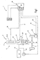
- FIG. 1 shows a schematic diagram of a first embodiment of the device 1 for a vehicle not shown in detail 3, which has a drive assembly 5 with a drive train 7.
- the drive train 7 serves to drive wheels 11 and 13 arranged on an axle 9.
- the drive assembly 5 has an internal combustion engine 15, which is here formed by an internal combustion engine 16, and an electric machine 17, the rotor, not shown, both with the crankshaft 19 of the engine 16 and with an input part 21 of a clutch 23, such as friction clutch rotatably is coupled.
- a clutch 23 such as friction clutch rotatably is coupled.
- electrically or mechanically actuated coupling 23 allows in a first switching position that the crankshaft 19 of the engine 16 and the rotor of the electric machine 17 can rotate without the wheels 11, 13 of this with a torque (drive or braking torque) be charged.
- a torque converter can also be used.
- a transmission 25, such as manual or automatic transmission, and a differential gear 27 are further provided.
- the clutch 23, the transmission 25 and the differential gear 27 are optional devices that are not required for carrying out the method according to the invention.
- the internal combustion engine 16 and the electric machine 17 are preferably always used together in order to accelerate or decelerate the vehicle 3. It is readily possible that only by means of the electric machine 17, a predetermined torque is applied to the wheels 11, 13, for example, when the engine 16 fails or the (hybrid) vehicle 3 is to be driven only by electrical energy. Of course, it is also possible to use only the internal combustion engine 16 for applying the wheels 11, 13 with a torque, while the electric machine 17 is in an inactive state.
- the vehicle 3 further includes a brake 29 to brake the wheels 11, 13.
- the brake 29 may be associated with only one of the wheels of the vehicle 3, as indicated in FIG. 1, or with a plurality of wheels. Structure and function of such a brake 29 is known, so that will not be discussed here in detail.
- the device 1 comprises a control unit 31 with at least one electronic control unit 33, by means of which the torque of the internal combustion engine 16 is controllable, as indicated by a control arrow 35 shown in dashed lines. By varying the torque of the internal combustion engine 16, the speed of the vehicle 3 can be changed.
- the electronic control unit 33 comprises means 37 for detecting the current / current Speed of the vehicle 3 and means 39 for setting a target speed of the vehicle 3.
- the means 37, 39 are known per se, so that they are not described in detail.
- the control unit 31 may also have a plurality of control units, which are in data communication with one another, instead of the individual electronic control unit 33.
- the electric machine 17 can be used in the operation of the vehicle 3 optionally as a generator and as a motor. In generator operation, the electric machine 17 can apply a torque for deceleration (deceleration) of the vehicle 3 and, during engine operation, a torque for acceleration (drive) of the vehicle 3.
- the electric machine 17 further comprises known means for driving, via which a desired torque can be specified. This is preferably done via the electronic control unit 33, which is indicated by a dashed arrow control arrow 41.
- the electric machine 17 is connected via electrical lines 43 and 45 to a power storage 47, for example a battery, and at least one consumer 49, for example a heating or air conditioning system.
- a power storage 47 for example a battery
- at least one consumer 49 for example a heating or air conditioning system.
- motor operation of the electric machine 17 of the power storage 47 provides power to drive the vehicle 3, in the regenerative operation of the same receive power storage 47 and consumer 49, the power generated.
- the electronic control unit 33 requests a torque from the internal combustion engine 16 and / or the electric machine 17.
- Strategies are preferably stored in the electronic control unit 33 for optimizing the torque on the two motors 16, 17 to distribute. If the sum of the torques applied by the internal combustion engine 16 and by the electric machine 17 to the wheels 11, 13 is greater than the driving resistances acting on the vehicle 3, this leads to an acceleration of the vehicle 3. In the other case, ie if the sum of the If the engine 16 and the electric machine 17 torque transmitted to the wheels 11, 13 is smaller than the driving resistance, this leads to a delay of the vehicle 3.
- the electronic control unit 33 wants to reduce the speed of the vehicle 3, because the detected by the means 37 current speed of the vehicle 3 is greater than the predetermined speed via the means 39, can also be provided to actuate the brake 29 by the electronic control unit 33, as indicated by a dashed arrow control arrow 51, and thus to reduce the speed even more than this alone by the engine 16 u nd the electric machine 17 is possible.
- the electronic control unit 33 also the electrical power consumption in at least one of the electrical Consumer 49 increases if the power storage 47 can not absorb the entire electric current generated by the electric machine 17 and the deceleration of the vehicle 3 by the braking torque of the electric machine 17 is not sufficient.
- the control of the electrical load 49 by means of the electronic control unit 33 is indicated by a control arrow 53 shown in dashed lines.
- the invention therefore provides for the control of the drive torque to be carried out largely with the aid of the electric machine and with the use of the internal combustion engine as constant as possible.
- the internal combustion engine provides a basic drive torque which results from the dynamic driving equation. This basic drive torque is set at an operating point of the internal combustion engine at which the fuel consumption and / or the exhaust emissions are as small as possible. Short-term fluctuations the required total drive torque can be compensated exclusively by means of the electric machine.
- the combination with a CVT or automatic transmission and a coordinated powertrain control offers further optimization potential.
- the internal combustion engine can be operated at the lowest possible rotational speeds and in the case of gasoline engines as much as possible without throttling.
- the advantage is that internal combustion engines (internal combustion engines) can usually be operated fuel-efficient and also with low exhaust emissions and also the torque of an electric motor is usually greatest at low speeds and thus also the effect to be achieved.
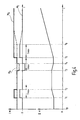
- Graph I shows the torque M E provided by the electric machine, the torque M B provided by the internal combustion engine, and the desired / required total drive torque M G , which is composed of the individual torques, as a function of the altitude profile of the driving route shown in graph II.
- recuperative braking charging of the current memory (battery)
- too low a driving speed is compensated by outputting a positive torque from the electric machine.
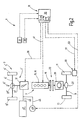
- Figure 2 shows a schematic diagram of a second embodiment of the device 1.
- the same parts are provided with the same reference numerals, so that in this respect reference is made to the description of Figure 1. In the following, therefore, only the differences are discussed in more detail.
- the vehicle 3 has a drive arrangement 5 'which has first and second drive trains 7 and 7', of which the drive train 7 is the wheels 11, 13 of the axle 9 (front or rear axle) and the other drive train 7 'is a wheel 11'.
- a second axis 9 '(rear or front axle) is assigned.
- the first drive train 7 comprises the internal combustion engine 16, the clutch 23, the transmission 25 and the differential gear 27 and serves to drive the wheels 11, 13.
- the second drive train 7 ' comprises the electric machine 17, which via its drive part 21 with the wheel 11th 'the other axis 9' of the vehicle 3 rotatably coupled to apply this with a drive or braking torque.
- Figure 2 is indicated by dashed lines that in a further embodiment, the electric machine 17 by means of a differential gear 27 'in addition, the at least one other wheel 13' on the axis 9 'can drive.
- the electric machine 17 by means of a differential gear 27 'in addition, the at least one other wheel 13' on the axis 9 'can drive.
- at least two electrical machines are provided, each of which is in torque-transmitting connection with one of the wheels 11', 13 '.
- the drive train 7 assigned to the axle 9 has the same structure as the drive train 7 described with reference to FIG. 1, while the at least one further, the axis 9 'or only the wheel 11' associated drive train 7 'as described above is formed.
- the method for regulating the travel speed of the exemplary embodiment described with reference to FIG. 2 essentially corresponds to the method described with reference to FIG. That is, the electronic control unit 33 can demand from the electric machine 17 and the engine 16 independently of each other dependent on the actual and the target speed of the vehicle 3 torque. It is therefore easily possible that the wheel 11 'or the wheels 11' and 13 'of the second axis 9' and the wheels 11 and 13 of the first axis 9 are acted upon with different or different magnitudes of torques, which is advantageous in certain driving situations can be.
- the exemplary embodiment according to FIG. 2 differs from that described with reference to FIG. 1 in particular in that the internal combustion engine 16 and the electric machine 17 can be controlled independently of one another and one other axle or at least one wheel per vehicle axle can be driven independently of the other wheel , It should be noted that the drive arrangement 5 'shown in FIG. 2 enables four-wheel drive.
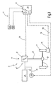
- FIG. 3. shows a schematic circuit diagram of a third embodiment of the device 1. Parts which have already been described with reference to Figures 1 and 2 are provided with the same reference numerals. It Reference is therefore made to the description of Figures 1 and 2.
- the vehicle has a drive arrangement 5 "with only one drive train 7 with at least one electric machine 17, but no internal combustion engine, ie, this is a pure electric vehicle Alternatively, it may be provided to dispense with the differential gear 27 and to directly connect the electric machine 17 only with only one of the wheels 11, 13.
- a plurality of electrical machines are provided each driving a wheel of the vehicle, which wheels may be on different axes.
- neither a clutch 23 nor a transmission 25 is provided in the drive train 7.
- At least one fuel cell preferably a plurality of fuel cells, may be provided as the source of the electrical current instead of at least one battery as the energy store 47.
- the method that can be implemented by means of the embodiment shown in FIG. 3 for regulating the driving speed of the vehicle 3 is analogous to the method described with reference to FIGS. 1 and 2. So if the electronic control unit 33 determines that the detected via the means 37 actual travel speed of the vehicle 3 is smaller than the predetermined speed via the means 39, the electronic control unit 33 from the electric machine 17 requests a positive torque, which leads to the acceleration of the vehicle 3. If the electronic control unit 33 requests a deceleration of the vehicle 3 from the comparison of the actual speed and the set speed, a negative torque is demanded from the electric machine 17 via the data connection 35.
- the controller 33 and the brake 29 is operated for the at least one wheel 11 to delay the vehicle 3 even more, if the negative torque of the electric machine 17 alone is insufficient.
- the electronic control unit 33 at least one electrical load 49 increases the absorption of electrical current, if the current memory 47 can not absorb the entire electrical power generated by the electric machine 17 in generator operation and the delay through the Braking torque of the electric machine 17 is not sufficient.
Landscapes
- Engineering & Computer Science (AREA)
- Chemical & Material Sciences (AREA)
- Combustion & Propulsion (AREA)
- Transportation (AREA)
- Mechanical Engineering (AREA)
- Automation & Control Theory (AREA)
- Electric Propulsion And Braking For Vehicles (AREA)
- Hybrid Electric Vehicles (AREA)
- Control Of Driving Devices And Active Controlling Of Vehicle (AREA)
- Controls For Constant Speed Travelling (AREA)
- Control Of Vehicle Engines Or Engines For Specific Uses (AREA)
Abstract
Description
- Die Erfindung betrifft ein Verfahren zur Regelung der Fahrgeschwindigkeit eines Fahrzeugs gemäß dem Oberbegriff des Anspruchs 1.
- Verfahren zur Regelung der Fahrgeschwindigkeit eines Fahrzeugs sind bekannt. Sie werden auch als ACC-Systeme (Adaptive Cruise Control), Fahrgeschwindigkeitsregler oder Tempomat bezeichnet.
- Es sind Kraftfahrzeuge bekannt, die im Antriebsstrang neben einer Brennkraftmaschine auch noch eine elektrische Maschine aufweisen. Solche elektrische Maschinen im Antriebstrang eines Kraftfahrzeugs werden auch als Starter-Generator, Kurbelwellen-Starter-Generator oder integrierter Starter-Generator bezeichnet.
- Aus der DE 199 14 428 Cl ist eine Antriebsanordnung für ein Kraftfahrzeug bekannt, bei der das Bremsmoment einer elektrischen Maschine im Antriebstrang in Verbindung mit einem automatischen Geschwindigkeits- und Abstandsregelsystem eingesetzt wird. Dabei wird die mit dem Verbrennungsmotor gekoppelte elektrische Maschine im Fahrbetrieb des Kraftfahrzeug stets generatorisch als Lichtmaschine betrieben, um den Verbrennungsmotor zu bremsen und somit den Antriebsstrang mit einem Lastmoment zu beaufschlagen.
- Ein Verfahren gemäß dem Oberbegriff des Anspruchs 1 ist in der US-B1-6 209 672 für ein Hybridfahrzeug mit zwei Elektromotoren beschrieben.
- Weiter offenbart die US-A-6 122 588 ein System und ein Verfahren zur Verringerung einer Geschwindigkeit eines Fahrzeugs, um eine Sollgeschwindigkeit aufrecht zu erhalten, wobei die Sollgeschwindigkeit mit der Istgeschwindigkeit verglichen wird, um eine Geschwindigkeitsabweichung zu bestimmen, und wobei in Abhängigkeit von der Geschwindigkeitsabweichung durch regeneratives Bremsen ein kontinuierlich veränderliches Bremsmoment erzeugt wird, wenn die Istgeschwindigkeit die Sollgeschwindigkeit übersteigt.
- Das erfindungsgemäße Verfahren zeichnet sich dadurch aus, dass bei einer Istgeschwindigkeit größer als die Sollgeschwindigkeit eine Verzögerung des Fahrzeugs gefordert und hierzu die elektrische Maschine als Generator betrieben wird und dass bei einer Istgeschwindigkeit kleiner als die Sollgeschwindigkeit die elektrische Maschine als Motor betrieben wird, dass kurzzeitige und/oder relativ kleine Schwankungen im erforderlichen Antriebsmoment, um das Fahrzeug auf einer konstanten Geschwindigkeit zu halten, ausschließlich durch die elektrische Maschine ausgeglichen werden, und dass nach einer bestimmten Zeitdauer, in der Schwankungen des Antriebsmoments ausschließlich durch die elektrische Maschine ausgeglichen wurden, das Drehmoment der Brennkraftmaschine, vorzugsweise mittels eines Integrators, auf- beziehungsweise abgeregelt und der Anteil der elektrischen Maschine am Gesamtantriebsmoment gegen Null zurückgeführt wird.
- Das von einem Fahrgeschwindigkeitsregler in Abhängigkeit der Ist- und der Sollgeschwindigkeit des Fahrzeugs geforderte Drehmoment, das auf mindestens ein Rad des Fahrzeugs übertragen wird, kann je nach Ausgestaltung der Antriebsanordnung des Fahrzeugs wahlweise von der elektrischen Maschine oder der Brennkraftmaschine oder von der elektrischen Maschine und der Brennkraftmaschine aufgebracht werden. In der Steuereinheit des Fahrgeschwindigkeitsreglers können hierzu Strategien abgelegt sein, um das geforderte Drehmoment optimal auf die elektrische Maschine und die Brennkraftmaschine zu verteilen. Ist die Summe der auf das mindestens eine Rad übertragenen Drehmomente größer als die auf das Fahrzeug wirkenden Fahrwiderstände, führt das zu einer Beschleunigung des Fahrzeugs, während wenn die Summe dieser Drehmomente kleiner als die Fahrwiderstände sind, dies zu einer Verzögerung (Bremsung) des Fahrzeugs führt.
- Dies bietet den Vorteil, dass die mindestens eine im Fahrzeug vorgesehene elektrische Maschine in Verbindung mit der Vorrichtung (Fahrgeschwindigkeitsregler) zur Regelung der Fahrgeschwindigkeit des Fahrzeugs vielfältig einsetzbar ist, also nicht nur zum Abbremsen, sondern auch zum Beschleunigen des Fahrzeugs.
- Zur Reduzierung der Fahrgeschwindigkeit des Fahrzeugs kann weiter vorgesehen sein, dass auch eine mindestens einem Rad des Fahrzeugs zugeordnete Bremseinrichtung betätigt wird. Dadurch kann die Fahrgeschwindigkeit noch stärker reduziert werden, als dies allein durch die Brennkraftmaschine und die elektrische Maschine möglich ist.
- Eine zur Durchführung des erfindungsgemäßen Verfahrens geeignete Vorrichtung kann eine Steuereinheit zur Steuerung des Drehmoments der elektrische Maschine und Mittel zur Ansteuerung der elektrischen Maschine umfassen, über die ein gewünschtes Drehmoment (Antriebs- oder Bremsmoment) vorgegeben werden kann. Darüber hinaus sind Mittel zur Erfassung der Istgeschwindigkeit des Fahrzeugs sowie Mittel zur Vorgabe der Sollgeschwindigkeit des Fahrzeugs vorgesehen. Die Erfassung der Istgeschwindigkeit kann auf unterschiedlichste Weise erfolgen, zum Beispiel mittels eines die Drehzahl eines Rades erfassenden Sensors. Zur Vorgabe der Sollgeschwindigkeit sind ebenfalls mehrere Möglichkeiten denkbar, beispielsweise kann ein Fahrzeuginsasse, insbesondere der Fahrer, über ein Bedienelement eine gewünschte Geschwindigkeit vorgeben. Die Mittel zur Vorgabe der Sollgeschwindigkeit können auch eine Einrichtung zur Einstellung des Abstands des Fahrzeugs zu einem Objekt, insbesondere einem vorausfahrenden Fahrzeug, umfassen (Geschwindigkeits- und Abstandsregelsystem, beispielsweise ACC-System). Eine dritte Ausführungsvariante sieht vor, dass der Steuereinheit über eine Datenverbindung, beispielsweise Satellitenverbindung, eine Sollgeschwindigkeit vorgegeben wird.
- Vorteilhafte Ausführungsvarianten des Verfahrens ergeben sich aus Kombinationen der aus den Unteransprüchen hervorgehenden Merkmale.
- Die Erfindung wird nachfolgend anhand der zugehörigen Zeichnungen noch näher erläutert. Es zeigen:
- Figuren 1 bis 3
- jeweils ein Prinzipschaltbild einer Antriebsanordnung für ein Fahrzeug; und
- Figur 4
- zwei Graphen, bei denen der Gesamtbedarf des Antriebsmoments bei einer konstanten Fahrgeschwindigkeit (Graph I) in Abhängigkeit von dem Höhenprofil der Fahrstrecke (Graph II) dargestellt ist.
- Im Folgenden werden anhand der Figuren mehrere Ausführungsbeispiele einer Vorrichtung 1 zur automatischen Regelung der Fahrgeschwindigkeit eines Fahrzeugs, beispielsweise Personenkraftwagen (Pkw), Lastkraftwagen (Lkw), Omnibus oder dergleichen, näher erläutert.
- Figur 1 zeigt ein Prinzipschaltbild eines ersten Ausführungsbeispiels der Vorrichtung 1 für ein nicht näher dargestelltes Fahrzeug 3, das eine Antriebsanordnung 5 mit einem Antriebsstrang 7 aufweist. Der Antriebsstrang 7 dient zum Antreiben von auf einer Achse 9 angeordneten Rädern 11 und 13.
- Die Antriebsanordnung 5 weist eine Brennkraftmaschine 15, die hier von einem Verbrennungsmotor 16 gebildet ist, und eine elektrische Maschine 17 auf, deren nicht dargestellter Rotor sowohl mit der Kurbelwelle 19 des Verbrennungsmotors 16 als auch mit einem Eingangsteil 21 einer Kupplung 23, beispielsweise Reibungskupplung, drehfest gekoppelt ist. Die beispielsweise elektrisch oder mechanisch betätigbare Kupplung 23 ermöglicht in einer ersten Schaltstellung, dass sich die Kurbelwelle 19 des Verbrennungsmotors 16 und der Rotor der elektrische Maschine 17 drehen können, ohne dass die Räder 11, 13 von dieser mit einem Drehmoment (Antriebs- oder Bremsmoment) beaufschlagt werden.
- Alternativ zur Kupplung 23 kann auch ein Drehmomentwandler eingesetzt werden.
- Im Antriebsstrang 7 sind ferner ein Getriebe 25, beispielsweise Schalt- oder Automatikgetriebe, und ein Differenzialgetriebe 27 vorgesehen. Es bleibt festzuhalten, dass die Kupplung 23, das Getriebe 25 und das Differenzialgetriebe 27 optionale Einrichtungen sind, die zur Durchführung des erfindungsgemäßen Verfahrens nicht erforderlich sind.
- Bei geschlossener Kupplung 23 stehen sowohl der Verbrennungsmotor 16 als auch die elektrische Maschine 17 über den Rotor derselben, der Kupplung 23, dem Getriebe 25 und dem Differenzialgetriebe 27 in drehmomentübertragbarer Verbindung mit den Rädern 11, 13, so dass auf diese ein Antriebs-oder Bremsmoment übertragbar ist. Bei dieser Ausführungsform der Antriebsanordnung 5 werden Verbrennungsmotor 16 und elektrische Maschine 17 vorzugsweise immer gemeinsam eingesetzt, um das Fahrzeug 3 zu beschleunigen beziehungsweise zu verzögern. Es ist ohne weiteres möglich, dass nur mittels der elektrischen Maschine 17 ein vorgebbares Drehmoment auf die Räder 11, 13 aufgebracht wird, beispielsweise dann, wenn der Verbrennungsmotor 16 ausfällt oder das (Hybrid-)Fahrzeug 3 nur mittels elektrischer Energie angetrieben werden soll. Selbstverständlich ist es auch möglich, nur den Verbrennungsmotor 16 zum Beaufschlagen der Räder 11, 13 mit einem Drehmoment einzusetzen, während sich die elektrische Maschine 17 dabei in einem inaktivem Zustand befindet.
- Das Fahrzeug 3 weist ferner eine Bremse 29 auf, um die Räder 11, 13 abzubremsen. Die Bremse 29 kann lediglich einem der Räder des Fahrzeugs 3 zugeordnet sein, .wie in Figur 1 angedeutet, oder mehreren Rädern. Aufbau und Funktion einer derartigen Bremse 29 ist bekannt, so dass hier nicht näher darauf eingegangen wird.
- Die Vorrichtung 1 umfasst eine Steuereinheit 31 mit wenigstens einem elektronischen Steuergerät 33, mittels dessen das Drehmoment des Verbrennungsmotors 16 steuerbar ist, wie mit einem gestrichelt dargestellten Steuerpfeil 35 angedeutet. Durch Variation des Drehmoments des Verbrennungsmotors 16 kann die Geschwindigkeit des Fahrzeugs 3 verändert werden. Das elektronische Steuergerät 33 umfasst Mittel 37 zur Erfassung der aktuellen/momentanen Geschwindigkeit des Fahrzeugs 3 und Mittel 39 zur Vorgabe einer Sollgeschwindigkeit des Fahrzeugs 3. Die Mittel 37, 39 sind an sich bekannt, so dass diese nicht näher beschrieben werden.
- Die Steuereinheit 31 kann anstelle des einzelnen elektronischen Steuergeräts 33 auch mehrere Steuergeräte aufweisen, die in Datenverbindung miteinander stehen.
- Die elektrische Maschine 17 ist im Betrieb des Fahrzeugs 3 wahlweise als Generator und als Motor einsetzbar. Im generatorischen Betrieb kann die elektrische Maschine 17 ein Drehmoment zur Verzögerung (Abbremsung) des Fahrzeugs 3 und im motorischen Betrieb ein Drehmoment zur Beschleunigung (Antrieb) des Fahrzeugs 3 aufbringen. Die elektrische Maschine 17 umfasst ferner an sich bekannte Mittel zur Ansteuerung, über die ein gewünschtes Drehmoment vorgegeben werden kann. Dies erfolgt vorzugsweise über das elektronische Steuergerät 33, was mit einem gestrichelt dargestellten Steuerpfeil 41 angedeutet ist.
- Die elektrische Maschine 17 ist über elektrische Leitungen 43 und 45 mit einem Stromspeicher 47, beispielsweise einer Batterie, und wenigstens einem Verbraucher 49, beispielsweise einer Heizungs- oder Klimaanlage verbunden. Im motorischen Betrieb der elektrische Maschine 17 liefert der Stromspeicher 47 Strom zum Antrieb des Fahrzeugs 3, im generatorischen Betrieb derselben nehmen Stromspeicher 47 und Verbraucher 49 den erzeugten Strom auf.
- Zur Funktion der Vorrichtung 1: Zur Einstellung der über das Mittel 39 vorgegebenen Geschwindigkeit fordert das elektronische Steuergerät 33 ein Drehmoment vom Verbrennungsmotor 16 und/oder der elektrischen Maschine 17. Im elektronischen Steuergerät 33 sind hierzu vorzugsweise Strategien abgelegt, das Drehmoment optimal auf die beiden Motoren 16, 17 zu verteilen. Ist die Summe der vom Verbrennungsmotor 16 und von der elektrische Maschine 17 auf die Räder 11, 13 aufgebrachten Drehmomente größer als die auf das Fahrzeug 3 wirkenden Fahrwiderstände, führt das zu einer Beschleunigung des Fahrzeugs 3. Im anderen Fall, also wenn die Summe der vom Verbrennungsmotor 16 und der elektrische Maschine 17 auf die Räder 11, 13 übertragenen Drehmomente kleiner als die Fahrwiderstände ist, führt dies zu einer Verzögerung des Fahrzeugs 3. Wenn das elektronische Steuergerät 33 die Geschwindigkeit des Fahrzeugs 3 reduzieren will, weil die über die Mittel 37 erfasste aktuelle Geschwindigkeit des Fahrzeugs 3 größer ist als die über die Mittel 39 vorgegebene Sollgeschwindigkeit, kann weiterhin vorgesehen sein, auch die Bremse 29 durch das elektronische Steuergerät 33 zu betätigen, wie mit einem gestrichelt dargestellten Steuerpfeil 51 angedeutet, und so die Geschwindigkeit noch stärker zu reduzieren, als dies allein durch den Verbrennungsmotor 16 und die elektrische Maschine 17 möglich ist.
- Besonders vorteilhaft ist es, wenn in dem Fall, dass das Fahrzeug 3 verzögert werden soll, das elektronische Steuergerät 33 auch die elektrische Leistungsaufnahme bei mindestens einem der elektrischen Verbraucher 49 erhöht, falls der Stromspeicher 47 nicht den gesamten, von der elektrischen Maschine 17 erzeugten elektrischen Strom aufnehmen kann und die Verzögerung des Fahrzeugs 3 durch das Bremsmoment der elektrischen Maschine 17 nicht ausreichend ist. Die Ansteuerung des elektrischen Verbrauchers 49 mittels des elektronischen Steuergeräts 33 ist mit einem gestrichelt dargestellten Steuerpfeil 53 angedeutet.
- Im Folgenden wird eine besonders vorteilhafte Ausführungsvariante zur Regelung der Fahrgeschwindigkeit beschrieben, die bei einem Fahrzeug mit einer Antriebsanordnung, die wenigstens eine elektrische Maschine und mindestens eine Brennkraftmaschine aufweist, also wie sie zum Beispiel anhand der Figur 1 beschrieben wurde, einsetzbar ist.
- Bei Aktivierung des vorstehend beschriebenen Fahrgeschwindigkeitsregler versucht dieser, die Geschwindigkeit des Fahrzeugs konstant beziehungsweise im Wesentlichen konstant zu halten, was bei Fahrten in hügligem Gelände zu erheblichen Änderungen des benötigten Antriebsmoments führt. Erfindungsgemäß ist daher vorgesehen, die Regelung des Antriebsmoments weitgehend mit Hilfe der elektrischen Maschine und mit möglichst konstanter Einsatz der Brennkraftmaschine durchzuführen. Die Brennkraftmaschine stellt dabei ein Grundantriebsmoment bereit, das sich aus der fahrdynamischen Gleichung ergibt. Dieses Grundantriebsmoment wird an einem Arbeitspunkt der Brennkraftmaschine eingestellt, an dem der Kraftstoffverbrauch und/oder die Abgasemissionen möglichst klein sind. Kurzzeitige Schwankungen des erforderlichen Gesamtantriebsmoments werden ausschließlich mittels der elektrischen Maschine ausgeglichen. Die Verbindung mit einem CVT- oder Automatikgetriebe und einer koordinierten Antriebsstrangsteuerung bietet weiteres Optimierungspotential. Dadurch kann die Brennkraftmaschine bei möglichst niedrigen Drehzahlen und im Falle von Benzinmotoren möglichst ungedrosselt betrieben werden. Der Vorteil besteht darin, dass Brennkraftmaschinen (Verbrennungsmotoren) hier in der Regel verbrauchsgünstig und auch mit geringen Abgasemissionen betrieben werden können und auch das Drehmoment eines Elektromotors in der Regel bei niedrigen Drehzahlen am größten ist und damit auch der zu erzielende Effekt.
- Das vorstehend beschriebene Verfahren wird im Folgenden anhand der Figur 4 näher erläutert. Der Graph I zeigt das von der elektrischen Maschine bereitgestellte Drehmoment ME, das von der Brennkraftmaschine bereitgestellte Drehmoment MB sowie das gewünschte/erforderliche, sich aus den Einzeldrehmomenten zusammensetzende Gesamtantriebsmoment MG in Abhängigkeit von dem im Graph II dargestellten Höhenprofil der Fahrstrecke. Um die Fahrgeschwindigkeit konstant zu halten, wird eine zu hohe resultierende Geschwindigkeit durch rekuperatives Bremsen (Laden des Stromspeichers (Batterie)) ausgeglichen, während eine zu geringe Fahrgeschwindigkeit durch Abgabe eines positiven Drehmoments von der elektrischen Maschine kompensiert wird. Erst bei längeren Be- beziehungsweise Entladephasen des Stromspeichers (t > Tmax) wird das Drehmoment der Brennkraftmaschine über einen Integrator auf- beziehungsweise abgeregelt und der Anteil der elektrischen Maschine am Gesamtantriebsmoment entsprechend in Richtung Null zurück geführt. Das heißt, in der Zeit von t0 bis t6 ist das Drehmoment der Brennkraftmaschine konstant und steigt erst nach dem Zeitpunkt t6 an, da zu diesem Zeitpunkt die Entladephase der Batterie größer als Tmax ist und das Drehmoment der elektrischen Maschine gegen Null zurück geführt wird. Sollte das zusätzliche Drehmoment der elektrischen Maschine nicht ausreichen, um die gewünschte Zielgeschwindigkeit (Sollgeschwindigkeit) des Fahrzeugs beizubehalten, wird entweder das Drehmoment der Brennkraftmaschine oder die Getriebeübersetzung angepasst.
- Aus Figur 4 wird ohne weiteres deutlich, dass bei aktivem Fahrgeschwindigkeitsregler das Gesamtdrehmoment, um das Fahrzeug konstant auf einer gewünschten Geschwindigkeit zu halten, konsequent zwischen der elektrischen Maschine und der Brennkraftmaschine aufgeteilt wird. Bei ebenen Fahrstrecken und auf Fahrstrecken mit konstanter Steigung gelingt das Ausregeln der gewünschten Geschwindigkeit mit hoher Genauigkeit und geringer Aktivität des Fahrgeschwindigkeitsreglers. Erst durch das Aufteilen des Gesamtantriebsmoments und einen möglichst weitgehenden Verzicht auf Änderungen des Arbeitspunktes der Brennkraftmaschine kann auch bei langen Fahrstrecken mit konstanter Geschwindigkeit der Kraftstoffverbrauch gering gehalten werden.
- Figur 2 zeigt ein Prinzipschaltbild eines zweiten Ausführungsbeispiels der Vorrichtung 1. Gleiche Teile sind mit gleichen Bezugszeichen versehen, so dass insofern auf die Beschreibung zur Figur 1 verwiesen wird. Im Folgenden wird daher nur auf die Unterschiede näher eingegangen.
- Das Fahrzeug 3 weist eine Antriebsanordnung 5' auf, die erste und zweite Antriebsstränge 7 und 7' aufweist, von denen der Antriebsstrang 7 den Rädern 11, 13 der Achse 9 (Vorder- oder Hinterachse) und der andere Antriebsstrang 7' einem Rad 11' einer zweiten Achse 9' (Hinter- oder Vorderachse) zugeordnet ist. Der erste Antriebsstrang 7 umfasst den Verbrennungsmotor 16, die Kupplung 23, das Getriebe 25 sowie das Differenzialgetriebe 27 und dient zum Antrieb der Räder 11, 13. Der zweite Antriebsstrang 7' umfasst die elektrische Maschine 17, die über ihr Antriebsteil 21 mit dem Rad 11' der anderen Achse 9' des Fahrzeugs 3 drehfest gekoppelt, um dieses mit einem Antriebs- oder Bremsmoment zu beaufschlagen.
- In Figur 2 ist mit gestrichelten Linien angedeutet, dass bei einer weiteren Ausführungsvariante die elektrische Maschine 17 mittels eines Differenzialgetriebes 27' zusätzlich auch das mindestens eine andere Rad 13' an der Achse 9' antreiben kann. Bei einer dritten, nicht dargestellten Ausführungsvariante des zweiten Antriebsstrangs 7' sind mindestens zwei elektrische Maschinen vorgesehen, die jeweils mit einem der Räder 11', 13' in drehmomentübrtragender Verbindung stehen. Bei einer ebenfalls nicht dargestellten vierten Ausführungsvariante ist der der Achse 9 zugeordnete Antriebsstrang 7 identisch aufgebaut wie der anhand der Figur 1 beschriebene Antriebsstrang 7, während der mindestens eine weitere, der Achse 9' beziehungsweise lediglich dem Rad 11' zugeordnete Antriebsstrang 7' wie vorstehend beschrieben ausgebildet ist.
- Das Verfahren zur Regelung der Fahrgeschwindigkeit des anhand der Figur 2 beschriebenen Ausführungsbeispiels entspricht im Wesentlichen dem anhand der Figur 1 beschriebenen Verfahren. Das heißt, das elektronische Steuergerät 33 kann von der elektrische Maschine 17 und dem Verbrennungsmotor 16 unabhängig voneinander ein von der Ist-und der Sollgeschwindigkeit des Fahrzeugs 3 abhängiges Drehmoment fordern. Es ist daher ohne weiteres möglich, dass das Rad 11' beziehungsweise die Räder 11' und 13' der zweiten Achse 9' sowie die Räder 11 und 13 der ersten Achse 9 mit unterschiedlichen beziehungsweise mit unterschiedlich großen Drehmomenten beaufschlagt werden, was in bestimmten Fahrsituationen vorteilhaft sein kann.
- Das Ausführungsbeispiel gemäß Figur 2 unterscheidet sich von dem anhand der Figur 1 beschriebenen also insbesondere dadurch, dass der Verbrennungsmotor 16 und die elektrische Maschine 17 unabhängig voneinander ansteuerbar sind und jeweils eine andere Achse beziehungsweise mindestens ein Rad pro Fahrzeugachse unabhängig vom jeweils anderen Rad angetrieben werden kann. Festzuhalten bleibt, dass die in Figur 2 dargestellte Antriebsanordnung 5' einen Allradantrieb ermöglicht.
- Figur. 3. zeigt ein Prinzipschaltbild eines dritten Ausführungsbeispiels der Vorrichtung 1. Teile, die bereits anhand der Figuren 1 und 2 beschrieben wurden, sind mit gleichen Bezugszeichen versehen. Es wird daher auf die Beschreibung der Figuren 1 und 2 verwiesen. Das Fahrzeug weist eine Antriebsanordnung 5" mit nur lediglich einem Antriebsstrang 7 mit mindestens einer elektrischen Maschine 17 auf, jedoch keine Brennkraftmaschine. Es handelt sich hier also um ein reines Elektrofahrzeug. Die elektrische Maschine 17 ist hier direkt über das Antriebsteil 21 und das Differenzialgetriebe 27 mit beiden Rädern 11, 13 der Achse 9 drehfest verbunden. Alternativ kann vorgesehen sein, auf das Differenzialgetriebe 27 zu verzichten und die elektrische Maschine 17 lediglich nur mit einem der Räder 11, 13 direkt zu verbinden. Bei einer weiteren Ausführungsvariante sind mehrere elektrische Maschinen vorgesehen, die jeweils ein Rad des Fahrzeugs antreiben, wobei diese Räder sich auf unterschiedlichen Achsen befinden können.
- Bei dem in Figur 3 dargestellten Ausführungsbeispiel ist im Antriebsstrang 7 weder eine Kupplung 23 noch ein Getriebe 25 vorgesehen. Es ist jedoch ohne weiteres möglich, diese Einrichtungen im Antriebsstrang 7 vorzusehen.
- Bei der in Figur 3 dargestellten Antriebsanordnung 5" kann anstelle mindestens einer Batterie als Stromspeicher 47 auch wenigstens eine Brennstoffzelle, vorzugsweise mehrere Brennstoffzellen, als Quelle des elektrischen Stroms vorgesehen sein.
- Das sich mittels dem in Figur 3 dargestellten Ausführungsbeispiel realisierbare Verfahren zur Regelung der Fahrgeschwindigkeit des Fahrzeugs 3 ist analog zu den anhand der Figuren 1 und 2 beschrieben Verfahren. Wenn also das elektronische Steuergerät 33 feststellt, dass die über die Mittel 37 erfasste aktuelle Fahrgeschwindigkeit des Fahrzeugs 3 kleiner als die über die Mittel 39 vorgegebene Sollgeschwindigkeit ist, fordert das elektronische Steuergerät 33 von der elektrischen Maschine 17 ein positives Drehmoment, das zur Beschleunigung des Fahrzeugs 3 führt. Fordert das elektronische Steuergerät 33 aus dem Vergleich von Ist- und Sollgeschwindigkeit eine Verzögerung des Fahrzeugs 3, so wird über die Datenverbindung 35 ein negatives Drehmoment von der elektrischen Maschine 17 gefordert. Auch hier ist es vorteilhaft, wenn das Steuergerät 33 auch die Bremse 29 für das mindestens eine Rad 11 betätigt, um das Fahrzeug 3 noch stärker zu verzögern, falls das negative Drehmoment der elektrischen Maschine 17 allein nicht ausreicht. Schließlich ist es auch hier möglich, dass das elektronische Steuergerät 33 bei mindestens einem elektrischen Verbraucher 49 die Aufnahme von elektrischem Strom erhöht, falls der Stromspeicher 47 nicht den gesamten von der elektrischen Maschine 17 im generatorischen Betrieb erzeugten elektrischen Strom aufnehmen kann und die Verzögerung durch das Bremsmoment der elektrischen Maschine 17 nicht ausreichend ist.
Claims (6)
- Verfahren zur Regelung der Fahrgeschwindigkeit eines mindestens eine elektrische Maschine (17) aufweisenden Fahrzeugs (3) in Abhängigkeit von zumindest dessen Istgeschwindigkeit und einer geforderten Sollgeschwindigkeit, wobei die Istgeschwindigkeit ermittelt wird und die Sollgeschwindigkeit einstellbar ist, wobei ein Vergleich der Ist- und der Sollgeschwindigkeit vorgenommen wird, wobei bei einer Istgeschwindigkeit größer als die Sollgeschwindigkeit eine Verzögerung des Fahrzeugs (3) gefordert und hierzu die elektrische Maschine (17) als Generator betrieben wird, und wobei bei einer Istgeschwindigkei kleiner als die Sollgeschwindigkeit die elektrische Maschine (17) als Motor betrieben wird, dadurch gekennzeichnet, dass kurzzeitige und/oder relativ kleine Schwankungen im erforderlichen Antriebsmoment, um das Fahrzeug (3) auf einer konstanten Geschwindigkeit zu halten, ausschließlich durch die elektrische Maschine (17) ausgeglichen werden, und dass nach einer bestimmten Zeitdauer (tmax), in der Schwankungen des Abtriebsmoments ausschließlich durch die elektrische Maschine (17) ausgeglichen wurden, das Drehmoment der Brennkraftmaschine (15), vorzugsweise mittels eines Integrators, auf- beziehungsweise abgeregelt und der Anteil der elektrischen Maschine (17) am Gesamtantriebsmoment gegen Null zurückgeführt wird.
- Verfahren nach Anspruch 1, dadurch gekennzeichnet, dass bei einer Istgeschwindigkeit größer als die Sollgeschwindigkeit zusätzlich mindestens eine, mit wenigstens einem Rad (11; 13; 11'; 13') des Fahrzeugs (3) zusammenwirkende Bremse (29) betätigt wird, um das Bremsmoment zu erhöhen.
- Verfahren nach Anspruch 1 oder 2, dadurch gekennzeichnet, dass zum Zwecke des Verzögerns und des Beschleunigens des Fahrzeugs (3) das Drehmoment einer Brennkraftmaschine (15) des Fahrzeugs (3) entsprechend variiert wird.
- Verfahren nach einem der vorhergehenden Ansprüche , dadurch gekennzeichnet, dass im motorischen Betrieb der elektrischen Maschine (17) diese von mindestens einem Stromspeicher (47) mit Strom zum Antrieb des Fahrzeugs (3) versorgt wird, und dass im generatorischen Betrieb der elektrischen Maschine (17) der erzeugte Strom von dem mindestens einen Stromspeicher (47) und/oder wenigstens einem elektrischen Verbraucher (49) aufgenommen wird.
- Verfahren nach einem, der vorhergehenden Ansprüche, dadurch gekennzeichnet, dass eine zu hohe Fahrgeschwindigkeit des Fahrzeugs (3) durch rekuperatives Bremsen und eine zu geringe Fahrgeschwindigkeit durch Abgabe eines Antriebsmoments von der elektrischen Maschine (17) kompensiert wird.
- Verfahren nach einem der vorhergehenden Ansprüchen, dadurch gekennzeichnet, dass sofern das von der elektrischen Maschine (17) bereitgestellte Drehmoment nicht ausreichend ist, um die geforderte Sollgeschwindigkeit beizubehalten, das Drehmoment der Brennkraftmaschine (15) oder die Getriebeübersetzung entsprechend angepasst wird.
Applications Claiming Priority (3)
| Application Number | Priority Date | Filing Date | Title |
|---|---|---|---|
| DE10162017A DE10162017A1 (de) | 2001-12-18 | 2001-12-18 | Vorrichtung und Verfahren zur Regelung der Fahrgeschwindigkeit eines Fahrzeugs |
| DE10162017 | 2001-12-18 | ||
| PCT/DE2002/004516 WO2003051663A1 (de) | 2001-12-18 | 2002-12-10 | Vorrichtung und verfahren zur regelung der fahrgeschwindigkeit eines fahrzeugs |
Publications (2)
| Publication Number | Publication Date |
|---|---|
| EP1458586A1 EP1458586A1 (de) | 2004-09-22 |
| EP1458586B1 true EP1458586B1 (de) | 2006-06-21 |
Family
ID=7709568
Family Applications (1)
| Application Number | Title | Priority Date | Filing Date |
|---|---|---|---|
| EP02794983A Expired - Lifetime EP1458586B1 (de) | 2001-12-18 | 2002-12-10 | Vorrichtung und verfahren zur regelung der fahrgeschwindigkeit eines fahrzeugs |
Country Status (5)
| Country | Link |
|---|---|
| US (2) | US20040129470A1 (de) |
| EP (1) | EP1458586B1 (de) |
| JP (1) | JP2005512498A (de) |
| DE (2) | DE10162017A1 (de) |
| WO (1) | WO2003051663A1 (de) |
Cited By (1)
| Publication number | Priority date | Publication date | Assignee | Title |
|---|---|---|---|---|
| DE102008051001A1 (de) * | 2008-10-13 | 2010-04-15 | Volkswagen Ag | Abstandssteuerungsvorrichtung und Verfahren zur Steuerung eines Hybridfahrzeuges |
Families Citing this family (35)
| Publication number | Priority date | Publication date | Assignee | Title |
|---|---|---|---|---|
| DE10352799A1 (de) | 2003-11-12 | 2005-06-23 | Robert Bosch Gmbh | Geschwindigkeitsregler für Kraftfahrzeuge |
| US7894971B2 (en) | 2005-12-28 | 2011-02-22 | Toyota Jidosha Kabushiki Kaisha | Vehicle control apparatus |
| DE102006017176A1 (de) * | 2006-04-12 | 2007-10-18 | Robert Bosch Gmbh | Geschwindigkeitsregelvorrichtung und Kraftfahrzeug mit einer solchen Geschwindigkeitsregelvorrichtung |
| JP4554551B2 (ja) | 2006-04-28 | 2010-09-29 | 本田技研工業株式会社 | 車両用走行制御装置 |
| JP4314250B2 (ja) * | 2006-05-23 | 2009-08-12 | トヨタ自動車株式会社 | 車両用の路面判定装置 |
| JP4713408B2 (ja) * | 2006-06-07 | 2011-06-29 | トヨタ自動車株式会社 | 車両の制御装置 |
| US7867122B2 (en) * | 2006-09-26 | 2011-01-11 | Epi-Energy Ltd. | Power transmission system with continuously variable speed control |
| US8430792B2 (en) * | 2006-11-08 | 2013-04-30 | GM Global Technology Operations LLC | Downhill vehicle speed control algorithm for electric driven vehicles |
| US7841433B2 (en) * | 2007-06-20 | 2010-11-30 | Ford Global Technologies, Llc | Negative driveline torque control incorporating transmission state selection for a hybrid vehicle |
| US7828693B2 (en) * | 2007-06-20 | 2010-11-09 | Ford Global Technologies, Llc | Negative driveline torque control incorporating transmission state selection for a hybrid vehicle |
| DE102007029809A1 (de) | 2007-06-27 | 2009-01-08 | Dr. Ing. H.C. F. Porsche Aktiengesellschaft | Verfahren zur Steuerung eines Antriebsstrangs für ein Hybridfahrzeug |
| US7703563B2 (en) | 2007-07-02 | 2010-04-27 | Gm Global Technology Operations, Inc. | Control of hybrid power regeneration during cruise control |
| JP4854609B2 (ja) * | 2007-07-04 | 2012-01-18 | トヨタ自動車株式会社 | 車両の制御装置 |
| DE102007035722A1 (de) | 2007-07-30 | 2009-02-05 | Robert Bosch Gmbh | Verfahren und Vorrichtung zur Vorgabe einer Ausgangsgröße einer Antriebseinheit |
| US7908067B2 (en) | 2007-12-05 | 2011-03-15 | Ford Global Technologies, Llc | Hybrid electric vehicle braking downshift control |
| US8596390B2 (en) * | 2007-12-05 | 2013-12-03 | Ford Global Technologies, Llc | Torque control for hybrid electric vehicle speed control operation |
| US8334679B2 (en) * | 2008-01-22 | 2012-12-18 | Honda Motor Co., Ltd. | ACG output voltage control |
| US8217631B2 (en) | 2008-01-22 | 2012-07-10 | Honda Motor Co., Ltd. | ACG output voltage control |
| JP5491721B2 (ja) * | 2008-11-12 | 2014-05-14 | 本田技研工業株式会社 | 電動パワーステアリング装置の制御装置 |
| JP2011110943A (ja) * | 2009-11-24 | 2011-06-09 | Denso Corp | 車両駆動システムの制御装置 |
| ES2718256T3 (es) * | 2010-12-06 | 2019-06-28 | Iveco Spa | Método para accionar la función de control de crucero en un vehículo equipado con conducción híbrida, especialmente un vehículo comercial o industrial |
| EP2699438A2 (de) * | 2011-04-20 | 2014-02-26 | JOHNSON, Kale R. | Steuerverfahren und system für einen hybridkehrer-schrubber |
| KR101305779B1 (ko) * | 2011-07-21 | 2013-09-17 | 현대자동차주식회사 | 차량용 주행토크제어시스템 및 이의 제어방법 |
| CN103748379B (zh) * | 2011-08-24 | 2016-06-22 | 丰田自动车株式会社 | 车辆用行驶控制装置 |
| DE102011084929A1 (de) * | 2011-10-21 | 2013-04-25 | Zf Friedrichshafen Ag | Verfahren zum Betreiben eines Antriebsstrangs eines Hybridfahrzeugs |
| EP2774802B1 (de) | 2011-11-04 | 2018-04-25 | Toyota Jidosha Kabushiki Kaisha | Fahrzeug und fahrzeugsteuerungsverfahren |
| US9096211B2 (en) | 2012-03-14 | 2015-08-04 | Caterpillar Inc. | Control system having powertrain lock |
| FR2994546B1 (fr) * | 2012-08-16 | 2015-09-04 | Peugeot Citroen Automobiles Sa | Procede de limitation de couple d'une machine electrique de vehicule hybride comportant un systeme de controle de vitesse |
| KR101511678B1 (ko) | 2012-09-17 | 2015-04-17 | 한국에너지기술연구원 | 차량용 연료전지 시스템의 운전비용 관리 방법 |
| GB2508668A (en) * | 2012-12-10 | 2014-06-11 | Jaguar Land Rover Ltd | Adaptive cruise control (ACC) means for a host vehicle having regenerative and non-regenerative braking means |
| GB2508670A (en) * | 2012-12-10 | 2014-06-11 | Jaguar Land Rover Ltd | Hybrid vehicle and boost control for gradients |
| DE102014209395A1 (de) * | 2014-05-19 | 2015-11-19 | Robert Bosch Gmbh | Verfahren zur Verminderung von Schleppmomentschwankungen beim elektrischen Anfahren |
| FR3088880A1 (fr) * | 2018-11-28 | 2020-05-29 | Psa Automobiles Sa | Procédé et dispositif de contrôle de décélération à phase mixte, pour un véhicule à conduite automatisée et machine motrice non-thermique |
| DE102018133649B4 (de) | 2018-12-28 | 2025-05-08 | Volkswagen Aktiengesellschaft | Verfahren zum Betreiben eines Antriebsstrangs eines Kraftfahrzeugs, insbesondere eines Kraftwagens |
| CN112297875B (zh) * | 2020-10-27 | 2022-04-15 | 中车青岛四方机车车辆股份有限公司 | 用于轨道交通车辆恒速运行的控制方法、控制系统及车辆 |
Citations (1)
| Publication number | Priority date | Publication date | Assignee | Title |
|---|---|---|---|---|
| US6122588A (en) * | 1999-10-19 | 2000-09-19 | Ford Global Technologies, Inc. | Vehicle speed control with continuously variable braking torque |
Family Cites Families (33)
| Publication number | Priority date | Publication date | Assignee | Title |
|---|---|---|---|---|
| US4093900A (en) * | 1976-08-11 | 1978-06-06 | General Electric Company | Dynamic brake blending for an inverter propulsion system |
| US5081365A (en) * | 1990-06-06 | 1992-01-14 | Field Bruce F | Electric hybrid vehicle and method of controlling it |
| JPH06255389A (ja) * | 1991-02-26 | 1994-09-13 | Mitsubishi Electric Corp | 車両の走行制御装置 |
| JPH0549106A (ja) | 1991-08-09 | 1993-02-26 | Nissan Motor Co Ltd | モータ制御装置 |
| JPH05111109A (ja) * | 1991-10-08 | 1993-04-30 | Mitsubishi Heavy Ind Ltd | 内燃機関駆動電気式車両の制御方法 |
| US5301764A (en) * | 1992-04-13 | 1994-04-12 | Gardner Conrad O | Hybrid motor vehicle having an electric motor and utilizing an internal combustion engine for fast charge during cruise mode off condition |
| JPH06319205A (ja) | 1993-04-30 | 1994-11-15 | Aqueous Res:Kk | ハイブリッド車両 |
| US5823280A (en) * | 1995-01-12 | 1998-10-20 | Nevcor, Inc. | Hybrid parallel electric vehicle |
| US5544056A (en) * | 1995-01-23 | 1996-08-06 | Seireg; Ali A. | Computerized control of automobile speed |
| JP3011045B2 (ja) | 1995-03-15 | 2000-02-21 | トヨタ自動車株式会社 | 電気自動車 |
| JP3534271B2 (ja) * | 1995-04-20 | 2004-06-07 | 株式会社エクォス・リサーチ | ハイブリッド車両 |
| JP3612828B2 (ja) | 1995-11-30 | 2005-01-19 | 株式会社エクォス・リサーチ | ハイブリッド車両 |
| FR2742100B1 (fr) * | 1995-12-08 | 1998-01-09 | Renault | Vehicule automobile a motorisation hybride |
| JP3255012B2 (ja) * | 1996-05-02 | 2002-02-12 | トヨタ自動車株式会社 | ハイブリッド車 |
| DE19655301B4 (de) | 1996-05-10 | 2006-12-28 | Zf Sachs Ag | Antriebsanordnung für ein Kraftfahrzeug |
| US5710699A (en) * | 1996-05-28 | 1998-01-20 | General Electric Company | Power electronic interface circuits for batteries and ultracapacitors in electric vehicles and battery storage systems |
| JPH1023603A (ja) | 1996-07-05 | 1998-01-23 | Toyota Motor Corp | ハイブリッド車両の制御装置 |
| JP3447937B2 (ja) * | 1997-11-18 | 2003-09-16 | 本田技研工業株式会社 | ハイブリッド車両 |
| GB9818960D0 (en) * | 1998-09-02 | 1998-10-21 | Rover Group | A vehicle |
| US6209672B1 (en) * | 1998-09-14 | 2001-04-03 | Paice Corporation | Hybrid vehicle |
| JP3893778B2 (ja) * | 1998-11-09 | 2007-03-14 | トヨタ自動車株式会社 | ロックアップクラッチ制御装置 |
| JP3546735B2 (ja) * | 1999-01-18 | 2004-07-28 | 日産自動車株式会社 | エンジンの始動制御装置 |
| WO2000046062A1 (fr) * | 1999-02-08 | 2000-08-10 | Toyota Jidosha Kabushiki Kaisha | Vehicule freine par couple moteur et procede de commande du vehicule |
| DE19914428C1 (de) * | 1999-03-30 | 2000-11-30 | Mannesmann Sachs Ag | Antriebsanordnung für ein Kraftfahrzeug |
| DE60023535T2 (de) * | 1999-08-05 | 2006-05-24 | Honda Giken Kogyo K.K. | Regelvorrichtung für ein hybridfahrzeug |
| DE19937381A1 (de) * | 1999-08-07 | 2001-03-22 | Daimler Chrysler Ag | Kraftfahrzeug mit Hybridantrieb und Verfahren zum Betrieb eines Kraftfahrzeugs mit Hybridantrieb |
| DE19955313C2 (de) | 1999-11-17 | 2003-12-18 | Jungheinrich Ag | Antriebssystem für Flurförderzeuge |
| JP3563314B2 (ja) | 1999-11-25 | 2004-09-08 | 本田技研工業株式会社 | ハイブリッド車両のオートクルーズ制御装置 |
| JP3991538B2 (ja) | 1999-12-02 | 2007-10-17 | トヨタ自動車株式会社 | 車両の制御装置 |
| JP4240713B2 (ja) | 2000-01-07 | 2009-03-18 | トヨタ自動車株式会社 | 車両の制御装置 |
| US6484833B1 (en) * | 2000-03-17 | 2002-11-26 | General Motors Corporation | Apparatus and method for maintaining state of charge in vehicle operations |
| US6278916B1 (en) * | 2000-05-09 | 2001-08-21 | Ford Global Technologies, Inc. | Torque control strategy for management of creep and grade hold torque in a wheeled vehicle whose powertrain includes a rotary electric machine |
| JP3454226B2 (ja) * | 2000-05-11 | 2003-10-06 | トヨタ自動車株式会社 | ハイブリッド車両の制御装置 |
-
2001
- 2001-12-18 DE DE10162017A patent/DE10162017A1/de not_active Ceased
-
2002
- 2002-12-10 DE DE50207340T patent/DE50207340D1/de not_active Expired - Lifetime
- 2002-12-10 JP JP2003552565A patent/JP2005512498A/ja active Pending
- 2002-12-10 WO PCT/DE2002/004516 patent/WO2003051663A1/de not_active Ceased
- 2002-12-10 US US10/468,540 patent/US20040129470A1/en not_active Abandoned
- 2002-12-10 EP EP02794983A patent/EP1458586B1/de not_active Expired - Lifetime
-
2007
- 2007-01-16 US US11/654,062 patent/US7416037B2/en not_active Expired - Lifetime
Patent Citations (1)
| Publication number | Priority date | Publication date | Assignee | Title |
|---|---|---|---|---|
| US6122588A (en) * | 1999-10-19 | 2000-09-19 | Ford Global Technologies, Inc. | Vehicle speed control with continuously variable braking torque |
Cited By (1)
| Publication number | Priority date | Publication date | Assignee | Title |
|---|---|---|---|---|
| DE102008051001A1 (de) * | 2008-10-13 | 2010-04-15 | Volkswagen Ag | Abstandssteuerungsvorrichtung und Verfahren zur Steuerung eines Hybridfahrzeuges |
Also Published As
| Publication number | Publication date |
|---|---|
| US20070114084A1 (en) | 2007-05-24 |
| DE10162017A1 (de) | 2003-07-10 |
| US7416037B2 (en) | 2008-08-26 |
| DE50207340D1 (de) | 2006-08-03 |
| JP2005512498A (ja) | 2005-04-28 |
| WO2003051663A1 (de) | 2003-06-26 |
| EP1458586A1 (de) | 2004-09-22 |
| US20040129470A1 (en) | 2004-07-08 |
Similar Documents
| Publication | Publication Date | Title |
|---|---|---|
| EP1458586B1 (de) | Vorrichtung und verfahren zur regelung der fahrgeschwindigkeit eines fahrzeugs | |
| DE69419847T2 (de) | ANTRIEBSSTRANG MIT VORRICHTUNG ZUR ERFASSUNG UND KORREKTUR DES ReCKROLLZUSTANDES EINES ELEKTRISCHEN FAHRZEUGS | |
| DE102005021800B4 (de) | Verfahren zum Steuern eines Motorbremsbetriebs für ein Hybridfahrzeug | |
| DE102017215769B4 (de) | Tempomat-Steuerverfahren für ein Hybridelektrofahrzeug | |
| DE102010015423A1 (de) | Antriebsvorrichtung für ein allradgetriebenes Fahrzeug | |
| EP0830968A1 (de) | Verfahren zum Betrieb eines nichtspurgebundenen Hybridfahrzeuges | |
| DE102008041897A1 (de) | Verfahren zum Betreiben eines Antriebs eines Kraftfahrzeugs sowie Antriebsvorrichtung und elektronisches Steuergerät | |
| WO2002026520A1 (de) | Antriebsstrangsteuerung für ein kraftfahrzeug mit mindestens zwei antriebsaggregaten und einem getriebe | |
| DE10311363A1 (de) | Energieausgabegerät und bewegbarer Körper, an dem das Energieausgabegerät montiert ist | |
| DE102008042228A1 (de) | Verfahren zur Einstellung einer motorischen Antriebseinrichtung in einem Kraftfahrzeug | |
| DE10301531A1 (de) | Einrichtung und Verfahren zum Betrieb einer elektrischen Maschine eines Kraftfahrzeuges | |
| EP3592588B1 (de) | Verfahren zur steuerung eines kraftfahrzeuges und kraftfahrzeug | |
| EP1467886B1 (de) | Verfahren zur steuerung eines hybridantriebes eines fahrzeuges | |
| DE102017103659A1 (de) | Hybridfahrzeug mit Ruckdämpfungsstrategie | |
| EP0798153A1 (de) | Verfahren zum Betreiben einer Antriebseinheit für Fahrzeuge und Antriebseinheit | |
| WO2014029548A1 (de) | Steuervorrichtung für ein generatorisches bremssystem eines fahrzeugs und verfahren zum betreiben eines generatorischen bremssystems eines fahrzeugs | |
| WO2004106102A1 (de) | Kraftfahrzeug-antriebsvorrichtung | |
| DE19914428C1 (de) | Antriebsanordnung für ein Kraftfahrzeug | |
| DE10160018A1 (de) | Verfahren zur Einstellung eines Soll-Betriebszustandes eines Hybridantriebes eines Fahrzeuges | |
| DE102010062379A1 (de) | Verfahren und Vorrichtung zum Antrieb eines Kraftfahrzeuges | |
| DE4292208C2 (de) | Anordnung zum Steuern der Differentialsperre in einem Kraftfahrzeug | |
| DE102020210126A1 (de) | Vorrichtung und verfahren zum steuern eines antreibens eines fahrzeugs mit elektrischem vierradantrieb | |
| WO2004106104A1 (de) | Kraftfahrzeug und elektronische steuereinrichtung dafür | |
| EP1531074B1 (de) | Hybridfahrzeug mit Geschwindigkeitsregler | |
| DE102016214747A1 (de) | Zentraler Längsdynamik-Momentkoordinator und Kraftfahrzeugsteuerung |
Legal Events
| Date | Code | Title | Description |
|---|---|---|---|
| PUAI | Public reference made under article 153(3) epc to a published international application that has entered the european phase |
Free format text: ORIGINAL CODE: 0009012 |
|
| 17P | Request for examination filed |
Effective date: 20040719 |
|
| AK | Designated contracting states |
Kind code of ref document: A1 Designated state(s): AT BE BG CH CY CZ DE DK EE ES FI FR GB GR IE IT LI LU MC NL PT SE SI SK TR |
|
| 17Q | First examination report despatched |
Effective date: 20050610 |
|
| GRAP | Despatch of communication of intention to grant a patent |
Free format text: ORIGINAL CODE: EPIDOSNIGR1 |
|
| RIC1 | Information provided on ipc code assigned before grant |
Ipc: B60K 6/04 20060101ALI20051219BHEP Ipc: B60K 31/04 20060101AFI20051219BHEP |
|
| GRAS | Grant fee paid |
Free format text: ORIGINAL CODE: EPIDOSNIGR3 |
|
| GRAA | (expected) grant |
Free format text: ORIGINAL CODE: 0009210 |
|
| AK | Designated contracting states |
Kind code of ref document: B1 Designated state(s): DE FR IT |
|
| REF | Corresponds to: |
Ref document number: 50207340 Country of ref document: DE Date of ref document: 20060803 Kind code of ref document: P |
|
| ET | Fr: translation filed | ||
| PLBE | No opposition filed within time limit |
Free format text: ORIGINAL CODE: 0009261 |
|
| STAA | Information on the status of an ep patent application or granted ep patent |
Free format text: STATUS: NO OPPOSITION FILED WITHIN TIME LIMIT |
|
| 26N | No opposition filed |
Effective date: 20070322 |
|
| REG | Reference to a national code |
Ref country code: FR Ref legal event code: PLFP Year of fee payment: 14 |
|
| REG | Reference to a national code |
Ref country code: FR Ref legal event code: PLFP Year of fee payment: 15 |
|
| REG | Reference to a national code |
Ref country code: FR Ref legal event code: PLFP Year of fee payment: 16 |
|
| PGFP | Annual fee paid to national office [announced via postgrant information from national office to epo] |
Ref country code: IT Payment date: 20191216 Year of fee payment: 18 Ref country code: FR Payment date: 20191219 Year of fee payment: 18 |
|
| PGFP | Annual fee paid to national office [announced via postgrant information from national office to epo] |
Ref country code: DE Payment date: 20200221 Year of fee payment: 18 |
|
| REG | Reference to a national code |
Ref country code: DE Ref legal event code: R119 Ref document number: 50207340 Country of ref document: DE |
|
| PG25 | Lapsed in a contracting state [announced via postgrant information from national office to epo] |
Ref country code: FR Free format text: LAPSE BECAUSE OF NON-PAYMENT OF DUE FEES Effective date: 20201231 Ref country code: IT Free format text: LAPSE BECAUSE OF NON-PAYMENT OF DUE FEES Effective date: 20201210 |
|
| PG25 | Lapsed in a contracting state [announced via postgrant information from national office to epo] |
Ref country code: DE Free format text: LAPSE BECAUSE OF NON-PAYMENT OF DUE FEES Effective date: 20210701 |