EP1457700A1 - Rückwärtsfahrende Sperrkupplung - Google Patents
Rückwärtsfahrende Sperrkupplung Download PDFInfo
- Publication number
- EP1457700A1 EP1457700A1 EP04076428A EP04076428A EP1457700A1 EP 1457700 A1 EP1457700 A1 EP 1457700A1 EP 04076428 A EP04076428 A EP 04076428A EP 04076428 A EP04076428 A EP 04076428A EP 1457700 A1 EP1457700 A1 EP 1457700A1
- Authority
- EP
- European Patent Office
- Prior art keywords
- input
- output
- torque
- section
- rotational
- Prior art date
- Legal status (The legal status is an assumption and is not a legal conclusion. Google has not performed a legal analysis and makes no representation as to the accuracy of the status listed.)
- Granted
Links
Images


Classifications
-
- F—MECHANICAL ENGINEERING; LIGHTING; HEATING; WEAPONS; BLASTING
- F16—ENGINEERING ELEMENTS AND UNITS; GENERAL MEASURES FOR PRODUCING AND MAINTAINING EFFECTIVE FUNCTIONING OF MACHINES OR INSTALLATIONS; THERMAL INSULATION IN GENERAL
- F16D—COUPLINGS FOR TRANSMITTING ROTATION; CLUTCHES; BRAKES
- F16D41/00—Freewheels or freewheel clutches
- F16D41/06—Freewheels or freewheel clutches with intermediate wedging coupling members between an inner and an outer surface
- F16D41/08—Freewheels or freewheel clutches with intermediate wedging coupling members between an inner and an outer surface with provision for altering the freewheeling action
- F16D41/10—Freewheels or freewheel clutches with intermediate wedging coupling members between an inner and an outer surface with provision for altering the freewheeling action with self-actuated reversing
-
- B—PERFORMING OPERATIONS; TRANSPORTING
- B60—VEHICLES IN GENERAL
- B60R—VEHICLES, VEHICLE FITTINGS, OR VEHICLE PARTS, NOT OTHERWISE PROVIDED FOR
- B60R1/00—Optical viewing arrangements; Real-time viewing arrangements for drivers or passengers using optical image capturing systems, e.g. cameras or video systems specially adapted for use in or on vehicles
- B60R1/02—Rear-view mirror arrangements
- B60R1/06—Rear-view mirror arrangements mounted on vehicle exterior
- B60R1/062—Rear-view mirror arrangements mounted on vehicle exterior with remote control for adjusting position
- B60R1/07—Rear-view mirror arrangements mounted on vehicle exterior with remote control for adjusting position by electrically powered actuators
- B60R1/074—Rear-view mirror arrangements mounted on vehicle exterior with remote control for adjusting position by electrically powered actuators for retracting the mirror arrangements to a non-use position alongside the vehicle
-
- B—PERFORMING OPERATIONS; TRANSPORTING
- B60—VEHICLES IN GENERAL
- B60R—VEHICLES, VEHICLE FITTINGS, OR VEHICLE PARTS, NOT OTHERWISE PROVIDED FOR
- B60R1/00—Optical viewing arrangements; Real-time viewing arrangements for drivers or passengers using optical image capturing systems, e.g. cameras or video systems specially adapted for use in or on vehicles
- B60R1/02—Rear-view mirror arrangements
- B60R1/06—Rear-view mirror arrangements mounted on vehicle exterior
- B60R1/076—Rear-view mirror arrangements mounted on vehicle exterior yieldable to excessive external force and provided with an indexed use position
-
- F—MECHANICAL ENGINEERING; LIGHTING; HEATING; WEAPONS; BLASTING
- F16—ENGINEERING ELEMENTS AND UNITS; GENERAL MEASURES FOR PRODUCING AND MAINTAINING EFFECTIVE FUNCTIONING OF MACHINES OR INSTALLATIONS; THERMAL INSULATION IN GENERAL
- F16D—COUPLINGS FOR TRANSMITTING ROTATION; CLUTCHES; BRAKES
- F16D41/00—Freewheels or freewheel clutches
- F16D41/06—Freewheels or freewheel clutches with intermediate wedging coupling members between an inner and an outer surface
- F16D41/08—Freewheels or freewheel clutches with intermediate wedging coupling members between an inner and an outer surface with provision for altering the freewheeling action
- F16D41/10—Freewheels or freewheel clutches with intermediate wedging coupling members between an inner and an outer surface with provision for altering the freewheeling action with self-actuated reversing
- F16D41/105—Freewheels or freewheel clutches with intermediate wedging coupling members between an inner and an outer surface with provision for altering the freewheeling action with self-actuated reversing the intermediate members being of circular cross-section, of only one size and wedging by rolling movement not having an axial component between inner and outer races, one of which is cylindrical
Definitions
- an example of such an occasion is when a retention function is employed to prevent the position of the output mechanism fluctuating when the driving source is stopped.
- the input torque from the driving motor in either a forward or reverse direction is input to an opening and closing mechanism on the output side, which then performs the operation for either opening or closing the shutter, although if for some reason (such as a power failure or the like) the driving motor is stopped partway through the opening or closing operation, reverse input torque resulting from the descent of the shutter under its own weight is returned to the input side, resulting in the possibility of damage to the input side components. Consequently, a mechanism is required which holds the position of the shutter, and prevents the return of reverse input torque from the shutter to the input side.
- a mechanism which is capable of transmitting input torque from the motor of the input side to the output side, but also capable of locking the output side with respect to reverse input torque from the output side, thereby preventing the return of reverse input torque to the motor or the reduction gear on the input side.
- a conventional electric retractable door mirror (such as that disclosed in Japanese Patent Laid-Open Publication No. Hei 11-51092) utilizes a driving mechanism such as that shown in FIG. 29, wherein a mirror 42 can be moved easily by driving a motor 41, but when an external force acts upon the mirror 42, a clutch 43 effectively blocks the external force, holding the mirror 42 firmly in place and preventing the external force from acting upon the motor 41.
- An object of the present invention is to provide a reverse input blocking clutch which has the functions described above, and yet is compact, lightweight and low cost, as well as a clutch device using such a reverse input blocking clutch.
- a reverse input blocking clutch of the present invention comprises an input member into which torque is input, an output member to which torque is output, a stationary member for constraining the revolutions; locking means provided between the stationary member and the output member for locking the output member and the stationary member with respect to reverse input torque from the output member, lock release means provided on the input member for releasing a locked state produced by the locking means with respect to input torque from the input member, and torque transmission means provided between the input member and the output member for transmitting input torque from the input member to the output member when the locked state produced by the locking means is released, wherein at least the input member from amongst the input member, the output member and the stationary member is produced by deformation processing of a metal plate.
- the “locking means" described above incorporates a device which applies an antirotation force by means of a wedge engagement force, an engagement between concave and convex surfaces, frictional force, magnetic force, electromagnetic force, fluid pressure, fluid viscosity resistance or a fine particle medium or the like, although from the viewpoints of cost, the simplicity of the structure and the control mechanism, and the smoothness of operation a device which applies an antirotation force by means of a wedge engagement force is preferred. Specifically, a wedge shaped gap is formed between the output member and the stationary member, and an engagement member is then either engaged into, or disengaged from this gap to switch the device between a locked state and a slipping state respectively.
- this type of construction includes structures in which a cam surface for forming the wedge shaped gap is provided on either the output member or the stationary member (and an engagement member with a circular cross section such as a roller or a ball is used), and structures in which a cam surface for forming the wedge shaped gap is provided on the engagement member (and a sprag or the like is used as the engagement member).
- the "metal plate” described above may be any metal plate capable of being shaped by deformation processing to the desired shape and dimensions.
- deformation processing can utilize techniques such as press working.
- the device is more compact, lighter, and cheaper to produce.
- a connector can be provided for connecting an input shaft to the input member, and this connector can be positioned inside the clutch.
- This connector is preferably provided on a cylindrical section which extends in a continuous manner from the inner perimeter of the input member towards the inside of the clutch, and is also provided with at least one flat surface section which engages with a flat surface on the input shaft. This engagement between the flat surface of the input shaft and the flat surface of the connector causes the input shaft and the input member to be connected in such a manner that prevents relative rotation.
- a cylindrical output shaft section can also be incorporated into the output member.
- the output shaft section should preferably be closed at one end. By so doing, the strength of the output shaft section relative to a radial load or a torsional torque can be increased, and so deformation can be prevented and durability improved.
- the output shaft section should also preferably comprise at least one flat surface which engages with a flat surface of another driven member (a rotating member of a mechanism or device connected to the output side).
- the locking means can comprise a circumferential surface provided on the stationary member, a cam surface provided on the output member for forming the wedge shaped gap in the directions of both forward and reverse rotation between the output member and the circumferential surface, a pair of engagement members positioned between the cam surface and the circumferential surface, and an elastic member for pressing the pair of engagement members in the direction of the wedge shaped gap
- the lock release means can be an engagement element which engages with either one of the pair of engagement members and pushes that engagement member in a direction away from the wedge shaped gap
- the torque transmission means can comprise rotational engagement elements provided on the input member and the output member, wherein at the neutral positions of the lock release means and the torque transmission means, the gap ⁇ 1 in the direction of rotation between the engagement element of the lock release means and the engagement member, and the gap ⁇ 2 in the direction of rotation between the engagement elements of the torque transmission means exist in a relationship in which ⁇ 1 ⁇ ⁇ 2.
- the lock release process provided by the aforementioned lock release means and the torque transmission process provided by the torque transmission means can be carried out consecutively and reliably.
- the torque transmission means may comprise a convex section provided on either one of the input member and the output member, and a matching concave section provided on the other member.
- a protrusion comprising the convex section can be provided on the output member, and a notch or a cavity comprising the concave section provided on the input member.
- the protrusion may either protrude out in a radial direction or in an axial direction.
- the cam surface may be formed directly on the output member, or alternatively a separate member with a cam surface may be attached to the output member.
- a roller should preferably be used as the engagement member.
- a connector can be provided for connecting an output shaft of the rotational driving source to the input member, and this connector can be positioned inside the clutch.
- This connector is preferably provided on a cylindrical section which extends in a continuous manner from the inner perimeter of the input member towards the inside of the clutch, and is also provided with at least one flat surface section which engages with a flat surface on the output shaft of the rotational driving source. This engagement between the flat surface provided on the output shaft of the rotational driving source and the flat surface of the connector causes the output shaft and the input member to be connected in such a manner that prevents relative rotation.
- the gap ⁇ 1 in the direction of rotation between the engagement element of the lock release means and the engagement member, and the gap ⁇ 2 in the direction of rotation between the engagement elements of the torque transmission means exist in a relationship in which ⁇ 1 ⁇ 2.
- the above operation can be achieved by forming a wedge shaped gap between the input member and the output member, and then causing an engagement member which functions as the torque transmission member to engage with, or disengage from this wedge shaped gap.
- This type of construction includes structures in which the cam surface for forming the wedge shaped gap is provided on either the output member or the input member (and an engagement member with a circular cross section such as a roller or a ball is used), and structures in which the cam surface for forming the wedge shaped gap is provided on the engagement member (and a sprag or the like is used as the engagement member).
- the rotational resistance application means may comprise a sliding member capable of engaging in a circumferential direction with one of either the retainer or the stationary member, and sliding relative to the other.
- the sliding member could be provided so as to slide relative to the stationary member while being engaged in a circumferential direction with the retainer.
- a reverse input blocking clutch C described above if a reverse input blocking clutch C described above is positioned between the motor and the chuck, then the output member can be locked with respect to reverse input torque applied by the chuck, and so having screwed in a screw electrically, the screw can be further tightened by hand (by rotating the entire tool), thereby increasing the functionality of the tool.
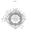
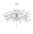
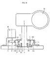
- the retainer 14 In the initial state prior to the input of rotational torque at the input outer ring 11, the retainer 14 is centered by the centering spring 15 as shown in FIG. 22. Consequently, the rollers 13 accommodated within the pockets 14a of the retainer 14 are positioned at the circumferential center points c1 of the wedge shaped gaps s1 formed between the cam surfaces 11a of the input outer ring 11 and the cylindrical section 12a of the output inner ring 12.
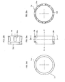
- the concave engagement members 21 can also be generated by forming circular protrusions 26a on the inner surface, as shown in FIG. 27.
- the increase in the motor current value will begin before the engagement of the engagement members 21, 22, and so reliable engagement of the engagement members 21, 22 can be ensured by stopping the motor M at the point where the current value has peaked and is beginning to decline.
- FIG. 28 shows an example in which the concave engagement members 21 are produced by forming two linear protrusions 26b which are orthogonal to the rotational direction of the convex engagement members 22.
- the mirror section of an electric retractable mirror of a vehicle was used as an example of the driven member, but provided the driven member is an object to be positioned in at least two prescribed positions, then any member can be used as the driven member.
- Suitable alternative examples include opening and closing devices (such as a door, a shutter, a sunroof, or an electric sliding door) which are opened and closed between two prescribed positions.
- the number of prescribed positions for positioning the driven member is not limited to two, and devices with three or more positions are also possible. In such cases, the number of engagement positions for the concave engagement members 21 and the convex engagement members 22 must also be increased or decreased in accordance with the number of positioning positions.
Applications Claiming Priority (7)
| Application Number | Priority Date | Filing Date | Title |
|---|---|---|---|
| JP2001065239 | 2001-03-08 | ||
| JP2001065239A JP4009429B2 (ja) | 2001-03-08 | 2001-03-08 | 逆入力防止クラッチ |
| JP2001242258 | 2001-08-09 | ||
| JP2001242232 | 2001-08-09 | ||
| JP2001242258A JP2003056602A (ja) | 2001-08-09 | 2001-08-09 | 回転駆動装置 |
| JP2001242232A JP2003056596A (ja) | 2001-08-09 | 2001-08-09 | クラッチ付き回転装置 |
| EP02251610A EP1239178B1 (de) | 2001-03-08 | 2002-03-07 | Rückwärtsfahrende Sperrkupplung |
Related Parent Applications (1)
| Application Number | Title | Priority Date | Filing Date |
|---|---|---|---|
| EP02251610A Division EP1239178B1 (de) | 2001-03-08 | 2002-03-07 | Rückwärtsfahrende Sperrkupplung |
Publications (2)
| Publication Number | Publication Date |
|---|---|
| EP1457700A1 true EP1457700A1 (de) | 2004-09-15 |
| EP1457700B1 EP1457700B1 (de) | 2006-11-02 |
Family
ID=27346195
Family Applications (2)
| Application Number | Title | Priority Date | Filing Date |
|---|---|---|---|
| EP04076428A Expired - Fee Related EP1457700B1 (de) | 2001-03-08 | 2002-03-07 | Rückwärtsfahrende Sperrkupplung |
| EP02251610A Expired - Fee Related EP1239178B1 (de) | 2001-03-08 | 2002-03-07 | Rückwärtsfahrende Sperrkupplung |
Family Applications After (1)
| Application Number | Title | Priority Date | Filing Date |
|---|---|---|---|
| EP02251610A Expired - Fee Related EP1239178B1 (de) | 2001-03-08 | 2002-03-07 | Rückwärtsfahrende Sperrkupplung |
Country Status (4)
| Country | Link |
|---|---|
| US (2) | US6695118B2 (de) |
| EP (2) | EP1457700B1 (de) |
| CN (1) | CN1288360C (de) |
| DE (2) | DE60202229T2 (de) |
Cited By (2)
| Publication number | Priority date | Publication date | Assignee | Title |
|---|---|---|---|---|
| DE102005023250A1 (de) * | 2005-04-28 | 2006-11-16 | Schaeffler Kg | Aktuator |
| WO2007113374A1 (en) * | 2006-04-04 | 2007-10-11 | Kone Corporation | Arrangement for stopping an elevator car in an emergency braking situation, and elevator |
Families Citing this family (28)
| Publication number | Priority date | Publication date | Assignee | Title |
|---|---|---|---|---|
| ATE501368T1 (de) * | 2004-05-06 | 2011-03-15 | Hans Heidolph Gmbh & Co Kg | Rückwirkungsgeschützte getriebebaueinheit und sperrkupplung |
| CN101184932B (zh) * | 2005-04-07 | 2010-05-19 | 卞东焕 | 防止反向输入的离合器轴承组件 |
| DE102005030719A1 (de) * | 2005-07-01 | 2007-01-04 | Schaeffler Kg | Klemmgesperre, insbesondere für eine Sitzverstellung |
| KR100621347B1 (ko) * | 2005-09-20 | 2006-09-07 | 주식회사 만도 | 자동차의 전기식 동력 보조 조향 장치 |
| WO2007087927A1 (de) * | 2006-01-31 | 2007-08-09 | Schaeffler Kg | Fensterheberantrieb |
| KR100778560B1 (ko) | 2006-10-16 | 2007-11-22 | 현대자동차주식회사 | 차량 사이드 미러의 구동 시스템 및 구동 방법 |
| DE102007017617B4 (de) * | 2006-11-02 | 2016-06-09 | Johnson Controls Gmbh | Verstelleinrichtung eines Kraftfahrzeugsitzes |
| CN100552250C (zh) * | 2007-03-16 | 2009-10-21 | 蔡国法 | 单向离合器 |
| DE112008003234T5 (de) * | 2007-12-12 | 2010-10-14 | NTN Corporation, Osaka-shi | Drehungs-Übertragungsvorrichtung |
| JP5185209B2 (ja) * | 2009-06-09 | 2013-04-17 | オリジン電気株式会社 | 逆入力遮断クラッチ |
| US8950565B2 (en) | 2010-06-22 | 2015-02-10 | Rotork Controls Limited | Anti back-drive couplings |
| HRP20211814T1 (hr) * | 2010-07-16 | 2022-03-04 | Eltorque As | Samo-zaključavajući mehanizam za aktuator ventila |
| US8852041B2 (en) * | 2010-09-30 | 2014-10-07 | Shimano, Inc. | Bicycle derailleur with rotation resistance |
| US8870692B2 (en) * | 2010-09-30 | 2014-10-28 | Shimano, Inc. | Bicycle derailleur with rotation resistance |
| DE102011084397A1 (de) * | 2011-10-13 | 2013-04-18 | Schaeffler Technologies AG & Co. KG | Freilauf |
| NL1039622C2 (nl) * | 2012-05-23 | 2013-11-26 | Forest Group Nederland Bv | Vrijloop-koppeling. |
| EP2698280B1 (de) * | 2012-08-14 | 2015-08-19 | Fico Mirrors, S.A. | Faltspiegel mit Doppelarretierung |
| JP6065505B2 (ja) * | 2012-10-03 | 2017-01-25 | 株式会社ジェイテクト | 発電装置 |
| KR101450625B1 (ko) * | 2013-01-25 | 2014-10-15 | 삼성중공업 주식회사 | 트롤리 |
| WO2015012211A1 (ja) * | 2013-07-25 | 2015-01-29 | トヨタ自動車 株式会社 | クラッチ |
| JP2015206455A (ja) * | 2014-01-28 | 2015-11-19 | Ntn株式会社 | ブレーキ付減速機 |
| JP6157720B2 (ja) * | 2014-03-14 | 2017-07-05 | オリジン電気株式会社 | 逆入力遮断クラッチ |
| DE102014212863B4 (de) * | 2014-07-02 | 2020-08-20 | Stabilus Gmbh | Klappensteuerung |
| NL2018838B1 (nl) * | 2017-05-03 | 2018-11-14 | Mci Mirror Controls Int Netherlands B V | Verstelinstrument en werkwijze |
| CN110848284A (zh) * | 2018-08-20 | 2020-02-28 | 锅屋百泰株式会社 | 带反向输入阻断离合器的电动机及反向输入阻断离合器 |
| WO2020133269A1 (zh) * | 2018-12-28 | 2020-07-02 | 深圳配天智能技术研究院有限公司 | 一种限位装置、机械臂及机器人 |
| US10711852B1 (en) * | 2019-01-18 | 2020-07-14 | General Electric Company | Locking clutch systems |
| CN112555293A (zh) * | 2020-12-21 | 2021-03-26 | 上海探见智能家居有限公司 | 一种开窗器离合器 |
Citations (3)
| Publication number | Priority date | Publication date | Assignee | Title |
|---|---|---|---|---|
| EP0884494A1 (de) * | 1997-06-02 | 1998-12-16 | Ichikoh Industries Limited | Blockiermechanismus |
| WO2000041914A1 (en) * | 1999-01-11 | 2000-07-20 | Schefenacker Vision Systems Australia Pty Ltd | A mirror rotation mechanism |
| US6132050A (en) * | 1993-09-03 | 2000-10-17 | Ichikoh Industries, Ltd. | Rearview mirror system for vehicles |
Family Cites Families (24)
| Publication number | Priority date | Publication date | Assignee | Title |
|---|---|---|---|---|
| US2260119A (en) * | 1940-06-28 | 1941-10-21 | Briggs Mfg Co | Clutch assembly |
| US2449020A (en) * | 1943-06-14 | 1948-09-07 | Automatic Locking Devices Inc | Power drive |
| US2561159A (en) * | 1944-09-14 | 1951-07-17 | Cecil E Walton | Self-locking clutch |
| US3011606A (en) * | 1957-07-26 | 1961-12-05 | Borg Warner | Roller clutch |
| US3005384A (en) * | 1960-08-17 | 1961-10-24 | Royal Engineering Co Inc | Power actuated rear view mirror |
| GB1174226A (en) * | 1968-01-17 | 1969-12-17 | Schaeffler Ohg Industriewerk | Improvements in Jamming-Roller Freewheel Clutches |
| US4070895A (en) * | 1975-09-20 | 1978-01-31 | Tokico Ltd. | Method for manufacturing bottom valve seat |
| US4676089A (en) * | 1985-05-13 | 1987-06-30 | Nevin Donald M | Hub for rotatable tool |
| FR2621965B1 (fr) * | 1987-10-09 | 1995-06-09 | Ntn Toyo Bearing Co Ltd | Embrayage notamment pour direction assistee electriquement |
| JPH01218729A (ja) * | 1988-02-29 | 1989-08-31 | Sanden Corp | 電磁クラッチ用ローター本体の製造方法 |
| DE3839732A1 (de) | 1988-11-24 | 1990-06-07 | Rentrop Hubbert & Wagner | Bremse fuer ein verstellgetriebe von kraftfahrzeugsitzen |
| JPH0712509B2 (ja) * | 1990-04-17 | 1995-02-15 | 日本精工株式会社 | アウトサイドリングの製造方法 |
| DE9101110U1 (de) * | 1991-02-01 | 1992-02-27 | Schwarzbich, Joerg, 4800 Bielefeld, De | |
| JP2602999Y2 (ja) * | 1991-12-26 | 2000-02-07 | 株式会社村上開明堂 | 電動格納ドアミラーの制御装置 |
| DE9319848U1 (de) * | 1993-12-23 | 1995-01-26 | Schwarzbich Joerg | Sitzverstellung |
| DE4447480A1 (de) | 1994-12-24 | 1996-06-27 | Schaeffler Waelzlager Kg | Vorzugsweise für eine Sitzverstellung vorgesehenes Klemmgesperre |
| US5703732A (en) * | 1995-01-17 | 1997-12-30 | Lowell Engineering Corporation | Exterior mirror with indexing and control pivoting |
| JP3516315B2 (ja) * | 1995-07-05 | 2004-04-05 | 本田技研工業株式会社 | 電動パワーステアリング装置 |
| FR2766773B1 (fr) * | 1997-07-30 | 1999-10-15 | Faure Bertrand Equipements Sa | Dispositif de blocage notamment pour siege de vehicule automobile |
| DE29715257U1 (de) * | 1997-08-26 | 1997-12-04 | Atlas Copco Electric Tools | Mitnahmevorrichtung |
| US5952802A (en) * | 1997-12-08 | 1999-09-14 | Delco Electronics Corp. | Method of controlling an automotive mirror |
| DE19854945A1 (de) * | 1998-11-27 | 2000-05-31 | Schaeffler Waelzlager Ohg | Klemmrollenschaltwerk |
| US6267218B1 (en) * | 1999-03-12 | 2001-07-31 | INA Wälzlager Schaeffler oHG | Clamp-type locking mechanism |
| US6508374B1 (en) * | 1999-11-04 | 2003-01-21 | Stant Manufacturing Inc. | Filler neck closure with static charge dissipater |
-
2002
- 2002-03-07 DE DE60202229T patent/DE60202229T2/de not_active Expired - Lifetime
- 2002-03-07 EP EP04076428A patent/EP1457700B1/de not_active Expired - Fee Related
- 2002-03-07 EP EP02251610A patent/EP1239178B1/de not_active Expired - Fee Related
- 2002-03-07 DE DE60215854T patent/DE60215854T2/de not_active Expired - Lifetime
- 2002-03-07 US US10/091,593 patent/US6695118B2/en not_active Expired - Lifetime
- 2002-03-08 CN CNB021067767A patent/CN1288360C/zh not_active Expired - Fee Related
-
2003
- 2003-11-10 US US10/703,490 patent/US7117710B2/en not_active Expired - Lifetime
Patent Citations (3)
| Publication number | Priority date | Publication date | Assignee | Title |
|---|---|---|---|---|
| US6132050A (en) * | 1993-09-03 | 2000-10-17 | Ichikoh Industries, Ltd. | Rearview mirror system for vehicles |
| EP0884494A1 (de) * | 1997-06-02 | 1998-12-16 | Ichikoh Industries Limited | Blockiermechanismus |
| WO2000041914A1 (en) * | 1999-01-11 | 2000-07-20 | Schefenacker Vision Systems Australia Pty Ltd | A mirror rotation mechanism |
Cited By (4)
| Publication number | Priority date | Publication date | Assignee | Title |
|---|---|---|---|---|
| DE102005023250A1 (de) * | 2005-04-28 | 2006-11-16 | Schaeffler Kg | Aktuator |
| DE102005023250B4 (de) * | 2005-04-28 | 2017-10-05 | Schaeffler Technologies AG & Co. KG | Aktuator |
| WO2007113374A1 (en) * | 2006-04-04 | 2007-10-11 | Kone Corporation | Arrangement for stopping an elevator car in an emergency braking situation, and elevator |
| US9038781B2 (en) | 2006-04-04 | 2015-05-26 | Kone Corporation | Elevator and arrangement for emergency stopping an elevator car |
Also Published As
| Publication number | Publication date |
|---|---|
| US20040089049A1 (en) | 2004-05-13 |
| EP1239178B1 (de) | 2004-12-15 |
| CN1288360C (zh) | 2006-12-06 |
| EP1239178A2 (de) | 2002-09-11 |
| DE60215854D1 (de) | 2006-12-14 |
| DE60202229D1 (de) | 2005-01-20 |
| DE60202229T2 (de) | 2005-12-15 |
| EP1457700B1 (de) | 2006-11-02 |
| EP1239178A3 (de) | 2002-10-02 |
| US6695118B2 (en) | 2004-02-24 |
| CN1374465A (zh) | 2002-10-16 |
| DE60215854T2 (de) | 2007-06-28 |
| US20020125099A1 (en) | 2002-09-12 |
| US7117710B2 (en) | 2006-10-10 |
Similar Documents
| Publication | Publication Date | Title |
|---|---|---|
| EP1239178B1 (de) | Rückwärtsfahrende Sperrkupplung | |
| US4852707A (en) | Reversible self-locking clutch | |
| US8256699B2 (en) | Webbing take-up device | |
| JP7052529B2 (ja) | アクチュエータ及びステアバイワイヤ式操舵装置 | |
| EP2055530A2 (de) | Motorbetriebener Aktuator | |
| KR101436944B1 (ko) | 자가 조정 브레이크를 갖는 차량 시트용 조정 장치 | |
| US20090309345A1 (en) | Device for restraining a vehicle occupant | |
| US6805361B2 (en) | Stabilizer arrangement for a motor vehicle | |
| JP2003276565A (ja) | 電動ステアリングロック装置 | |
| JP4009429B2 (ja) | 逆入力防止クラッチ | |
| JP7060169B2 (ja) | 逆入力遮断クラッチ | |
| US6748774B2 (en) | Forward firing shaft lock mechanism | |
| US20210088126A1 (en) | Electromechanical power steering having a helical-gear transmission and a transmission housing | |
| WO2020207900A1 (de) | Torquetransistor und e-bike mit torquetransistor | |
| JP2003056596A (ja) | クラッチ付き回転装置 | |
| CN212509395U (zh) | 一种凸轮机构及驻车装置 | |
| JPH0747961A (ja) | 衝撃吸収式ステアリング装置 | |
| JP2008062932A (ja) | 電動パワーステアリング装置の減速機構 | |
| JP2019031290A (ja) | ステアリング装置 | |
| JP2008179170A (ja) | 車両用操舵装置 | |
| JP4051998B2 (ja) | 電動パワーステアリング装置の減速機構 | |
| JP2007507678A (ja) | 移動可能な連結素子及び操作器を持つ遊星歯車装置 | |
| JP2000234971A (ja) | トルクセンサ及び同トルクセンサを備えた電動パワーステアリング装置 | |
| JPH09109903A (ja) | ステアリング機構 | |
| JP2008308054A (ja) | 車両用操舵装置 |
Legal Events
| Date | Code | Title | Description |
|---|---|---|---|
| PUAI | Public reference made under article 153(3) epc to a published international application that has entered the european phase |
Free format text: ORIGINAL CODE: 0009012 |
|
| 17P | Request for examination filed |
Effective date: 20040525 |
|
| AC | Divisional application: reference to earlier application |
Ref document number: 1239178 Country of ref document: EP Kind code of ref document: P |
|
| AK | Designated contracting states |
Kind code of ref document: A1 Designated state(s): DE FR GB |
|
| AKX | Designation fees paid |
Designated state(s): DE FR GB |
|
| GRAP | Despatch of communication of intention to grant a patent |
Free format text: ORIGINAL CODE: EPIDOSNIGR1 |
|
| GRAS | Grant fee paid |
Free format text: ORIGINAL CODE: EPIDOSNIGR3 |
|
| GRAA | (expected) grant |
Free format text: ORIGINAL CODE: 0009210 |
|
| AC | Divisional application: reference to earlier application |
Ref document number: 1239178 Country of ref document: EP Kind code of ref document: P |
|
| AK | Designated contracting states |
Kind code of ref document: B1 Designated state(s): DE FR GB |
|
| RIN1 | Information on inventor provided before grant (corrected) |
Inventor name: KURITA, MASAHIRO Inventor name: KAWAI, MASAHIRO Inventor name: YOSHIOKA, ATSUSHI |
|
| REG | Reference to a national code |
Ref country code: GB Ref legal event code: FG4D |
|
| REF | Corresponds to: |
Ref document number: 60215854 Country of ref document: DE Date of ref document: 20061214 Kind code of ref document: P |
|
| ET | Fr: translation filed | ||
| PLBE | No opposition filed within time limit |
Free format text: ORIGINAL CODE: 0009261 |
|
| STAA | Information on the status of an ep patent application or granted ep patent |
Free format text: STATUS: NO OPPOSITION FILED WITHIN TIME LIMIT |
|
| 26N | No opposition filed |
Effective date: 20070803 |
|
| REG | Reference to a national code |
Ref country code: FR Ref legal event code: PLFP Year of fee payment: 15 |
|
| REG | Reference to a national code |
Ref country code: FR Ref legal event code: PLFP Year of fee payment: 16 |
|
| REG | Reference to a national code |
Ref country code: FR Ref legal event code: PLFP Year of fee payment: 17 |
|
| PGFP | Annual fee paid to national office [announced via postgrant information from national office to epo] |
Ref country code: GB Payment date: 20190306 Year of fee payment: 18 Ref country code: DE Payment date: 20190219 Year of fee payment: 18 |
|
| PGFP | Annual fee paid to national office [announced via postgrant information from national office to epo] |
Ref country code: FR Payment date: 20190213 Year of fee payment: 18 |
|
| REG | Reference to a national code |
Ref country code: DE Ref legal event code: R119 Ref document number: 60215854 Country of ref document: DE |
|
| PG25 | Lapsed in a contracting state [announced via postgrant information from national office to epo] |
Ref country code: DE Free format text: LAPSE BECAUSE OF NON-PAYMENT OF DUE FEES Effective date: 20201001 Ref country code: FR Free format text: LAPSE BECAUSE OF NON-PAYMENT OF DUE FEES Effective date: 20200331 |
|
| GBPC | Gb: european patent ceased through non-payment of renewal fee |
Effective date: 20200307 |
|
| PG25 | Lapsed in a contracting state [announced via postgrant information from national office to epo] |
Ref country code: GB Free format text: LAPSE BECAUSE OF NON-PAYMENT OF DUE FEES Effective date: 20200307 |