EP1456621B1 - Procede de determination de puissance, dispositif de mesure et banc d'essai de puissance pour specimen d'essai - Google Patents
Procede de determination de puissance, dispositif de mesure et banc d'essai de puissance pour specimen d'essai Download PDFInfo
- Publication number
- EP1456621B1 EP1456621B1 EP02795113.6A EP02795113A EP1456621B1 EP 1456621 B1 EP1456621 B1 EP 1456621B1 EP 02795113 A EP02795113 A EP 02795113A EP 1456621 B1 EP1456621 B1 EP 1456621B1
- Authority
- EP
- European Patent Office
- Prior art keywords
- test specimen
- internal combustion
- combustion engine
- power
- test
- Prior art date
- Legal status (The legal status is an assumption and is not a legal conclusion. Google has not performed a legal analysis and makes no representation as to the accuracy of the status listed.)
- Expired - Lifetime
Links
Images
Classifications
-
- G—PHYSICS
- G01—MEASURING; TESTING
- G01M—TESTING STATIC OR DYNAMIC BALANCE OF MACHINES OR STRUCTURES; TESTING OF STRUCTURES OR APPARATUS, NOT OTHERWISE PROVIDED FOR
- G01M15/00—Testing of engines
-
- G—PHYSICS
- G01—MEASURING; TESTING
- G01M—TESTING STATIC OR DYNAMIC BALANCE OF MACHINES OR STRUCTURES; TESTING OF STRUCTURES OR APPARATUS, NOT OTHERWISE PROVIDED FOR
- G01M15/00—Testing of engines
- G01M15/04—Testing internal-combustion engines
- G01M15/042—Testing internal-combustion engines by monitoring a single specific parameter not covered by groups G01M15/06 - G01M15/12
- G01M15/046—Testing internal-combustion engines by monitoring a single specific parameter not covered by groups G01M15/06 - G01M15/12 by monitoring revolutions
-
- G—PHYSICS
- G01—MEASURING; TESTING
- G01M—TESTING STATIC OR DYNAMIC BALANCE OF MACHINES OR STRUCTURES; TESTING OF STRUCTURES OR APPARATUS, NOT OTHERWISE PROVIDED FOR
- G01M15/00—Testing of engines
- G01M15/04—Testing internal-combustion engines
- G01M15/042—Testing internal-combustion engines by monitoring a single specific parameter not covered by groups G01M15/06 - G01M15/12
- G01M15/044—Testing internal-combustion engines by monitoring a single specific parameter not covered by groups G01M15/06 - G01M15/12 by monitoring power, e.g. by operating the engine with one of the ignitions interrupted; by using acceleration tests
-
- F—MECHANICAL ENGINEERING; LIGHTING; HEATING; WEAPONS; BLASTING
- F02—COMBUSTION ENGINES; HOT-GAS OR COMBUSTION-PRODUCT ENGINE PLANTS
- F02D—CONTROLLING COMBUSTION ENGINES
- F02D2200/00—Input parameters for engine control
- F02D2200/02—Input parameters for engine control the parameters being related to the engine
- F02D2200/10—Parameters related to the engine output, e.g. engine torque or engine speed
- F02D2200/1015—Engines misfires
Definitions
- the invention relates to a method for determining the performance of a test object, for example an internal combustion engine, with a dynamometer.
- the real load conditions are often realized by a load simulating brake motor or a brake
- the brake motor or the brake usually acts on the output shaft of the specimen and also must have about the same power size and capability as the test specimen to the performance of the specimen to be able to test.
- electric motors are designed as brake motors whose power consumption is used to determine the power.
- brake drives eddy current brakes are known in addition to electric motors.
- test object that is, for example, the connection of the media supply systems to the test object, such as control lines, fuel supply and cooling water supply. Thereafter, a comparatively long time is spent on the load test itself, which typically takes about 20 to 30 minutes for the automotive engine to obtain the required power levels. This represents a considerable effort.
- the inventive method for determining the power of a test specimen requires a measuring device for detecting the time course of the rotational speed of an output shaft of the specimen, wherein for determining the power at a given time excluding the time course of the rotational speed is measured, and wherein the test specimen is tested within such a period in which there is no need for forced cooling, that is, the heat generated during operation loss is mainly absorbed by the test specimen due to its heat capacity and partly by radiation and Convection heat released back to the environment.
- a significant advantage of the method according to the invention for determining the power of the test specimen is that only the speed in connection with the time as Measured variables are measured, whereby the instrumentation and Meßaufwand is considerably reduced in comparison to the previously known methods.
- the period within which the test is carried out is advantageously short. Namely, the performance test is carried out in such a short time that the heat loss resulting from the combustion is predominantly absorbed by the test object, but without overheating in an undue manner, that is to say that during the performance test no operating states are reached which over-test the test object wear out or even damage. Mainly the heat capacity of the test piece is used to absorb the waste heat. Accordingly, it is no longer necessary to connect a device for forced cooling to the test object for the duration of the power measurement. Overall, according to the invention, the test time of a typical reciprocating internal combustion engine of a motor vehicle can be shortened to about 1 minute.
- P (t) is the power P at the particular instant (t), where I is the moment of inertia of the total mass of the sample moved or accelerated, a (t) being the angular acceleration at the particular instant (t), where M friction is the friction torque is the total rotational mass moved by the test specimen, which counteracts the rotary motion or spin, and w (t) is the angular velocity at the particular time (t).
- the power depends only on the speed and the time, thus advantageously simple, the speed itself is already a time-dependent variable.
- the speed itself is already a time-dependent variable.
- the angular velocity ie the time derivative of the speed
- the angular acceleration ie the time derivative of the angular velocity
- the results of the power determination are improved if the moment of inertia is indeed assumed to be constant, but the friction torque is inserted into the formula after a friction-torque curve that was previously determined specifically for the type of test specimen and is dependent on the rotational speed. Accordingly, the friction torque is dependent on the speed.
- This dependence can be derived, for example, according to the generally known physical laws or can be determined empirically by means of measurements for the type of test object concerned. The determined friction torque curve is then stored and is available for the calculation of the line points.
- the test object is tested in a test stand set up for this type of performance test.
- the test bench is optimally adapted to the test conditions and offers in this way correspondingly favorable test conditions.
- the test object is incorporated or included when it reaches a predetermined speed for automatic operation. If particularly favorable starting conditions prevail, the specified speed will be the predefinable speed. In principle, however, a minimum speed is sufficient as a specified speed at which the device under test can just be started. The advantage of this is that a required to achieve the specified speed starter can be designed to be particularly small.
- a possible method step according to the invention provides that the starter is switched off after reaching the specific speed or when the device under test is running in automatic mode. That is, the test specimen gives off power and thus drives its output shaft already automatically when the starter is turned off. This avoids influencing the power measurement by means of a further active drive or brake drive.
- this type of power measurement according to the invention that is a particular advantage of the invention. Accordingly, in particular the rotor of the starter turns, as already explained without self-propulsion, but driven by the test specimen. In this case, the mass moment of inertia of the rotating masses of the starter must be taken into account when calculating the total mass moment of inertia.
- the starter can also be decoupled from the test specimen. Then its rotational mass is not taken into account in the calculation of the total mass moment of inertia.
- the test specimen can advantageously be accelerated or speeded up quickly.
- the test object is accelerated in its own mode to a maximum rated speed. This achieves a comparatively short test time.
- test time is further shortened if the acceleration takes place with specification of a full load value for the rotational speed.
- the test time is then advantageously minimized.
- a further embodiment of the method according to the invention provides that a number of powers of the test object are determined at fixed speed values, that the power points between the measured speeds are connected by an interpolation method, in particular a linear one, and that the power curve determined in this way is dependent on the speed and optionally the measured values are stored.
- a power point for example, the maximum power or a single power at the desired operating point to obtain a power curve, for example, because the performance characteristics of a car engine to be determined. This is advantageously achieved by the method steps just described.
- a further development of the method according to the invention provides that the measured values are recorded by an evaluation device and optionally graphically displayed and provided for further data processing. Accordingly, the evaluation device displays both the measured data and the data evaluation in the form of stored result data or already as graphics. Thus, the quality of the test object can be recognized by a first visual inspection. Also, based on the measured data and the result data, it becomes possible to automate the control of whether the performance test was successful.
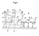
- Fig. 1 shows a sectional view of a dynamometer 10.
- a frame 12 on which a table device 14 is arranged.
- a starter device 16 is arranged, to which by means of a coupling 18, a coupling and testing device 20 is connected.
- the coupling 18 is rigid in this embodiment, so that the starter device 16 and the coupling and testing device 20 in the coupled state form a starter unit.
- the coupling and testing device 20 can be coupled to a test piece 26.
- the coupling is undamped. In this way, the performance, in particular the performance in the test mode of the DUT 26 is transmitted as directly as possible to the coupling and testing device 20.
- the DUT 26 is a 4-cylinder 4-stroke in-line engine.
- any other power output combustion engine comes into consideration, such as two-stroke, diesel engines and turbines.
- the coupling and testing device 20 in this example has an incremental encoder with 2500 increments per 360 degrees, a signal conditioning and a data acquisition device with a data acquisition rate of at least 200 kHz.
- all signal pickups are mounted on the starter and test apparatus 20, which are for detecting the measured values, which reach via a shaft 22 in the starter and test apparatus 20 and should be recorded.
- the evaluation device is in the example shown, a data processing system in the form of a personal computer (PC), which is not shown in the figure and is connected via a signal line, also not shown with the starter and tester 20. The evaluation takes over the evaluation of the dynamometer 10, short test bench 10 obtained measurement data.
- PC personal computer
- the in-line motor 26 can be lifted out of a transport system not shown in the figure and is moved to the test position on the test bench.
- a transport system for example, today is a common driverless single transport system into consideration.
- any continuous or discontinuous conveying system suitable for the inline engine 26 or the test piece 26 is readily usable.
- the test stand 10 according to the invention is structurally adaptable in a simple manner to the relevant circumstances.
- two screw devices 24 are movably arranged on the frame 12, of which only one is visible in this figure, which release the row motor 26 mounted on the transport device.
- the lifting device 23 spends the in-line motor 26 in a test position in a first 42 and a second holding device 50 to fix the in-line motor in the test position by sliding them against each other from two sides in a horizontal plane and the in-line motor 26 located between the holders 42, 50 in such a way is jammed and held.
- the holders 42, 50 only the first holder 42 is shown in this figure. However, the operation of both holding devices 42, 50 in the FIG. 2 recognizable.
- a multi-coupling device 28 is provided to connect a not shown fuel supply line with a fuel system of the series engine 26 and electrical supply, control and Signal lines with the corresponding lines of the series motor 26 to connect.
- the multi-coupling device 28 is movable in three spatial directions in order to connect to the corresponding coupling point on the series motor 26 can.
- a sealing device 30 can be connected to an exhaust system of the in-line engine 26 in a tight-fitting manner, whereby exhaust gases of the series engine 26 produced during operation are directed away from the test bench 10 via an exhaust pipe not shown in the figure.
- the sealing device 30, comparable to the multi-coupling device 28, is movable in the three spatial directions.
- a hold-down 32 is movably disposed on an upper cross member 34 of the frame 12, wherein the hold-down 32 is provided for additional fixing of the series motor 26, in particular during the test operation. This is moved vertically from above to the series motor 26 and acted upon by a predetermined force, so braced.
- the in-line engine 26 is transported to the test stand 10 and brought into a designated unloading in area of the frame 12. With the two opposite screwing 24 first the series motor 26 is released from a transport bracket.
- the lifting device 23 is located below the unloading position and is now moved substantially upwards, lifting the in-line motor 26 from the transport device into a test position. In this example, the transport device remains in the unloading position in the test stand 10. It is also conceivable that this is moved to a parking position outside the test bench area.
- the holding devices 42, 50 of the series motor 26 With the holding devices 42, 50 of the series motor 26 is firmly clamped in the test position, that is, that the holding devices 42, 50, the series engine 26 in one apply a predetermined force to the horizontal direction.
- the lifting device 23 prevents the in-line motor 26 can be moved down.
- test object 26 or the series motor 26 is now firmly connected to the test stand 10 or braced against the frame 12.
- the hold-down 32 is moved from above against the in-line motor 26 in a predetermined position and so the series motor 26 braced against the test bed 10 and the lifting device 23.
- an additional fixation of the series motor 26 is achieved, which is then held in two places in the horizontal direction and from above and below at two other locations in the vertical direction accordingly.
- the multi-coupling device 28 connects to the counter-coupling provided for this purpose or to a corresponding point on the in-line motor 26.
- the sealing device 30 is connected to the exhaust system of the series engine 26.
- connection of the sealing device 30 can take place in parallel with the time of the connection of the multi-coupling device 28, provided that the movements of the device do not interfere with one another.
- the processes at the test bench 10 and the performance test are controlled and measured with a measuring and control device, which is not shown in the figure, but is connected by means of appropriate control and signal cables to the various devices of the test bench 10.
- a measuring and control device which is not shown in the figure, but is connected by means of appropriate control and signal cables to the various devices of the test bench 10.
- the series engine 26 is first with the coupled via the coupling and testing device 20 starter device 16 to a Idle speed of about 850 revolutions per minute (rpm) accelerated.
- Automotive engines have idling speeds of usually about 450 to 1000 U / min.
- the starter device 16 only needs to be designed for a comparatively low power. Namely, the starter device 16 has to perform only the lugging up of the in-line engine 26 up to the idle speed and then it is not further active, that is, for example, as a brake involved in the determination of the power. The usual driving in the same size as the DUT are advantageously avoided.
- the power detection measurement process may begin by accelerating the in-line engine 26 to full throttle at its maximum rated speed. This process is repeated 4 more times. During the entire trial period, the time profile of the rotational speed of the output shaft of the series engine 26 is detected by the measuring and control device. Acceleration from idle speed to maximum rated speed takes 12 seconds in this example. With the repetitions, the entire performance test lasts only 90 seconds. This is a period of time that the series engine 26 can be operated without any external cooling, that is, for example, without cooling water.
- the achievement of the comparatively short test time is also aided by the fact that the in-line motor 26 is not burdened by a load corresponding to its own power, such as an eddy current brake, as in the prior art, in order to obtain the power curve, but only becomes accelerates the rotating masses connected to the output shaft, that is, brought up to the maximum speed to perform the power measurement.
- a load corresponding to its own power such as an eddy current brake, as in the prior art
- the angular velocity and the angular acceleration for a number of fixed speeds is first calculated, for example, for each speed between idle speed and maximum rated speed in steps of 100 rev / min.
- the power is now determined by calculating the sum of a first multiplication of the constant total mass moment of inertia with the number 100 and with the angular acceleration to the determined speed and a second multiplication of a constant friction torque with the angular speed at the determined speed.
- the total mass moment of inertia is a constant which results from the sum of the individual mass moments of inertia of the rotating elements and device parts involved in the measurement, in this example the moments of inertia of the moving shafts of the series engine 26, the rotating parts of the measuring and coupling device 20 and moving shaft with rotor of the starter device 16, which is an electric motor here and should not be decoupled from the series engine 26 during the performance test.
- the measured values serve as the basis for the calculation. The calculation becomes better, the more accurately the time course of the speed is determined.
- an incremental encoder with 2500 increments per 360 degrees is installed in the measuring and coupling device 20.
- the measured data are detected with a measuring card having a data acquisition rate of greater than 200 kHz.
- the measuring and Control device is configured as a personal computer (PC), which takes over both the measured value and the measurement data evaluation, as well as the control and regulation of scholarvor- and post-processing and the coordination of the movements of the devices for connection and release of the series motor 26 after the power measurement.
- PC personal computer
- measured values were measured or calculated engine performance, which have only an inaccuracy + 3% or -2%. In any case, without further compliance with the usual requirements for the accuracy of +/- 5% without further ado.
- an interpolation method is recommended. If the measurement and calculation points are set in sufficient numbers, a linear interpolation method is usually sufficient to arrive at sufficient result curves. However, given polynomials can also be used as the basis for interpolation.
- the in-line motor 26 is turned off and can be released from the test stand 10, that is, the sealing device 30, the multi-coupling device 28 and the hold-down device 32 are removed from the test piece.
- the holding devices 24 move back to a starting position and thus solve the fixation of the series engine 26. Are all connections with the devices of the test stand 26 solved, this is still supported by the lifting device, which spends the in-line engine away from the test position and back to the transport means.
- the series motor 26 is again mounted on the transport device or its transport on this secured, so that the further transport to a point at which a next production step is provided, can take place.
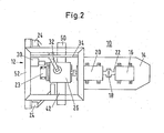
- Fig. 2 shows a plan view of the dynamometer 10. In this figure, those components have been provided with the same reference numerals already in the Fig. 1 were introduced and also shown in this figure.
- this view shows that the frame 12 is formed like a frame in a horizontal plane 52.
- the screwing devices 24 are arranged opposite each other on two sides of the frame.
- the starter unit of starter supply 16, clutch 18 and measuring and coupling device 20 is arranged on the table device 14.
- the in-line motor 26 is shown in its test position and was spent on the fourth side in the test bench 10.
- This preferred arrangement of the various devices on the test bed 10 has the particular advantage that they are arranged particularly clear and accessible. Therefore, possible disturbances can often be detected at a first control glance.
- the test stand 10 can be easily integrated into the production process because it is completely accessible from one side.
Landscapes
- Physics & Mathematics (AREA)
- General Physics & Mathematics (AREA)
- Chemical & Material Sciences (AREA)
- Engineering & Computer Science (AREA)
- Combustion & Propulsion (AREA)
- Testing Of Engines (AREA)
Claims (8)
- Procédé de détermination de puissance d'un moteur à combustion interne (spécimen d'essai) (26), avec un dispositif de mesure pour détecter la courbe dans le temps de la vitesse de rotation d'un arbre d'entraînement en sortie du moteur à combustion interne (spécimen d'essai) (26), seule la courbe dans le temps de la vitesse de rotation étant mesurée pour déterminer la puissance à un instant défini et le moteur à combustion interne (spécimen d'essai) (26) étant contrôlé à l'intérieur d'un intervalle de temps ne présentant aucune nécessité de refroidissement contraint, aucun dispositif de refroidissement contraint n'étant raccordé et la puissance du spécimen d'essai à un instant défini étant calculé selon la formule :

où :P(t) = puissance P à l'instant défini (t) ;I = moment d'inertie de masse de la masse en rotation totale déplacée et/ou accélérée par le moteur à combustion interne (spécimen d'essai) (26) ;α(t) = accélération angulaire à l'instant défini (t) ; Mreib = moment de frottement de la masse en rotation totale déplacée par le moteur à combustion interne (spécimen d'essai) (26) agissant contre le mouvement de rotation et/ou l'accélération de rotation ; etω(t) = vitesse angulaire à l'instant défini (t) ; et le moment d'inertie de masse prenant la forme d'une constante et le moment de frottement déterminé d'après une courbe de moment de frottement spécifiquement déterminée au préalable pour le type de moteur à combustion interne (spécimen d'essai) (26), en fonction de la vitesse de rotation, étant utilisé dans la formule. - Procédé selon la revendication 1, caractérisé en ce que le moteur à combustion interne (spécimen d'essai) (26) est entraîné par un démarreur (16) jusqu'à atteindre une vitesse de rotation prédéfinie spécifique au moteur à combustion interne (spécimen d'essai) (26).
- Procédé selon la revendication 1 ou 2, caractérisé en ce que le moteur à combustion interne (spécimen d'essai) (26) est démarré lorsqu'une vitesse de rotation déterminée permettant un fonctionnement automatique est atteinte.
- Procédé selon l'une quelconque des revendications précédentes, caractérisé en ce que le démarreur (16) est déconnecté une fois que la vitesse de rotation définie est atteinte ou lorsque le moteur à combustion interne (spécimen d'essai) (26) tourne en fonctionnement autonome.
- Procédé selon l'une quelconque des revendications précédentes, caractérisé en ce que le démarreur (16) est découplé par le moteur à combustion interne (spécimen d'essai) (26).
- Procédé selon l'une quelconque des revendications précédentes, caractérisé en ce que le moteur à combustion interne (spécimen d'essai) (26) est accéléré en fonctionnement autonome jusqu'à une vitesse de rotation nominale maximale.
- Procédé selon la revendication 6, caractérisé en ce que l'accélération se produit dans le cadre d'une directive de valeur de pleine charge pour la vitesse de rotation.
- Procédé selon l'une quelconque des revendications précédentes, caractérisé en ce qu'un nombre de valeurs de puissance du moteur à combustion interne (spécimen d'essai) (26) est calculé pour des valeurs de vitesse de rotation fixes, que les points de puissance entre les vitesses de rotation mesurées sont reliés par un procédé d'interpolation, notamment linéaire, et que la courbe de puissance ainsi calculée est mémorisée en fonction de la vitesse de rotation ainsi que le cas échéant des valeurs de mesure.
Applications Claiming Priority (3)
| Application Number | Priority Date | Filing Date | Title |
|---|---|---|---|
| DE10162786A DE10162786B4 (de) | 2001-12-20 | 2001-12-20 | Verfahren zur Leistungsermittlung, Messvorrichtung und Leistungsprüfstand für einen Prüfling |
| DE10162786 | 2001-12-20 | ||
| PCT/EP2002/013824 WO2003054502A1 (fr) | 2001-12-20 | 2002-12-06 | Procede de determination de puissance, dispositif de mesure et banc d'essai de puissance pour specimen d'essai |
Publications (2)
| Publication Number | Publication Date |
|---|---|
| EP1456621A1 EP1456621A1 (fr) | 2004-09-15 |
| EP1456621B1 true EP1456621B1 (fr) | 2015-06-03 |
Family
ID=7710059
Family Applications (1)
| Application Number | Title | Priority Date | Filing Date |
|---|---|---|---|
| EP02795113.6A Expired - Lifetime EP1456621B1 (fr) | 2001-12-20 | 2002-12-06 | Procede de determination de puissance, dispositif de mesure et banc d'essai de puissance pour specimen d'essai |
Country Status (8)
| Country | Link |
|---|---|
| US (2) | US7096746B2 (fr) |
| EP (1) | EP1456621B1 (fr) |
| JP (1) | JP2005525537A (fr) |
| KR (1) | KR20040068948A (fr) |
| CN (1) | CN100565163C (fr) |
| BR (1) | BR0215171B1 (fr) |
| DE (1) | DE10162786B4 (fr) |
| WO (1) | WO2003054502A1 (fr) |
Families Citing this family (31)
| Publication number | Priority date | Publication date | Assignee | Title |
|---|---|---|---|---|
| DE10162787B4 (de) * | 2001-12-20 | 2007-08-16 | Abb Patent Gmbh | Verfahren zur Leistungsermittlung und Leistungsprüfstand für einen Prüfling |
| DE10162786B4 (de) * | 2001-12-20 | 2007-08-23 | Abb Patent Gmbh | Verfahren zur Leistungsermittlung, Messvorrichtung und Leistungsprüfstand für einen Prüfling |
| DE60330196D1 (de) * | 2003-12-12 | 2009-12-31 | Hirata Spinning | Testvorrichtung des motorantriebs |
| AT7073U3 (de) * | 2004-05-24 | 2005-05-25 | Avl List Gmbh | Prüfstand für brennkraftmaschinen |
| US7300041B2 (en) * | 2004-10-29 | 2007-11-27 | Spx Corporation | Vertical alternator holding apparatus and method for alternator testing |
| US7336462B2 (en) * | 2004-10-29 | 2008-02-26 | Spx Corporation | Alternator and starter tester protection apparatus and method |
| US7212911B2 (en) * | 2004-10-29 | 2007-05-01 | Spx Corporation | Alternator and starter tester apparatus and method |
| US7150186B2 (en) * | 2004-10-29 | 2006-12-19 | Spx Corporation | Door interlock apparatus and method for alternator/starter bench testing device |
| US7690573B2 (en) * | 2006-07-27 | 2010-04-06 | Spx Corporation | Alternator and starter tester with bar code functionality and method |
| KR100725052B1 (ko) * | 2006-03-28 | 2007-06-07 | 한국에너지기술연구원 | 리니어 동력 측정장치 |
| DE102008060901A1 (de) * | 2007-12-11 | 2009-06-18 | Thyssenkrupp Krause Gmbh | Verfahren zum Prüfen eines Verbrennungsmotors |
| AT10182U3 (de) * | 2008-05-26 | 2009-05-15 | Avl List Gmbh | Verfahren zur überwachung von leistungsprüfständen, sowie leistungsprüfstand |
| AT10301U3 (de) * | 2008-09-01 | 2009-09-15 | Avl List Gmbh | Verfahren und regelanordnung zur regelung einer regelstrecke mit sich wiederholendem arbeitszyklus |
| US7926336B2 (en) * | 2008-09-04 | 2011-04-19 | Vickio Jr Louis P | Dynamometer |
| DE102008041916B3 (de) * | 2008-09-09 | 2010-01-21 | Anecom Aerotest Gmbh | Testvorrichtung für den Fan eines Flugzeugtriebwerks |
| DE102010012649A1 (de) * | 2010-01-18 | 2011-07-21 | ThyssenKrupp Krause GmbH, 28777 | Verfahren zur Ermittlung der Leistung eines Verbrennungsmotors |
| CN101936813B (zh) * | 2010-08-10 | 2014-05-14 | 吴明 | 柴油车加载工况废气排放检测方法 |
| WO2012064958A2 (fr) | 2010-11-12 | 2012-05-18 | Norfolk Southern Corporation | Système et procédé d'essai d'un ensemble de puissance de série d'évolution ge |
| AT510378B1 (de) * | 2011-12-15 | 2012-09-15 | Avl List Gmbh | Verfahren und prüfstand zum testen eines startermotors |
| CN102589893B (zh) * | 2012-01-02 | 2014-11-26 | 吴明 | 柴油车额定功率部分负荷检测方法 |
| US10055711B2 (en) | 2012-02-22 | 2018-08-21 | Bosch Automotive Service Solutions Inc. | Alternator and starter tester with warranty code functionality and method |
| AT512186B1 (de) * | 2012-04-18 | 2013-06-15 | Avl List Gmbh | Motorenprüfstand |
| US9128156B2 (en) | 2012-05-03 | 2015-09-08 | Bosch Automotive Service Solutions Inc. | Alternator and starter tester with other failures determination functionality and method |
| US8903595B2 (en) | 2012-09-17 | 2014-12-02 | Bosch Automotive Service Solutions Llc | Alternator and starter tester with increased load and cable identification |
| CN104828665B (zh) * | 2015-04-16 | 2017-11-24 | 王泉 | 一种摩擦式提升机系统双载荷量现场电气检测方法 |
| US9797956B2 (en) | 2015-11-24 | 2017-10-24 | Bosch Automotive Service Solutions Inc. | System and method for testing alternator default mode operation |
| US10193413B2 (en) | 2015-12-15 | 2019-01-29 | Bosch Automotive Service Solutions Inc. | Mounting bracket for water cooled type alternator |
| US10808641B2 (en) * | 2018-10-29 | 2020-10-20 | Caterpillar Inc. | Mobile machines, electric drive systems, and methods for testing electric drive systems |
| CN109823977B (zh) * | 2019-04-15 | 2024-02-09 | 湖南中铁五新重工有限公司 | 一种传动齿轮及联轴器检测保护方法、系统及起重机 |
| US11320339B2 (en) * | 2020-02-12 | 2022-05-03 | Denso International America, Inc. | System for testing engine starter |
| RU2762813C1 (ru) * | 2021-02-10 | 2021-12-23 | Федеральное государственное бюджетное образовательное учреждение высшего образования "Новосибирский государственный аграрный университет" | Способ определения эффективной мощности двигателя внутреннего сгорания |
Citations (3)
| Publication number | Priority date | Publication date | Assignee | Title |
|---|---|---|---|---|
| DE3135679A1 (de) * | 1981-09-09 | 1983-03-17 | Volkswagenwerk Ag, 3180 Wolfsburg | Leistungspruefstand zur pruefung von verbrennungsmotoren |
| DE4040648A1 (de) * | 1990-06-29 | 1992-01-09 | Nobis Guenter | Verfahren zur pruefstandslosen ermittlung technischer kennwerte von verbrennungsmotoren und deren einzelzylindern und vorrichtung zum durchfuehren dieses verfahrens |
| WO1993006448A1 (fr) * | 1991-09-25 | 1993-04-01 | Automation Technology, Inc. | Procede et appareil de controle automatique de moteurs__________ |
Family Cites Families (24)
| Publication number | Priority date | Publication date | Assignee | Title |
|---|---|---|---|---|
| DE244638C (fr) | ||||
| DE8000013U1 (de) * | 1980-08-21 | Grigull, Heinz, 4150 Krefeld | Aufnahmegerät zur Montage von elektrischen Maschinen zu koppelbaren Demonstrationseinheiten | |
| US3942363A (en) | 1973-05-23 | 1976-03-09 | The Cross Company | Drive-dynamometer system |
| US3942365A (en) * | 1975-04-21 | 1976-03-09 | Rca Corporation | Power test means and method for internal combustion engines |
| US4169371A (en) * | 1977-08-08 | 1979-10-02 | Walter Ruegg | Method and apparatus for measuring drive system characteristic data in dynamic operation |
| JPS5664638A (en) | 1979-10-31 | 1981-06-01 | Mitsubishi Motors Corp | Test method and system |
| DE3034943A1 (de) | 1980-09-16 | 1982-04-29 | Richard 8261 Unterneukirchen Langlechner | Verfahren zur leistungspruefung von kraftfahrzeugen und vorrichtung zu dessen durchfuehrung |
| DE3125671A1 (de) | 1981-06-30 | 1983-01-13 | Fritz 8871 Gundremmingen Gerstmayr | Messgeraet zur leistungspruefung von kraftfahrzeugverbrennungsmotoren |
| US4457182A (en) | 1982-05-17 | 1984-07-03 | Mcfarland Robert A | Throttle controller for engines in dynamometer testing |
| DD244638A1 (de) * | 1985-12-20 | 1987-04-08 | Zfiv Zentrum Fuer Material Und | Diagnoseverfahren fuer das leistungsvermoegen von verbrennungsmotoren |
| IL81437A (en) * | 1987-01-30 | 1990-09-17 | Amin Engineers Ltd | Electronic controller and a system and method for optimizing generation of electrical power utilizing the same |
| US4870585A (en) * | 1987-10-13 | 1989-09-26 | Manzolini David B | Dynamometer engine performance analyzer system |
| US5182512A (en) * | 1990-10-29 | 1993-01-26 | Snap-On Tools Corporation | Method and apparatus for determining relative contributions of individual cylinders of internal combustion engine using contact tachometer |
| DE4138446A1 (de) | 1991-11-22 | 1993-05-27 | Dreyer Dietmar | Leistungsmessgeraet fuer den einsatz in der kraftfahrzeugtechnik |
| DE4206592A1 (de) | 1992-03-03 | 1993-09-09 | Nowak Klaus | Verfahren und vorrichtung zur leistungsmessung von motoren |
| US5396427A (en) * | 1992-03-09 | 1995-03-07 | Snap-On Incorporated | Method and apparatus for determining relative contributions of individual cylinders of internal combustion engine |
| DE4440974C1 (de) | 1994-11-17 | 1996-06-27 | Daimler Benz Ag | Belastungseinrichtung für Brennkraftmaschinen |
| DE4445684C2 (de) * | 1994-12-21 | 2000-06-21 | Fraunhofer Ges Forschung | Verfahren zur Ermittlung von Drehmomenten, Arbeiten und Leistungen an Verbrennungskraftmaschinen |
| DE19525215C2 (de) | 1995-07-11 | 1999-07-29 | Ahs Prueftechnik A U H Schneid | Rollenstand zum Messen der Radleistung eines Kraftfahrzeuges |
| US5705742A (en) * | 1995-12-01 | 1998-01-06 | Trend Products, Inc. | System and method for testing an engine |
| DE19731647A1 (de) * | 1997-07-23 | 1999-01-28 | Gerald Grund | Leistungsmessverfahren |
| US6275765B1 (en) * | 1999-10-28 | 2001-08-14 | Brunswick Corporation | System for providing a prognosis of future engine faults |
| DE10063386A1 (de) * | 2000-12-19 | 2002-06-20 | Daimler Chrysler Ag | Verfahren zur Ermittlung der Leistung und/oder der Funktionsqualität eines Verbrennungsmotors |
| DE10162786B4 (de) * | 2001-12-20 | 2007-08-23 | Abb Patent Gmbh | Verfahren zur Leistungsermittlung, Messvorrichtung und Leistungsprüfstand für einen Prüfling |
-
2001
- 2001-12-20 DE DE10162786A patent/DE10162786B4/de not_active Expired - Fee Related
-
2002
- 2002-12-06 CN CNB028253183A patent/CN100565163C/zh not_active Expired - Lifetime
- 2002-12-06 KR KR10-2004-7009470A patent/KR20040068948A/ko not_active Application Discontinuation
- 2002-12-06 BR BRPI0215171-5A patent/BR0215171B1/pt not_active IP Right Cessation
- 2002-12-06 EP EP02795113.6A patent/EP1456621B1/fr not_active Expired - Lifetime
- 2002-12-06 JP JP2003555166A patent/JP2005525537A/ja active Pending
- 2002-12-06 WO PCT/EP2002/013824 patent/WO2003054502A1/fr active Application Filing
-
2004
- 2004-06-21 US US10/873,397 patent/US7096746B2/en not_active Expired - Lifetime
- 2004-06-21 US US10/873,402 patent/US6986292B2/en not_active Expired - Lifetime
Patent Citations (3)
| Publication number | Priority date | Publication date | Assignee | Title |
|---|---|---|---|---|
| DE3135679A1 (de) * | 1981-09-09 | 1983-03-17 | Volkswagenwerk Ag, 3180 Wolfsburg | Leistungspruefstand zur pruefung von verbrennungsmotoren |
| DE4040648A1 (de) * | 1990-06-29 | 1992-01-09 | Nobis Guenter | Verfahren zur pruefstandslosen ermittlung technischer kennwerte von verbrennungsmotoren und deren einzelzylindern und vorrichtung zum durchfuehren dieses verfahrens |
| WO1993006448A1 (fr) * | 1991-09-25 | 1993-04-01 | Automation Technology, Inc. | Procede et appareil de controle automatique de moteurs__________ |
Also Published As
| Publication number | Publication date |
|---|---|
| CN100565163C (zh) | 2009-12-02 |
| DE10162786A1 (de) | 2003-07-10 |
| DE10162786B4 (de) | 2007-08-23 |
| US20050016295A1 (en) | 2005-01-27 |
| JP2005525537A (ja) | 2005-08-25 |
| KR20040068948A (ko) | 2004-08-02 |
| BR0215171B1 (pt) | 2015-01-13 |
| US7096746B2 (en) | 2006-08-29 |
| EP1456621A1 (fr) | 2004-09-15 |
| BR0215171A (pt) | 2004-10-19 |
| US20050199048A1 (en) | 2005-09-15 |
| WO2003054502A1 (fr) | 2003-07-03 |
| US6986292B2 (en) | 2006-01-17 |
| CN1633590A (zh) | 2005-06-29 |
Similar Documents
| Publication | Publication Date | Title |
|---|---|---|
| EP1456621B1 (fr) | Procede de determination de puissance, dispositif de mesure et banc d'essai de puissance pour specimen d'essai | |
| DE4328537C2 (de) | Getriebeprüfstand und Verfahren zum Prüfen eines Getriebes | |
| DE102011089950B4 (de) | Verfahren und Systeme für die Evaluierung von Fahrzeuglenksystemen | |
| EP2264421B1 (fr) | Agencement de banc d'essai | |
| EP2264422B1 (fr) | Agencement de banc d'essai | |
| DE102011089101B4 (de) | Verfahren und Vorrichtung zum Erkennen eines Fehlers bei einem Antriebsstrang eines Fahrzeugs | |
| EP0409013A2 (fr) | Procédé et dispositif de mesure concernant les gaz d'échappement de véhicules | |
| DE7443408U (de) | Leistung absorbierende einrichtung | |
| EP0763725A2 (fr) | Procédé de détermination des différences entre les couples non-uniformes de cylindres dans un moteur à combustion à combustion interne et application du procédé | |
| EP0456244B1 (fr) | Procédé d'essai pour moteurs à combustion au cours du montage | |
| EP0696729A2 (fr) | Procédé et dispositif de simulation de masse dans un banc d'essai fixe | |
| WO2014001143A2 (fr) | Procédé d'essai et banc d'essai pour détecter des émissions bruit-vibrations-rudesse (nhv) d'un groupe moteur | |
| DE102008041351A1 (de) | Hybridantriebssystem | |
| EP0433668B1 (fr) | Banc d'essai à rouleaux pour le test combiné de la puissance et des freins des véhicules à moteur | |
| DE4040648C2 (de) | Verfahren zur prüfstandslosen Ermittlung technischer Kennwerte von Verbrennungsmotoren und deren Einzelzylindern | |
| DE102006045973A1 (de) | Vorrichtung zum Prüfen von Bauteilen für Verbrennungsmotoren von Kraftfahrzeugen | |
| EP1459043B1 (fr) | Procede de determination de puissance et banc d'essai de puissance pour un moteur de combustion | |
| EP0463537B1 (fr) | Procédé de mesure hors banc de caractéristiques de moteurs à combustion et de chacun de leur cylindres, et dispositif mettant en oeuvre ce procédé | |
| DE10344802A1 (de) | Getriebeprüfeinrichtung und Verfahren zur Durchführung von Akustikprüfungen | |
| DE2910306A1 (de) | Verfahren zum pruefen von motoren und pruefvorrichtung zur durchfuehrung des verfahrens | |
| DE102010046475A1 (de) | Prüfstand und Verfahren zum Prüfen des Antriebsstrangs eines Kraftfahrzeugs | |
| DE4123030C1 (en) | True-running testing of multi=cylinder IC engine - detecting dynamic loading of engine held in test stand, averaging all-cylinder signals, and comparing with stored data | |
| DE102004053428B4 (de) | Vorrichtung zur Überprüfung der in ein Kraftfahrzeug mit einer Brennkraftmaschine eingebauten Abgasanlage | |
| DE2812545A1 (de) | Verfahren zum pruefen von luftverdichtenden, selbstzuendenden brennkraftmaschinen | |
| DE2758411A1 (de) | Verfahren und vorrichtung zum analysieren von abgasen aus einem verbrennungsmotor |
Legal Events
| Date | Code | Title | Description |
|---|---|---|---|
| PUAI | Public reference made under article 153(3) epc to a published international application that has entered the european phase |
Free format text: ORIGINAL CODE: 0009012 |
|
| 17P | Request for examination filed |
Effective date: 20040609 |
|
| AK | Designated contracting states |
Kind code of ref document: A1 Designated state(s): AT BE BG CH CY CZ DE DK EE ES FI FR GB GR IE IT LI LU MC NL PT SE SI SK TR |
|
| 17Q | First examination report despatched |
Effective date: 20100312 |
|
| GRAP | Despatch of communication of intention to grant a patent |
Free format text: ORIGINAL CODE: EPIDOSNIGR1 |
|
| INTG | Intention to grant announced |
Effective date: 20150316 |
|
| GRAS | Grant fee paid |
Free format text: ORIGINAL CODE: EPIDOSNIGR3 |
|
| GRAA | (expected) grant |
Free format text: ORIGINAL CODE: 0009210 |
|
| AK | Designated contracting states |
Kind code of ref document: B1 Designated state(s): AT BE BG CH CY CZ DE DK EE ES FI FR GB GR IE IT LI LU MC NL PT SE SI SK TR |
|
| RAP1 | Party data changed (applicant data changed or rights of an application transferred) |
Owner name: ABB AG |
|
| REG | Reference to a national code |
Ref country code: GB Ref legal event code: FG4D Free format text: NOT ENGLISH |
|
| REG | Reference to a national code |
Ref country code: CH Ref legal event code: EP |
|
| REG | Reference to a national code |
Ref country code: IE Ref legal event code: FG4D Free format text: LANGUAGE OF EP DOCUMENT: GERMAN |
|
| REG | Reference to a national code |
Ref country code: AT Ref legal event code: REF Ref document number: 730152 Country of ref document: AT Kind code of ref document: T Effective date: 20150715 |
|
| REG | Reference to a national code |
Ref country code: DE Ref legal event code: R096 Ref document number: 50216058 Country of ref document: DE |
|
| PG25 | Lapsed in a contracting state [announced via postgrant information from national office to epo] |
Ref country code: ES Free format text: LAPSE BECAUSE OF FAILURE TO SUBMIT A TRANSLATION OF THE DESCRIPTION OR TO PAY THE FEE WITHIN THE PRESCRIBED TIME-LIMIT Effective date: 20150603 Ref country code: FI Free format text: LAPSE BECAUSE OF FAILURE TO SUBMIT A TRANSLATION OF THE DESCRIPTION OR TO PAY THE FEE WITHIN THE PRESCRIBED TIME-LIMIT Effective date: 20150603 |
|
| REG | Reference to a national code |
Ref country code: NL Ref legal event code: MP Effective date: 20150603 |
|
| PG25 | Lapsed in a contracting state [announced via postgrant information from national office to epo] |
Ref country code: BG Free format text: LAPSE BECAUSE OF FAILURE TO SUBMIT A TRANSLATION OF THE DESCRIPTION OR TO PAY THE FEE WITHIN THE PRESCRIBED TIME-LIMIT Effective date: 20150903 Ref country code: GR Free format text: LAPSE BECAUSE OF FAILURE TO SUBMIT A TRANSLATION OF THE DESCRIPTION OR TO PAY THE FEE WITHIN THE PRESCRIBED TIME-LIMIT Effective date: 20150904 |
|
| PG25 | Lapsed in a contracting state [announced via postgrant information from national office to epo] |
Ref country code: EE Free format text: LAPSE BECAUSE OF FAILURE TO SUBMIT A TRANSLATION OF THE DESCRIPTION OR TO PAY THE FEE WITHIN THE PRESCRIBED TIME-LIMIT Effective date: 20150603 |
|
| PG25 | Lapsed in a contracting state [announced via postgrant information from national office to epo] |
Ref country code: PT Free format text: LAPSE BECAUSE OF FAILURE TO SUBMIT A TRANSLATION OF THE DESCRIPTION OR TO PAY THE FEE WITHIN THE PRESCRIBED TIME-LIMIT Effective date: 20151006 Ref country code: CZ Free format text: LAPSE BECAUSE OF FAILURE TO SUBMIT A TRANSLATION OF THE DESCRIPTION OR TO PAY THE FEE WITHIN THE PRESCRIBED TIME-LIMIT Effective date: 20150603 Ref country code: SK Free format text: LAPSE BECAUSE OF FAILURE TO SUBMIT A TRANSLATION OF THE DESCRIPTION OR TO PAY THE FEE WITHIN THE PRESCRIBED TIME-LIMIT Effective date: 20150603 |
|
| REG | Reference to a national code |
Ref country code: DE Ref legal event code: R097 Ref document number: 50216058 Country of ref document: DE |
|
| PLBE | No opposition filed within time limit |
Free format text: ORIGINAL CODE: 0009261 |
|
| STAA | Information on the status of an ep patent application or granted ep patent |
Free format text: STATUS: NO OPPOSITION FILED WITHIN TIME LIMIT |
|
| PG25 | Lapsed in a contracting state [announced via postgrant information from national office to epo] |
Ref country code: DK Free format text: LAPSE BECAUSE OF FAILURE TO SUBMIT A TRANSLATION OF THE DESCRIPTION OR TO PAY THE FEE WITHIN THE PRESCRIBED TIME-LIMIT Effective date: 20150603 Ref country code: IT Free format text: LAPSE BECAUSE OF FAILURE TO SUBMIT A TRANSLATION OF THE DESCRIPTION OR TO PAY THE FEE WITHIN THE PRESCRIBED TIME-LIMIT Effective date: 20150603 |
|
| 26N | No opposition filed |
Effective date: 20160304 |
|
| PG25 | Lapsed in a contracting state [announced via postgrant information from national office to epo] |
Ref country code: SI Free format text: LAPSE BECAUSE OF FAILURE TO SUBMIT A TRANSLATION OF THE DESCRIPTION OR TO PAY THE FEE WITHIN THE PRESCRIBED TIME-LIMIT Effective date: 20150603 Ref country code: BE Free format text: LAPSE BECAUSE OF NON-PAYMENT OF DUE FEES Effective date: 20151231 |
|
| PG25 | Lapsed in a contracting state [announced via postgrant information from national office to epo] |
Ref country code: LU Free format text: LAPSE BECAUSE OF FAILURE TO SUBMIT A TRANSLATION OF THE DESCRIPTION OR TO PAY THE FEE WITHIN THE PRESCRIBED TIME-LIMIT Effective date: 20151206 Ref country code: MC Free format text: LAPSE BECAUSE OF FAILURE TO SUBMIT A TRANSLATION OF THE DESCRIPTION OR TO PAY THE FEE WITHIN THE PRESCRIBED TIME-LIMIT Effective date: 20150603 |
|
| REG | Reference to a national code |
Ref country code: CH Ref legal event code: PL |
|
| REG | Reference to a national code |
Ref country code: IE Ref legal event code: MM4A |
|
| REG | Reference to a national code |
Ref country code: FR Ref legal event code: ST Effective date: 20160831 |
|
| PG25 | Lapsed in a contracting state [announced via postgrant information from national office to epo] |
Ref country code: LI Free format text: LAPSE BECAUSE OF NON-PAYMENT OF DUE FEES Effective date: 20151231 Ref country code: IE Free format text: LAPSE BECAUSE OF NON-PAYMENT OF DUE FEES Effective date: 20151206 Ref country code: CH Free format text: LAPSE BECAUSE OF NON-PAYMENT OF DUE FEES Effective date: 20151231 |
|
| PG25 | Lapsed in a contracting state [announced via postgrant information from national office to epo] |
Ref country code: FR Free format text: LAPSE BECAUSE OF NON-PAYMENT OF DUE FEES Effective date: 20151231 |
|
| REG | Reference to a national code |
Ref country code: AT Ref legal event code: MM01 Ref document number: 730152 Country of ref document: AT Kind code of ref document: T Effective date: 20151206 |
|
| PG25 | Lapsed in a contracting state [announced via postgrant information from national office to epo] |
Ref country code: AT Free format text: LAPSE BECAUSE OF NON-PAYMENT OF DUE FEES Effective date: 20151206 |
|
| PG25 | Lapsed in a contracting state [announced via postgrant information from national office to epo] |
Ref country code: SE Free format text: LAPSE BECAUSE OF FAILURE TO SUBMIT A TRANSLATION OF THE DESCRIPTION OR TO PAY THE FEE WITHIN THE PRESCRIBED TIME-LIMIT Effective date: 20150603 Ref country code: CY Free format text: LAPSE BECAUSE OF FAILURE TO SUBMIT A TRANSLATION OF THE DESCRIPTION OR TO PAY THE FEE WITHIN THE PRESCRIBED TIME-LIMIT Effective date: 20150603 Ref country code: NL Free format text: LAPSE BECAUSE OF FAILURE TO SUBMIT A TRANSLATION OF THE DESCRIPTION OR TO PAY THE FEE WITHIN THE PRESCRIBED TIME-LIMIT Effective date: 20150603 |
|
| PG25 | Lapsed in a contracting state [announced via postgrant information from national office to epo] |
Ref country code: TR Free format text: LAPSE BECAUSE OF FAILURE TO SUBMIT A TRANSLATION OF THE DESCRIPTION OR TO PAY THE FEE WITHIN THE PRESCRIBED TIME-LIMIT Effective date: 20150603 |
|
| PGFP | Annual fee paid to national office [announced via postgrant information from national office to epo] |
Ref country code: DE Payment date: 20211210 Year of fee payment: 20 Ref country code: GB Payment date: 20211221 Year of fee payment: 20 |
|
| REG | Reference to a national code |
Ref country code: DE Ref legal event code: R071 Ref document number: 50216058 Country of ref document: DE |
|
| REG | Reference to a national code |
Ref country code: GB Ref legal event code: PE20 Expiry date: 20221205 |
|
| PG25 | Lapsed in a contracting state [announced via postgrant information from national office to epo] |
Ref country code: GB Free format text: LAPSE BECAUSE OF EXPIRATION OF PROTECTION Effective date: 20221205 |