EP1452820A2 - Kühlaggregat - Google Patents
Kühlaggregat Download PDFInfo
- Publication number
- EP1452820A2 EP1452820A2 EP04002114A EP04002114A EP1452820A2 EP 1452820 A2 EP1452820 A2 EP 1452820A2 EP 04002114 A EP04002114 A EP 04002114A EP 04002114 A EP04002114 A EP 04002114A EP 1452820 A2 EP1452820 A2 EP 1452820A2
- Authority
- EP
- European Patent Office
- Prior art keywords
- cooling unit
- fastening means
- receptacle
- latching
- fan hood
- Prior art date
- Legal status (The legal status is an assumption and is not a legal conclusion. Google has not performed a legal analysis and makes no representation as to the accuracy of the status listed.)
- Granted
Links
- 238000001816 cooling Methods 0.000 title claims abstract description 33
- 238000009434 installation Methods 0.000 description 4
- 208000027418 Wounds and injury Diseases 0.000 description 1
- 238000010521 absorption reaction Methods 0.000 description 1
- 230000005540 biological transmission Effects 0.000 description 1
- 239000000969 carrier Substances 0.000 description 1
- 238000002485 combustion reaction Methods 0.000 description 1
- 239000002826 coolant Substances 0.000 description 1
- 230000006378 damage Effects 0.000 description 1
- 238000013016 damping Methods 0.000 description 1
- 230000000694 effects Effects 0.000 description 1
- 208000014674 injury Diseases 0.000 description 1
- 238000003780 insertion Methods 0.000 description 1
- 230000037431 insertion Effects 0.000 description 1
- 239000002184 metal Substances 0.000 description 1
- 238000000034 method Methods 0.000 description 1
Images


Classifications
-
- F—MECHANICAL ENGINEERING; LIGHTING; HEATING; WEAPONS; BLASTING
- F04—POSITIVE - DISPLACEMENT MACHINES FOR LIQUIDS; PUMPS FOR LIQUIDS OR ELASTIC FLUIDS
- F04D—NON-POSITIVE-DISPLACEMENT PUMPS
- F04D29/00—Details, component parts, or accessories
- F04D29/58—Cooling; Heating; Diminishing heat transfer
- F04D29/582—Cooling; Heating; Diminishing heat transfer specially adapted for elastic fluid pumps
-
- F—MECHANICAL ENGINEERING; LIGHTING; HEATING; WEAPONS; BLASTING
- F04—POSITIVE - DISPLACEMENT MACHINES FOR LIQUIDS; PUMPS FOR LIQUIDS OR ELASTIC FLUIDS
- F04D—NON-POSITIVE-DISPLACEMENT PUMPS
- F04D29/00—Details, component parts, or accessories
- F04D29/60—Mounting; Assembling; Disassembling
- F04D29/601—Mounting; Assembling; Disassembling specially adapted for elastic fluid pumps
-
- F—MECHANICAL ENGINEERING; LIGHTING; HEATING; WEAPONS; BLASTING
- F28—HEAT EXCHANGE IN GENERAL
- F28F—DETAILS OF HEAT-EXCHANGE AND HEAT-TRANSFER APPARATUS, OF GENERAL APPLICATION
- F28F9/00—Casings; Header boxes; Auxiliary supports for elements; Auxiliary members within casings
- F28F9/001—Casings in the form of plate-like arrangements; Frames enclosing a heat exchange core
- F28F9/002—Casings in the form of plate-like arrangements; Frames enclosing a heat exchange core with fastening means for other structures
-
- F—MECHANICAL ENGINEERING; LIGHTING; HEATING; WEAPONS; BLASTING
- F01—MACHINES OR ENGINES IN GENERAL; ENGINE PLANTS IN GENERAL; STEAM ENGINES
- F01P—COOLING OF MACHINES OR ENGINES IN GENERAL; COOLING OF INTERNAL-COMBUSTION ENGINES
- F01P2070/00—Details
- F01P2070/50—Details mounting fans to heat-exchangers
-
- F—MECHANICAL ENGINEERING; LIGHTING; HEATING; WEAPONS; BLASTING
- F28—HEAT EXCHANGE IN GENERAL
- F28F—DETAILS OF HEAT-EXCHANGE AND HEAT-TRANSFER APPARATUS, OF GENERAL APPLICATION
- F28F2275/00—Fastening; Joining
- F28F2275/08—Fastening; Joining by clamping or clipping
- F28F2275/085—Fastening; Joining by clamping or clipping with snap connection
-
- Y—GENERAL TAGGING OF NEW TECHNOLOGICAL DEVELOPMENTS; GENERAL TAGGING OF CROSS-SECTIONAL TECHNOLOGIES SPANNING OVER SEVERAL SECTIONS OF THE IPC; TECHNICAL SUBJECTS COVERED BY FORMER USPC CROSS-REFERENCE ART COLLECTIONS [XRACs] AND DIGESTS
- Y10—TECHNICAL SUBJECTS COVERED BY FORMER USPC
- Y10T—TECHNICAL SUBJECTS COVERED BY FORMER US CLASSIFICATION
- Y10T24/00—Buckles, buttons, clasps, etc.
- Y10T24/45—Separable-fastener or required component thereof [e.g., projection and cavity to complete interlock]
- Y10T24/45225—Separable-fastener or required component thereof [e.g., projection and cavity to complete interlock] including member having distinct formations and mating member selectively interlocking therewith
- Y10T24/45471—Projection having movable connection between components thereof or variable configuration
- Y10T24/45524—Projection having movable connection between components thereof or variable configuration including resiliently biased projection component or surface segment
- Y10T24/45529—Requiring manual force applied against bias to interlock or disengage
Definitions
- the invention relates to a cooling unit for motor vehicles with a fan hood and with heat exchangers, of which at least one heat exchanger has header boxes, wherein fasteners on the edge of the fan hood interact with fasteners on the header boxes or with fasteners on a mounting frame and at least one of the fasteners as an elastic latching hook with one Locking nose and is formed with a stop for the locking nose.
- a known cooling unit of the type described above is apparent from DE 42 44 037 C2. In this cooling unit, fasteners on the edge of the fan cover interact with fasteners on the header boxes of a heat exchanger.
- the fan hood can also be installed in the known cooling unit if the cooling unit is already installed in a motor vehicle, the dismantling of the fan hood seems to be still easier, because in order to solve the elastic snap hooks formed on both header boxes of the heat exchanger, this means to be able to release them from their locking position, a tool must be used. Given the usually existing dimensions of the cooling unit, it seems at first glance that it is difficult for a single installer to release both latching hooks at the same time, but this is necessary in order to remove the fan hood.
- a U-shaped mounting frame was provided in DE 100 61 561 A1 or, for example, in WO 99/47875.
- the mounting frame there is one (or more) heat exchanger, which is fastened in a suitable manner.
- Fastening means are arranged on the mounting frame, which cooperate with fastening means on the edge of the fan hood.
- the mounting frame shown there has a crossbar as a single part, which is to be attached between the two free legs of the frame in order to give the mounting frame the necessary rigidity.
- the object of the invention is to further improve the described and in themselves advanced solutions, in particular with regard to the disassembly of the fan cover.
- the solution according to the invention results from the features in the characterizing part of claim 1. Because the elastic locking hook is formed on the edge of the fan hood - not on the collecting box - which snaps into place in a receptacle on the collecting box or on the mounting frame when the fan hood is attached, and because an extension is formed above the connection point of the locking hook, with a pressure force on the extension the detachable hook is detachable and the fan cover can be removed, the assembly, but above all the disassembly, of the fan cover has been further simplified, because a single person is able to use a tool to release the detent hook by pressing on the extension and to remove the fan cover to take out at the top.
- the latching hook forms a fixed bearing between the fan cover and the collecting box in its snap-in position with the approximately U-shaped (two-legged) receptacle.
- the latching hook can be positively latched into the receptacle, so that in the upward and downward Z direction the latching lug is limited in movement in the receptacle (above) and below by the engagement of the latching hook on the bottom of the receptacle the latching hook in the Y direction (transverse direction of the vehicle) engages around one leg of the receptacle on both sides, and that the latching hook in the X direction (longitudinal direction of the vehicle) has only slight play between the two legs of the receptacle.
- the locking hook in connection with the receptacle is the only fastening means on one side of the cooling unit.
- an extension is formed which extends to one leg of the receptacle in order to secure the latching hook against unintentional loosening.
- the extension also acts as a support and thus distributes the absorption forces, thereby preventing the breakage of the reception or the locking hook.
- the upper fastening means On the side of the cooling unit opposite the latching hook, three fastening means are arranged, of which the upper fastening means is designed as a further fixed bearing. In cases where a U-shaped installation frame open at the top is used, the two fixed bearings have the effect that an upper cross member between the two legs of the installation frame can be omitted.
- Two additional fasteners are arranged on the opposite transverse sides (Y direction) of the cooling unit, which are designed as pins and hooks on the edge of the fan hood, which are to be fastened to the side parts of the heat exchanger at the top and bottom.
- the upper and lower fasteners are not arranged on a common vertical.
- the upper fastening means are preferably closer to the left or right collecting box than the lower fastening means.
- FIG. 1 shows a perspective view from behind of the cooling unit and
- FIG. 2 shows an enlarged section, specifically around the latching hook.
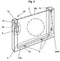
- 3 shows a very simplified perspective view of a second exemplary embodiment.
- the cooling unit of the exemplary embodiment is designed with a cross-flow cooler as the heat exchanger 2 , in which the header boxes 3 , 4 are arranged vertically on the left and right side of the heat exchanger 2 in the installation position shown.
- the collecting boxes 3 , 4 are made of plastic.
- a fan hood 1 also made of plastic, has been arranged in front of the heat exchanger 2 , as seen in the direction of travel (FIG. 2 -X direction) of the motor vehicle.
- the fan cover 1 has a central opening which is surrounded by a frame 31 .
- Carriers 32 run from the frame 31 in a star shape towards the center.
- a fan 30 with a drive unit is mounted in the center in a manner not shown and known per se.
- the fan 30 draws in cooling air through the network of the heat exchanger 2 , which is blown out in the direction of the engine compartment, in order to be used there for further cooling purposes and then to be discharged thereafter.
- the network of the heat exchanger 2 consists of flat tubes 50 with corrugated fins 40 arranged between them, only a few of which have been indicated.
- the cooling unit also includes an oil cooler 60 , which is fastened to the fan cover 1 in a manner not shown here and which is used to cool the transmission oil by means of the circulating coolant of the internal combustion engine, which is also not shown.
- a plurality of fastening means 5a are arranged on the edge 6 thereof, which cooperate with corresponding ones 5b on the header boxes 3 and 4 and on the side parts 25 (top), 26 (bottom) of the heat exchanger 2 . It does not really have to be mentioned that all of the fastening means 5a, 5b formed on the collecting boxes 3, 4 are made of plastic with a certain elasticity. Towards the upper side part 25 there are two fastening means 5 , only one of which can be seen and two fastening means 5 are also provided below.
- fastening means 5a, 5b are provided on the left edge 6 of the fan hood 1 or on the left header box 3 , which will be discussed in more detail below (FIG. 2), and three fastening means 5a, 5b are provided on the opposite side, two of which can be seen.
- Two of these three fastening means 5 consist of a hook-like support 5b, which are formed on the collection box 4 and, wherein the protrusions 5a in the supports 5b engage from pin-like projections 5a which are integrally formed on the edge 6 of the fan hood 1 when preparing the fan hood 1 from above, , 1 shows one of these fastening means 5a, 5b on the right side.
- a further fastening means 5a, 5b is designed as a fixed bearing.
- the fixed bearing is designed so that tolerances between the heat exchanger 2 and the fan cover 1 can be compensated.
- a fastening element 22 is provided through an opening (not shown) in the fastening means on the fan hood side (projection 5a ) and a blind hole (also not shown) in the collecting box 4 .
- the fastening element 22 is located at the upper end of the cooling unit, and consequently at a very easily accessible location, and it can be removed with a single movement in the event of disassembly.
- the already mentioned upper fastening means are hooks which grip over the edge of the upper side part 25 and the lower fastening means 5 are pins on the edge 6 of the fan cover 1 , which are inserted into suitable slots in the lower side part 26 . It should be apparent from FIG. 1 that the upper fastening means 5 are arranged somewhat closer to the collecting box 3 or 4 than the lower fastening means 5 .
- FIG. 2 shows the details of the fastening means 5a , which are important in the present context, on the left edge 6 of the fan hood 1 and on the left collecting box 3 in an enlarged detail, however, the locked position of the latching hook 7 is shown in FIG. 1 and in FIG 2 the situation before insertion or after loosening is shown.
- a projection extends from the edge 6 of the fan hood 1 and is formed in the exemplary embodiment from three reinforced profiles 23 , 24 , 27 .
- the profiles 23 , 24 , 27 converge in a connection point 10 , in which the locking hook 7 is combined with the profiles 23 , 24 , 27 .
- the locking hook 7 has on its front side a locking lug 8 pointing in the X direction and, at approximately the same height, on its rear side an extension 20 pointing in the opposite direction . Further above, an extension 11 has been formed, which is for releasing the locking hook 7 is used. Below the connection point 10 , the locking hook 7 is designed in the manner of a U with two legs 28 , 29 .
- the fastening means 5b on the collecting box 3 consist of a receptacle 9 for the latching hook 7 .
- the receptacle 9 comprises a two-legged support with the cheeks 14 and 15 and with a bottom 13 where the two cheeks 14 , 15 unite.
- a stop 12 formed above the collecting box 3 , on which the catch 8 of the catch hook 7 engages.
- the two legs 28 and 29 of the locking hook 7 include the cheek 14 of the receptacle 9 and the support. In the end position, the latching hook 7 lies on the bottom 13 of the support and the latching lug 8 is latched exactly below the stop 12 . Between the cheeks 14 and 15 , the locking hook 7 has only little play. It can thus be seen that the latching hook 7 forms a fixed bearing in the receptacle 9 , because there is no freedom of movement.
- the above-mentioned extension 20 on the latching hook 7 comes into contact with the cheek 14 from the inside, thereby preventing the fan hood 1 from being released (for example, unintentionally) under the influence of vibrations during operation.
- a pressure force is to be exerted on the extension 11 of the latching hook 7 in the direction of the arrow drawn above the extension 11 , whereupon the latching lug 8 is released and the fan hood 1 can be removed upwards by means of the extension 11 .
- the end of the extension 11 is preferably formed with a recess for manual operation with a finger.
- FIG. 3 shows a basic embodiment with a mounting frame 70 , which can be made of metal or plastic.
- a mounting frame 70 On the mounting frame 70 there are bearings (not shown) with damping elements for supporting the cooling unit in the vehicle.
- the mounting frame 70 has two legs 71 and 72 and a lower cross member 73 connecting the same.
- heat exchangers 2 are inserted and fastened in a manner not shown. Often there are a plurality of heat exchangers 2 arranged one behind the other in the cooling air flow direction in the mounting frame 70 .
- the outline of the heat exchanger 2 was shown by a dotted line.
- the edge 6 of the fan cover 1 and its central opening were drawn by means of a dash-dot line.
- the fan hood 1 gives the mounting frame 70 sufficient rigidity, so that - in contrast to the prior art - an upper cross member between the legs 71 and 72 does not have to be provided.
Landscapes
- Engineering & Computer Science (AREA)
- Mechanical Engineering (AREA)
- General Engineering & Computer Science (AREA)
- Physics & Mathematics (AREA)
- Thermal Sciences (AREA)
- Cooling, Air Intake And Gas Exhaust, And Fuel Tank Arrangements In Propulsion Units (AREA)
Abstract
Description
Ein bekanntes Kühlaggregat der vorstehend beschriebenen Art geht aus der DE 42 44 037 C2 hervor. Bei diesem Kühlaggregat wirken Befestigungsmittel am Rand der Ventilatorhaube mit Befestigungsmittel an den Sammelkästen eines Wärmetauschers zusammen. Obwohl die Montage der Ventilatorhaube bei dem bekannten Kühlaggregat auch dann möglich ist, wenn das Kühlaggregat bereits in einem Kraftfahrzeug eingebaut ist, scheint die Demontage der Ventilatorhaube noch vereinfacht werden zu können, denn um die an beiden Sammelkästen des Wärmetauschers angeformten elastischen Rasthaken zu lösen, das heißt, aus ihrer Arretierstellung befreien zu können, muss ein Werkzeug benutzt werden. Es scheint bei den gewöhnlich vorhandenen Abmessungen des Kühlaggregats auf den ersten Blick für eine einzige Montageperson schwierig zu sein, beide Rasthaken gleichzeitig zu lösen, was aber notwendig ist, um die Ventilatorhaube zu demontieren. Ferner dienen die vorgesehenen Arme, die von der Zarge bis zum Rand der Ventilatorhaube laufen, zwar der Stabilität derselben, jedoch belegen sie einerseits den ohnehin sehr knappen Einbauraum im Fahrzeug und stellen zudem, insbesondere wenn sie nicht sorgfältig entgratet worden sind, ein gewisses Verletzungsrisiko für die Montageperson dar.
In der DE 100 61 561 A1 oder beispielsweise in der WO 99/47875 wurde ein U - förmiger Einbaurahmen vorgesehen. In dem Einbaurahmen befindet sich ein (oder auch mehrere) Wärmetauscher, der darin in geeigneter Weise befestigt ist. An dem Einbaurahmen sind Befestigungsmittel angeordnet, die mit Befestigungsmitteln am Rand der Ventilatorhaube zusammenwirken. Der dort gezeigte Einbaurahmen besitzt eine Quertraverse als Einzelteil, die zwischen den beiden freien Schenkeln des Rahmens anzubringen ist, um dem Einbaurahmen die notwendige Steifigkeit zu geben.
Die erfindungsgemäße Lösung ergibt sich aus den Merkmalen im Kennzeichen des Anspruchs 1.
Weil der elastische Rasthaken am Rand der Ventilatorhaube - nicht am Sammelkasten - ausgebildet ist, der beim Ansetzen der Ventilatorhaube in einer Aufnahme am Sammelkasten oder am Einbaurahmen einrastet, und weil oberhalb der Anschlussstelle des Rasthakens eine Verlängerung ausgebildet ist, wobei durch eine Druckkraft auf die Verlängerung der Rasthaken lösbar und die Ventilatorhaube entfernbar ist, wurde die Montage, aber vor allem die Demontage, der Ventilatorhaube weiter vereinfacht, denn eine einzige Person ist ohne Benutzung eines Werkzeugs in der Lage, den Rasthaken durch Druck auf die Verlängerung zu lösen und die Ventilatorhaube nach oben herauszunehmen.
Der Rasthaken bildet in seiner Einraststellung mit der etwa U - förmigen (zweischenkligen) Aufnahme ein Festlager zwischen Ventilatorhaube und Sammelkasten. Unter anderem dadurch ist es möglich, die Anzahl der Befestigungsmittel insgesamt zu reduzieren.
Der Rasthaken ist formschlüssig in der Aufnahme einrastbar, derart dass in die nach oben und unten weisende Z - Richtung die Rastnase am Anschlag in der Aufnahme (oben) und unten durch die Anlage des Rasthakens auf dem Boden der Aufnahme in der Bewegung begrenzt ist, dass der Rasthaken in Y - Richtung (Querrichtung des Fahrzeugs) einen Schenkel der Aufnahme beidseitig umgreift, und dass der Rasthaken in X - Richtung (Längsrichtung des Fahrzeugs) lediglich geringes Spiel zwischen beiden Schenkeln der Aufnahme aufweist.
Der Rasthaken ist in Verbindung mit der Aufnahme das einzige Befestigungsmittel an einer Seite des Kühlaggregats.
Am Rasthaken ist, etwa auf der Höhe der Rastnase, zu der entgegengesetzten Seite der Rastnase weisend, ein Fortsatz angeformt, der sich zu dem einen Schenkel der Aufnahme erstreckt, um den Rasthaken gegen unbeabsichtigtes Lösen zu sichern. Der Fortsatz wird ferner als Abstützung wirksam und verteilt somit die Aufnahmekräfte, wodurch der Bruch der Aufnahme oder des Rasthakens verhindert wird.
Je zwei weitere Befestigungsmittel sind an den gegenüberliegenden Querseiten (Y-Richtung) des Kühlaggregats angeordnet, die als Stifte und Haken am Rand der Ventilatorhaube ausgebildet sind, die an den Seitenteilen des Wärmetauschers oben und unten zu befestigen sind. Die oberen und unteren Befestigungsmittel sind nicht auf einer gemeinsamen Vertikalen angeordnet. Die oberen Befestigungsmittel befinden sich vorzugsweise näher am linken bzw. rechten Sammelkasten als die unteren Befestigungsmittel. Hier wurde eine deutliche Reduzierung der Anzahl der Befestigungsmittel im Vergleich zum Stand der Technik erreicht.
Die Fig. 1 zeigt eine Perspektivansicht von hinten auf das Kühlaggregat und die Fig. 2 zeigt einen vergrößerten Ausschnitt, und zwar um den Rasthaken herum. Die Fig. 3 zeigt eine sehr vereinfachte perspektivische Ansicht eines zweiten Ausführungsbeispiels.
Die Fig. 3 zeigt ein prinzipielles Ausführungsbeispiel mit einem Einbaurahmen 70, der aus Metall oder aus Kunststoff bestehen kann. An dem Einbaurahmen 70 befinden sich nicht gezeigte Lager mit Dämpfungselementen zur Abstützung des Kühlaggregats im Fahrzeug. Der Einbaurahmen 70 besitzt zwei Schenkel 71 und 72 und eine dieselben verbindende untere Traverse 73. In dem Einbaurahmen 70 sind Wärmetauscher 2 in nicht gezeigter Weise eingesetzt und befestigt. Häufig befinden sich mehrere in Kühlluftströmungsrichtung hintereinander angeordnete Wärmetauscher 2 in dem Einbaurahmen 70. Die Umrandung der Wärmetauscher 2 wurde mittels gepunkteter Linie dargestellt. Der Rand 6 der Ventilatorhaube 1 und ihre zentrische Öffnung wurden mittels Strich - Punkt - Linie gezeichnet. Am linken Schenkel 71 ist eine Aufnahme 9 und ein Anschlag 12 angeordnet, die gemeinsam mit dem in Fig. 2 gezeigten elastischen Rasthaken 7 am Rand 6 der Ventilatorhaube 1 ein Festlager bilden. Ein weiteres Festlager 74 befindet sich auf der gleichen Höhe am rechten Schenkel 72. Ferner sind an der unteren Traverse 73 Befestigungsmittel 5b angeordnet, die mit hier nicht gezeigten Befestigungsmitteln 5a am Rand 6 der Ventilatorhaube 1 zusammenwirken. Die Ventilatorhaube 1 verleiht dem Einbaurahmen 70 eine ausreichende Steifigkeit, so dass - im Unterschied zum Stand der Technik - eine obere Traverse zwischen den Schenkeln 71 und 72 nicht vorgesehen werden muss.
Claims (10)
- Kühlaggregat für Kraftfahrzeuge, mit einer Ventilatorhaube (1) und mit Wärmetauschern, wovon wenigstens ein Wärmetauscher (2) Sammelkästen (3, 4) aufweist, wobei Befestigungsmittel (5a) am Rand (6) der Ventilatorhaube (1) mit Befestigungsmitteln (5b) an den Sammelkästen (3, 4) oder mit Befestigungsmitteln (5b) an einem Einbaurahmen (70) zusammenwirken und wobei wenigstens eines der Befestigungsmittel (5a, 5b) als elastischer Rasthaken (7) mit einer Rastnase (8) und mit einem Anschlag (12) für die Rastnase (8) ausgebildet ist,
dadurch gekennzeichnet, dass
der elastische Rasthaken (7) am Rand (6) der Ventilatorhaube (1) ausgebildet ist, der beim Ansetzen der Ventilatorhaube (1) in einer Aufnahme (9) am Sammelkasten (3) oder am Einbaurahmen (70) einrastet, und dass oberhalb einer Anschlussstelle (10) des Rasthakens (7) eine Verlängerung (11) ausgebildet ist, wobei durch eine Druckkraft auf die Verlängerung (11) der Rasthaken (7) lösbar und die Ventilatorhaube (1) entfernbar ist. - Kühlaggregat nach Anspruch 1, dadurch gekennzeichnet, dass der Rasthaken (7) in seiner Einraststellung in der etwa U - förmigen (zwei Wangen) Aufnahme (9) ein Festlager zwischen Ventilatorhaube (1) und Sammelkasten (3) oder Einbaurahmen (70) darstellt.
- Kühlaggregat nach Anspruch 2 dadurch gekennnzeichnet, dass der Rasthaken (7) formschlüssig in der Aufnahme (9) einrastbar ist, derart dass in die nach oben und unten weisende Z - Richtung die Rastnase (8) an einem Anschlag (12) in der Aufnahme (9, oben) und unten durch die Anlage des Rasthakens (7) auf dem Boden (13) der Aufnahme (9) in der Bewegung begrenzt ist,
dass der Rasthaken (7) in Y - Richtung (Querrichtung des Fahrzeugs) eine Wange (14) der Aufnahme (9) beidseitig umgreift,
und dass der Rasthaken (7) in X - Richtung (Längsrichtung des Fahrzeugs) lediglich geringes Spiel zwischen beiden Wangen (14, 15) der Aufnahme (9) aufweist. - Kühlaggregat nach einem der vorstehenden Ansprüche, dadurch gekennzeichnet, dass der Rasthaken (7) in Verbindung mit der Aufnahme (9) das einzige Befestigungsmittel (5) an einer Seite des Kühlaggregats ist.
- Kühlaggregat nach einem der vorstehenden Ansprüche, dadurch gekennzeichnet, dass am Rasthaken (7), etwa auf der Höhe der Rastnase (8), an der entgegengesetzten Seite der Rastnase (8) ein Fortsatz (20) angeformt ist, der sich zu der einen Wange (14) der Aufnahme (9) erstreckt, um den Rasthaken (7) gegen unbeabsichtigtes Lösen zu sichern.
- Kühlaggregat nach einem der vorstehenden Ansprüche, dadurch gekennzeichnet, dass an der dem Rasthaken (7) gegenüberliegenden Seite des Kühlaggregats zwei oder drei Befestigungsmittel (5) angeordnet sind.
- Kühlaggregat nach einem der vorstehenden Ansprüche, dadurch gekennzeichnet, dass je zwei oder drei weitere Befestigungsmittel (5) an den gegenüberliegenden Querseiten (Y - Richtung) des Kühlaggregats angeordnet sind, die als Stifte und Haken am Rand der Ventilatorhaube ausgebildet sind, die an Seitenteilen (25, 26) des Wärmetauschers (2) zu befestigen sind.
- Kühlaggregat nach einem der vorstehenden Ansprüche, dadurch gekennzeichnet, dass die Anschlussstelle (10) des Rasthakens (7) an einem Profilierungen (23, 24, 27) aufweisenden Vorsprung am Rand (6) der Ventilatorhaube (1) ausgebildet ist.
- Kühlaggregat nach einem der vorstehenden Ansprüche, dadurch gekennzeichnet, dass der Anschlag (12) an der Wand des Sammelkastens (3) oder am Einbaurahmen (70) ausgebildet ist.
- Kühlaggregat nach Anspruch 1, dadurch gekennzeichnet, dass der Einbaurahmen (70) ein nach oben offenes U - Profil ist, dessen zwei Schenkel (71, 72) mittels der Ventilatorhaube (1) an Festlagern (74) zwischen der Ventilatorhaube (1) und den Schenkeln (71) und (72) verbunden sind.
Applications Claiming Priority (2)
| Application Number | Priority Date | Filing Date | Title |
|---|---|---|---|
| DE10307488 | 2003-02-21 | ||
| DE10307488A DE10307488A1 (de) | 2003-02-21 | 2003-02-21 | Kühlaggregat |
Publications (3)
| Publication Number | Publication Date |
|---|---|
| EP1452820A2 true EP1452820A2 (de) | 2004-09-01 |
| EP1452820A3 EP1452820A3 (de) | 2005-11-09 |
| EP1452820B1 EP1452820B1 (de) | 2007-03-07 |
Family
ID=32748021
Family Applications (1)
| Application Number | Title | Priority Date | Filing Date |
|---|---|---|---|
| EP04002114A Expired - Lifetime EP1452820B1 (de) | 2003-02-21 | 2004-01-31 | Kühlaggregat |
Country Status (3)
| Country | Link |
|---|---|
| US (1) | US7007744B2 (de) |
| EP (1) | EP1452820B1 (de) |
| DE (2) | DE10307488A1 (de) |
Cited By (1)
| Publication number | Priority date | Publication date | Assignee | Title |
|---|---|---|---|---|
| EP3739179A1 (de) * | 2019-05-16 | 2020-11-18 | Valeo Autosystemy SP. Z.O.O. | Kühlsystem mit einer ummantelungsanordnung |
Families Citing this family (11)
| Publication number | Priority date | Publication date | Assignee | Title |
|---|---|---|---|---|
| USD532095S1 (en) * | 2004-10-07 | 2006-11-14 | Flex-A-Lite Consolidated, Inc. | Combined fan assembly and shroud |
| JP2007131245A (ja) * | 2005-11-11 | 2007-05-31 | Calsonic Kansei Corp | 車両用エアガイド構造 |
| US7703730B2 (en) * | 2006-10-20 | 2010-04-27 | Denso International America, Inc. | Fastenerless attachment system applied to vehicle engine cooling module components |
| USD565165S1 (en) * | 2006-12-07 | 2008-03-25 | Flex-A-Lite Consolidated, Inc. | Combined dual fan assembly and shroud |
| USD565166S1 (en) * | 2006-12-07 | 2008-03-25 | Flex-A-Lite Consolidated, Inc. | Combined dual fan assembly and shroud with spiderweb support |
| US9618281B2 (en) * | 2010-04-22 | 2017-04-11 | Denso International America, Inc. | Heat exchange device |
| US9091468B2 (en) * | 2011-06-23 | 2015-07-28 | Denso International America, Inc. | Fastener incorporated with nut provision |
| DE102012009950A1 (de) * | 2012-05-18 | 2013-11-21 | Brose Fahrzeugteile GmbH & Co. Kommanditgesellschaft, Würzburg | Kühlerlüftermodul |
| US11326506B2 (en) * | 2019-07-03 | 2022-05-10 | Ford Global Technologies, Llc | Vehicle fan shroud with integrated support structure |
| CA3203590A1 (en) * | 2020-12-03 | 2022-06-09 | Modine Manufacturing Company | Heat exchanger module |
| US12281608B2 (en) * | 2020-12-03 | 2025-04-22 | Modine Manufacturing Company | Heat exchanger module |
Family Cites Families (16)
| Publication number | Priority date | Publication date | Assignee | Title |
|---|---|---|---|---|
| US3947932A (en) * | 1974-04-05 | 1976-04-06 | Gozlan Brothers Limited | Jewellery clasp |
| US4282634A (en) * | 1979-12-21 | 1981-08-11 | Jack Krauss | Buckle |
| DE3536457A1 (de) * | 1985-10-12 | 1987-06-25 | Sueddeutsche Kuehler Behr | Waermetauscher, insbesondere kuehler fuer kraftfahrzeuge |
| US5086547A (en) * | 1990-05-29 | 1992-02-11 | The Napier Company | Box and catch assembly for bracelets, necklaces, etc. |
| JP2548469B2 (ja) * | 1991-09-30 | 1996-10-30 | ワイケイケイ株式会社 | バックル |
| US5219016A (en) * | 1992-06-15 | 1993-06-15 | General Motors Corporation | Radiator, condenser and fan shroud assembly |
| DE4244037C2 (de) * | 1992-12-24 | 1995-10-05 | Behr Gmbh & Co | Kühlaggregat für einen Verbrennungsmotor |
| DE4421835A1 (de) * | 1994-06-22 | 1996-01-04 | Behr Gmbh & Co | Wärmetauscher, insbesondere Kühler für Verbrennungskraftmaschinen von Nutzfahrzeugen |
| DE19526286A1 (de) * | 1995-07-19 | 1997-01-23 | Behr Gmbh & Co | Wärmeübertrager |
| FR2785379B1 (fr) * | 1998-10-29 | 2001-06-15 | Valeo Thermique Moteur Sa | Module d'echange de chaleur comprenant une buse de ventilateur et un echangeur de chaleur, en particulier pour vehicule automobile |
| FR2794170B1 (fr) * | 1999-05-28 | 2001-06-29 | Renault | Dispositif de fixation d'une buse de ventilateur a des elements du groupe refroidisseur d'un moteur a combustion interne de vehicule automobile |
| JP2001124486A (ja) * | 1999-10-25 | 2001-05-11 | Denso Corp | 熱交換器 |
| JP4505955B2 (ja) * | 2000-06-20 | 2010-07-21 | 株式会社デンソー | 送風機の取付構造 |
| JP4201967B2 (ja) * | 2000-09-25 | 2008-12-24 | カルソニックカンセイ株式会社 | 樹脂部材の取付構造 |
| JP4461609B2 (ja) * | 2000-11-10 | 2010-05-12 | トヨタ自動車株式会社 | 電動ファンシュラウドの取付構造 |
| US6615460B1 (en) * | 2002-08-27 | 2003-09-09 | David Baumgarten | Optionally manual or automatic breakaway lanyard buckle |
-
2003
- 2003-02-21 DE DE10307488A patent/DE10307488A1/de not_active Withdrawn
-
2004
- 2004-01-31 DE DE502004003089T patent/DE502004003089D1/de not_active Expired - Lifetime
- 2004-01-31 EP EP04002114A patent/EP1452820B1/de not_active Expired - Lifetime
- 2004-02-23 US US10/784,567 patent/US7007744B2/en not_active Expired - Fee Related
Cited By (1)
| Publication number | Priority date | Publication date | Assignee | Title |
|---|---|---|---|---|
| EP3739179A1 (de) * | 2019-05-16 | 2020-11-18 | Valeo Autosystemy SP. Z.O.O. | Kühlsystem mit einer ummantelungsanordnung |
Also Published As
| Publication number | Publication date |
|---|---|
| US20040250987A1 (en) | 2004-12-16 |
| EP1452820A3 (de) | 2005-11-09 |
| DE10307488A1 (de) | 2004-09-23 |
| DE502004003089D1 (de) | 2007-04-19 |
| EP1452820B1 (de) | 2007-03-07 |
| US7007744B2 (en) | 2006-03-07 |
Similar Documents
| Publication | Publication Date | Title |
|---|---|---|
| EP1415841B1 (de) | Wärmetauscheranordnung | |
| EP0401571B1 (de) | Wärmetauscher zur Kühlung des Kühlwassers und der Ladeluft eines Verbrennungsmotors | |
| DE69916015T2 (de) | Wärmeaustauschmodul mit lüfterhaube und wärmetauscher insbesondere für kraftfahrzeug | |
| EP1452820B1 (de) | Kühlaggregat | |
| DE4421835A1 (de) | Wärmetauscher, insbesondere Kühler für Verbrennungskraftmaschinen von Nutzfahrzeugen | |
| EP1213554A2 (de) | Modulträger für diverse Wärmeübertrager eines Kraftfahrzeugmotors | |
| EP0219021B1 (de) | Wärmetauscher, insbesondere Kühler für Kraftfahrzeuge | |
| DE29707571U1 (de) | Anordnung zur Verbindung von zwei Wärmetauschern | |
| EP1678456B1 (de) | Wärmeübertragermodul für ein kraftfahrzeug | |
| WO2011063916A1 (de) | Axialgebläseanordnung | |
| DE4244037C2 (de) | Kühlaggregat für einen Verbrennungsmotor | |
| DE2103593C2 (de) | Dunstabzugshaube für Küchen | |
| DE602005004498T2 (de) | Kühlungseinrichtung für Kraftfahrzeuge | |
| DE69909739T2 (de) | Vorrichtung zur befestigung einer einrichtung, insbesondere eines wärmetauschers, an einem strukturelement eines kraftfahrzeuges | |
| DE3907926A1 (de) | Waermetauscher, insbesondere kuehler fuer nutzfahrzeuge | |
| DE102007007232A1 (de) | Vorrichtung zur Befestigung eines Zusatzteiles, insbesondere einer Lüfterhaube an einem Wärmeübertrager | |
| DE19605909A1 (de) | Wärmeübertrager | |
| EP0307803A1 (de) | Kraftfahrzeugkühler mit Seitenteilen | |
| DE69800358T2 (de) | Wärmetauscher für Fahrzeuge, mit einem Fixier- und Positionierelement das aus dem Wärmetauscherkern vorspringt | |
| DE102011107211B4 (de) | Trägerrahmen für einen Fahrzeugkühler und Kühlermodul | |
| WO2001046631A1 (de) | Tauwasserauffangschale | |
| DE102005046796A1 (de) | Anordnung zur Befestigung von Wärmeübertragern, insbesondere für ein Kraftfahrzeug | |
| DE19621287B4 (de) | Befestigungsvorrichtung für einen Zusatzwärmeübertrager | |
| DE202004013917U1 (de) | Gargerätemuffel | |
| DE202020107197U1 (de) | Wärmetauscherhalterung mit Schnappverschluss |
Legal Events
| Date | Code | Title | Description |
|---|---|---|---|
| PUAI | Public reference made under article 153(3) epc to a published international application that has entered the european phase |
Free format text: ORIGINAL CODE: 0009012 |
|
| AK | Designated contracting states |
Kind code of ref document: A2 Designated state(s): AT BE BG CH CY CZ DE DK EE ES FI FR GB GR HU IE IT LI LU MC NL PT RO SE SI SK TR |
|
| AX | Request for extension of the european patent |
Extension state: AL LT LV MK |
|
| PUAL | Search report despatched |
Free format text: ORIGINAL CODE: 0009013 |
|
| AK | Designated contracting states |
Kind code of ref document: A3 Designated state(s): AT BE BG CH CY CZ DE DK EE ES FI FR GB GR HU IE IT LI LU MC NL PT RO SE SI SK TR |
|
| AX | Request for extension of the european patent |
Extension state: AL LT LV MK |
|
| 17P | Request for examination filed |
Effective date: 20060509 |
|
| AKX | Designation fees paid |
Designated state(s): DE ES FR GB IT SE |
|
| GRAP | Despatch of communication of intention to grant a patent |
Free format text: ORIGINAL CODE: EPIDOSNIGR1 |
|
| GRAS | Grant fee paid |
Free format text: ORIGINAL CODE: EPIDOSNIGR3 |
|
| GRAA | (expected) grant |
Free format text: ORIGINAL CODE: 0009210 |
|
| AK | Designated contracting states |
Kind code of ref document: B1 Designated state(s): DE ES FR GB IT SE |
|
| REG | Reference to a national code |
Ref country code: GB Ref legal event code: FG4D Free format text: NOT ENGLISH |
|
| REF | Corresponds to: |
Ref document number: 502004003089 Country of ref document: DE Date of ref document: 20070419 Kind code of ref document: P |
|
| PG25 | Lapsed in a contracting state [announced via postgrant information from national office to epo] |
Ref country code: SE Free format text: LAPSE BECAUSE OF FAILURE TO SUBMIT A TRANSLATION OF THE DESCRIPTION OR TO PAY THE FEE WITHIN THE PRESCRIBED TIME-LIMIT Effective date: 20070607 |
|
| PG25 | Lapsed in a contracting state [announced via postgrant information from national office to epo] |
Ref country code: ES Free format text: LAPSE BECAUSE OF FAILURE TO SUBMIT A TRANSLATION OF THE DESCRIPTION OR TO PAY THE FEE WITHIN THE PRESCRIBED TIME-LIMIT Effective date: 20070618 |
|
| GBT | Gb: translation of ep patent filed (gb section 77(6)(a)/1977) |
Effective date: 20070529 |
|
| ET | Fr: translation filed | ||
| PLBE | No opposition filed within time limit |
Free format text: ORIGINAL CODE: 0009261 |
|
| STAA | Information on the status of an ep patent application or granted ep patent |
Free format text: STATUS: NO OPPOSITION FILED WITHIN TIME LIMIT |
|
| 26N | No opposition filed |
Effective date: 20071210 |
|
| PG25 | Lapsed in a contracting state [announced via postgrant information from national office to epo] |
Ref country code: IT Free format text: LAPSE BECAUSE OF FAILURE TO SUBMIT A TRANSLATION OF THE DESCRIPTION OR TO PAY THE FEE WITHIN THE PRESCRIBED TIME-LIMIT Effective date: 20070307 |
|
| REG | Reference to a national code |
Ref country code: FR Ref legal event code: PLFP Year of fee payment: 13 |
|
| REG | Reference to a national code |
Ref country code: FR Ref legal event code: PLFP Year of fee payment: 14 |
|
| REG | Reference to a national code |
Ref country code: FR Ref legal event code: PLFP Year of fee payment: 15 |
|
| PGFP | Annual fee paid to national office [announced via postgrant information from national office to epo] |
Ref country code: PL Payment date: 20190104 Year of fee payment: 8 Ref country code: GB Payment date: 20190128 Year of fee payment: 16 |
|
| GBPC | Gb: european patent ceased through non-payment of renewal fee |
Effective date: 20200131 |
|
| PG25 | Lapsed in a contracting state [announced via postgrant information from national office to epo] |
Ref country code: GB Free format text: LAPSE BECAUSE OF NON-PAYMENT OF DUE FEES Effective date: 20200131 |
|
| PG25 | Lapsed in a contracting state [announced via postgrant information from national office to epo] |
Ref country code: FR Free format text: LAPSE BECAUSE OF NON-PAYMENT OF DUE FEES Effective date: 20200131 |
|
| PGFP | Annual fee paid to national office [announced via postgrant information from national office to epo] |
Ref country code: DE Payment date: 20210629 Year of fee payment: 18 |
|
| REG | Reference to a national code |
Ref country code: DE Ref legal event code: R119 Ref document number: 502004003089 Country of ref document: DE |
|
| PG25 | Lapsed in a contracting state [announced via postgrant information from national office to epo] |
Ref country code: DE Free format text: LAPSE BECAUSE OF NON-PAYMENT OF DUE FEES Effective date: 20220802 |