EP1447221A1 - Flüssigkeitsstrahlkopf - Google Patents
Flüssigkeitsstrahlkopf Download PDFInfo
- Publication number
- EP1447221A1 EP1447221A1 EP02790699A EP02790699A EP1447221A1 EP 1447221 A1 EP1447221 A1 EP 1447221A1 EP 02790699 A EP02790699 A EP 02790699A EP 02790699 A EP02790699 A EP 02790699A EP 1447221 A1 EP1447221 A1 EP 1447221A1
- Authority
- EP
- European Patent Office
- Prior art keywords
- liquid
- ejection
- ejection outlet
- outlet
- restrictor portion
- Prior art date
- Legal status (The legal status is an assumption and is not a legal conclusion. Google has not performed a legal analysis and makes no representation as to the accuracy of the status listed.)
- Granted
Links
Images


Classifications
-
- B—PERFORMING OPERATIONS; TRANSPORTING
- B41—PRINTING; LINING MACHINES; TYPEWRITERS; STAMPS
- B41J—TYPEWRITERS; SELECTIVE PRINTING MECHANISMS, i.e. MECHANISMS PRINTING OTHERWISE THAN FROM A FORME; CORRECTION OF TYPOGRAPHICAL ERRORS
- B41J2/00—Typewriters or selective printing mechanisms characterised by the printing or marking process for which they are designed
- B41J2/005—Typewriters or selective printing mechanisms characterised by the printing or marking process for which they are designed characterised by bringing liquid or particles selectively into contact with a printing material
- B41J2/01—Ink jet
- B41J2/015—Ink jet characterised by the jet generation process
- B41J2/04—Ink jet characterised by the jet generation process generating single droplets or particles on demand
- B41J2/045—Ink jet characterised by the jet generation process generating single droplets or particles on demand by pressure, e.g. electromechanical transducers
- B41J2/05—Ink jet characterised by the jet generation process generating single droplets or particles on demand by pressure, e.g. electromechanical transducers produced by the application of heat
-
- B—PERFORMING OPERATIONS; TRANSPORTING
- B41—PRINTING; LINING MACHINES; TYPEWRITERS; STAMPS
- B41J—TYPEWRITERS; SELECTIVE PRINTING MECHANISMS, i.e. MECHANISMS PRINTING OTHERWISE THAN FROM A FORME; CORRECTION OF TYPOGRAPHICAL ERRORS
- B41J2/00—Typewriters or selective printing mechanisms characterised by the printing or marking process for which they are designed
- B41J2/005—Typewriters or selective printing mechanisms characterised by the printing or marking process for which they are designed characterised by bringing liquid or particles selectively into contact with a printing material
- B41J2/01—Ink jet
- B41J2/135—Nozzles
- B41J2/14—Structure thereof only for on-demand ink jet heads
- B41J2/14016—Structure of bubble jet print heads
- B41J2/14032—Structure of the pressure chamber
- B41J2/1404—Geometrical characteristics
-
- A—HUMAN NECESSITIES
- A61—MEDICAL OR VETERINARY SCIENCE; HYGIENE
- A61M—DEVICES FOR INTRODUCING MEDIA INTO, OR ONTO, THE BODY; DEVICES FOR TRANSDUCING BODY MEDIA OR FOR TAKING MEDIA FROM THE BODY; DEVICES FOR PRODUCING OR ENDING SLEEP OR STUPOR
- A61M15/00—Inhalators
- A61M15/0065—Inhalators with dosage or measuring devices
-
- A—HUMAN NECESSITIES
- A61—MEDICAL OR VETERINARY SCIENCE; HYGIENE
- A61M—DEVICES FOR INTRODUCING MEDIA INTO, OR ONTO, THE BODY; DEVICES FOR TRANSDUCING BODY MEDIA OR FOR TAKING MEDIA FROM THE BODY; DEVICES FOR PRODUCING OR ENDING SLEEP OR STUPOR
- A61M15/00—Inhalators
- A61M15/02—Inhalators with activated or ionised fluids, e.g. electrohydrodynamic [EHD] or electrostatic devices; Ozone-inhalators with radioactive tagged particles
-
- A—HUMAN NECESSITIES
- A61—MEDICAL OR VETERINARY SCIENCE; HYGIENE
- A61M—DEVICES FOR INTRODUCING MEDIA INTO, OR ONTO, THE BODY; DEVICES FOR TRANSDUCING BODY MEDIA OR FOR TAKING MEDIA FROM THE BODY; DEVICES FOR PRODUCING OR ENDING SLEEP OR STUPOR
- A61M15/00—Inhalators
- A61M15/02—Inhalators with activated or ionised fluids, e.g. electrohydrodynamic [EHD] or electrostatic devices; Ozone-inhalators with radioactive tagged particles
- A61M15/025—Bubble jet droplet ejection devices
-
- B—PERFORMING OPERATIONS; TRANSPORTING
- B41—PRINTING; LINING MACHINES; TYPEWRITERS; STAMPS
- B41J—TYPEWRITERS; SELECTIVE PRINTING MECHANISMS, i.e. MECHANISMS PRINTING OTHERWISE THAN FROM A FORME; CORRECTION OF TYPOGRAPHICAL ERRORS
- B41J2/00—Typewriters or selective printing mechanisms characterised by the printing or marking process for which they are designed
- B41J2/005—Typewriters or selective printing mechanisms characterised by the printing or marking process for which they are designed characterised by bringing liquid or particles selectively into contact with a printing material
- B41J2/01—Ink jet
- B41J2/135—Nozzles
- B41J2/14—Structure thereof only for on-demand ink jet heads
- B41J2/14016—Structure of bubble jet print heads
-
- B—PERFORMING OPERATIONS; TRANSPORTING
- B41—PRINTING; LINING MACHINES; TYPEWRITERS; STAMPS
- B41J—TYPEWRITERS; SELECTIVE PRINTING MECHANISMS, i.e. MECHANISMS PRINTING OTHERWISE THAN FROM A FORME; CORRECTION OF TYPOGRAPHICAL ERRORS
- B41J2/00—Typewriters or selective printing mechanisms characterised by the printing or marking process for which they are designed
- B41J2/005—Typewriters or selective printing mechanisms characterised by the printing or marking process for which they are designed characterised by bringing liquid or particles selectively into contact with a printing material
- B41J2/01—Ink jet
- B41J2/135—Nozzles
- B41J2/14—Structure thereof only for on-demand ink jet heads
- B41J2/14016—Structure of bubble jet print heads
- B41J2/14088—Structure of heating means
- B41J2/14112—Resistive element
- B41J2/1412—Shape
-
- B—PERFORMING OPERATIONS; TRANSPORTING
- B41—PRINTING; LINING MACHINES; TYPEWRITERS; STAMPS
- B41J—TYPEWRITERS; SELECTIVE PRINTING MECHANISMS, i.e. MECHANISMS PRINTING OTHERWISE THAN FROM A FORME; CORRECTION OF TYPOGRAPHICAL ERRORS
- B41J2/00—Typewriters or selective printing mechanisms characterised by the printing or marking process for which they are designed
- B41J2/005—Typewriters or selective printing mechanisms characterised by the printing or marking process for which they are designed characterised by bringing liquid or particles selectively into contact with a printing material
- B41J2/01—Ink jet
- B41J2/135—Nozzles
- B41J2/14—Structure thereof only for on-demand ink jet heads
- B41J2/1433—Structure of nozzle plates
-
- B—PERFORMING OPERATIONS; TRANSPORTING
- B41—PRINTING; LINING MACHINES; TYPEWRITERS; STAMPS
- B41J—TYPEWRITERS; SELECTIVE PRINTING MECHANISMS, i.e. MECHANISMS PRINTING OTHERWISE THAN FROM A FORME; CORRECTION OF TYPOGRAPHICAL ERRORS
- B41J2/00—Typewriters or selective printing mechanisms characterised by the printing or marking process for which they are designed
- B41J2/005—Typewriters or selective printing mechanisms characterised by the printing or marking process for which they are designed characterised by bringing liquid or particles selectively into contact with a printing material
- B41J2/01—Ink jet
- B41J2/135—Nozzles
- B41J2/14—Structure thereof only for on-demand ink jet heads
- B41J2002/14387—Front shooter
-
- B—PERFORMING OPERATIONS; TRANSPORTING
- B41—PRINTING; LINING MACHINES; TYPEWRITERS; STAMPS
- B41J—TYPEWRITERS; SELECTIVE PRINTING MECHANISMS, i.e. MECHANISMS PRINTING OTHERWISE THAN FROM A FORME; CORRECTION OF TYPOGRAPHICAL ERRORS
- B41J2/00—Typewriters or selective printing mechanisms characterised by the printing or marking process for which they are designed
- B41J2/005—Typewriters or selective printing mechanisms characterised by the printing or marking process for which they are designed characterised by bringing liquid or particles selectively into contact with a printing material
- B41J2/01—Ink jet
- B41J2/135—Nozzles
- B41J2/14—Structure thereof only for on-demand ink jet heads
- B41J2002/14475—Structure thereof only for on-demand ink jet heads characterised by nozzle shapes or number of orifices per chamber
Definitions
- the present invention relates to a liquid ejection head for ejecting liquid, in the form of a minute liquid droplet.
- a liquid ejection head is preferably employed as an ink jet head in the field of ink jet recording for ejecting recording ink. It is also preferably employed, in the field of medicine, as the liquid ejection head of an inhaling apparatus, or the like, used for atomizing liquid medicine so that the medicine can be inhaled into lungs.
- a liquid ejection head for ejecting liquid in the form of a minute liquid droplet, has been widely employed as an ink jet head in the field of ink jet recording. Not only is an ink jet head required to simply eject liquid droplets, but also it is required to be stable in the direction in which liquid droplets are ejected. Thus, various proposals have been made to meet these requirements.
- Japanese Laid-open Patent Application 5-77422 discloses an ink jet head in which, in order to stabilize ink flight, ejection outlets for ejecting ink are placed in recesses, one for one, being in the center of the bottom of the recess to prevent the body of ink from a given ejection outlet from coming into contact with the body of ink from the ejection outlet adjacent thereto.
- Japanese Laid-open Patent Applications 5-193141 and 11-334069 also disclose an ink jet head in which ejection outlets are placed in recesses, one for one, being in the center of the bottom of the recess.
- the internal surface of the recess is treated to give it a strung affinity for ink, and the outward surface of the member having the ejection outlet member is treated to cause it to repel ink.
- This combination of the structural arrangement and surface treatments is intended to form a meniscus in the recess of the ejection outlet so that ink is ejected with the presence of the meniscus in the recess of the ejection outlet. This, according to the aforementioned applications, improves recording quality by stabilizing liquid ejection.
- the primary object of the present invention is to provide a liquid ejection head which ejects extremely small liquid droplets, more specifically, liquid droplets, the sizes of which are on the order of no more than a pico-liter.
- a liquid ejection head comprising a liquid path; an ejection outlet forming member which constitutes a part of a wall of the liquid and which forms an ejection outlet for ejecting a droplet of liquid; a heat generating element, provided at a position opposing to said ejection outlet of the wall of said liquid flow path, for generating a bubble in the liquid by application of heat to the liquid; a restrictor portion, provided at a recessed portion of said ejection outlet, wherein said recessed portion is recessed from a plane in which said ejection outlet is formed, wherein the liquid forms a meniscus and is retained in said ejection outlet such that said restrictor portion is within the liquid, wherein an area So of an opening of said restrictor portion and a surface Sh of said heat generating element satisfy So ⁇ Sh.
- a liquid ejection head comprising a liquid path; an ejection outlet forming member which constitutes a part of a wall of the liquid and which forms an ejection outlet for ejecting a droplet of liquid; an energy generating element, provided at a position opposing to said ejection outlet of the wall of said liquid flow path, for generating ejection energy to be applied to the liquid; a restrictor portion, provided at a recessed portion of said ejection outlet, wherein said recessed portion is recessed from a plane in which said ejection outlet is formed, wherein the liquid forms a meniscus and is retained in said ejection outlet such that said restrictor portion is within the liquid, wherein a thickness e of said restrictor portion and a height e of said liquid path measured in a direction in which said ejection outlet and said energy generating element are faced to each other, satisfy c ⁇ e.
- a liquid ejection head comprises a liquid path; an ejection outlet forming member which constitutes a part of a wall of the liquid and which forms an ejection outlet for ejecting a droplet of liquid; an energy generating element, provided at a position opposing to said ejection outlet of the wall of said liquid flow path, for generating ejection energy to be applied to the liquid; a restrictor portion, provided at a recessed portion of said ejection outlet, wherein said recessed portion is recessed from a plane in which said ejection outlet is formed, wherein the liquid forms a meniscus and is retained in said ejection outlet such that said restrictor portion is within the liquid, wherein a thickness c of said restrictor portion and a thickness d of said ejection outlet forming member measured between a plane in which said ejection outlet is formed and said restrictor portion, satisfy c ⁇ d.
- the position of the restrictor portion in the ejection outlet, in terms of the thickness direction of the member having the energy generating members, is desired to be between the Lop and bottom surfaces of the member.
- the hole of the restrictor portion is tapered so that the top opening of the hole is greater than that of the bottom opening of the hole, or vice versa, Further, the restrictor portion is desired to have a plurality of holes, as liquid passages, smaller than the other portions of the ejection outlet.
- liquid ejectable from a liquid ejection head there are recording liquids used for ink jet recording, liquid medicines inhaled into lungs, etc.
- a liquid ejection head such as the above described one, prior to the beginning of ejection, the outward opening of each ejection outlet of the member having the ejection outlets is covered with the meniscus formed by the liquid in the head, with the small hole of the restrictor portion being in the liquid in the head. Then, as the heat generating element is driven to eject liquid, a bubble is generated, and the bubble grows while moving the liquid toward at least, the outward opening of the ejection outlet. As the liquid is moved toward the outward opening of the ejection outlet, it is forced through the small hole of the restrictor portion, being thereby substantially increased in speed as it is moved through the small hole.
- the speed at which the liquid moves after being moved through the small hole of the restrictor portion is much faster than prior to its passage through the small hole.
- the portion of the ink in the recess of the ejection outlet, which corresponds in position to the small hole of the restrictor portion is moved faster than the body of ink surrounding Lhis portion of ink.
- this fast moving portion of liquid causes the center portion, that is, the portion corresponding in position to the small bole of the restrictor portion, of the meniscus covering the outward opening of the ejection ouLleL. Lo swell up, and eventually, it ejects in the form of a liquid droplet.
- the entirety of the body of ink in the recess, or the large diameter portion, of the ejection outlet is not ejected. Therefore, the liquid ejection head in accordance with the present invention can eject liquid droplets, which are much smaller in size compared to those ejected by a liquid ejection head in accordance with the prior arts.
- Figure 1 shows the liquid ejection head in an embodiment of the present invention.
- Figure 1(a) being a plan view thereof
- Figure 1(b) being a sectional view thereof, at the plane X-X in Figure 1(a).
- the liquid ejection head shown in Figure 1. comprises a substrate 2, and a heater 1, as an element for generating the energy for liquid ejection.
- the heater 1 is disposed in the liquid path.
- Figure 1 shows the combination of one heater 1 and one liquid path 3, there are disposed a plurality of the heaters 1, one for each liquid path 3, on a single piece of substrate 2.
- the choice of the energy generating element does not need to be limited to an electrothermal transducing element.
- it may be a vibratory energy generating element such as a piezoelectric element.
- Each liquid path 3 is surrounded by an ejection outlet plate 5 having the ejection outlets 4 through which liquid is ejected in the form of a liquid droplet, the substrate 2, and a gap regulating member 6 for regulating the distance between the ejection outlet plate 5 and substrate 2.
- the ejection outlet is provided with a restrictor portion 7, at which the ejection outlet diameter is substantially smaller than at Lhe other portions, at a position recessed from an ejection outlet plane 5b where the ejection outlet 4 opens in the ejection plate 5.
- the liquid to be ejected is held in the recess formed by the internal surface 5a of the larger diameter portion of the ejection outlet and the restrictor portion 7, forming a meniscus 8 across the outward opening of the ejection outlet. Therefore, the restrictor portion 7 is in the liquid between the liquid path 3 and the ejection outlet plate 5a of the ejection outlet plate 5.
- the heater 1 is square, and each edge is 10 pm long.
- its diameter is 10 ⁇ m at the ejection outlet plane 5a (diameter a ), and 3 ⁇ m at the bottom opening; in other words, the diameter b of the small hole 7a of the restrictor portion 7 is 3 ⁇ m.
- the thickness c of the restrictor portion 7 is 1 pm.
- the distance d from the top surface of the restrictor portion 7 to the ejection outlet plane 5a of the ejection outlet plate 5 is 4 ⁇ m, and the height e of the liquid paLh 3 (height of distance regulating member) is 5 ⁇ m.
- the thickness f of the ejection outlet plate 5 is 5 pm.
- the area size So of the small hole 7a and the surface area size Sh of the heater 1 satisfy the following relationship: So ⁇ Sh.
- So ⁇ Sh 100 ⁇ m 2
- So 7.07 ⁇ m 2
- the thickness c of the restrictor portion 7 and the height e of the liquid path 3 satisfy the following relationship: c ⁇ e.
- c 1 ⁇ m
- e 5 ⁇ m
- the thickness c of the restrictor portion 7 and the distance d from the top surface of the restrictor portion 7 to the ejection outlet plane of the ejection outlet plate 5 satisfy the following relationship; c ⁇ d.
- c 1 ⁇ m
- d 4 ⁇ m, as mentioned above, satisfying therefore: c ⁇ d.
- Figure 2 shows how liquid is ejected as the head structured as shown in Figure 1 is driven.
- the small hole 7a remains within the liquid, being thereby prevented from suffering from the problem that it becomes plugged as the liquid therein dries up.
- the liquid ejection head structured as described above can eject desirable liquid droplets from the very beginning of a liquid ejecting operation.
- Figure 3 shows the first modified version of the liquid ejection head shown in Figure 1.
- This modification is different from the liquid ejection head shown in Figure 1 in that the small hole 7a of the restrictor portion 7 is tapered so that it is greater in diameter on the liquid path side, or the inward side, than on the ejection outlet plane 5q side. Even if the small hole 7a of the restrictor portion 7 is tapered as described above, the effect similar to that of the liquid ejection head shown in Figure 1 can be obtained, as long as the above described relationships, that is, So ⁇ Sh, c ⁇ e, and/or c ⁇ d, are satisfied.
- Figure 3 shows a small hole 7a, the diameter of which gradually reduces from the liquid path 3 side toward the ejection outlet plane 5a.
- the taper of the small hole 7a may be such that the diameter of the small hole 7a gradually reduces from the ejection outlet plane 5a toward the liquid path 3 side, or that the diameter of the small hole 7a gradually reduces from the liquid path 3 side toward a given point between the liquid path 3 and the ejection outlet plane 5a, and then, gradually increases from this point toward the ejection outlet plane 5a.
- the edges of the small hole 7a of the restrictor portion 7 may be rounded. In other words, as long as the small hole 7a of the restrictor portion 7 is tapered so that its diameter gradually reduces or increases toward the liquid path or recess, its configuration is optional.
- Figure 4 shows the second modification of the liquid ejection head shown in Figure 1.
- the liquid ejection head shown in Figure 4 is different from the liquid ejection head shown in Figure 1 in that the restrictor portion 7 is positioned between the outward edge of the ejection outlet 4 of the ejection outlet plate 5 and the top surface of the regulating member 6 for defining the height of the liquid path 3.
- the effect similar to that realized by the liquid ejection outlet shown in Figure 1 can be realized as long as the above described relationships: So ⁇ Sh, c ⁇ e, and/or c ⁇ d, are satisfied.
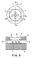
- Figure 5 shows the third modification of the liquid ejection head shown in Figure 1.
- the restrictor portion 7 is provided with a plurality of small holes 7a, which oppose a single heater 1.
- a liquid ejection head in accordance with the present invention ejects (inclusive of atomizing) liquid in the form of an remarkably small droplet, being therefore highly recommendable as the liquid ejection head for such an apparatus as an ink jet recording head in the field of ink jet recording and a liquid medicine inhaler head in the field of medicine.
- a liquid ejection in accordance with the present invention When a liquid ejection in accordance with the present invention is employed as an ink jet recording head, its ejection outlets are disposed in a single or plurality of straight lines, and as for the liquid to be ejected, recording liquid such as ink, or surface treatment liquid adhered to a recording sheet, prior to ink ejection, to prevent ink from bleeding through the recording sheet, are used.
- the direction in which ejection outlets are aligned and/or the length of the line in which the ejection outlets are aligned may be varied as necessary to create an ink jet recording head for a serial type ink jet recording apparatus, or an ink jet recording head for a line type ink jet recording apparatus.
- the liquid ejection head, and the container in which the recording liquid to be supplied to the liquid ejection head is held may be structured in the form of a cartridge so that they can be united or separated.
- a liquid ejection head in accordance with the present invention can be used for ejecting recording ink in the field of ink jet recording.
- a liquid ejection head in accordance with the present invention can also be used as a head for a liquid medicine inhaling apparatus.
- the liquid ejection head is structured so that it can be connected to a liquid medicine dispenser.
- the medicine to be ejected there are: proteinaceous formulations, such as insulin, human growth hormone, and gonadotropic hormone; nicotine; anesthetic; etc.
Landscapes
- Health & Medical Sciences (AREA)
- Engineering & Computer Science (AREA)
- Life Sciences & Earth Sciences (AREA)
- Animal Behavior & Ethology (AREA)
- Public Health (AREA)
- Pulmonology (AREA)
- Anesthesiology (AREA)
- Biomedical Technology (AREA)
- Heart & Thoracic Surgery (AREA)
- Hematology (AREA)
- Veterinary Medicine (AREA)
- General Health & Medical Sciences (AREA)
- Bioinformatics & Cheminformatics (AREA)
- Biophysics (AREA)
- Physics & Mathematics (AREA)
- Geometry (AREA)
- Particle Formation And Scattering Control In Inkjet Printers (AREA)
- Nozzles (AREA)
- Percussion Or Vibration Massage (AREA)
- Surgical Instruments (AREA)
Applications Claiming Priority (7)
| Application Number | Priority Date | Filing Date | Title |
|---|---|---|---|
| JP2001358292A JP2003154665A (ja) | 2001-11-22 | 2001-11-22 | 液体吐出ヘッド |
| JP2001358291 | 2001-11-22 | ||
| JP2001358293 | 2001-11-22 | ||
| JP2001358293A JP2003154655A (ja) | 2001-11-22 | 2001-11-22 | 液体吐出ヘッド |
| JP2001358291A JP2003154664A (ja) | 2001-11-22 | 2001-11-22 | 液体吐出ヘッド |
| JP2001358292 | 2001-11-22 | ||
| PCT/JP2002/012235 WO2003043826A1 (en) | 2001-11-22 | 2002-11-22 | Liquid jet head |
Publications (3)
| Publication Number | Publication Date |
|---|---|
| EP1447221A1 true EP1447221A1 (de) | 2004-08-18 |
| EP1447221A4 EP1447221A4 (de) | 2005-06-15 |
| EP1447221B1 EP1447221B1 (de) | 2009-11-11 |
Family
ID=27347865
Family Applications (1)
| Application Number | Title | Priority Date | Filing Date |
|---|---|---|---|
| EP02790699A Expired - Lifetime EP1447221B1 (de) | 2001-11-22 | 2002-11-22 | Flüssigkeitsstrahlkopf |
Country Status (8)
| Country | Link |
|---|---|
| US (1) | US6926392B2 (de) |
| EP (1) | EP1447221B1 (de) |
| KR (2) | KR20060028658A (de) |
| CN (1) | CN100339219C (de) |
| AT (1) | ATE448085T1 (de) |
| CA (1) | CA2436011C (de) |
| DE (1) | DE60234373D1 (de) |
| WO (1) | WO2003043826A1 (de) |
Cited By (3)
| Publication number | Priority date | Publication date | Assignee | Title |
|---|---|---|---|---|
| EP1706271A4 (de) * | 2003-12-30 | 2009-08-19 | Dimatix Inc | Tropfenausstossanordnung |
| EP3300892A1 (de) * | 2016-09-29 | 2018-04-04 | SII Printek Inc | Ausstosslochplatte, flüssigkeitsausstosskopf und flüssigkeitsausstossvorrichtung |
| CN109641454A (zh) * | 2016-10-14 | 2019-04-16 | 惠普发展公司,有限责任合伙企业 | 流体喷射装置 |
Families Citing this family (18)
| Publication number | Priority date | Publication date | Assignee | Title |
|---|---|---|---|---|
| JP4147234B2 (ja) * | 2004-09-27 | 2008-09-10 | キヤノン株式会社 | 吐出用液体、吐出方法、カートリッジ及び吐出装置 |
| JPWO2005037557A1 (ja) | 2003-10-22 | 2006-12-28 | キヤノン株式会社 | 液体吐出ヘッド |
| JP4147235B2 (ja) * | 2004-09-27 | 2008-09-10 | キヤノン株式会社 | 吐出用液体、吐出方法、液滴化方法、液体吐出カートリッジ及び吐出装置 |
| JP2006087815A (ja) * | 2004-09-27 | 2006-04-06 | Canon Inc | 噴霧方法および該方法に基づく噴霧装置 |
| JP4632421B2 (ja) * | 2004-12-07 | 2011-02-16 | キヤノン株式会社 | インクジェット記録ヘッド |
| JP2006212203A (ja) * | 2005-02-03 | 2006-08-17 | Canon Inc | 吸入装置、及び液剤吐出カートリッジ |
| JP4646669B2 (ja) * | 2005-03-30 | 2011-03-09 | キヤノン株式会社 | 吐出用液体、吐出方法、液滴化方法、カートリッジ及び吐出装置 |
| JP4689340B2 (ja) * | 2005-05-02 | 2011-05-25 | キヤノン株式会社 | 吐出用液体医薬組成物 |
| JP4777225B2 (ja) * | 2006-12-04 | 2011-09-21 | キヤノン株式会社 | 吐出用液体及び吐出方法 |
| JP4428391B2 (ja) * | 2007-03-14 | 2010-03-10 | セイコーエプソン株式会社 | 流体噴射ヘッド及び流体噴射装置 |
| US7746769B2 (en) * | 2007-03-26 | 2010-06-29 | Alcatel Lucent | Management of redundant and multi-segment pseudo-wire |
| JP5424556B2 (ja) * | 2007-12-07 | 2014-02-26 | キヤノン株式会社 | 回転対称性を有しない吐出口を有する液体吐出ヘッド |
| JP2009286047A (ja) * | 2008-05-30 | 2009-12-10 | Canon Inc | 液体吐出方法および液体吐出装置 |
| JP2010207297A (ja) * | 2009-03-09 | 2010-09-24 | Canon Inc | 液体吐出装置及び液体吐出方法 |
| JP2010246669A (ja) * | 2009-04-14 | 2010-11-04 | Canon Inc | 吸入装置用の液体吐出ヘッドおよび吸入装置 |
| US9889651B2 (en) | 2015-03-30 | 2018-02-13 | Funai Electric Co., Ltd. | Fluid ejection device for depositing a discrete quantity of fluid onto a surface |
| US9586399B2 (en) | 2015-03-30 | 2017-03-07 | Funai Electric Co., Ltd. | Fluid ejection device for depositing a discrete quantity of fluid onto a surface |
| JP2018199235A (ja) * | 2017-05-26 | 2018-12-20 | キヤノン株式会社 | 液体吐出ヘッド |
Family Cites Families (24)
| Publication number | Priority date | Publication date | Assignee | Title |
|---|---|---|---|---|
| JPS6137429A (ja) * | 1984-07-31 | 1986-02-22 | Dainippon Ink & Chem Inc | 表裏両面印刷機 |
| JPH064320B2 (ja) * | 1984-07-31 | 1994-01-19 | キヤノン株式会社 | インクジエツト記録ヘツド |
| JPS61262131A (ja) * | 1985-05-16 | 1986-11-20 | Olympus Optical Co Ltd | インクジエツトプリンタにおける画像濃度調整記録方法 |
| JP2666255B2 (ja) * | 1986-07-11 | 1997-10-22 | セイコーエプソン株式会社 | インクジエツト記録装置 |
| JP2658204B2 (ja) * | 1988-06-30 | 1997-09-30 | 富士ゼロックス株式会社 | インクジェット記録装置 |
| JP3179834B2 (ja) | 1991-07-19 | 2001-06-25 | 株式会社リコー | 液体飛翔記録装置 |
| JPH05193141A (ja) | 1992-01-20 | 1993-08-03 | Seiko Epson Corp | インクジェットヘッド |
| JPH06143567A (ja) * | 1992-11-09 | 1994-05-24 | Seiko Epson Corp | インクジェットヘッド |
| MX9601557A (es) * | 1995-04-26 | 1997-06-28 | Canon Kk | Cabeza de eyeccion de liquido, dispositivo de eyeccion de liquido y metodo de eyeccion de liquido. |
| US5821962A (en) * | 1995-06-02 | 1998-10-13 | Canon Kabushiki Kaisha | Liquid ejection apparatus and method |
| JP3403008B2 (ja) | 1996-07-05 | 2003-05-06 | キヤノン株式会社 | 液体吐出ヘッドおよびそれを用いたヘッドカートリッジと記録装置 |
| JP3403009B2 (ja) | 1996-07-12 | 2003-05-06 | キヤノン株式会社 | 可動部材の変位と気泡成長を伴う液体吐出方法、該吐出方法に用いられる液体吐出ヘッド、ヘッドカートリッジ及びこれらを用いた液体吐出装置 |
| JP3372827B2 (ja) * | 1996-07-12 | 2003-02-04 | キヤノン株式会社 | 液体吐出方法及び液体吐出ヘッド並びに該吐出ヘッドを用いたヘッドカートリッジ及び液体吐出装置 |
| EP0822080B8 (de) | 1996-07-31 | 2003-12-03 | Canon Kabushiki Kaisha | Mit Bläschen angetriebener Druckkopf und Vorrichtung welche denselben verwendet |
| US6350016B1 (en) | 1998-02-10 | 2002-02-26 | Canon Kabushiki Kaisha | Liquid ejecting method and liquid ejecting head |
| JPH11334069A (ja) | 1998-05-27 | 1999-12-07 | Oki Data Corp | インクジェットヘッド |
| AU766832B2 (en) | 1998-07-28 | 2003-10-23 | Canon Kabushiki Kaisha | Liquid discharging head and liquid discharging method |
| CA2278982C (en) | 1998-07-28 | 2008-03-25 | Canon Kabushiki Kaisha | Liquid discharge head, liquid discharge method, and liquid discharge apparatus |
| US6409317B1 (en) | 1998-08-21 | 2002-06-25 | Canon Kabushiki Kaisha | Liquid discharge head, liquid discharge method and liquid discharge apparatus |
| US6313435B1 (en) * | 1998-11-20 | 2001-11-06 | 3M Innovative Properties Company | Mask orbiting for laser ablated feature formation |
| DE69940298D1 (de) * | 1998-12-29 | 2009-03-05 | Canon Kk | Flüssigkeitsausstosskopf, Flüssigkeitsausstossverfahren und Flüssigkeitsausstossdruckgerät |
| JP3797648B2 (ja) | 1999-07-27 | 2006-07-19 | キヤノン株式会社 | 液体吐出ヘッド及び該液体吐出ヘッドを用いた記録装置 |
| JP2002210965A (ja) * | 2001-01-17 | 2002-07-31 | Seiko Epson Corp | ノズルプレート及びインクジェット式記録ヘッド並びにインクジェット式記録装置 |
| JP2002321364A (ja) * | 2001-04-25 | 2002-11-05 | Fuji Photo Film Co Ltd | インクジェット記録ヘッドおよびインクジェットプリンタ |
-
2002
- 2002-11-22 KR KR1020067003834A patent/KR20060028658A/ko not_active Ceased
- 2002-11-22 DE DE60234373T patent/DE60234373D1/de not_active Expired - Lifetime
- 2002-11-22 CN CNB028050363A patent/CN100339219C/zh not_active Expired - Fee Related
- 2002-11-22 AT AT02790699T patent/ATE448085T1/de not_active IP Right Cessation
- 2002-11-22 WO PCT/JP2002/012235 patent/WO2003043826A1/ja not_active Ceased
- 2002-11-22 KR KR10-2003-7009670A patent/KR20040020879A/ko not_active Ceased
- 2002-11-22 CA CA002436011A patent/CA2436011C/en not_active Expired - Fee Related
- 2002-11-22 EP EP02790699A patent/EP1447221B1/de not_active Expired - Lifetime
-
2003
- 2003-07-17 US US10/620,421 patent/US6926392B2/en not_active Expired - Fee Related
Cited By (7)
| Publication number | Priority date | Publication date | Assignee | Title |
|---|---|---|---|---|
| EP1706271A4 (de) * | 2003-12-30 | 2009-08-19 | Dimatix Inc | Tropfenausstossanordnung |
| EP3300892A1 (de) * | 2016-09-29 | 2018-04-04 | SII Printek Inc | Ausstosslochplatte, flüssigkeitsausstosskopf und flüssigkeitsausstossvorrichtung |
| US10131145B2 (en) | 2016-09-29 | 2018-11-20 | Sii Printek Inc. | Ejection hole plate, liquid ejection head, and liquid ejection apparatus |
| CN109641454A (zh) * | 2016-10-14 | 2019-04-16 | 惠普发展公司,有限责任合伙企业 | 流体喷射装置 |
| EP3468801A4 (de) * | 2016-10-14 | 2020-02-26 | Hewlett-Packard Development Company, L.P. | Flüssigkeitsausstossvorrichtung |
| US10632747B2 (en) | 2016-10-14 | 2020-04-28 | Hewlett-Packard Development Company, L.P. | Fluid ejection device |
| CN109641454B (zh) * | 2016-10-14 | 2021-12-28 | 惠普发展公司,有限责任合伙企业 | 流体喷射装置 |
Also Published As
| Publication number | Publication date |
|---|---|
| EP1447221B1 (de) | 2009-11-11 |
| CN100339219C (zh) | 2007-09-26 |
| KR20060028658A (ko) | 2006-03-30 |
| US20050073556A1 (en) | 2005-04-07 |
| CA2436011C (en) | 2009-03-10 |
| WO2003043826A1 (en) | 2003-05-30 |
| KR20040020879A (ko) | 2004-03-09 |
| CN1491162A (zh) | 2004-04-21 |
| CA2436011A1 (en) | 2003-05-30 |
| DE60234373D1 (de) | 2009-12-24 |
| US6926392B2 (en) | 2005-08-09 |
| ATE448085T1 (de) | 2009-11-15 |
| EP1447221A4 (de) | 2005-06-15 |
Similar Documents
| Publication | Publication Date | Title |
|---|---|---|
| US6926392B2 (en) | Liquid ejection head | |
| US8020973B2 (en) | Method of manufacturing a liquid droplet spray device and such spray device | |
| EP0770487B1 (de) | Nicht kreisförmige Druckkopföffnung | |
| CN1191807A (zh) | 雾滴减少的喷墨式打印头喷孔 | |
| US6224197B1 (en) | Liquid jet recording head having tapered liquid passages | |
| US8342170B2 (en) | Liquid ejection method and liquid ejection apparatus | |
| CN100358723C (zh) | 微滴喷射器 | |
| EP1273355B1 (de) | Verfahren zur Herstellung eines Tröpfchen-Verneblers und ein solcher Vernebler | |
| JP5424556B2 (ja) | 回転対称性を有しない吐出口を有する液体吐出ヘッド | |
| JP2003154655A (ja) | 液体吐出ヘッド | |
| JP2003154665A (ja) | 液体吐出ヘッド | |
| EP4039297A1 (de) | Arzneimittelabgabevorrichtung, verfahren zur steuerung der flüssigkeitsfahne und verfahren zur injektion der nasenhöhle | |
| WO2005037557A1 (ja) | 液体吐出ヘッド | |
| JP2006116972A (ja) | 肺吸入用の液状薬剤を噴霧するヘッド及びこれを備えた噴霧装置、並びに、その液状薬剤の噴霧方法 | |
| JPH06340073A (ja) | インクジェットヘッド | |
| JP2003154664A (ja) | 液体吐出ヘッド | |
| JP2008055916A (ja) | 液体吐出ヘッド | |
| EP4039299A1 (de) | Arzneimittelabgabevorrichtung, verfahren zur steuerung der flüssigkeitsfahne und verfahren zur injektion der nasenhöhle | |
| JP2007326310A (ja) | 液体吐出ヘッドおよび液体吐出方法 | |
| JPH1158726A (ja) | インクジェットヘッド |
Legal Events
| Date | Code | Title | Description |
|---|---|---|---|
| PUAI | Public reference made under article 153(3) epc to a published international application that has entered the european phase |
Free format text: ORIGINAL CODE: 0009012 |
|
| 17P | Request for examination filed |
Effective date: 20030721 |
|
| AK | Designated contracting states |
Kind code of ref document: A1 Designated state(s): AT BE BG CH CY CZ DE DK EE ES FI FR GB GR IE IT LI LU MC NL PT SE SK TR |
|
| A4 | Supplementary search report drawn up and despatched |
Effective date: 20050504 |
|
| RIC1 | Information provided on ipc code assigned before grant |
Ipc: 7B 05B 1/24 B Ipc: 7A 61M 15/00 B Ipc: 7B 41J 2/14 A |
|
| 17Q | First examination report despatched |
Effective date: 20050929 |
|
| 17Q | First examination report despatched |
Effective date: 20050929 |
|
| GRAP | Despatch of communication of intention to grant a patent |
Free format text: ORIGINAL CODE: EPIDOSNIGR1 |
|
| GRAS | Grant fee paid |
Free format text: ORIGINAL CODE: EPIDOSNIGR3 |
|
| GRAA | (expected) grant |
Free format text: ORIGINAL CODE: 0009210 |
|
| AK | Designated contracting states |
Kind code of ref document: B1 Designated state(s): AT BE BG CH CY CZ DE DK EE ES FI FR GB GR IE IT LI LU MC NL PT SE SK TR |
|
| REG | Reference to a national code |
Ref country code: GB Ref legal event code: FG4D |
|
| REG | Reference to a national code |
Ref country code: CH Ref legal event code: EP |
|
| REG | Reference to a national code |
Ref country code: IE Ref legal event code: FG4D |
|
| REF | Corresponds to: |
Ref document number: 60234373 Country of ref document: DE Date of ref document: 20091224 Kind code of ref document: P |
|
| NLV1 | Nl: lapsed or annulled due to failure to fulfill the requirements of art. 29p and 29m of the patents act | ||
| PG25 | Lapsed in a contracting state [announced via postgrant information from national office to epo] |
Ref country code: SE Free format text: LAPSE BECAUSE OF FAILURE TO SUBMIT A TRANSLATION OF THE DESCRIPTION OR TO PAY THE FEE WITHIN THE PRESCRIBED TIME-LIMIT Effective date: 20091111 Ref country code: FI Free format text: LAPSE BECAUSE OF FAILURE TO SUBMIT A TRANSLATION OF THE DESCRIPTION OR TO PAY THE FEE WITHIN THE PRESCRIBED TIME-LIMIT Effective date: 20091111 Ref country code: PT Free format text: LAPSE BECAUSE OF FAILURE TO SUBMIT A TRANSLATION OF THE DESCRIPTION OR TO PAY THE FEE WITHIN THE PRESCRIBED TIME-LIMIT Effective date: 20100311 Ref country code: ES Free format text: LAPSE BECAUSE OF FAILURE TO SUBMIT A TRANSLATION OF THE DESCRIPTION OR TO PAY THE FEE WITHIN THE PRESCRIBED TIME-LIMIT Effective date: 20100222 |
|
| PG25 | Lapsed in a contracting state [announced via postgrant information from national office to epo] |
Ref country code: CY Free format text: LAPSE BECAUSE OF FAILURE TO SUBMIT A TRANSLATION OF THE DESCRIPTION OR TO PAY THE FEE WITHIN THE PRESCRIBED TIME-LIMIT Effective date: 20091111 |
|
| PG25 | Lapsed in a contracting state [announced via postgrant information from national office to epo] |
Ref country code: AT Free format text: LAPSE BECAUSE OF FAILURE TO SUBMIT A TRANSLATION OF THE DESCRIPTION OR TO PAY THE FEE WITHIN THE PRESCRIBED TIME-LIMIT Effective date: 20091111 Ref country code: BE Free format text: LAPSE BECAUSE OF FAILURE TO SUBMIT A TRANSLATION OF THE DESCRIPTION OR TO PAY THE FEE WITHIN THE PRESCRIBED TIME-LIMIT Effective date: 20091111 Ref country code: MC Free format text: LAPSE BECAUSE OF NON-PAYMENT OF DUE FEES Effective date: 20091130 |
|
| REG | Reference to a national code |
Ref country code: CH Ref legal event code: PL |
|
| PG25 | Lapsed in a contracting state [announced via postgrant information from national office to epo] |
Ref country code: EE Free format text: LAPSE BECAUSE OF FAILURE TO SUBMIT A TRANSLATION OF THE DESCRIPTION OR TO PAY THE FEE WITHIN THE PRESCRIBED TIME-LIMIT Effective date: 20091111 Ref country code: DK Free format text: LAPSE BECAUSE OF FAILURE TO SUBMIT A TRANSLATION OF THE DESCRIPTION OR TO PAY THE FEE WITHIN THE PRESCRIBED TIME-LIMIT Effective date: 20091111 Ref country code: BG Free format text: LAPSE BECAUSE OF FAILURE TO SUBMIT A TRANSLATION OF THE DESCRIPTION OR TO PAY THE FEE WITHIN THE PRESCRIBED TIME-LIMIT Effective date: 20100211 |
|
| PG25 | Lapsed in a contracting state [announced via postgrant information from national office to epo] |
Ref country code: CZ Free format text: LAPSE BECAUSE OF FAILURE TO SUBMIT A TRANSLATION OF THE DESCRIPTION OR TO PAY THE FEE WITHIN THE PRESCRIBED TIME-LIMIT Effective date: 20091111 Ref country code: SK Free format text: LAPSE BECAUSE OF FAILURE TO SUBMIT A TRANSLATION OF THE DESCRIPTION OR TO PAY THE FEE WITHIN THE PRESCRIBED TIME-LIMIT Effective date: 20091111 |
|
| PLBE | No opposition filed within time limit |
Free format text: ORIGINAL CODE: 0009261 |
|
| STAA | Information on the status of an ep patent application or granted ep patent |
Free format text: STATUS: NO OPPOSITION FILED WITHIN TIME LIMIT |
|
| 26N | No opposition filed |
Effective date: 20100812 |
|
| PG25 | Lapsed in a contracting state [announced via postgrant information from national office to epo] |
Ref country code: IE Free format text: LAPSE BECAUSE OF NON-PAYMENT OF DUE FEES Effective date: 20091122 Ref country code: CH Free format text: LAPSE BECAUSE OF NON-PAYMENT OF DUE FEES Effective date: 20091130 Ref country code: GR Free format text: LAPSE BECAUSE OF FAILURE TO SUBMIT A TRANSLATION OF THE DESCRIPTION OR TO PAY THE FEE WITHIN THE PRESCRIBED TIME-LIMIT Effective date: 20100212 Ref country code: LI Free format text: LAPSE BECAUSE OF NON-PAYMENT OF DUE FEES Effective date: 20091130 |
|
| PG25 | Lapsed in a contracting state [announced via postgrant information from national office to epo] |
Ref country code: IT Free format text: LAPSE BECAUSE OF FAILURE TO SUBMIT A TRANSLATION OF THE DESCRIPTION OR TO PAY THE FEE WITHIN THE PRESCRIBED TIME-LIMIT Effective date: 20091111 |
|
| PG25 | Lapsed in a contracting state [announced via postgrant information from national office to epo] |
Ref country code: LU Free format text: LAPSE BECAUSE OF NON-PAYMENT OF DUE FEES Effective date: 20091122 |
|
| REG | Reference to a national code |
Ref country code: FR Ref legal event code: ST Effective date: 20110331 |
|
| PG25 | Lapsed in a contracting state [announced via postgrant information from national office to epo] |
Ref country code: FR Free format text: LAPSE BECAUSE OF NON-PAYMENT OF DUE FEES Effective date: 20100111 |
|
| PG25 | Lapsed in a contracting state [announced via postgrant information from national office to epo] |
Ref country code: TR Free format text: LAPSE BECAUSE OF FAILURE TO SUBMIT A TRANSLATION OF THE DESCRIPTION OR TO PAY THE FEE WITHIN THE PRESCRIBED TIME-LIMIT Effective date: 20091111 |
|
| PG25 | Lapsed in a contracting state [announced via postgrant information from national office to epo] |
Ref country code: NL Free format text: LAPSE BECAUSE OF FAILURE TO SUBMIT A TRANSLATION OF THE DESCRIPTION OR TO PAY THE FEE WITHIN THE PRESCRIBED TIME-LIMIT Effective date: 20091111 |
|
| PGFP | Annual fee paid to national office [announced via postgrant information from national office to epo] |
Ref country code: DE Payment date: 20121130 Year of fee payment: 11 |
|
| PGFP | Annual fee paid to national office [announced via postgrant information from national office to epo] |
Ref country code: GB Payment date: 20121128 Year of fee payment: 11 |
|
| GBPC | Gb: european patent ceased through non-payment of renewal fee |
Effective date: 20131122 |
|
| REG | Reference to a national code |
Ref country code: DE Ref legal event code: R119 Ref document number: 60234373 Country of ref document: DE Effective date: 20140603 |
|
| PG25 | Lapsed in a contracting state [announced via postgrant information from national office to epo] |
Ref country code: DE Free format text: LAPSE BECAUSE OF NON-PAYMENT OF DUE FEES Effective date: 20140603 |
|
| PG25 | Lapsed in a contracting state [announced via postgrant information from national office to epo] |
Ref country code: GB Free format text: LAPSE BECAUSE OF NON-PAYMENT OF DUE FEES Effective date: 20131122 |