EP1273355B1 - Verfahren zur Herstellung eines Tröpfchen-Verneblers und ein solcher Vernebler - Google Patents
Verfahren zur Herstellung eines Tröpfchen-Verneblers und ein solcher Vernebler Download PDFInfo
- Publication number
- EP1273355B1 EP1273355B1 EP02004089A EP02004089A EP1273355B1 EP 1273355 B1 EP1273355 B1 EP 1273355B1 EP 02004089 A EP02004089 A EP 02004089A EP 02004089 A EP02004089 A EP 02004089A EP 1273355 B1 EP1273355 B1 EP 1273355B1
- Authority
- EP
- European Patent Office
- Prior art keywords
- substrate
- space
- etching
- spray device
- silicon
- Prior art date
- Legal status (The legal status is an assumption and is not a legal conclusion. Google has not performed a legal analysis and makes no representation as to the accuracy of the status listed.)
- Expired - Lifetime
Links
Images


Classifications
-
- B—PERFORMING OPERATIONS; TRANSPORTING
- B05—SPRAYING OR ATOMISING IN GENERAL; APPLYING FLUENT MATERIALS TO SURFACES, IN GENERAL
- B05B—SPRAYING APPARATUS; ATOMISING APPARATUS; NOZZLES
- B05B17/00—Apparatus for spraying or atomising liquids or other fluent materials, not covered by the preceding groups
- B05B17/04—Apparatus for spraying or atomising liquids or other fluent materials, not covered by the preceding groups operating with special methods
- B05B17/06—Apparatus for spraying or atomising liquids or other fluent materials, not covered by the preceding groups operating with special methods using ultrasonic or other kinds of vibrations
- B05B17/0607—Apparatus for spraying or atomising liquids or other fluent materials, not covered by the preceding groups operating with special methods using ultrasonic or other kinds of vibrations generated by electrical means, e.g. piezoelectric transducers
- B05B17/0638—Apparatus for spraying or atomising liquids or other fluent materials, not covered by the preceding groups operating with special methods using ultrasonic or other kinds of vibrations generated by electrical means, e.g. piezoelectric transducers spray being produced by discharging the liquid or other fluent material through a plate comprising a plurality of orifices
-
- A—HUMAN NECESSITIES
- A61—MEDICAL OR VETERINARY SCIENCE; HYGIENE
- A61M—DEVICES FOR INTRODUCING MEDIA INTO, OR ONTO, THE BODY; DEVICES FOR TRANSDUCING BODY MEDIA OR FOR TAKING MEDIA FROM THE BODY; DEVICES FOR PRODUCING OR ENDING SLEEP OR STUPOR
- A61M11/00—Sprayers or atomisers specially adapted for therapeutic purposes
- A61M11/001—Particle size control
-
- A—HUMAN NECESSITIES
- A61—MEDICAL OR VETERINARY SCIENCE; HYGIENE
- A61M—DEVICES FOR INTRODUCING MEDIA INTO, OR ONTO, THE BODY; DEVICES FOR TRANSDUCING BODY MEDIA OR FOR TAKING MEDIA FROM THE BODY; DEVICES FOR PRODUCING OR ENDING SLEEP OR STUPOR
- A61M11/00—Sprayers or atomisers specially adapted for therapeutic purposes
- A61M11/005—Sprayers or atomisers specially adapted for therapeutic purposes using ultrasonics
-
- B—PERFORMING OPERATIONS; TRANSPORTING
- B05—SPRAYING OR ATOMISING IN GENERAL; APPLYING FLUENT MATERIALS TO SURFACES, IN GENERAL
- B05B—SPRAYING APPARATUS; ATOMISING APPARATUS; NOZZLES
- B05B17/00—Apparatus for spraying or atomising liquids or other fluent materials, not covered by the preceding groups
- B05B17/04—Apparatus for spraying or atomising liquids or other fluent materials, not covered by the preceding groups operating with special methods
- B05B17/06—Apparatus for spraying or atomising liquids or other fluent materials, not covered by the preceding groups operating with special methods using ultrasonic or other kinds of vibrations
- B05B17/0607—Apparatus for spraying or atomising liquids or other fluent materials, not covered by the preceding groups operating with special methods using ultrasonic or other kinds of vibrations generated by electrical means, e.g. piezoelectric transducers
- B05B17/0653—Details
- B05B17/0676—Feeding means
-
- A—HUMAN NECESSITIES
- A61—MEDICAL OR VETERINARY SCIENCE; HYGIENE
- A61M—DEVICES FOR INTRODUCING MEDIA INTO, OR ONTO, THE BODY; DEVICES FOR TRANSDUCING BODY MEDIA OR FOR TAKING MEDIA FROM THE BODY; DEVICES FOR PRODUCING OR ENDING SLEEP OR STUPOR
- A61M15/00—Inhalators
- A61M15/02—Inhalators with activated or ionised fluids, e.g. electrohydrodynamic [EHD] or electrostatic devices; Ozone-inhalators with radioactive tagged particles
- A61M15/025—Bubble jet droplet ejection devices
Definitions
- the present invention relates to a method of manufacturing a liquid droplet spray device suitable for atomising a liquid substance such as a drug, a fragrance or other aerosolised liquids, as well as the device thus obtained.
- a liquid droplet spray device suitable for atomising a liquid substance such as a drug, a fragrance or other aerosolised liquids, as well as the device thus obtained.
- a device may be used, e.g., for perfume dispensers, for inkjet printer heads. for deposition of an array or arrays of droplets on a surface, for fuel injection devices of an engine or for administrating a nebulized drug to a patient by means of his or her respiratory system.
- Such an administration device in its simplest form, is commonly called an inhaler.
- the device delivers the drug, which is in the form of a liquid substance, as a dispersion of atomised droplets. More specifically, the present invention concerns an improved liquid droplet spray device which efficiently creates and which fully expels a liquid droplet spray, as well as a method of manufacturing such.
- Document EP 0 516 565 describes an ultrasonic wave nebuliser which atomises water. This apparatus is used as a room humidifier. Vibration is transmitted through the water to the water surface from which the spray is produced. A perforate membrane is provided to retain the water in absence of oscillation.
- inhaler devices use the same principle to atomise the liquid into droplets, see for example the document WO 95/15822 .
- the droplet size which depends on the size of the outlet orifices of the perforate membrane, also depends on the vibration frequency.
- a very high frequency should be used, typically over 1 MHz for droplets of about 10 ⁇ m in diameter. This leads to increased power consumption due to the high frequency so that such a device is not suitable for a small battery operated device.
- spray device 1 consists of a housing formed of a superposition of a first, or a top substrate 5 and a second, or a bottom substrate 6 in-between which a chamber or a space 2 is formed for containing a liquid substance 3 and thus providing a compression chamber.
- Top substrate 5 contains outlet means consisting of cavity or cavities 7 which can partly constitute space 2, outlet nozzles 9 and output channels 10 connecting these nozzles to space 2.
- Liquid substance 3 enters spray device 1 by way of, e.g., a very low pressure, e.g., around a few millibar, or capillary action. This can be achieved for example by way of at least one input tube or needle 4 through which the liquid substance may be supplied from an external reservoir (not shown) into spray device 1.
- Spray device 1 further comprises a vibrating element 8, e.g. a piezoelectric element to cause vibration of liquid substance 3 in space 2.
- top and bottom substrates may be manufactured in a similar manner e.g. by etching a silicon wafer in a suitable manner, e.g. by wet or dry etching and by using one or more masks or by micro-machining Pyrex wafers.
- the substrates 5 and 6 are attached to each other, preferably by appropriate bonding technique, such as anodic bonding, so as to form and enclose space 2.
- the method of manufacturing the output channel preferably comprises micro-machining the channel by using a deep reactive vertical plasma etching of silicon, e.g. at room temperature or low temperature, and an advanced silicon etch process so as to obtain highly-toleranced straight side-walls of the channel.
- a deep reactive vertical plasma etching of silicon e.g. at room temperature or low temperature
- an advanced silicon etch process so as to obtain highly-toleranced straight side-walls of the channel.
- the cross section of the vertical channel or channel section can be of a suitable geometrical form, e.g. circular, triangular or a suitable geometrical shape such as a cross when the channel consists of several identical sub-channels.
- the cross section of the cavities 7 can also be of suitable geometrical form or combination of forms.
- FIG 2a shows a schematic detailed view of the first, or top substrate of this prior art liquid droplet spray device.
- the top substrate is shown upside down with respect to Figure 1 in a further practical variation of the cited prior art which has already been shown with an inversion of the bottom substrate, thus further reducing dead space.
- top substrate 5 comprises the cavities 7, output channels 10 and outlet nozzles 9.
- the top surface of the substrate-delimiting cavity 7 forms a membrane section in substrate 5.
- the surface of this membrane section is much larger than the actual nozzle surface, so that it is possible to provide several outlet nozzles 9 on the membrane surface in order to eject more droplets simultaneously.
- cavities 7 are not necessarily tapered but can be straight according to the manufacturing process chosen.
- Figure 2b shows a close-up view of a part of figure 2a in which it can be seen that the output channels 10 and outlet nozzles 9 may be readily placed according to the specific conditions.
- the diameter of a droplet depends on the nozzle hole size "d" for a given frequency of the vibration of the liquid substance and the inlet pressure.
- the mean droplet diameter has been found to be around 5 ⁇ m
- the diameter of the hole of nozzle 9 is around 7 ⁇ m
- the inlet pressure is a few millibars.
- One such a droplet thus contains a quantity of around 67 femtolitres (10 -15 1) so that as such the number of nozzles may be determined as a function of the amount to be ejected.
- the fabrication tolerance ⁇ d of the outlet nozzles is an essential factor in controlling and determining the amount, i.e. the volume "V" of an expelled droplet.
- d 5 ⁇ m
- ⁇ d ⁇ 0.5 ⁇ m
- the pressure drop across the output channel depends on d 4 , so it may be understood that the outlet diameter, the channel diameter, its cross-section, as well as any combination of varying micro-machined cross-sections of the outlet channel and nozzle are an important factor in the structure of the liquid droplet spray device. In fact, this influence of the channel diameter size can be used to determine and vary the pressure drop and the velocity of the nebulized spray.
- the droplet diameter varies with certain physico-chemical properties of the liquid such as surface tension and viscosity. It is therefore important as shown in the cited prior art to be able to adapt the physical and electrical device parameters (frequency and amplitude) according to the liquid to be expelled and the desired droplet characteristics.
- the droplet size, the velocity and flow rate also vary with the voltage applied to the vibrating element. These conditions arise when the pressure drop across the outlet channel is low enough to allow for, for a given range, for example a mean diameter between 5 and 10 ⁇ m, the modulation of the droplet size, velocity and flow rate by the energy input alone, hence by the supply voltage.
- the document EP-A-0 985 534 describes a method producing an inkjet printer head in which step-shaped nozzle channels are formed by dry etching techniques using induction coupled plasma (ICP) discharge.
- ICP induction coupled plasma
- the nozzle formed has a cross-section made smaller stepwise toward the front end thereof.
- a resist film is formed on a surface of a silicon monocrystalline substrate.
- a first opening pattern is formed by half-etching the resist film at a portion corresponding to the rear, wider end of the nozzle channel.
- a second opening pattern smaller than the first pattern is formed by full-etching the half-etched resist at a portion corresponding to the front, narrower end of the nozzle channel.
- the nozzle,channel is formed by applying dry etching by plasma discharge to the exposed second, narrower portion of the surface of the silicon monocrystalline substrate. After this, a second dry etching is carried out by full-etching the remaining hall-etched portion and by continuing the plasma etching of both the narrow and the wide portions until a through hole is obtained.
- an object of the present invention to provide a method of manufacturing a liquid droplet spray device as well as the thus obtained device which overcomes the above-mentioned inconveniences and which allows for a controllable and programmable droplet size and flow rate.
- the present invention concerns a method of manufacturing a liquid droplet spray device and also a liquid droplet spray device as defined in the appended claims.
- the present invention also concerns a method of manufacturing a nozzle body for such a liquid droplet spray device, as also defined in the claims.
- a programmable droplet size, velocity and flow rate of the expelled droplet may be obtained in a relatively simple manner. This can provide for an economic advantage, as the same device platform can be used to provide a different droplet size distribution, flow rate or exit velocity by simply changing the supply voltage applied to the piezoelectric vibrating element.
- the present invention thus concerns a method of manufacturing a liquid droplet spray device for nebulizing a liquid substance.
- the present invention also concerns the thus obtained spray device.
- the structure of the liquid droplet spray device itself will first be described while referring to figures 3a to 3c .
- the spray device may be rather similar to the above described prior art spray device of the present applicant, except for the outlet means.
- the present spray device also comprises a housing or a substrate.
- This housing may be formed of a first substrate 15 and a second substrate 16, in a rather similar manner as shown in Figure 1 .
- first substrate 15 is placed upside down compared to first substrate 5 of figure 1 .
- the housing may, however, only consist of a single substrate as will be explained in detail later on.
- Substrate 15 is provided with membrane sections 15a which are thinner sections of the substrate obtained by etching away parts of the substrate using appropriate methods of etch stop to guarantee homogeneous membrane thickness.
- the manner of obtaining such membrane sections is similar to that as described in the above referenced prior art document EP-A-0 923 957 , and is well known to the skilled person from the field of semiconductor etching.
- the etching may be done by wet or dry etching resulting in inclined or in straight sidewalls of the substrate portion leading away from the membrane section.
- a space 12 for containing the liquid substance is provided within the housing, between the two substrates 15 and 16.
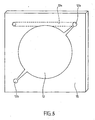
- Such space can be created by etching a recess in the bottom surface of first substrate 15, the bottom substrate 16 presenting a flat surface towards the inside of space 12 such as shown in FIGURES 3 and 4 .
- Such space can also be created in the bottom substrate 16 by wet or dry etch as will be described further on.
- the second substrate can also be advantageously replaced directly by the vibrating element 18 which for the purpose of protection has been suitably passivated as described in EP-A-0 923 957 .
- space 12 is preferably of a round cross-section in order to facilitate filling and air evacuation and may incorporate a geometry for creating passive valves at its inlet and outlet. It may further be dimensioned or complemented, e.g. by connecting to an internal or external dosage buffer volume 12a, to contain a required dosage amount such that principal volume 12 together with buffer volume 12a correspond to a desired unit dose which may be larger than the internal volume of space 12.
- the desired unit dose may have a maximum dosage corresponding to the total volume of space 12, i.e. of principal volume 12 plus buffer volume 12a. In such a way space 12 is at first, e.g.
- buffer volume 12a allows for the spray device to be filled with a different dose for each intended use, ranging from the approximate volume of space 12 to the total volume of space 12 plus buffer volume 12a.
- Buffer volume 12a is realised preferably as a capillary meander or other geometrical configuration having a cross-section that facilitates capillary action thus providing easier priming of space 12 and buffer 12a.
- capillary channel 12b for supplying the liquid substance to and allowing exiting from space 12 is provided as known from the mentioned prior art.
- capillary channel can be advantageously configured to act as a passive valve, which is known as such, to allow for the liquid substance to enter and exit the space.
- At least one outlet nozzle 19 and at least one output channel 20 for connecting space 12 to each outlet nozzle 19 are further provided in the thinner membrane section 15a of substrate 15. It is of course important that the output channel 20 has straight sidewalls so as to be able to define the pressure drop across the channel when a droplet is ejected, as already explained in detail in the above-mentioned prior art EP-A-0 923 957 .
- a vibrating element such as a piezoelectric element 18 is disposed on the housing to vibrate the liquid substance in space 12.
- the vibrating element is arranged directly on the first substrate 15 or on a thinner section of the second substrate 16, e.g. acting as a membrane for transmitting a certain compression as well as the vibration to the liquid contained in space 12 and vibration to the total structure such as described in the above-mentioned prior art.
- the liquid is excited at an appropriate frequency and under the appropriate pressure, it will be ejected as a spray of droplets through the outlet nozzles with a very low exit velocity.
- the preferred operation is at the fundamental resonance frequency of vibrating element 18 or at subsequent harmonics.
- output channel 20 consists of a lower part 20a and an upper part 20b.
- Lower part 20a of output channel 20 has a larger diameter than upper part 20b and can have the same or a different length as the upper part.
- Lower part 20a is arranged adjacent space 12 containing the liquid substance which is to be expelled.
- the excited liquid is forced at a higher pressure into the upper part 20b of the output channel.
- the eventual size of the droplet results mainly from the liquid volume that is contained in the smaller upper part 20b.
- the outlet nozzle is also straight without any notching at its periphery, thanks to the inventive method of manufacturing the spray device, as will be explained in detail further on.
- the diameter and the volume of the expelled droplet depend mainly on the pressure drop across the output channel and also on the applied voltage, amplitude and frequency.
- the Applicant has found it to be possible, and practical, with the present structure to vary the droplet size by only varying the voltage applied to the vibrating element 18.
- Applicant has found that at virtually no input pressure, at 30 V and approximately 250 kHz applied to the vibrating element, more than 80% of the droplets were smaller than the diameter of the upper part of channel 20b.
- the droplet size it is possible to vary the droplet size, but with it the flow rate and also the exit velocity by varying the applied voltage so that a programmable platform for a liquid droplet spray device may be obtained. Consequently, it is possible to provide largely identical liquid droplet spray devices for different applications by simply varying the applied voltage.
- the same spray device may be used as an inhaler for systemic, deep lung applications which require droplets of less than 3,3 ⁇ m or for upper lung treatment which requires droplets of less than 5,6 ⁇ m or for various types of liquids which require a different energy input to obtain the same droplet size.
- such a liquid droplet spray device is manufactured by using the following method which is explained whilst referring to FIGURES 4 and 5 .
- the structure of the present liquid droplet spray device may also be realised by sandwiching different materials such as Si, SiO 2 , SiN, SU-8, metal, and the like, in suitable combinations, or by successive depositions of such materials.
- a detailed explanation of the manufacturing of the first substrate 15 will be provided here. Indeed, this substrate has a more complicated shape than the bottom substrate.
- step 1 of FIGURE 4 first an oxide mask is deposited on both surfaces of a substrate which will form the first substrate 15.
- step 2 the top surface is etched using for example a wet etching process, advantageously with an etch stopper (not shown) so as to obtain the thinner membrane sections 15a.
- step 3 two possibilities exist.
- the oxide at the bottom surface of first substrate 15 is opened, defining large openings corresponding to the lower, wider, parts 20a of output channels 20, in this case space 12 is machined into substrate 16.
- the oxide is etched partially in order to shape space 12 into substrate 15 followed by an additional etch which defines the large openings corresponding to the lower, wider, parts 20a of output channels 20 (not fully shown in Fig. 4 ).
- step 4 after a photo-resist has been applied defining the small openings corresponding to upper parts 20b of output channels 20, a plasma etching, preferably by using an ICP (Inductively Controlled Plasma) technique, of the silicon is carried out to obtain the shape of the small openings and is stopped at a suitable depth.
- ICP Inductively Controlled Plasma
- this differential plasma-etching step is stopped before the etching pierces, i.e. traverses the substrate.
- the present inventors have found that when piercing the substrate during such plasma-etching step, notching occurs resulting in slightly tapered outlet nozzles which could have a negative influence on the control of the droplet size and on its directivity when ejected from the nozzle.
- a third plasma etch step is carried out either to create the space 12 locally into substrate 15 and to open upper channel part 20b or the third plasma etch step is carried out over the entire wafer surface in order to open upper channel part 20b in case that space 12 is to be machined into substrate 16, as shown respectively in steps 7b or 7a of Fig 4 .
- the present invention it is possible to avoid notching and thereby obtain straight through holes, i.e. straight step-shaped output channel by a correct choice of the surfaces to be differentially etched.
- the ratio of the large etching surface (corresponding to space 12) to the small etching surface (corresponding to the upper, narrow channel part 20b) should be chosen such that the etching speed will be low enough in the small etching surface that notching is avoided.
- the wafer is turned and the top surface of the first substrate 15 is etched with the same plasma etcher, preferably in only one step which is stopped in the passivation mode in order to provide a hydrophobic quality of that top surface.
- This innovative etching process is called differential etching because the larger exposed surface will be etched faster than the smaller exposed surface, i.e. the "bottom" of the narrow channel part.
- the narrower channel will be etched to become slightly longer so as to eventually correspond to the actual desired dimensions of upper part 20b of output channel 20, but this narrower part will also be "pushed forward" with respect to the larger opened portion of the silicon by the etching so as to eventually pierce the substrate with the third plasma-etching step.
- the thinner section for accommodating the piezoelectric element may be obtained by machining it into silicon or Pyrex wafers.
- This second substrate may also be directly replaced by a suitably passivated vibrating element 18. Any further shape changes may also be conceived by applying the usual techniques in the field.
- step 7a and 7b in figure 4 the bottom surface of first substrate 15 and the top surface of second substrate 16 are bonded together, preferably by using anodic bonding so as to form the housing of the liquid droplet spray device thereby enclosing space 12.
- first substrate 15 it is possible to apply a further differential etching step to first substrate 15 to etch away a part of first substrate 15 so as to obtain space 12 directly in first substrate 15. It is further also possible to etch, either at the same time or in a separate step, the buffer volume 12a and/or passive valves 12b. Then, second substrate 16 may be applied to first substrate 15 so as to close space 12.
- second substrate 16 instead of using the second substrate, it is also possible to directly bond the vibrating element 18, whose surface is preferably suitably treated and protected beforehand, to first substrate 15 so as to enclose space 15.
- a selective hydrophilic coating such as an amorphous material such as SiO2, may further be applied to provide a protective layer around the inside surface of space 12 and/or of the output channels 20 to avoid any contamination of the liquid substance by the material of these surfaces and to improve wettability in certain parts.
- This hydrophilic coating which may be applied as a selective, patterned coating and is advantageously coupled with a selective, patterned hydrophobic coating in certain areas of space 12 and on the outside of first substrate 15.
- a hard amorphous carbon film may be provided on first substrate 15 in order to maintain the protective aspect of its surfaces and at the same time to reduce the internal and external stiction due to capillary forces in space 12, and especially on the outside of substrate 15.
- This hard amorphous carbon film e.g. diamond-like carbon (DLC) or fluorinated DLC (F*DLC) is provided, preferably in a selective patterned manner in these areas.
- DLC diamond-like carbon
- F*DLC fluorinated DLC
- Other hydrophobic coatings such as nitride or Teflon might be deposited by spinning and curing, by plasma or by other suitable methods. Such selective film coating also allows for a more complete emptying of space 12 and avoids stiction of liquid on the outside surface of substrate 15 due to low surface energy.
- a protective layer 25 such as an oxide, as shown in step 2 of Figures 6a and 6b .
- a resist film is formed on the bottom surface of first substrate 15 and an opening is defined corresponding to the lower wider portion 20a of output channel 20 (not shown).
- the lower portion 20a is formed by etching first substrate 15 so as to obtain the lower portion 20a of the output channel, as shown in step 3 of figures 6a and 6b .
- first substrate 15 is substantially ready to be bonded with second substrate 16 in which space 12 has been machined as described earlier.
- the sidewalls of the lower portion 20 a are also covered with a protective layer same as the oxide protecting the inner sidewalls of the upper portion 20b, as shown in step 4 of figure 6b .
- another resist is applied on the bottom surface of first substrate 15 and an opening is defined corresponding to the recess which is to constitute space 12 (not shown).
- the bottom surface of first substrate 15 is again etched so as to obtain the recess, forming space 12, as shown in step 5 of figure 6b .
- the oxide is removed as shown in step 6 of figure 6b .
- the liquid droplet spray device according to the present invention having a step-shaped output channel with a recess whereby the outlet nozzle at the end of the output channel does not show notching influences when the substrate is pierced.
- the steps used here can be conventional steps thus allowing for a reliable manufacturing of the liquid droplet spray device.
- the same liquid droplet spray device may not only be used for an inhaler in respiratory therapies, but it may generally be used for creating nebulized liquids of different physico-chemical compositions, e.g. using aqueous or alcoholic or other liquid substances.
Claims (17)
- Flüssigkeitströpfchen-Versprühvorrichtung zum Versprühen einer flüssigen Substanz, mit:einem Gehäuse, das zumindest aus einem ersten Träger (15) mit mindestens einem Membranteil (15a) besteht, der dünner als der Rest des ersten Trägers (15) ist;einem Zwischenraum (12) in dem Gehäuse zum Aufnehmen der flüssigen Substanz;Mitteln zum Zuführen der flüssigen Substanz zu dem Zwischenraum (12);Auslassmitteln, die in dem Membranteil (15a) angeordnet sind und mindestens eine Auslassdüse (19), die in einer ersten Hauptfläche des ersten Trägers (15) angeordnet ist, und mindestens einen Auslasskanal (20) aufweisen, der den Zwischenraum (12) mit jeder der mindestens einen Auslassdüse (19) verbindet; undeinem Schwingelement (18), das so eingerichtet ist, dass es Flüssigkeit in dem Zwischenraum (12) in Schwingung versetzt, um die flüssige Substanz als eine Sprühflüssigkeit durch die Auslassdüse (19) auszustoßen,dadurch gekennzeichnet, dass
jeder Auslasskanal (20) eine abgestufte Gestalt mit einem unteren Teil (20a) und einem oberen Teil (20b) hat, wobei der untere Teil angrenzend an den Zwischenraum (12) angeordnet ist und einen größeren Durchmesser als der obere Teil (20b) hat und jeder Auslasskanalteil (20a, 20b) gerade Seitenwände hat, und
der Rest des ersten Trägers (15) aus Teilen besteht, die dicker als der Membranteil (15a) sind und die sich auf der Seite der ersten Hauptfläche des ersten Trägers (15) befinden. - Flüssigkeitströpfchen-Versprühvorrichtung nach Anspruch 1, die weiterhin dadurch gekennzeichnet ist, dass der Rest des ersten Trägers (15) aus dickeren Teilen besteht, die Seitenwände haben, die von den Membranteilen (15a) weg führen.
- Flüssigkeitströpfchen-Versprühvorrichtung nach Anspruch 1 oder 2, die weiterhin dadurch gekennzeichnet ist, dass der erste Träger (15) in seiner anderen Hauptfläche eine Aussparung hat, die den Zwischenraum (12) bildet.
- Flüssigkeitströpfchen-Versprühvorrichtung nach Anspruch 1, die weiterhin dadurch gekennzeichnet ist, dass das Schwingelement (18) rund ist und einen kleineren Querschnitt als der Zwischenraum (12) hat und so eingerichtet ist, dass es auf seiner Grundresonanzfrequenz oder den nachfolgenden Oberschwingungen arbeitet, um die flüssige Substanz als eine Sprühflüssigkeit durch die Auslassdüse (19) auszustoßen.
- Flüssigkeitströpfchen-Versprühvorrichtung nach Anspruch 3, dadurch gekennzeichnet, dass das Gehäuse weiterhin einen zweiten Träger (16) aufweist und der Zwischenraum (12), der von der Aussparung gebildet wird, von dem zweiten Träger (16) verschlossen wird.
- Flüssigkeitströpfchen-Versprühvorrichtung nach Anspruch 1 oder 2, dadurch gekennzeichnet, dass das Gehäuse weiterhin einen zweiten Träger (16) aufweist und der Zwischenraum (12) in dem zweiten Träger (16) vorgesehen ist.
- Flüssigkeitströpfchen-Versprühvorrichtung nach einem der vorhergehenden Ansprüche, die weiterhin ein passives Ventil (12b) aufweist, das in physischer Kombination mit dem Zwischenraum (12) so angeordnet ist, dass es den gleichmäßigen Betrieb der Vorrichtung dadurch ermöglicht, dass es den Zwischenraum (12) gleichmäßig mit der flüssigen Substanz füllt.
- Flüssigkeitströpfchen-Versprühvorrichtung nach einem der vorhergehenden Ansprüche, dadurch gekennzeichnet, dass der Zwischenraum aus einem Hauptvolumen (12) und einem Puffervolumen (12a) besteht, wobei das Puffervolumen so dimensioniert ist, dass das Gesamtvolumen des Hauptvolumens (12) zusammen mit dem Puffervolumen (12a) einer maximalen Dosis entspricht, sodass eine gewünschte variable Dosis in Abhängigkeit von dem speziellen Verwendungszweck der Versprühvorrichtung in dem Zwischenraum aufgenommen werden kann, wobei die variable Dosis gleich der maximalen Dosis oder kleiner als diese ist.
- Verfahren zur Herstellung einer Flüssigkeitströpfchen-Versprühvorrichtung zum Versprühen einer flüssigen Substanz nach Anspruch 6, mit den folgenden Schritten:a) Abscheiden einer Oxidmaske auf beiden Hauptflächen eines Siliciumträgers, der den ersten Träger (15) bilden soll;b) Ätzen einer ersten Hauptfläche des ersten Trägers (15), um die dünneren Membranteile (15a) zu erhalten;c) Aufbringen eines ersten Fotoresists, das große Öffnungen definiert, die dem unteren Teil (20a) der Auslasskanäle (20) entsprechen, auf die andere Hauptfläche des ersten Trägers (15) und anschließend Wegätzen der Oxidmaske, um einen Zugang zu dem Silicium des ersten Trägers (15) freizulegen;d) Aufbringen eines zweiten Fotoresists, um kleine Öffnungen zu definieren, die dem oberen Teil (20b) der Auslasskanäle (20) entsprechen, und anschließend Verwenden des partiellen Plasma-Ätzens des Siliciums, um einen schmalen Kanal zu erhalten, der schmaler und kürzer ist, als der eigentliche obere Teil (20b) sein wird, und Ablösen des zweiten Fotoresists;e) Ätzen des freiliegenden Siliciums unter Verwendung des differentiellen Plasma-Ätzens, bis der Träger (15) fast perforiert ist;f) Verwenden des Plasma-Ätzens auf der anderen Hauptfläche des ersten Trägers (15), um den Träger (15) zu perforieren, wobei das Verhältnis der zu ätzenden Fläche zu der Fläche, die der Düsenöffnung des oberen Teils (20b) entspricht, so ist, dass die Ätzgeschwindigkeit der Düse so gering ist, dass ein Einkerben der Auslassdüse (19) vermieden wird;g) Ätzen eines zweiten Siliciumträgers, um den zweiten Träger (16) mit einem Zwischenraum (12) darin auszubilden;h) Verbinden des ersten Trägers (15) mit dem zweiten Träger (16), um das Gehäuse der Flüssigkeitströpfchen-Versprühvorrichtung auszubilden;i) Bereitstellen von Mitteln zum Zuführen der flüssigen Substanz zu dem Zwischenraum (12) undj) Bereitstellen des Schwingelements (18).
- Verfahren zur Herstellung einer Flüssigkeitströpfchen-Versprühvorrichtung zum Versprühen einer flüssigen Substanz nach Anspruch 3, mit den folgenden Schritten:a) Abscheiden einer Oxidmaske auf beiden Hauptflächen eines Siliciumträgers, der den ersten Träger (15) bilden soll;b) Ätzen einer ersten Hauptfläche des ersten Trägers (15), um die dünneren Membranteile (15a) zu erhalten;c) Aufbringen eines ersten Fotoresists, das große Öffnungen definiert, die dem unteren Teil (20a) der Auslasskanäle (20) entsprechen, auf die andere Hauptfläche des ersten Trägers (15) und anschließend Wegätzen der Oxidmaske, um einen Zugang zu dem Silicium des ersten Trägers (15) freizulegen;d) Aufbringen eines zweiten Fotoresists, um kleine Öffnungen zu definieren, die dem oberen Teil (20b) der Auslasskanäle (20) entsprechen, und anschließend Verwenden des partiellen Plasma-Ätzens des Siliciums, um einen schmalen Kanal zu erhalten, der schmaler und kürzer ist, als der eigentliche obere Teil (20b) sein wird, und Ablösen des zweiten Fotoresists;e) Ätzen des freiliegenden Siliciums unter Verwendung des differentiellen Plasma-Ätzens, bis der Träger (15) fast perforiert ist;f) Aufbringen eines dritten Fotoresists, um eine große Öffnung zu definieren, die dem Zwischenraum (12) entspricht, und anschließend Verwenden des Plasma-Ätzens, um die Aussparung zu erhalten, die den Zwischenraum (12) bildet, und um den Träger (15) zu perforieren, wobei das Verhältnis der zu ätzenden Fläche, die dem Zwischenraum entspricht, zu der Fläche, die der Düsenöffnung des oberen Teils (20b) entspricht, so ist, dass die Ätzgeschwindigkeit der Düse so gering ist, dass ein Einkerben der Auslassdüse (19) vermieden wird;g) Bereitstellen von Mitteln zum Zuführen der flüssigen Substanz zu dem Zwischenraum (12);h) Bereitstellen des Schwingelements (18) undi) Verbinden des ersten Trägers (15) mit dem Schwingelement (18), um das Gehäuse der Flüssigkeitströpfchen-Versprühvorrichtung auszubilden.
- Verfahren zur Herstellung einer Flüssigkeitströpfchen-Versprühvorrichtung zum Versprühen einer flüssigen Substanz nach Anspruch 3, mit den folgenden Schritten:a) Abscheiden einer Oxidmaske auf beiden Hauptflächen eines Siliciumträgers, der den ersten Träger (15) bilden soll;b) Ätzen einer ersten Hauptfläche des ersten Trägers (15), um die dünneren Membranteile (15a) zu erhalten;c) Aufbringen eines ersten Fotoresists, das große Öffnungen definiert, die den unteren Teilen (20a) der Auslasskanäle (20) entsprechen, auf die andere Hauptfläche des ersten Trägers (15) und anschließend Wegätzen der Oxidmaske, um einen Zugang zu dem Silicium des ersten Trägers (15) freizulegen;d) Aufbringen eines zweiten Fotoresists, um kleine Öffnungen zu definieren, die den oberen Teilen (20b) der Auslasskanäle (20) entsprechen, und anschließend Verwenden des partiellen Plasma-Ätzens des Siliciums, um einen schmalen Kanal zu erhalten, der schmaler und kürzer ist, als der eigentliche obere Teil (20b) sein wird, und Ablösen des zweiten Fotoresists;e) Ätzen des freiliegenden Siliciums unter Verwendung des differentiellen Plasma-Ätzens, bis der Träger (15) fast perforiert ist;f) Aufbringen eines dritten Fotoresists, um eine große Öffnung zu definieren, die dem Zwischenraum (12) entspricht, und anschließend Verwenden des Plasma-Ätzens, um die Aussparung zu erhalten, die den Zwischenraum (12) bildet, und um den Träger (15) zu perforieren, wobei das Verhältnis der zu ätzenden Fläche, die dem Zwischenraum entspricht, zu der Fläche, die der Düsenöffnung des oberen Teils (20b) entspricht, so ist, dass die Ätzgeschwindigkeit der Düse so gering ist, dass ein Einkerben der Auslassdüse (19) vermieden wird;g) Ätzen eines zweiten Siliciumträgers, um den zweiten Siliciumträger (16) auszubilden;h) Verbinden des ersten Trägers (15) mit dem zweiten Träger (16), um das Gehäuse der Flüssigkeitströpfchen-Versprühvorrichtung auszubilden;i) Bereitstellen von Mitteln zum Zuführen der flüssigen Substanz zu dem Zwischenraum (12) undh) Bereitstellen des Schwingelements (18).
- Verfahren zur Herstellung einer Flüssigkeitströpfchen-Versprühvorrichtung nach Anspruch 9, 10 oder 11, das weiterhin nach dem Schritt e) und vor dem Schritt g) einen Schritt des Aufbringens eines selektiven hydrophilen Überzugs aufweist, um eine Schutzschicht um die Innenfläche des Zwischenraums (12) und/oder der Auslasskanäle (20) herzustellen, um eine Verunreinigung der flüssigen Substanz mit dem Material dieser Flächen zu vermeiden und die Benetzbarkeit in bestimmten Teilen zu verbessern.
- Verfahren zur Herstellung einer Flüssigkeitströpfchen-Versprühvorrichtung nach Anspruch 12, das weiterhin den folgenden Schritt aufweist: Aufbringen eines selektiven hydrophoben Überzugs in den Bereichen des Zwischenraums (12), die den hydrophilen Überzug nicht haben, und auf der Außenfläche des ersten Trägers (15).
- Verfahren zur Herstellung einer Flüssigkeitströpfchen-Versprühvorrichtung nach Anspruch 11, das weiterhin den folgenden zusätzlichen Schritt aufweist: Plasma-Ätzen der ersten Hauptfläche des ersten Trägers (15), das im Passivierungsmodus unterbrochen wird, um eine hydrophobe Oberflächengüte zu erhalten, wobei die gleiche Produktionsanlage wie für die anderen differentiellen Plasma-Ätzschritte verwendet wird.
- Verfahren zur Herstellung einer Flüssigkeitströpfchen-Versprühvorrichtung nach Anspruch 13 oder 14, das weiterhin den Schritt des Aufbringens eines harten amorphen Kohlenstofffilms auf dem hydrophoben Überzug aufweist.
- Verfahren zur Herstellung einer Flüssigkeitströpfchen-Versprühvorrichtung zum Versprühen einer flüssigen Substanz nach Anspruch 3, mit den folgenden Schritten:a) Abscheiden einer Oxidmaske auf beiden Hauptflächen eines Siliciumträgers, der den ersten Träger (15) bilden soll;b) Ätzen einer ersten Hauptfläche des ersten Trägers (15), um die dünneren Membranteile (15a) zu erhalten;c) Aufbringen eines ersten Fotoresists, das schmale Öffnungen definiert, die dem oberen Teil (20b) der Auslasskanäle (20) entsprechen, auf die andere Hauptfläche des ersten Trägers (15) und anschließend Wegätzen der Oxidmaske, um einen Zugang zu dem Silicium des ersten Trägers (15) freizulegen;d) Ätzen des Siliciums, um ein Durchgangsloch, das durch den ersten Träger (15) geht, so zu erhalten, dass keine Einkerbung auftritt;e) Aufbringen einer Schutzschicht (25) auf die inneren Seitenwände des Durchgangslochs;f) Aufbringen eines zweiten Fotoresists auf die andere Hauptfläche des ersten Trägers (15), um große Öffnungen zu definieren, die dem unteren Teil (20a) der Auslasskanäle (20 entsprechen, und anschließend Ätzen des Siliciums, um einen großen Kanal zu erhalten, der dem unteren Teil (20a) entspricht, und Ablösen des zweiten Fotoresists;g) Aufbringen einer Schutzschicht (25) auf die inneren Seitenwände des nunmehr abgestuften Durchgangslochs, das dem abgestuften Auslasskanal (20) entspricht;h) Aufbringen eines dritten Fotoresists auf die andere Hauptfläche des ersten Trägers (15), um eine große Öffnung zu definieren, die dem Zwischenraum (12) entspricht, und anschließend Ätzen des Siliciums, um die abgestufte Aussparung zu erhalten, die den Zwischenraum (12) bildet;i) Entfernen der Schutzschicht von den inneren Seitenwänden des Durchgangslochs;j) Bereitstellen von Mitteln zum Zuführen der flüssigen Substanz zu dem Zwischenraum (12);k) Bereitstellen des Schwingelements (18) undl) Verbinden des ersten Trägers (15) mit dem Schwingelement (18), um das Gehäuse der Flüssigkeitströpfchen-Versprühvorrichtung auszubilden.
- Verfahren zur Herstellung eines Düsenkörpers einer Flüssigkeitströpfchen-Versprühvorrichtung, der aus einem Träger mit mindestens einem Membranteil besteht, der dünner als der Rest des Trägers ist, wobei Auslassmittel in dem Membranteil angeordnet sind, die mindestens eine Auslassdüse (19), die in einer ersten Hauptfläche des ersten Trägers (15) angeordnet ist, und mindestens einen abgestuften Auslasskanal (20) aufweisen, der eine Hauptfläche des Trägers mit der anderen Hauptfläche des Trägers verbindet, wobei der Auslasskanal (20) gerade Seitenwände sowie einen breiten unteren Teil (20a) und einen schmalen oberen Teil (20b) hat, mit den folgenden Schritten:a) Abscheiden einer Oxidmaske auf beiden Flächen des Trägers, der den Düsenkörper bilden soll;b) Ätzen einer ersten Hauptfläche des Trägers, um die dünneren Membranteile (15a) zu erhalten;c) Aufbringen eines ersten Fotoresists, das große Öffnungen definiert, die den unteren Teilen (20a) der Auslasskanäle (20) entsprechen, auf die andere Hauptfläche des Trägers und anschließend Wegätzen der Oxidmaske, um einen Zugang zu dem Silicium des Trägers freizulegen;d) Aufbringen eines zweiten Fotoresists, um kleine Öffnungen zu definieren, die den oberen Teilen (20b) der Auslasskanäle (20) entsprechen, und anschließend Verwenden des partiellen Plasma-Ätzens des Siliciums, um einen schmalen Kanal zu erhalten, der schmaler und kürzer ist, als der eigentliche obere Teil (20b) sein wird, und Ablösen des zweiten Fotoresists;e) Ätzen des freiliegenden Siliciums unter Verwendung des differentiellen Plasma-Ätzens, bis der Träger fast perforiert ist; undf) Plasma-Ätzen der anderen Hauptfläche des Trägers, um den Träger (15) zu perforieren, wobei das Verhältnis der zu ätzenden Fläche des Trägers zu der Fläche, die der Düsenöffnung des oberen Teils (20b) entspricht, so ist, dass die Ätzgeschwindigkeit der Düse so gering ist, dass ein Einkerben der Düse vermieden wird.
Priority Applications (1)
| Application Number | Priority Date | Filing Date | Title |
|---|---|---|---|
| EP02004089A EP1273355B1 (de) | 2001-02-23 | 2002-02-25 | Verfahren zur Herstellung eines Tröpfchen-Verneblers und ein solcher Vernebler |
Applications Claiming Priority (3)
| Application Number | Priority Date | Filing Date | Title |
|---|---|---|---|
| EP01103653A EP1236517A1 (de) | 2001-02-23 | 2001-02-23 | Verfahren zur Herstellung eines Tröpfchen-Verneblers und ein solcher Vernebler |
| EP01103653 | 2001-02-23 | ||
| EP02004089A EP1273355B1 (de) | 2001-02-23 | 2002-02-25 | Verfahren zur Herstellung eines Tröpfchen-Verneblers und ein solcher Vernebler |
Publications (2)
| Publication Number | Publication Date |
|---|---|
| EP1273355A1 EP1273355A1 (de) | 2003-01-08 |
| EP1273355B1 true EP1273355B1 (de) | 2010-03-31 |
Family
ID=26076478
Family Applications (1)
| Application Number | Title | Priority Date | Filing Date |
|---|---|---|---|
| EP02004089A Expired - Lifetime EP1273355B1 (de) | 2001-02-23 | 2002-02-25 | Verfahren zur Herstellung eines Tröpfchen-Verneblers und ein solcher Vernebler |
Country Status (1)
| Country | Link |
|---|---|
| EP (1) | EP1273355B1 (de) |
Families Citing this family (12)
| Publication number | Priority date | Publication date | Assignee | Title |
|---|---|---|---|---|
| US7017829B2 (en) | 2003-04-14 | 2006-03-28 | S. C. Johnson & Son, Inc. | Atomizer wicking system |
| EP1468748A1 (de) * | 2003-04-15 | 2004-10-20 | Microflow Engineering SA | Vorrichtung zur Erzeugung von Flüsigkeitströpfchen und Düsenkörper |
| DE102004006452B4 (de) * | 2004-02-05 | 2006-04-20 | Ing. Erich Pfeiffer Gmbh | Mikrodosiervorrichtung |
| DE102004011726A1 (de) | 2004-03-05 | 2005-09-22 | Ing. Erich Pfeiffer Gmbh | Dosiervorrichtung |
| US7560039B2 (en) | 2004-09-10 | 2009-07-14 | Lexmark International, Inc. | Methods of deep reactive ion etching |
| EP1792662A1 (de) | 2005-11-30 | 2007-06-06 | Microflow Engineering SA | Tropferspendervorrichtung |
| DE102006061506B4 (de) | 2006-12-15 | 2008-10-30 | Ing. Erich Pfeiffer Gmbh | Dosiervorrichtung |
| EP1952896B1 (de) | 2007-02-01 | 2012-11-07 | EP Systems SA | Tropfenspender |
| DE602008003319D1 (de) | 2008-06-03 | 2010-12-16 | Microflow Eng Sa | Spendervorrichtung für flüchtige flüssige Tröpfchen |
| BR112013011411A2 (pt) | 2010-11-08 | 2019-09-24 | British American Tobacco Investiments Ltd | dispositivo de pulverização de gotículas líquidas |
| JP7358374B2 (ja) * | 2018-03-21 | 2023-10-10 | ソフトハレ エヌヴイ | 吸入装置用スプレーノズル |
| CN112090603B (zh) * | 2019-06-17 | 2022-11-08 | 苏州天健云康信息科技有限公司 | 微流体器件及其制造方法 |
Family Cites Families (6)
| Publication number | Priority date | Publication date | Assignee | Title |
|---|---|---|---|---|
| DE59209764D1 (de) * | 1992-05-20 | 1999-12-09 | Ibm | Verfahren zum Erzeugen einer mehrstufigen Struktur in einem Substrat |
| US6142607A (en) * | 1996-08-07 | 2000-11-07 | Minolta Co., Ltd. | Ink-jet recording head |
| WO1998051506A1 (fr) * | 1997-05-14 | 1998-11-19 | Seiko Epson Corporation | Procede de formation d'ajutage pour injecteurs et procede de fabrication d'une tete a jet d'encre |
| CH694453A5 (de) * | 1998-07-24 | 2005-01-31 | Genspec Sa | Mikromechanisch hergestellte Düse zur Erzeugung reproduzierbarer Tröpfchen. |
| ES2149748T3 (es) * | 1998-12-01 | 2007-06-16 | Microflow Engineering Sa | Inhalador con nebulizador de ondas ultrasonicas que presenta unas aberturas de boquilla superpuestas sobre las crestas de un patron de onda estacionaria. |
| JP3575373B2 (ja) * | 1999-04-19 | 2004-10-13 | 株式会社村田製作所 | 外力検知センサの製造方法 |
-
2002
- 2002-02-25 EP EP02004089A patent/EP1273355B1/de not_active Expired - Lifetime
Also Published As
| Publication number | Publication date |
|---|---|
| EP1273355A1 (de) | 2003-01-08 |
Similar Documents
| Publication | Publication Date | Title |
|---|---|---|
| US8020973B2 (en) | Method of manufacturing a liquid droplet spray device and such spray device | |
| US6405934B1 (en) | Optimized liquid droplet spray device for an inhaler suitable for respiratory therapies | |
| EP0923957B1 (de) | Tröpfchen-Vernebler und Zerstäubungsdüse für einen therapeutischen Inhalator | |
| EP1273355B1 (de) | Verfahren zur Herstellung eines Tröpfchen-Verneblers und ein solcher Vernebler | |
| EP1993646B1 (de) | Zerstäuberporeneinstellung für die intrapulmonale freisetzung von formulierungen in aerosolform | |
| EP1468749B1 (de) | Flüssigkeitströpfchen- Spritzvorrichtung und Düsenkörper | |
| US7594507B2 (en) | Thermal generation of droplets for aerosol | |
| US6722582B2 (en) | Liquid droplet spray device | |
| US20130134131A1 (en) | Process for manufacturing an integrated membrane of nozzles in mems technology for a spray device and spray device using such membrane | |
| MX2008011252A (es) | Tobera de remolino. | |
| EP1287904B1 (de) | Sprühvorrichtung für Flüssigkeiten | |
| EP1005916A1 (de) | Inhalator mit Ultraschallzerstäuber dessen Düsenöffnungen den Amplitudenmaxima eines stehenden Wellenmusters überlagert sind | |
| EP1200198B1 (de) | Aktorbauglied für einen mikrozerstäuber und verfahren zu seiner herstellung |
Legal Events
| Date | Code | Title | Description |
|---|---|---|---|
| PUAI | Public reference made under article 153(3) epc to a published international application that has entered the european phase |
Free format text: ORIGINAL CODE: 0009012 |
|
| AK | Designated contracting states |
Kind code of ref document: A1 Designated state(s): AT BE CH CY DE DK ES FI FR GB GR IE IT LI LU MC NL PT SE TR |
|
| AX | Request for extension of the european patent |
Free format text: AL;LT;LV;MK;RO;SI |
|
| 17P | Request for examination filed |
Effective date: 20030530 |
|
| AKX | Designation fees paid |
Designated state(s): DE FR GB |
|
| 17Q | First examination report despatched |
Effective date: 20040927 |
|
| GRAP | Despatch of communication of intention to grant a patent |
Free format text: ORIGINAL CODE: EPIDOSNIGR1 |
|
| GRAS | Grant fee paid |
Free format text: ORIGINAL CODE: EPIDOSNIGR3 |
|
| GRAA | (expected) grant |
Free format text: ORIGINAL CODE: 0009210 |
|
| AK | Designated contracting states |
Kind code of ref document: B1 Designated state(s): DE FR GB |
|
| REG | Reference to a national code |
Ref country code: GB Ref legal event code: FG4D |
|
| REF | Corresponds to: |
Ref document number: 60235785 Country of ref document: DE Date of ref document: 20100512 Kind code of ref document: P |
|
| PLBE | No opposition filed within time limit |
Free format text: ORIGINAL CODE: 0009261 |
|
| STAA | Information on the status of an ep patent application or granted ep patent |
Free format text: STATUS: NO OPPOSITION FILED WITHIN TIME LIMIT |
|
| 26N | No opposition filed |
Effective date: 20110104 |
|
| PGFP | Annual fee paid to national office [announced via postgrant information from national office to epo] |
Ref country code: GB Payment date: 20141215 Year of fee payment: 14 |
|
| REG | Reference to a national code |
Ref country code: GB Ref legal event code: 732E Free format text: REGISTERED BETWEEN 20150212 AND 20150219 |
|
| REG | Reference to a national code |
Ref country code: FR Ref legal event code: TP Owner name: APTAR FRANCE SAS, FR Effective date: 20150310 |
|
| PGFP | Annual fee paid to national office [announced via postgrant information from national office to epo] |
Ref country code: DE Payment date: 20141119 Year of fee payment: 14 |
|
| REG | Reference to a national code |
Ref country code: DE Ref legal event code: R082 Ref document number: 60235785 Country of ref document: DE Representative=s name: TBK, DE |
|
| REG | Reference to a national code |
Ref country code: DE Ref legal event code: R082 Ref document number: 60235785 Country of ref document: DE Representative=s name: TBK, DE Effective date: 20150520 Ref country code: DE Ref legal event code: R081 Ref document number: 60235785 Country of ref document: DE Owner name: APTAR FRANCE SAS, FR Free format text: FORMER OWNER: MICROFLOW ENGINEERING S.A., NEUENBURG/NEUCHATEL, CH Effective date: 20150520 |
|
| REG | Reference to a national code |
Ref country code: FR Ref legal event code: PLFP Year of fee payment: 15 |
|
| REG | Reference to a national code |
Ref country code: DE Ref legal event code: R119 Ref document number: 60235785 Country of ref document: DE |
|
| GBPC | Gb: european patent ceased through non-payment of renewal fee |
Effective date: 20160225 |
|
| PG25 | Lapsed in a contracting state [announced via postgrant information from national office to epo] |
Ref country code: GB Free format text: LAPSE BECAUSE OF NON-PAYMENT OF DUE FEES Effective date: 20160225 Ref country code: DE Free format text: LAPSE BECAUSE OF NON-PAYMENT OF DUE FEES Effective date: 20160901 |
|
| REG | Reference to a national code |
Ref country code: FR Ref legal event code: PLFP Year of fee payment: 16 |
|
| REG | Reference to a national code |
Ref country code: FR Ref legal event code: PLFP Year of fee payment: 17 |
|
| PGFP | Annual fee paid to national office [announced via postgrant information from national office to epo] |
Ref country code: FR Payment date: 20210225 Year of fee payment: 20 |