EP1445404A2 - Türschlossvorrichtung - Google Patents
Türschlossvorrichtung Download PDFInfo
- Publication number
- EP1445404A2 EP1445404A2 EP20040002089 EP04002089A EP1445404A2 EP 1445404 A2 EP1445404 A2 EP 1445404A2 EP 20040002089 EP20040002089 EP 20040002089 EP 04002089 A EP04002089 A EP 04002089A EP 1445404 A2 EP1445404 A2 EP 1445404A2
- Authority
- EP
- European Patent Office
- Prior art keywords
- housing
- latch mechanism
- door lock
- lock device
- case
- Prior art date
- Legal status (The legal status is an assumption and is not a legal conclusion. Google has not performed a legal analysis and makes no representation as to the accuracy of the status listed.)
- Withdrawn
Links
- 230000000149 penetrating effect Effects 0.000 claims 1
- XLYOFNOQVPJJNP-UHFFFAOYSA-N water Substances O XLYOFNOQVPJJNP-UHFFFAOYSA-N 0.000 description 29
- 239000011347 resin Substances 0.000 description 24
- 229920005989 resin Polymers 0.000 description 24
- 239000002184 metal Substances 0.000 description 12
- 230000033001 locomotion Effects 0.000 description 10
- 230000001788 irregular Effects 0.000 description 6
- 230000001012 protector Effects 0.000 description 5
- 238000007599 discharging Methods 0.000 description 2
- 230000009545 invasion Effects 0.000 description 2
- 238000000034 method Methods 0.000 description 2
- 230000002093 peripheral effect Effects 0.000 description 2
- 238000013459 approach Methods 0.000 description 1
- 239000000463 material Substances 0.000 description 1
Images






Classifications
-
- E—FIXED CONSTRUCTIONS
- E05—LOCKS; KEYS; WINDOW OR DOOR FITTINGS; SAFES
- E05B—LOCKS; ACCESSORIES THEREFOR; HANDCUFFS
- E05B85/00—Details of vehicle locks not provided for in groups E05B77/00 - E05B83/00
- E05B85/02—Lock casings
-
- E—FIXED CONSTRUCTIONS
- E05—LOCKS; KEYS; WINDOW OR DOOR FITTINGS; SAFES
- E05B—LOCKS; ACCESSORIES THEREFOR; HANDCUFFS
- E05B77/00—Vehicle locks characterised by special functions or purposes
- E05B77/34—Protection against weather or dirt, e.g. against water ingress
-
- E—FIXED CONSTRUCTIONS
- E05—LOCKS; KEYS; WINDOW OR DOOR FITTINGS; SAFES
- E05B—LOCKS; ACCESSORIES THEREFOR; HANDCUFFS
- E05B81/00—Power-actuated vehicle locks
- E05B81/02—Power-actuated vehicle locks characterised by the type of actuators used
- E05B81/04—Electrical
- E05B81/06—Electrical using rotary motors
-
- E—FIXED CONSTRUCTIONS
- E05—LOCKS; KEYS; WINDOW OR DOOR FITTINGS; SAFES
- E05B—LOCKS; ACCESSORIES THEREFOR; HANDCUFFS
- E05B81/00—Power-actuated vehicle locks
- E05B81/12—Power-actuated vehicle locks characterised by the function or purpose of the powered actuators
- E05B81/16—Power-actuated vehicle locks characterised by the function or purpose of the powered actuators operating on locking elements for locking or unlocking action
-
- E—FIXED CONSTRUCTIONS
- E05—LOCKS; KEYS; WINDOW OR DOOR FITTINGS; SAFES
- E05B—LOCKS; ACCESSORIES THEREFOR; HANDCUFFS
- E05B81/00—Power-actuated vehicle locks
- E05B81/54—Electrical circuits
- E05B81/64—Monitoring or sensing, e.g. by using switches or sensors
- E05B81/72—Monitoring or sensing, e.g. by using switches or sensors the lock status, i.e. locked or unlocked condition
-
- E—FIXED CONSTRUCTIONS
- E05—LOCKS; KEYS; WINDOW OR DOOR FITTINGS; SAFES
- E05B—LOCKS; ACCESSORIES THEREFOR; HANDCUFFS
- E05B85/00—Details of vehicle locks not provided for in groups E05B77/00 - E05B83/00
-
- E—FIXED CONSTRUCTIONS
- E05—LOCKS; KEYS; WINDOW OR DOOR FITTINGS; SAFES
- E05B—LOCKS; ACCESSORIES THEREFOR; HANDCUFFS
- E05B77/00—Vehicle locks characterised by special functions or purposes
- E05B77/22—Functions related to actuation of locks from the passenger compartment of the vehicle
- E05B77/24—Functions related to actuation of locks from the passenger compartment of the vehicle preventing use of an inner door handle, sill button, lock knob or the like
- E05B77/26—Functions related to actuation of locks from the passenger compartment of the vehicle preventing use of an inner door handle, sill button, lock knob or the like specially adapted for child safety
- E05B77/265—Functions related to actuation of locks from the passenger compartment of the vehicle preventing use of an inner door handle, sill button, lock knob or the like specially adapted for child safety hand actuated, e.g. by a lever at the edge of the door
-
- Y—GENERAL TAGGING OF NEW TECHNOLOGICAL DEVELOPMENTS; GENERAL TAGGING OF CROSS-SECTIONAL TECHNOLOGIES SPANNING OVER SEVERAL SECTIONS OF THE IPC; TECHNICAL SUBJECTS COVERED BY FORMER USPC CROSS-REFERENCE ART COLLECTIONS [XRACs] AND DIGESTS
- Y10—TECHNICAL SUBJECTS COVERED BY FORMER USPC
- Y10T—TECHNICAL SUBJECTS COVERED BY FORMER US CLASSIFICATION
- Y10T292/00—Closure fasteners
- Y10T292/08—Bolts
- Y10T292/1043—Swinging
- Y10T292/1044—Multiple head
- Y10T292/1045—Operating means
- Y10T292/1047—Closure
Definitions
- the present invention is generally directed to a door lock device and more particularly a door lock device for a vehicle door.
- a Japanese Patent Application published as 2002-081246 discloses a door lock device for a vehicle.
- the door lock device disclosed therein includes a door lock main body with a lever movable between two positions and an actuator attached to the door lock main body.
- the actuator having an output member operates the lever to be movable between the two positions by a drive means, such as for example, a motor disposed within a housing.
- the door lock device disclosed in the publication has a feature that a cover member for covering the lever-attaching surface of the main body including the lever is integrally formed at the housing for accommodating the actuator fixed to the lock main body.
- the drive means of the conventional door lock device described above is housed in the housing and a cover closes the housing.
- the assembling or combining of the housing and the cover is carried out by mere surface contact of both members (housing and cover). Accordingly, if any gap or clearance between the housing and the cover exits, water may invade into the interior from such gap to expose the drive means to the water.
- a need thus exists for a door lock device has been developed to satisfy the needs noted above and improved a waterproof of the actuator of the door lock device.
- a door lock device includes a latch mechanism engageable with or disengageable from a striker, an open unit transmitting an opening operation force to the latch mechanism for disengaging the latch mechanism from the engagement with the striker, a lock unit transmitting locking and unlocking operation forces to the open unit for operating the open unit between an unlocking condition where the opening operation force is transmittable to the latch mechanism and a locking condition where the opening operation force is not transmittable to the latch mechanism, an actuator for outputting the locking and unlocking operation forces.
- the door lock device further includes a housing for storing the latch mechanism, the open unit, the lock unit and the actuator as a unit, and a case provided within the housing for accommodating at least the actuator therein.
- the actuator since the actuator is accommodated within the case in the housing of the door lock device, the actuator is covered by a plurality of members (housing and casing) to prevent water from entering Into the actuator even if the door lock device should be exposed to the water.
- a door lock device includes a latch mechanism engageable with or disengageable from a striker, an open unit transmitting an opening operation force to the latch mechanism for disengaging the latch mechanism from the engagement with the striker, a lock unit transmitting locking and unlocking operation forces to the open unit for operating the open unit between an unlocking condition where the opening operation force is transmittable to the latch mechanism and a locking condition where the opening operation force is not transmittable to the latch mechanism, an actuator for outputting the locking and unlocking operation forces and a housing for storing the latch mechanism, the open unit, the lock unit and the actuator as a unit.
- the housing includes a first housing half having a first wall and a second housing half.
- the door lock device further includes a second wall projecting from the first wall so as to be enclosing the actuator and a cap portion covering the actuator by assembling the first wall of the first housing half.
- the actuator since the actuator is covered by the first wall, the second wall and the cap portion within the housing, the actuator becomes more waterproofed even if the door lock device should expose to the water.
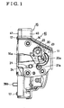
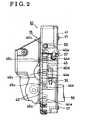
- a door lock device 10 generally includes a latch mechanism 11, open unit 12, lock unit 13 and motor 14 (actuator). These components are housed integrally in a housing 15.
- the latch mechanism 11 is arranged within a first plane surface extending in parallel with the paper space of Fig. 1 and a lock mechanism formed by the open unit 12 and the lock unit 13 and the motor 14 are arranged within a second plane extending in vertical with the first plane (vertical to the paper space).
- the housing 15 includes a housing half 40 (first housing half) covering the lock mechanism and the motor 14 portions in the right direction as viewed in Fig. 2 and further covering the latch mechanism 11 integrally in inward direction of the paper space in Fig.
- the housing half 40 (first housing half) is made of resin while the cover 41 (second housing half) is made of metal according to this embodiment.
- the material used for the housing is not limited to this embodiment.
- the shapes of the housing halves 40 and 41 are not limited to these shown in the embodiment.
- the latch mechanism 11 is explained with reference to Fig. 1.
- the latch mechanism 11 includes a latch 20 and a pawl 21.
- the latch 20 is rotatably supported by a latch shaft 22 and is provided with an engaging groove 20a.
- the groove 20a can engage with and hold a striker 23 fixed to a vehicle body (not shown) inside of the latch 20.
- the pawl 21 is rotatably supported by a pawl shaft 24 and is provided with an engaging portion 21a.
- the engaging portion 21a engages with the latch to restrict the latch from rotating in clockwise direction as viewed in Fig. 1.
- Fig. 1 shows the latched condition that the door is closed relative to the vehicle body.
- the latch 20 engages with the striker 23.
- the pawl 21 is rotated from this condition in clockwise direction to a certain amount (angle) centering the pawl shaft 24, the engaging portion 21a of the pawl is disengaged from the latch 20.
- the latch 20 is rotated by a spring (not shown) in clockwise direction.
- the engaging groove 20a is aligned with a recess 16a formed on a base member 16.
- the striker 23 can be moved away from the engaging groove 20a in the left direction as viewed in Fig. 1.
- the door becomes unlatched to be opened relative to the vehicle body. This means that the latch 20 is released from the striker 23.
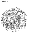
- Figs. 3 to 5 shows the door lock shown in the left side of Fig. 1.
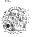
- Fig. 4 shows the condition that the cover 41 has been removed from the door lock device and
- Fig. 5 shows the condition that cap portion 45 (second case half) has been further removed from the door lock device of Fig. 4.
- the housing half 40 and the cover 41 are fixed through four pins 17.
- the fixing method is not limited to this method.
- the housing 40 is formed with a groove 40b along an upper brim 40a concaved in the left direction as viewed in Fig. 6.
- the cover 41 is formed with a flange portion 41b along an upper brim 41a projecting toward the left direction as viewed in Fig. 6.
- the groove 40b and flange portion 41b are engaged with each other when the housing half 40 and the cover 41 are assembled. Compared with the surface contact of the conventional structure, since this structure will not allow water or external objects to be introduced at the assembling portion 15a.
- the assembling portion 15a formed by the groove 40a and flange portion 41b is formed at the upper side of the housing and accordingly, even when the water is introduced from the upper side of the door lock device 10, the water will not invade into the housing 15.
- such assembling portion 15b can be formed along the entire periphery of the housing half 40 and cover 41 or may be formed at a part of the periphery other than the upper side.
- a case 42 is provided in the housing 15 and formed integrally therewith.
- the case 42 is formed such that a space 43 is provided within the housing between the upper side and right side as viewed in Fig. 4 or 5.
- the upper side means the vehicle upper side when the door lock device 10 is assembled in the door of the vehicle.
- the case 42 and the housing 15 are aligned at the lower portion, but the case 42 may be provided at the position where the space is provided at the lower side of the housing 15.
- the case 42 includes a case half 44 (first case half) and a cap portion 45 (second case half). Both cap portion 45 and the case half 44 are assembled to form the case 42.
- the case half 44 includes a reference wall 40c (first wall) commonly with the housing half 40 and is provided with a wall 44a (second wall) projecting from the reference wall 40c (first wall) toward the front direction of the paper space of Fig. 5.
- the wall 44a is of peripheral shape and has a recess 44b.
- the case half 44 is formed with a groove 44d (second groove) concaved in the left direction as viewed in Fig. 7.
- the cap portion 45 is provided with a projection 45b (second projection) projecting along the brim 45a in the left direction as viewed in Fig. 7.
- the projection 45b is engaged with the groove 44d when the cap portion 45 and the case half 44 are assembled.
- a water drain channel 66 which is communicated with the outside, is formed out side of the housing 15. In order to come water or external objects into the case, water or external objects have to get over the projection 45 and also not to discharge from the housing 15 through the drain channel 66.
- the structure of the embodiment will not allow water or external objects to be introduced into the case 42 from the assembling portion 42a of the case 42.
- Such assembling portion 42a can be formed along the entire periphery of the case half 44 and the cap portion 45, or may be formed at a part of the periphery other than the upper side.
- the assembling of the case half 44 and the cap portion 45 is made through a plurality of detent portions 44e formed on the case half 44 engage with a plurality of pawl portions 45c formed on the cap portion 45.
- the lock mechanism includes the open unit 12 and the lock unit 13.
- the open unit 12 transmits the operation force to the latch mechanism 11 from an outside handle (not shown) provided outside of the vehicle door and an inside handle (not shown) provided inside of the vehicle door (compartment side) thereby to operate the latch mechanism to be released from the engagement with the striker 23.
- the lock unit 13 transmits the locking or unlocking operation force by a locking knob (not shown) which is provided inside of door at the compartment side or the motor 14, etc.
- unlock condition means that the open unit 12 can transmit the opening operation force to the latch mechanism 11
- lock condition means that the open unit 12 can not transmit the opening operation force to the latch mechanism 11.
- the open unit 12 includes an outside open lever 31, an inside open lever 32, an open link 33 and lift lever 34.
- the outside open lever 31 is rotatably supported by the cover 41 centering the pin 31a within the housing 15 and is provided with a connection recess 31b at one end and a connecting shaft 31c at the other end.
- the connection recess 31b is connected to a cable 35, which is operatively connected to the outside handle.
- the cable 35 includes an inner cable 35a one end of which is connected to the outside handle side and the other end of which is connected to the connection recess 31b and an outer casing 35b which covers the inner cable 35a.
- an end portion 35c of the outer casing 35b is fixed to a fixed flange portion 41c of the cover 41.
- the housing half 40 includes an umbrella portion 40d (protection portion) covering the end portion 35c from the upper side. Accordingly, the end portion 35c will not be exposed to the water and prevents invasion of the water into the gap formed between the inner cable 35a and the outer casing 35b.
- the inside open lever 32 includes a first inside open lever 32a, a second inside open lever 32b and an intermediate lever 32c. These levers are supported by the cover 41 within the housing 15 and rotatable about a pin 32d relative to the cover 41.
- the first inside open lever 32a is formed with a connecting hole 32e at one end and an irregular shape hole 32f at the other end.
- the first inside open lever 32a also includes a cancel flange 32m at the left side relative to the connecting hole 32e.
- the connecting hole 32e is connected to a cable 37 associated with the inside handle.
- the cable 37 includes an inner cable 37a connected to the inside handle side at one end and connected to the connecting hole 32e at the other end and an outer casing 37b which covers the inner cable 37a.
- an end 37c of the outer casing 37b is fixed to the fixed flange portion 41d of the cover 41.
- the housing half 40 includes an umbrella portion 40e (protection portion) covering the end portion 37c from the upper side. Accordingly, the end portion 37c will not be exposed to the water and prevents invasion of the water into the gap formed between the inner cable 35a and the outer casing 37b.
- the second inside lever 32b is provided with an elongated hole 32g and an engaging end portion 32h.
- the intermediate lever 32c is provided with an elongated hole 32i, engaging projection 32j and an arc-shape hole 32k.
- the engaging projection 32j is inserted through the elongated hole 32g of the second inside lever 32b and the irregular shape hole 32f of the inside lever 32a.
- a connecting shaft 38a of a child protector lever 38 is inserted into the arc-shape hole 32k.
- the child protector lever 38 is rotatably supported by the cover 41.
- the intermediate lever 32c moves in vertical direction as viewed in Fig. 8.
- the engaging projection 32j relatively moves within the elongated hole 32g and irregular shape hole 32f relative and the pin 32d relatively moves within the elongated hole 32i.
- the open link 33 is provided with connecting elongated holes 33a and 33b at both ends, respectively and a flange 33c of approximately L shape in cross section.
- the upper side connecting elongated hole 33a is connected to the connecting shaft 31c of the outside open lever 31.
- the lock unit 13 of the lock mechanism includes a wheel gear 51 and active lever 52.
- the wheel gear 51 is of circular shape and is supported by the rotating shaft 51a and rotatable relative to the cap portion 45.
- the wheel gear 51 is housed in the case 42 provided in the housing 15.
- the wheel gear 51 is provided with gear teeth at the outer periphery thereof and is formed at the position eccentric to the rotating shaft 51a so that the projection 51b projects inward of the paper space.
- the projection 51b rotates around the rotating shaft 51a when the wheel gear 51 rotates.
- the active lever 52 includes a resin made lever 52a and metal lever 52b. These levers are rotatably supported by the cap portion 45 centering the rotation axis 52c (screw).
- the active lever 52 positions one part within the case 42 via a recess portion 44b and position the other part outside of the case 42 within the housing 15.
- the resin made lever 52a includes a recess 52g, pressing portion 52d (Fig. 5), an irregular shape hole 52e, a connecting hole 52f and an engaging portion 52m.
- the recess 52g is engaged with the projection 51b when the wheel gear 51 is rotated.
- the connecting hole 52f of the resin made lever 52a is connected to a cable 53 associated with a lock knob (not shown) provided inside of the compartment.
- a positioning spring 54 is provided and is engaged with the hole 52e at one end and engaged with a reference wall 44a at the other end.
- the engaging portion 52m projects frontward and extends outside of the case 42 from the inside via an elongated hole 45d formed on the cap portion 45.
- the metal lever 52b includes flanges 52i and 52j and boss 52k.
- the pressing portion 52d of the resin made lever 52a is in contact with the flange 52i.
- the pressing portion 52d presses upon the flange 52i so that the active lever 52 as a whole is rotatable.
- a spring 55 is provided between the resin made lever 52a and metal lever 52b.
- the spring 55 is engaged with the resin made lever 52a at one end and wound around the rotation center 52c.
- the spring 55 is engaged with the flange 52j of the metal lever 52b at the other end.
- the boss 52k of the metal lever 52b is connected to the connecting elongated hole 33b of the open link 33.
- the motor 14 is fixed to the reference wall 40c within the case 42 as shown in Fig. 5. As shown in Fig. 5, the motor 14 is connected to a connector 56 fixed to the reference wall 40c within the case via bus bar 57 (electric supply route). As shown in Fig. 3, the connector 56 can be connected from outside of the housing 15.
- the motor 14 is driven by CPU (not shown) arranged outside of the door lock device 10.
- the motor 14 includes output shaft and worm gear 14a provided on the output shaft.
- the worm gear 14a meshes with the wheel gear 51 and rotatable in both directions by motor 14.
- the motor 14 directly operates the wheel gear 51.
- the wheel gear 51 operates the active gear 52 to change the state of the door lock device 10 to locking state from unlocking state or unlocking to locking state. In other words, the motor 14 outputs the locking/unlocking operation force of the door lock device.
- the position switch 58 includes a switch piece 58a engageable with the resin made lever 52a of the active lever 52 and detects rotation position of the active lever 52. The rotation position of the active lever 52 determines the locking or unlocking state of the door lock device 10.
- the position switch 58 functions to detect the locking or unlocking state of the door lock device 10.
- the position switch 58 is connected to the connector 56 via a bus bar 59 (signal route). The state of the door lock device 10 detected by the switch 58 is transmitted to the CPU outside of the door lock device 10 via the connector 56.
- the electric parts such as motor 14, connector 56, position switch 58 and bus bars 57 and 59 are housed in the case 42 within the housing 15.
- the case 42 is structured to have a gap or clearance 43 at least at upper side of the housing 15. Accordingly, plurality of members such as the housing 15 and the case 42 cover the electric parts such as motor 14 viewing from upper side of the door lock device 10.
- the door lock device 10, particularly the case 42 has good waterproof characteristic.
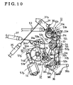
- Fig. 8 shows the door lock device positioning in unlock condition where the active lever 52 as a whole and the open link 33 are positioned at unlock position (UL).
- UL unlock position
- the open link 33 moves upward and the flange 33c of the open link 33 engages with the lift lever 34 to move the lever upward.
- This lift lever 34 is rotatably supported by the pawl shaft 24 for unitary rotation therewith.
- the lift lever moves upward, the pawl 21 is rotated in clockwise direction to have the latch mechanism 11 change from latched condition to unlatched condition.
- Fig. 9 shows the condition after the above operation has been completed.
- Fig. 11 indicates the lock position.
- the lock operation can be also achieved by, for example, the operation of the lock knob by rotation of the resin made lever 52a about the rotation center 52c via the cable 53.
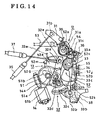
- the engaging end portion 32h of the second inside open lever 32b is upwardly engageable with the flange 33c under the condition of Fig. 14.
- the open link 33 moves upward to operate the latch mechanism 11 to unlatched position from the latched position.
- the operation will be explained hereinafter the case when the switching operation to the unlock condition by the operation of outside handle or by motor 14 from the lock condition shown in Fig. 11 is made repeatedly (this repeated operation may be made when the door system includes a so-called smart entry system).
- the smart entry system is a system wherein under the user of the vehicle (key owner) detected to be near own vehicle, when the user approaches the outside handle, the sensor such as electro-static capacitance sensor detects the needs of opening the door, the CPU drives the motor 14 to unlock the door lock device. In this case immediately before the switching to the unlock condition by the motor 14, the user may operate the outside handle.
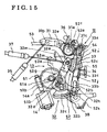
- Wheel gear 51 is rotated in clockwise direction by the actuation of the motor 14, the active lever 52 as a whole and the open link 33 are moved to the unlock position.
- the flange 33c of the open link 33 then engages with the lift lever 34.
- Fig. 15 shows the condition after the above operation has been completed.
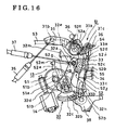
- Fig. 16 shows the condition after the above operation has been completed.
- the latch mechanism can be operated to the unlatched position.
- Figs. 17 and 18 show the second embodiment of the invention.
- the difference between the previous embodiment and the second embodiment is a difference in shape of the first inside open lever 32a of the inside open lever 32.
- the distance from the connecting hole 32e to the canceling flange 32m is shorter in the second embodiment than that of the previous embodiment.
- Fig. 17 shows the condition after the above operation has been completed.
- the second inside open lever 32b engages with and presses upward the flange 33c of the open link 33 thereby to move the open link 33 upward. Since the distance between the connecting hole 32e and the canoe ling flange 32m is shorter in this embodiment, the movement of the open link 33 toward the unlock position is retarded compared to the case of the previous embodiment. As a result, the flange 33c of the open link 33 engages with the lift lever 34 in the right direction to restrict the movement of the open link 33 toward the right direction.
- the resin made lever 52a part of the active lever 52 is rotated in counter clockwise direction about the rotation center 52c against the biasing force of the spring 55.
- Fig. 18 shows the condition after the above operation has been completed.
- the switching operation to the unlock condition and opening operation can be achieved to function as a two motion operation.
- one motion function can be changed to two motion function by minor change of shape of the inside open lever 32.
- the reference wall 40c is commonly used for the case half 44 and the housing half 40 according to the embodiments. However, such wall can be formed separately for both case half and housing half.
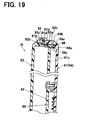
- the third embodiment will be explained base on the Fig. 19.
- the third embodiment having a different structure on the housing 15 and case 42 comparing with the first embodiment.
- the housing 15 includes a resin made housing half 61 and a resin made cover 62.
- a flange portion 61b is formed along with a verge 61a of the housing half 61.
- a groove 62b is formed on the housing half 61 along with a verge 62a of the cover 62.
- the case 42 includes a resin made case half 64 and a resin made cap portion 65.
- the case half 64 is sharing a reference wall 61c of the housing half 61 and having a wall 64a which is projecting from the reference wall 61c.
- a groove 64c is formed along with a verge 64b of a wall 64a which is formed on the case half 64.
- a projection portion 65b is formed along with a verge 65a of the cap portion 65.
- a plurality of engaging part 62c are formed on the cover 62.
- the housing half 61 and cover 62 are fastened through the locking part 61d and the engaging part 62c.
- the case half 64 and the cap portion 65 are fastened by clipping the cap portion 65 which is positioned between the verge 64b of the wall 64a and the verge 65a of the cap portion 65.
- an entering of water into the housing 15 is relatively restricted comparing with the first embodiment.
- water has to override the projection portion 65b without discharging from the housing through the drain channel 66. Consequently, an entering of water into the case 42 is relatively restricted as well as the first embodiment.
- the more entering or intrusion of water into the housing 15 is restricted, the more entering or intrusion of water into the case 42 is restricted comparing with the first embodiment.
- the actuator since the actuator is covered by the first wall, the second wall and the cap portion within the housing, the actuator becomes more waterproofed even if the door lock device should expose to the water.
- the assembling portion can more securely prevent water from entering into the housing compared to the structure of surface contact engagement in the conventional device.
- the assembling portion can more securely prevent water from entering into the case compared to the structure of surface contact engagement in the conventional device.
- the housing and the case has a first common wall integrally formed to reduce the number of parts and simplify the structure compared to the structure having separate walls of the housing and the case.
- a door lock device includes a latch mechanism engageable with or disengageable from a striker, an open unit transmitting an opening operation force to the latch mechanism for disengaging the latch mechanism from the engagement with the striker, a lock unit transmitting locking and unlocking operation forces to the open unit for operating the open unit between an unlocking condition where the opening operation force is transmittable to the latch mechanism and a locking condition where the opening operation force is not transmittable to the latch mechanism, an actuator for outputting the locking and unlocking operation forces.
- the door lock device further includes a housing for storing the latch mechanism, the open unit, the lock unit and the actuator as a unit, and a case provided within the housing for accommodating at least the actuator.
Landscapes
- Lock And Its Accessories (AREA)
Applications Claiming Priority (4)
| Application Number | Priority Date | Filing Date | Title |
|---|---|---|---|
| JP2003022298 | 2003-01-30 | ||
| JP2003022298 | 2003-01-30 | ||
| JP2004020004 | 2004-01-28 | ||
| JP2004020004A JP2004251106A (ja) | 2003-01-30 | 2004-01-28 | ドアロック装置 |
Publications (1)
| Publication Number | Publication Date |
|---|---|
| EP1445404A2 true EP1445404A2 (de) | 2004-08-11 |
Family
ID=32658603
Family Applications (1)
| Application Number | Title | Priority Date | Filing Date |
|---|---|---|---|
| EP20040002089 Withdrawn EP1445404A2 (de) | 2003-01-30 | 2004-01-30 | Türschlossvorrichtung |
Country Status (5)
| Country | Link |
|---|---|
| US (1) | US20040262927A1 (de) |
| EP (1) | EP1445404A2 (de) |
| JP (1) | JP2004251106A (de) |
| KR (1) | KR20040070062A (de) |
| CN (1) | CN1519453A (de) |
Cited By (6)
| Publication number | Priority date | Publication date | Assignee | Title |
|---|---|---|---|---|
| EP1703048A3 (de) * | 2005-02-22 | 2008-03-05 | Aisin Seiki Kabushiki Kaisha | Türverriegelungsvorrichtung für Kraftfahrzeug |
| WO2009121327A1 (de) * | 2008-03-29 | 2009-10-08 | Kiekert Aktiengesellschaft | Kraftfahrzeug-türschloss |
| FR2983227A1 (fr) * | 2011-11-30 | 2013-05-31 | Valeo Securite Habitacle | Serrure pour vehicule automobile |
| EP2562336A4 (de) * | 2010-04-22 | 2013-07-03 | Aisin Seiki | Türverriegelungsvorrichtung für fahrzeuge |
| US20230193665A1 (en) * | 2020-07-15 | 2023-06-22 | Kiekert Aktiengesellschaft | Motor vehicle lock |
| DE102022122510A1 (de) | 2022-09-06 | 2024-03-07 | Kiekert Aktiengesellschaft | Antriebsgehäuse für kraftfahrzeug-technische Anwendungen |
Families Citing this family (38)
| Publication number | Priority date | Publication date | Assignee | Title |
|---|---|---|---|---|
| US6530251B1 (en) * | 1999-11-18 | 2003-03-11 | Strattec Security Corporation | Modular vehicle door lock and latch system and method |
| US20040144142A1 (en) * | 1999-11-18 | 2004-07-29 | Strattec Security Corporation | Modular vehicle door lock and latch system and method |
| JP4650694B2 (ja) * | 2004-06-23 | 2011-03-16 | アイシン精機株式会社 | 車両用ハンドル |
| JP4321404B2 (ja) * | 2004-08-19 | 2009-08-26 | アイシン精機株式会社 | 車両用ドアロック装置 |
| AU2005307310B2 (en) * | 2004-11-16 | 2008-10-30 | Aisin Seiki Kabushiki Kaisha | Door lock apparatus for vehicles |
| JP4535856B2 (ja) | 2004-11-26 | 2010-09-01 | 三井金属鉱業株式会社 | ドア開閉装置 |
| JP2006233506A (ja) * | 2005-02-23 | 2006-09-07 | Aisin Seiki Co Ltd | ドアロック装置 |
| EP1703047B1 (de) * | 2005-02-23 | 2009-07-22 | Aisin Seiki Kabushiki Kaisha | Türschloss |
| JP4695549B2 (ja) | 2006-06-07 | 2011-06-08 | 三井金属アクト株式会社 | ドア開閉装置 |
| JP4856504B2 (ja) * | 2006-09-11 | 2012-01-18 | 三井金属アクト株式会社 | アクチュエータユニット |
| JP4503051B2 (ja) * | 2007-07-23 | 2010-07-14 | 三井金属鉱業株式会社 | ドアロック装置 |
| JP5092175B2 (ja) * | 2007-08-13 | 2012-12-05 | 三井金属アクト株式会社 | ドアロック装置 |
| JP4775345B2 (ja) * | 2007-08-24 | 2011-09-21 | アイシン精機株式会社 | 車両用ドアロック装置 |
| JP2009185539A (ja) * | 2008-02-07 | 2009-08-20 | Yuhshin Co Ltd | カバー組付構造 |
| JP5103224B2 (ja) * | 2008-02-28 | 2012-12-19 | 株式会社ユーシン | ドアロック装置 |
| WO2010122887A1 (ja) * | 2009-04-23 | 2010-10-28 | アイシン精機株式会社 | 車両用ドアロック装置 |
| JP5310474B2 (ja) * | 2009-10-16 | 2013-10-09 | アイシン精機株式会社 | ダブルロック式車両用ドアロック装置 |
| JP5421083B2 (ja) * | 2009-11-27 | 2014-02-19 | 株式会社ユーシン | ドアロック装置 |
| JP5170132B2 (ja) * | 2010-03-15 | 2013-03-27 | アイシン精機株式会社 | チャイルドロック機構 |
| JP5293674B2 (ja) * | 2010-04-22 | 2013-09-18 | アイシン精機株式会社 | 車両用ドアロック装置 |
| KR20120000913A (ko) * | 2010-06-28 | 2012-01-04 | 현대자동차주식회사 | 슬라이딩 도어의 록킹 컨트롤러 구조 |
| US8456180B2 (en) * | 2010-08-10 | 2013-06-04 | Toyota Motor Engineering & Manufacturing North America, Inc. | Capacitive switch reference method |
| JP5721511B2 (ja) * | 2011-04-14 | 2015-05-20 | 株式会社ユーシン | ドアロック装置 |
| JP5875366B2 (ja) * | 2011-12-28 | 2016-03-02 | アイシン機工株式会社 | ドアロック装置のバスバー構造 |
| EP2653639B1 (de) * | 2012-04-17 | 2014-09-24 | Magna Closures SpA | Elektrisches Fahrzeugsschloss |
| US9284758B2 (en) * | 2012-06-28 | 2016-03-15 | Mitsui Kinzoku Act Corporation | Operating device for a vehicle door latch |
| JP6080518B2 (ja) * | 2012-11-27 | 2017-02-15 | 株式会社ユーシン | ドアロック装置 |
| DE102013106672A1 (de) * | 2013-03-01 | 2014-09-04 | Kiekert Aktiengesellschaft | Kraftfahrzeugtürverschluss |
| JP6303768B2 (ja) * | 2014-04-24 | 2018-04-04 | アイシン精機株式会社 | 車両用ドアロック装置 |
| JP6308031B2 (ja) * | 2014-06-03 | 2018-04-11 | アイシン精機株式会社 | 車両用ドアロック装置 |
| JP6364650B2 (ja) * | 2014-08-05 | 2018-08-01 | 三井金属アクト株式会社 | ドアラッチ用アクチュエータ |
| DE102016109556A1 (de) * | 2015-05-26 | 2016-12-01 | Inteva Products, Llc | Gehäuse für ein Schloss mit Wasserablauföffnung und Verfahren zum Ableiten von Wasser aus einem Schloss |
| DE102015108738A1 (de) * | 2015-06-02 | 2016-12-08 | Kiekert Ag | Kraftfahrzeugtürverschluss |
| DE102015108739A1 (de) * | 2015-06-02 | 2016-12-08 | Kiekert Ag | Verfahren zur Steuerung eines Kraftfahrzeugtürverschlusses |
| JP6528207B2 (ja) * | 2015-07-31 | 2019-06-12 | 三井金属アクト株式会社 | ドアロック装置の組立方法およびドアロック装置 |
| JP6649052B2 (ja) * | 2015-11-18 | 2020-02-19 | 株式会社ユーシン | ドアロック装置 |
| JP6762242B2 (ja) * | 2017-01-30 | 2020-09-30 | ジーコム コーポレイションGecom Corporation | 車両用ドアラッチ装置 |
| US20200165843A1 (en) * | 2018-11-28 | 2020-05-28 | Magna Closures Inc. | Vehicular latch assembly with snap-type connection feature providing an integrated sealing function |
Family Cites Families (5)
| Publication number | Priority date | Publication date | Assignee | Title |
|---|---|---|---|---|
| CA1326502C (en) * | 1988-03-11 | 1994-01-25 | Wolfgang Thau | Latch mechanism, components thereof and process of manufacture for components thereof |
| GB9108447D0 (en) * | 1991-04-19 | 1991-06-05 | Rockwell Automotive Body Syst | Vehicle door latches |
| US6463773B1 (en) * | 1999-03-05 | 2002-10-15 | Strattec Security Corporation | Electronic latch apparatus and method |
| US6328353B1 (en) * | 1999-06-16 | 2001-12-11 | Atoma International | Vehicle door latch assembly |
| JP2001173290A (ja) * | 1999-12-21 | 2001-06-26 | Mitsui Mining & Smelting Co Ltd | アクチュエータユニット |
-
2004
- 2004-01-28 JP JP2004020004A patent/JP2004251106A/ja active Pending
- 2004-01-29 KR KR1020040005792A patent/KR20040070062A/ko not_active Ceased
- 2004-01-30 CN CNA200410002572XA patent/CN1519453A/zh active Pending
- 2004-01-30 EP EP20040002089 patent/EP1445404A2/de not_active Withdrawn
- 2004-01-30 US US10/767,271 patent/US20040262927A1/en not_active Abandoned
Cited By (9)
| Publication number | Priority date | Publication date | Assignee | Title |
|---|---|---|---|---|
| EP1703048A3 (de) * | 2005-02-22 | 2008-03-05 | Aisin Seiki Kabushiki Kaisha | Türverriegelungsvorrichtung für Kraftfahrzeug |
| US7380845B2 (en) | 2005-02-22 | 2008-06-03 | Aisin Seiki Kabushiki Kaisha | Vehicle door lock device |
| WO2009121327A1 (de) * | 2008-03-29 | 2009-10-08 | Kiekert Aktiengesellschaft | Kraftfahrzeug-türschloss |
| EP2562336A4 (de) * | 2010-04-22 | 2013-07-03 | Aisin Seiki | Türverriegelungsvorrichtung für fahrzeuge |
| FR2983227A1 (fr) * | 2011-11-30 | 2013-05-31 | Valeo Securite Habitacle | Serrure pour vehicule automobile |
| WO2013079639A1 (fr) * | 2011-11-30 | 2013-06-06 | Valeo Securite Habitacle | Serrure pour vehicule automobile |
| US20230193665A1 (en) * | 2020-07-15 | 2023-06-22 | Kiekert Aktiengesellschaft | Motor vehicle lock |
| US12291898B2 (en) * | 2020-07-15 | 2025-05-06 | Kiekert Ag | Motor vehicle lock |
| DE102022122510A1 (de) | 2022-09-06 | 2024-03-07 | Kiekert Aktiengesellschaft | Antriebsgehäuse für kraftfahrzeug-technische Anwendungen |
Also Published As
| Publication number | Publication date |
|---|---|
| CN1519453A (zh) | 2004-08-11 |
| US20040262927A1 (en) | 2004-12-30 |
| JP2004251106A (ja) | 2004-09-09 |
| KR20040070062A (ko) | 2004-08-06 |
Similar Documents
| Publication | Publication Date | Title |
|---|---|---|
| EP1445404A2 (de) | Türschlossvorrichtung | |
| JP4418319B2 (ja) | 自動車用ドアラッチ装置 | |
| US20090236863A1 (en) | Electric door latch apparatus | |
| US7232161B2 (en) | Latch device for vehicle tailgate | |
| US7703310B2 (en) | Door opening and closing device for vehicle and assembly method thereof | |
| US6679532B2 (en) | Vehicle door latch device | |
| EP2703581B1 (de) | Türverriegelungsvorrichtung | |
| CN101545342B (zh) | 门锁装置 | |
| JP5310435B2 (ja) | テールゲート用オープンスイッチ誤操作防止構造 | |
| EP1703047B1 (de) | Türschloss | |
| US6428059B2 (en) | Latch detector for automotive door locks | |
| EP1447501B1 (de) | Türschloss | |
| EP1726754B1 (de) | Türverriegelungseinrichtung für ein Fahrzeug | |
| US6375234B1 (en) | Motor-vehicle door latch with sealed housing | |
| CN114080484B (zh) | 机动车门锁 | |
| US20090212577A1 (en) | Vehicle door lock device | |
| JP6592842B2 (ja) | 車両用ドアロック装置 | |
| JP5310474B2 (ja) | ダブルロック式車両用ドアロック装置 | |
| JPH0797881A (ja) | 車両用ドアロツク装置 | |
| GB2458574A (en) | Door lock having a double lock for disabling a double action mechanism wherein a lock is normally switched to an unlocked position by using an inside handle | |
| JP4373833B2 (ja) | ドアロック装置 | |
| JP7749897B2 (ja) | ドアラッチ装置の防水構造 | |
| JP7175181B2 (ja) | ドアラッチ装置 | |
| JP2002106226A (ja) | 車両用トランク | |
| CN211500188U (zh) | 车辆用门锁装置 |
Legal Events
| Date | Code | Title | Description |
|---|---|---|---|
| PUAI | Public reference made under article 153(3) epc to a published international application that has entered the european phase |
Free format text: ORIGINAL CODE: 0009012 |
|
| AK | Designated contracting states |
Kind code of ref document: A2 Designated state(s): AT BE BG CH CY CZ DE DK EE ES FI FR GB GR HU IE IT LI LU MC NL PT RO SE SI SK TR |
|
| AX | Request for extension of the european patent |
Extension state: AL LT LV MK |
|
| RIN1 | Information on inventor provided before grant (corrected) |
Inventor name: TANABE, SHIGERU Inventor name: NISHIO, TAKASHI Inventor name: KUNIMATSU, YUKINOBU Inventor name: MURAMATSU, AKIRA Inventor name: OYA, SHIGEHIRO Inventor name: SUZUMURA, MAKOTO Inventor name: FUKUNAGA, KATSUTOSHI |
|
| RIN1 | Information on inventor provided before grant (corrected) |
Inventor name: TANABE, SHIGERU Inventor name: NISHIO, TAKASHI Inventor name: KUNIMATSU, YUKINOBU Inventor name: MURAMATSU, AKIRA Inventor name: OYA, SHIGEHIRO Inventor name: SUZUMURA, MAKOTO Inventor name: FUKUNAGA, KATSUTOSHI |
|
| STAA | Information on the status of an ep patent application or granted ep patent |
Free format text: STATUS: THE APPLICATION IS DEEMED TO BE WITHDRAWN |
|
| 18D | Application deemed to be withdrawn |
Effective date: 20070801 |