EP1443210A2 - Motorpumpenaggregat - Google Patents
Motorpumpenaggregat Download PDFInfo
- Publication number
- EP1443210A2 EP1443210A2 EP03022470A EP03022470A EP1443210A2 EP 1443210 A2 EP1443210 A2 EP 1443210A2 EP 03022470 A EP03022470 A EP 03022470A EP 03022470 A EP03022470 A EP 03022470A EP 1443210 A2 EP1443210 A2 EP 1443210A2
- Authority
- EP
- European Patent Office
- Prior art keywords
- pumps
- pump
- motor
- electric motor
- rotor
- Prior art date
- Legal status (The legal status is an assumption and is not a legal conclusion. Google has not performed a legal analysis and makes no representation as to the accuracy of the status listed.)
- Granted
Links
Images
Classifications
-
- F—MECHANICAL ENGINEERING; LIGHTING; HEATING; WEAPONS; BLASTING
- F04—POSITIVE - DISPLACEMENT MACHINES FOR LIQUIDS; PUMPS FOR LIQUIDS OR ELASTIC FLUIDS
- F04C—ROTARY-PISTON, OR OSCILLATING-PISTON, POSITIVE-DISPLACEMENT MACHINES FOR LIQUIDS; ROTARY-PISTON, OR OSCILLATING-PISTON, POSITIVE-DISPLACEMENT PUMPS
- F04C11/00—Combinations of two or more machines or pumps, each being of rotary-piston or oscillating-piston type; Pumping installations
- F04C11/001—Combinations of two or more machines or pumps, each being of rotary-piston or oscillating-piston type; Pumping installations of similar working principle
-
- A—HUMAN NECESSITIES
- A61—MEDICAL OR VETERINARY SCIENCE; HYGIENE
- A61J—CONTAINERS SPECIALLY ADAPTED FOR MEDICAL OR PHARMACEUTICAL PURPOSES; DEVICES OR METHODS SPECIALLY ADAPTED FOR BRINGING PHARMACEUTICAL PRODUCTS INTO PARTICULAR PHYSICAL OR ADMINISTERING FORMS; DEVICES FOR ADMINISTERING FOOD OR MEDICINES ORALLY; BABY COMFORTERS; DEVICES FOR RECEIVING SPITTLE
- A61J1/00—Containers specially adapted for medical or pharmaceutical purposes
- A61J1/03—Containers specially adapted for medical or pharmaceutical purposes for pills or tablets
-
- F—MECHANICAL ENGINEERING; LIGHTING; HEATING; WEAPONS; BLASTING
- F04—POSITIVE - DISPLACEMENT MACHINES FOR LIQUIDS; PUMPS FOR LIQUIDS OR ELASTIC FLUIDS
- F04C—ROTARY-PISTON, OR OSCILLATING-PISTON, POSITIVE-DISPLACEMENT MACHINES FOR LIQUIDS; ROTARY-PISTON, OR OSCILLATING-PISTON, POSITIVE-DISPLACEMENT PUMPS
- F04C15/00—Component parts, details or accessories of machines, pumps or pumping installations, not provided for in groups F04C2/00 - F04C14/00
- F04C15/0057—Driving elements, brakes, couplings, transmission specially adapted for machines or pumps
- F04C15/008—Prime movers
Definitions
- the invention relates to a motor pump unit comprising an electric motor and a pump.
- the motor and pump are interleaved; the Motor envelops the pump.
- EP 0 611 887 A1 describes a further motor pump unit.
- the rotor of the motor is an independent component, but with the cylinder block a piston pump rotatably connected.
- Units of this type have the great advantage that they only have one occupy minimal space. But there is still room for improvement.
- the invention has for its object a motor pump unit mentioned design to improve even further, especially with regard to the Manufacturing effort and space requirements.
- the invention is based on the aforementioned WO document, but with one Multiplication of the individual units.
- a preferred Embodiment comprises the entire motor pump unit two axially internal gear pumps aligned with one another and an electric motor which which is assigned to one of the two pumps. They are each other neighboring pumps are assigned to each other in such a way that they single electric motor can be driven. It gets involved with it achieve high delivery volume and / or high delivery pressure.
- a large The advantage is that the two pumps are within a single housing are arranged so that when operating the entire aggregate of oil are enclosed and therefore no seals are required.
- the two pumps can be completely identical. But you can too have different diameters in the conveying area, i.e. where the Conveyor tooth limit.
- Asynchronous motors for example Asynchronous motors, reluctance motors or so-called squirrel-cage rotors.
- the invention can be used particularly advantageously in the case of internal gear pumps apply.
- the pump forms a completely independent, self-sufficient unit. It can be Manufacture separately, check separately and completely in the stator of the Install the electric motor enclosed space.
- the engine is cooled with oil.
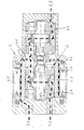
- the motor pump unit comprises an electric motor 1 with a Stator laminated core 1.1, a winding 1.2 and a rotor 1.3.
- first internal gear pump 2 This has a pinion 2.1 on, a compared to this eccentric ring gear 2.2 and a pinion shaft 2.3.
- the pinion shaft 2.3 is mounted in side windows 2.4, 2.5.
- the two elements, motor and first pump, are common Enclosed housing 3.
- housing 3 In the housing 3 there is an inlet 3.1 and a first outlet 3.2 for the medium to be pumped.
- the rotor 1.3 of the motor 1 is pot-shaped. In the present axial section it appears U-shaped.
- the pinion shaft 2.3 projects with the rotor 1.3 a toothing 2.3.1 in rotary connection.
- web 1.3.1 of the U is namely an internal toothing, while the pinion shaft a corresponding Has external teeth. Comb the internal teeth and external teeth together.
- the rotor 1.3 is mounted on the first pump 2, more precisely on the Ring gear 2.3 and the side windows 2.4, 2.5.
- a second internal gear pump is provided. This is arranged axially next to the first pump 2, in such a way that the The axes of the two pumps are aligned.
- the housing 3 is over the led out first pump 2 and flows around the second pump 20th
- the second pump 20 is identical in construction to the first pump 2. It has accordingly also a pinion shaft 20.3, which with the pinion shaft 2.3 is structurally identical and which also has a toothing 20.3.1 with the rotor 1.3 is in rotary connection.
- the housing 3 has a second outlet 3.3.
- the second pump 20 is fixed on the right cover of the housing 3.
- the cup-shaped rotor thus drives 1.3 the two pinion shafts 2.3, 20.3.
- the course of the oil is shown by the bold arrows.
- the oil will at inlet 3.1, shown in the figure on the left, sucked in, passes through the gap between the stator laminated core 1.1 and the rotor 1.3 in the space between the two pumps 2 and 20.
- the oil flow divides there.
- a partial flow occurs through the pump 2 and at the first outlet 3.2 again, and on second partial flow passes through the second pump 20 and on the second Spout 3.2 out.
- the motor pump unit thus has a suction connection and two pressure connections.
Landscapes
- Engineering & Computer Science (AREA)
- Health & Medical Sciences (AREA)
- General Engineering & Computer Science (AREA)
- Mechanical Engineering (AREA)
- General Health & Medical Sciences (AREA)
- Public Health (AREA)
- Veterinary Medicine (AREA)
- Animal Behavior & Ethology (AREA)
- Life Sciences & Earth Sciences (AREA)
- Pharmacology & Pharmacy (AREA)
- Rotary Pumps (AREA)
- Details And Applications Of Rotary Liquid Pumps (AREA)
- Control Of Electric Motors In General (AREA)
- Compressor (AREA)
- Reciprocating Pumps (AREA)
- Connection Of Motors, Electrical Generators, Mechanical Devices, And The Like (AREA)
Abstract
Description
Claims (1)
- Motorpumpenaggregat;1.1 mit zwei Innenzahnradpumpen (2,20), jeweils umfassend ein Ritzel, ein gegenüber diesem exzentrisches Hohlrad sowie eine Ritzelwelle, die in Seitenscheiben gelagert ist;1.2 die Ritzel der beiden Pumpen (2, 20) sind baugleich, und die Achsen der Pumpen (2, 20) fluchten miteinander;1.3 wenigstens einem der beiden Pumpen (2, 20) ist ein Elektromotor (1) zugeordnet;1.4 der Rotor (1.3) des Elektromotors (1) ist - im Axialschnitt gesehen - U-förmig und umschließt die ihm zugeordnete Pumpe konzentrisch;1.5 der Steg (1.3.1) des U ist im Bereich der Drehachse mit einer Innenverzahnung versehen;1.6 die Innenverzahnung des Steges kämmt mit den beiden Ritzeln;1.7 der Elektromotor (1) und die Pumpen (2, 20) sind von einem einzigen Gehäuse (3) umschlossen;1.8 den beiden Pumpen (2, 20) sind ein einziger Sauganschluss (3.1) und zwei Druckanschlüsse (3.2, 3.3) zugeordnet.
Applications Claiming Priority (2)
| Application Number | Priority Date | Filing Date | Title |
|---|---|---|---|
| DE10304121 | 2003-01-31 | ||
| DE10304121A DE10304121A1 (de) | 2003-01-31 | 2003-01-31 | Motorpumpenaggregat |
Publications (4)
| Publication Number | Publication Date |
|---|---|
| EP1443210A2 true EP1443210A2 (de) | 2004-08-04 |
| EP1443210A3 EP1443210A3 (de) | 2005-08-10 |
| EP1443210B1 EP1443210B1 (de) | 2006-08-02 |
| EP1443210B8 EP1443210B8 (de) | 2006-09-06 |
Family
ID=32603100
Family Applications (1)
| Application Number | Title | Priority Date | Filing Date |
|---|---|---|---|
| EP03022470A Expired - Lifetime EP1443210B8 (de) | 2003-01-31 | 2003-10-08 | Motorpumpenaggregat |
Country Status (6)
| Country | Link |
|---|---|
| US (1) | US7381036B2 (de) |
| EP (1) | EP1443210B8 (de) |
| JP (1) | JP3971369B2 (de) |
| KR (1) | KR20040069989A (de) |
| AT (1) | ATE335132T1 (de) |
| DE (2) | DE10304121A1 (de) |
Cited By (4)
| Publication number | Priority date | Publication date | Assignee | Title |
|---|---|---|---|---|
| WO2008028546A1 (de) * | 2006-09-08 | 2008-03-13 | Voith Turbo Gmbh & Co. Kg | Hydrostatische energieerzeugungseinheit |
| EP2924291A3 (de) * | 2014-02-25 | 2015-10-14 | LG Innotek Co., Ltd. | Elektrische pumpe |
| CN105464964A (zh) * | 2015-12-31 | 2016-04-06 | 太仓顺达磁力泵科技有限公司 | 一种用于固液混合物料输送的传输泵 |
| EP4575229A1 (de) * | 2023-12-19 | 2025-06-25 | Rolls-Royce plc | Verdrängerpumpensystem |
Families Citing this family (16)
| Publication number | Priority date | Publication date | Assignee | Title |
|---|---|---|---|---|
| JP2005273648A (ja) * | 2004-02-23 | 2005-10-06 | Aisin Seiki Co Ltd | 電動ポンプ |
| DE202005005620U1 (de) * | 2005-04-08 | 2006-08-17 | Hawe Hydraulik Gmbh & Co. Kg | Pumpenaggregat |
| FR2918718B1 (fr) * | 2007-07-10 | 2013-06-28 | Inergy Automotive Systems Res | Pompe rotative pour vehicule. |
| JP2009191754A (ja) * | 2008-02-15 | 2009-08-27 | Toyota Industries Corp | 可変容量ギヤポンプ |
| JP5860695B2 (ja) * | 2011-12-28 | 2016-02-16 | Kyb株式会社 | 電動オイルポンプ |
| JP5934543B2 (ja) * | 2012-03-29 | 2016-06-15 | Kyb株式会社 | 流体圧駆動ユニット |
| JP5767996B2 (ja) * | 2012-03-29 | 2015-08-26 | カヤバ工業株式会社 | 流体圧駆動ユニット |
| DE102015015863A1 (de) * | 2015-12-09 | 2017-06-14 | Fte Automotive Gmbh | Elektromotorisch angetriebene Flüssigkeitspumpe |
| JPWO2018062107A1 (ja) * | 2016-09-30 | 2019-10-10 | 日本電産トーソク株式会社 | ポンプ装置 |
| DE102016225923B4 (de) | 2016-12-21 | 2020-06-18 | Hawe Hydraulik Se | Pumpenaggregat für ein Hydrauliksystem und Kanalelement für ein Pumpenaggregat |
| DE102019200560B4 (de) | 2018-09-14 | 2025-04-30 | Hanon Systems Efp Deutschland Gmbh | Gerotorpumpe und Verfahren zur Herstellung eines Druckausgleichs in einer Gerotorpumpe |
| CN113167271B (zh) * | 2018-11-13 | 2024-03-15 | Ghsp公司 | 用于多种应用的模块化流体泵 |
| CN112112796A (zh) | 2019-06-19 | 2020-12-22 | 杭州三花研究院有限公司 | 电动泵 |
| CN111102202A (zh) * | 2019-12-21 | 2020-05-05 | 郭伟聪 | 一种多方位液体远距离输送装置 |
| US11990819B2 (en) * | 2020-11-24 | 2024-05-21 | Bosch Rexroth Corporation | Electric and hydraulic machine |
| DE102023116639A1 (de) * | 2023-06-23 | 2024-12-24 | Valeo Embrayages | Hydraulikpumpe |
Family Cites Families (18)
| Publication number | Priority date | Publication date | Assignee | Title |
|---|---|---|---|---|
| US2420124A (en) * | 1944-11-27 | 1947-05-06 | Coulson Charles Chilton | Motor-compressor unit |
| US2691346A (en) * | 1948-09-07 | 1954-10-12 | F E Myers & Bro Co | Double rotary fluid pump |
| US2711286A (en) * | 1952-08-01 | 1955-06-21 | Wetmore Hodges | Motor-pump or compressor |
| US2871793A (en) * | 1956-06-29 | 1959-02-03 | Robbins & Myers | Electric motor and pump combination |
| FR1458497A (fr) * | 1965-09-23 | 1966-03-04 | Outil Hydraulique B G | Répartiteur-synchronisateur de débits |
| DE2938276A1 (de) * | 1979-09-21 | 1981-04-09 | Robert Bosch Gmbh, 7000 Stuttgart | Fluegelzellenverdichter |
| AU595039B2 (en) * | 1986-04-23 | 1990-03-22 | A.B. Svenska Rotor Maskiner | Cone type screw compressor |
| DE3614819A1 (de) * | 1986-05-02 | 1987-11-12 | Kloeckner Humboldt Deutz Ag | Innenverzahnte doppelpumpe mit gemeinsamer ansaugung und getrennten druckausgaengen |
| JP2687822B2 (ja) | 1992-08-06 | 1997-12-08 | ダイキン工業株式会社 | 流体圧力発生装置 |
| EP0769621A1 (de) * | 1995-09-26 | 1997-04-23 | Fraunhofer-Gesellschaft Zur Förderung Der Angewandten Forschung E.V. | Mikropumpe und Mikromotor |
| DE19538278A1 (de) | 1995-10-15 | 1996-05-02 | Sbs Sondermaschinen Gmbh | Umwälzpumpe mit Elektroantrieb |
| US5857842A (en) * | 1997-06-16 | 1999-01-12 | Sheehan; Kevin | Seamless pump with coaxial magnetic coupling including stator and rotor |
| DE19817162A1 (de) * | 1998-04-17 | 1999-10-21 | Sachsenhydraulik Gmbh | Elektrohydraulischer Kompaktantrieb |
| US6499966B1 (en) * | 1998-08-06 | 2002-12-31 | Automative Motion Technology, Ltd. | Motor driven pump |
| DE10015139A1 (de) * | 2000-03-29 | 2001-10-11 | Voith Turbo Kg | Motorpumpenaggregat |
| US6733249B2 (en) * | 2001-05-17 | 2004-05-11 | Delphi Technologies, Inc. | Multi-stage internal gear fuel pump |
| US6699024B2 (en) * | 2001-06-29 | 2004-03-02 | Parker Hannifin Corporation | Hydraulic motor |
| KR100875749B1 (ko) * | 2002-07-02 | 2008-12-24 | 엘지전자 주식회사 | 밀폐형 압축기 |
-
2003
- 2003-01-31 DE DE10304121A patent/DE10304121A1/de not_active Ceased
- 2003-10-08 AT AT03022470T patent/ATE335132T1/de not_active IP Right Cessation
- 2003-10-08 EP EP03022470A patent/EP1443210B8/de not_active Expired - Lifetime
- 2003-10-08 DE DE50304454T patent/DE50304454D1/de not_active Expired - Lifetime
- 2003-11-26 JP JP2003396239A patent/JP3971369B2/ja not_active Expired - Fee Related
-
2004
- 2004-01-15 KR KR1020040002837A patent/KR20040069989A/ko not_active Withdrawn
- 2004-01-30 US US10/768,495 patent/US7381036B2/en not_active Expired - Fee Related
Cited By (7)
| Publication number | Priority date | Publication date | Assignee | Title |
|---|---|---|---|---|
| WO2008028546A1 (de) * | 2006-09-08 | 2008-03-13 | Voith Turbo Gmbh & Co. Kg | Hydrostatische energieerzeugungseinheit |
| KR20090074028A (ko) * | 2006-09-08 | 2009-07-03 | 보이트 터보 게엠베하 운트 콤파니 카게 | 유체정역학적 전력 생성 장치 |
| US8143754B2 (en) | 2006-09-08 | 2012-03-27 | Voith Turbo Gmbh & Co. Kg | Hydrostatic energy generation unit |
| EP2924291A3 (de) * | 2014-02-25 | 2015-10-14 | LG Innotek Co., Ltd. | Elektrische pumpe |
| US10190584B2 (en) | 2014-02-25 | 2019-01-29 | Lg Innotek Co., Ltd. | Electric pump |
| CN105464964A (zh) * | 2015-12-31 | 2016-04-06 | 太仓顺达磁力泵科技有限公司 | 一种用于固液混合物料输送的传输泵 |
| EP4575229A1 (de) * | 2023-12-19 | 2025-06-25 | Rolls-Royce plc | Verdrängerpumpensystem |
Also Published As
| Publication number | Publication date |
|---|---|
| EP1443210A3 (de) | 2005-08-10 |
| US20040219035A1 (en) | 2004-11-04 |
| EP1443210B1 (de) | 2006-08-02 |
| DE10304121A1 (de) | 2004-08-12 |
| KR20040069989A (ko) | 2004-08-06 |
| ATE335132T1 (de) | 2006-08-15 |
| US7381036B2 (en) | 2008-06-03 |
| EP1443210B8 (de) | 2006-09-06 |
| JP2004232627A (ja) | 2004-08-19 |
| JP3971369B2 (ja) | 2007-09-05 |
| DE50304454D1 (de) | 2006-09-14 |
Similar Documents
| Publication | Publication Date | Title |
|---|---|---|
| EP1181453B1 (de) | Motorpumpenaggregat | |
| EP1443210B1 (de) | Motorpumpenaggregat | |
| EP2122174B1 (de) | Integrierte innenzahnradpumpeneinheit mit elektrischem motor | |
| CH669979A5 (de) | ||
| EP2473740A1 (de) | Zweistufige kreiselpumpe | |
| EP1536139B1 (de) | Pumpenaggregat mit einer Zahnradpumpe und einem Elektromotor | |
| DE3202993C2 (de) | Drehkolbenverdichter | |
| DE3407081C2 (de) | ||
| EP1526282B1 (de) | Motorpumpenaggregat | |
| EP1413757A2 (de) | Motorpumpenaggregat | |
| DE20305937U1 (de) | Pumpe mit integriertem Hydraulik-Motor | |
| DE102022206319A1 (de) | Elektrische Zahnradpumpe für ein Kraftfahrzeug, insbesondere Gerotor-Pumpe sowie Set aus mehreren Zahnradpumpen | |
| EP1777411A1 (de) | Motor-Pumpen-Aggregat | |
| WO2023174888A1 (de) | Ölpumpe für ein kraftfahrzeug | |
| DE4038704C2 (de) | Drehkolbenpumpe | |
| WO2006120138A1 (de) | Innenzahnrad-kraftstoffpump | |
| DE102010063517A1 (de) | Pumpe, Verdichter oder Motor mehrstufig oder mehrflutig | |
| EP1989448A1 (de) | Ölpumpen- und vakuumpumpenmodul | |
| DE102005029967A1 (de) | Pumpvorrichtung für ein Doppelkupplungsgetriebe eines Kraftfahrzeuges | |
| DE19980647B4 (de) | Spiralverdichter mit einem exzentrischen Kurbelmechanismus, der eine verlängerte Welle umfasst | |
| WO2026027324A1 (de) | Elektrische verdrängerpumpe sowie öldurchströmungskreislauf in der elektrischen verdrängerpumpe | |
| DE4234055A1 (de) | Spiralenkompressor | |
| DE102024110150A1 (de) | Fluidpumpe | |
| EP1030963A1 (de) | Saugrohr mit einlegekomponente | |
| DE9018104U1 (de) | Drehkolbenpumpe |
Legal Events
| Date | Code | Title | Description |
|---|---|---|---|
| PUAI | Public reference made under article 153(3) epc to a published international application that has entered the european phase |
Free format text: ORIGINAL CODE: 0009012 |
|
| AK | Designated contracting states |
Kind code of ref document: A2 Designated state(s): AT BE BG CH CY CZ DE DK EE ES FI FR GB GR HU IE IT LI LU MC NL PT RO SE SI SK TR |
|
| AX | Request for extension of the european patent |
Extension state: AL LT LV MK |
|
| PUAL | Search report despatched |
Free format text: ORIGINAL CODE: 0009013 |
|
| AK | Designated contracting states |
Kind code of ref document: A3 Designated state(s): AT BE BG CH CY CZ DE DK EE ES FI FR GB GR HU IE IT LI LU MC NL PT RO SE SI SK TR |
|
| AX | Request for extension of the european patent |
Extension state: AL LT LV MK |
|
| RIC1 | Information provided on ipc code assigned before grant |
Ipc: 7F 04C 15/00 B Ipc: 7F 04C 2/10 B Ipc: 7F 04C 11/00 A |
|
| 17P | Request for examination filed |
Effective date: 20050803 |
|
| GRAP | Despatch of communication of intention to grant a patent |
Free format text: ORIGINAL CODE: EPIDOSNIGR1 |
|
| AKX | Designation fees paid |
Designated state(s): AT BE BG CH CY CZ DE DK EE ES FI FR GB GR HU IE IT LI LU MC NL PT RO SE SI SK TR |
|
| GRAS | Grant fee paid |
Free format text: ORIGINAL CODE: EPIDOSNIGR3 |
|
| GRAA | (expected) grant |
Free format text: ORIGINAL CODE: 0009210 |
|
| AK | Designated contracting states |
Kind code of ref document: B1 Designated state(s): AT BE BG CH CY CZ DE DK EE ES FI FR GB GR HU IE IT LI LU MC NL PT RO SE SI SK TR |
|
| PG25 | Lapsed in a contracting state [announced via postgrant information from national office to epo] |
Ref country code: IT Free format text: LAPSE BECAUSE OF FAILURE TO SUBMIT A TRANSLATION OF THE DESCRIPTION OR TO PAY THE FEE WITHIN THE PRESCRIBED TIME-LIMIT;WARNING: LAPSES OF ITALIAN PATENTS WITH EFFECTIVE DATE BEFORE 2007 MAY HAVE OCCURRED AT ANY TIME BEFORE 2007. THE CORRECT EFFECTIVE DATE MAY BE DIFFERENT FROM THE ONE RECORDED. Effective date: 20060802 Ref country code: SK Free format text: LAPSE BECAUSE OF FAILURE TO SUBMIT A TRANSLATION OF THE DESCRIPTION OR TO PAY THE FEE WITHIN THE PRESCRIBED TIME-LIMIT Effective date: 20060802 Ref country code: FI Free format text: LAPSE BECAUSE OF FAILURE TO SUBMIT A TRANSLATION OF THE DESCRIPTION OR TO PAY THE FEE WITHIN THE PRESCRIBED TIME-LIMIT Effective date: 20060802 Ref country code: CZ Free format text: LAPSE BECAUSE OF FAILURE TO SUBMIT A TRANSLATION OF THE DESCRIPTION OR TO PAY THE FEE WITHIN THE PRESCRIBED TIME-LIMIT Effective date: 20060802 Ref country code: SI Free format text: LAPSE BECAUSE OF FAILURE TO SUBMIT A TRANSLATION OF THE DESCRIPTION OR TO PAY THE FEE WITHIN THE PRESCRIBED TIME-LIMIT Effective date: 20060802 Ref country code: IE Free format text: LAPSE BECAUSE OF FAILURE TO SUBMIT A TRANSLATION OF THE DESCRIPTION OR TO PAY THE FEE WITHIN THE PRESCRIBED TIME-LIMIT Effective date: 20060802 Ref country code: RO Free format text: LAPSE BECAUSE OF FAILURE TO SUBMIT A TRANSLATION OF THE DESCRIPTION OR TO PAY THE FEE WITHIN THE PRESCRIBED TIME-LIMIT Effective date: 20060802 Ref country code: NL Free format text: LAPSE BECAUSE OF FAILURE TO SUBMIT A TRANSLATION OF THE DESCRIPTION OR TO PAY THE FEE WITHIN THE PRESCRIBED TIME-LIMIT Effective date: 20060802 |
|
| REG | Reference to a national code |
Ref country code: GB Ref legal event code: FG4D Free format text: NOT ENGLISH |
|
| RAP2 | Party data changed (patent owner data changed or rights of a patent transferred) |
Owner name: VOITH TURBO GMBH & CO. KG |
|
| REG | Reference to a national code |
Ref country code: GB Ref legal event code: ERR Free format text: NOTIFICATION HAS NOW BEEN RECEIVED FROM THE EUROPEAN PATENT OFFICE THAT THE CORRECT NAME IS: VOITH TURBO GMBH & CO KG THIS CORRECTION WILL BE PUBLISHED IN THE EUROPEAN PATENT BULLETIN 06/33 DATED 20060816 |
|
| REG | Reference to a national code |
Ref country code: CH Ref legal event code: EP |
|
| REG | Reference to a national code |
Ref country code: IE Ref legal event code: FG4D Free format text: LANGUAGE OF EP DOCUMENT: GERMAN |
|
| REF | Corresponds to: |
Ref document number: 50304454 Country of ref document: DE Date of ref document: 20060914 Kind code of ref document: P |
|
| NLT2 | Nl: modifications (of names), taken from the european patent patent bulletin |
Owner name: VOITH TURBO GMBH & CO. KG Effective date: 20060816 |
|
| GBT | Gb: translation of ep patent filed (gb section 77(6)(a)/1977) |
Effective date: 20060913 |
|
| PG25 | Lapsed in a contracting state [announced via postgrant information from national office to epo] |
Ref country code: MC Free format text: LAPSE BECAUSE OF NON-PAYMENT OF DUE FEES Effective date: 20061031 |
|
| PG25 | Lapsed in a contracting state [announced via postgrant information from national office to epo] |
Ref country code: DK Free format text: LAPSE BECAUSE OF FAILURE TO SUBMIT A TRANSLATION OF THE DESCRIPTION OR TO PAY THE FEE WITHIN THE PRESCRIBED TIME-LIMIT Effective date: 20061102 Ref country code: BG Free format text: LAPSE BECAUSE OF FAILURE TO SUBMIT A TRANSLATION OF THE DESCRIPTION OR TO PAY THE FEE WITHIN THE PRESCRIBED TIME-LIMIT Effective date: 20061102 Ref country code: SE Free format text: LAPSE BECAUSE OF FAILURE TO SUBMIT A TRANSLATION OF THE DESCRIPTION OR TO PAY THE FEE WITHIN THE PRESCRIBED TIME-LIMIT Effective date: 20061102 |
|
| PG25 | Lapsed in a contracting state [announced via postgrant information from national office to epo] |
Ref country code: ES Free format text: LAPSE BECAUSE OF FAILURE TO SUBMIT A TRANSLATION OF THE DESCRIPTION OR TO PAY THE FEE WITHIN THE PRESCRIBED TIME-LIMIT Effective date: 20061113 |
|
| NLV1 | Nl: lapsed or annulled due to failure to fulfill the requirements of art. 29p and 29m of the patents act | ||
| PG25 | Lapsed in a contracting state [announced via postgrant information from national office to epo] |
Ref country code: PT Free format text: LAPSE BECAUSE OF FAILURE TO SUBMIT A TRANSLATION OF THE DESCRIPTION OR TO PAY THE FEE WITHIN THE PRESCRIBED TIME-LIMIT Effective date: 20070102 |
|
| ET | Fr: translation filed | ||
| REG | Reference to a national code |
Ref country code: IE Ref legal event code: FD4D |
|
| PLBE | No opposition filed within time limit |
Free format text: ORIGINAL CODE: 0009261 |
|
| STAA | Information on the status of an ep patent application or granted ep patent |
Free format text: STATUS: NO OPPOSITION FILED WITHIN TIME LIMIT |
|
| 26N | No opposition filed |
Effective date: 20070503 |
|
| BERE | Be: lapsed |
Owner name: *VOITH TURBO G.M.B.H. Effective date: 20061031 |
|
| PG25 | Lapsed in a contracting state [announced via postgrant information from national office to epo] |
Ref country code: AT Free format text: LAPSE BECAUSE OF NON-PAYMENT OF DUE FEES Effective date: 20061008 |
|
| PG25 | Lapsed in a contracting state [announced via postgrant information from national office to epo] |
Ref country code: GR Free format text: LAPSE BECAUSE OF FAILURE TO SUBMIT A TRANSLATION OF THE DESCRIPTION OR TO PAY THE FEE WITHIN THE PRESCRIBED TIME-LIMIT Effective date: 20061103 |
|
| PG25 | Lapsed in a contracting state [announced via postgrant information from national office to epo] |
Ref country code: EE Free format text: LAPSE BECAUSE OF FAILURE TO SUBMIT A TRANSLATION OF THE DESCRIPTION OR TO PAY THE FEE WITHIN THE PRESCRIBED TIME-LIMIT Effective date: 20060802 |
|
| PG25 | Lapsed in a contracting state [announced via postgrant information from national office to epo] |
Ref country code: LU Free format text: LAPSE BECAUSE OF NON-PAYMENT OF DUE FEES Effective date: 20061008 Ref country code: HU Free format text: LAPSE BECAUSE OF FAILURE TO SUBMIT A TRANSLATION OF THE DESCRIPTION OR TO PAY THE FEE WITHIN THE PRESCRIBED TIME-LIMIT Effective date: 20070203 Ref country code: TR Free format text: LAPSE BECAUSE OF FAILURE TO SUBMIT A TRANSLATION OF THE DESCRIPTION OR TO PAY THE FEE WITHIN THE PRESCRIBED TIME-LIMIT Effective date: 20060802 |
|
| PG25 | Lapsed in a contracting state [announced via postgrant information from national office to epo] |
Ref country code: CY Free format text: LAPSE BECAUSE OF FAILURE TO SUBMIT A TRANSLATION OF THE DESCRIPTION OR TO PAY THE FEE WITHIN THE PRESCRIBED TIME-LIMIT Effective date: 20060802 |
|
| PGFP | Annual fee paid to national office [announced via postgrant information from national office to epo] |
Ref country code: FR Payment date: 20081024 Year of fee payment: 6 |
|
| PGFP | Annual fee paid to national office [announced via postgrant information from national office to epo] |
Ref country code: GB Payment date: 20081028 Year of fee payment: 6 |
|
| PG25 | Lapsed in a contracting state [announced via postgrant information from national office to epo] |
Ref country code: BE Free format text: LAPSE BECAUSE OF FAILURE TO SUBMIT A TRANSLATION OF THE DESCRIPTION OR TO PAY THE FEE WITHIN THE PRESCRIBED TIME-LIMIT Effective date: 20061031 |
|
| REG | Reference to a national code |
Ref country code: FR Ref legal event code: ST Effective date: 20100630 |
|
| PG25 | Lapsed in a contracting state [announced via postgrant information from national office to epo] |
Ref country code: FR Free format text: LAPSE BECAUSE OF NON-PAYMENT OF DUE FEES Effective date: 20091102 |
|
| PG25 | Lapsed in a contracting state [announced via postgrant information from national office to epo] |
Ref country code: GB Free format text: LAPSE BECAUSE OF NON-PAYMENT OF DUE FEES Effective date: 20091008 |
|
| PGFP | Annual fee paid to national office [announced via postgrant information from national office to epo] |
Ref country code: DE Payment date: 20101130 Year of fee payment: 8 |
|
| PGFP | Annual fee paid to national office [announced via postgrant information from national office to epo] |
Ref country code: CH Payment date: 20111020 Year of fee payment: 9 |
|
| REG | Reference to a national code |
Ref country code: CH Ref legal event code: PL |
|
| PG25 | Lapsed in a contracting state [announced via postgrant information from national office to epo] |
Ref country code: CH Free format text: LAPSE BECAUSE OF NON-PAYMENT OF DUE FEES Effective date: 20121031 Ref country code: DE Free format text: LAPSE BECAUSE OF NON-PAYMENT OF DUE FEES Effective date: 20130501 Ref country code: LI Free format text: LAPSE BECAUSE OF NON-PAYMENT OF DUE FEES Effective date: 20121031 |
|
| REG | Reference to a national code |
Ref country code: DE Ref legal event code: R119 Ref document number: 50304454 Country of ref document: DE Effective date: 20130501 |