EP1519044B1 - Drehkolbenpumpe, insbesondere zur Förderung von mit Partikeln beladenen Flüssigkeiten - Google Patents
Drehkolbenpumpe, insbesondere zur Förderung von mit Partikeln beladenen Flüssigkeiten Download PDFInfo
- Publication number
- EP1519044B1 EP1519044B1 EP04020942A EP04020942A EP1519044B1 EP 1519044 B1 EP1519044 B1 EP 1519044B1 EP 04020942 A EP04020942 A EP 04020942A EP 04020942 A EP04020942 A EP 04020942A EP 1519044 B1 EP1519044 B1 EP 1519044B1
- Authority
- EP
- European Patent Office
- Prior art keywords
- rotary pistons
- pump
- motors
- pistons
- rotary
- Prior art date
- Legal status (The legal status is an assumption and is not a legal conclusion. Google has not performed a legal analysis and makes no representation as to the accuracy of the status listed.)
- Expired - Lifetime
Links
- 239000012530 fluid Substances 0.000 title claims abstract description 6
- 239000002245 particle Substances 0.000 title claims abstract 3
- 238000005086 pumping Methods 0.000 title description 2
- 239000007788 liquid Substances 0.000 claims abstract description 7
- FIKFLLIUPUVONI-UHFFFAOYSA-N 8-(2-phenylethyl)-1-oxa-3,8-diazaspiro[4.5]decan-2-one;hydrochloride Chemical compound Cl.O1C(=O)NCC11CCN(CCC=2C=CC=CC=2)CC1 FIKFLLIUPUVONI-UHFFFAOYSA-N 0.000 description 1
- 239000011248 coating agent Substances 0.000 description 1
- 238000000576 coating method Methods 0.000 description 1
- 230000001419 dependent effect Effects 0.000 description 1
- 239000002184 metal Substances 0.000 description 1
- 230000001360 synchronised effect Effects 0.000 description 1
- XLYOFNOQVPJJNP-UHFFFAOYSA-N water Substances O XLYOFNOQVPJJNP-UHFFFAOYSA-N 0.000 description 1
Images

Classifications
-
- F—MECHANICAL ENGINEERING; LIGHTING; HEATING; WEAPONS; BLASTING
- F04—POSITIVE - DISPLACEMENT MACHINES FOR LIQUIDS; PUMPS FOR LIQUIDS OR ELASTIC FLUIDS
- F04C—ROTARY-PISTON, OR OSCILLATING-PISTON, POSITIVE-DISPLACEMENT MACHINES FOR LIQUIDS; ROTARY-PISTON, OR OSCILLATING-PISTON, POSITIVE-DISPLACEMENT PUMPS
- F04C15/00—Component parts, details or accessories of machines, pumps or pumping installations, not provided for in groups F04C2/00 - F04C14/00
- F04C15/0057—Driving elements, brakes, couplings, transmission specially adapted for machines or pumps
- F04C15/0076—Fixing rotors on shafts, e.g. by clamping together hub and shaft
-
- F—MECHANICAL ENGINEERING; LIGHTING; HEATING; WEAPONS; BLASTING
- F01—MACHINES OR ENGINES IN GENERAL; ENGINE PLANTS IN GENERAL; STEAM ENGINES
- F01C—ROTARY-PISTON OR OSCILLATING-PISTON MACHINES OR ENGINES
- F01C21/00—Component parts, details or accessories not provided for in groups F01C1/00 - F01C20/00
- F01C21/10—Outer members for co-operation with rotary pistons; Casings
- F01C21/104—Stators; Members defining the outer boundaries of the working chamber
-
- F—MECHANICAL ENGINEERING; LIGHTING; HEATING; WEAPONS; BLASTING
- F04—POSITIVE - DISPLACEMENT MACHINES FOR LIQUIDS; PUMPS FOR LIQUIDS OR ELASTIC FLUIDS
- F04C—ROTARY-PISTON, OR OSCILLATING-PISTON, POSITIVE-DISPLACEMENT MACHINES FOR LIQUIDS; ROTARY-PISTON, OR OSCILLATING-PISTON, POSITIVE-DISPLACEMENT PUMPS
- F04C2/00—Rotary-piston machines or pumps
- F04C2/08—Rotary-piston machines or pumps of intermeshing-engagement type, i.e. with engagement of co-operating members similar to that of toothed gearing
- F04C2/12—Rotary-piston machines or pumps of intermeshing-engagement type, i.e. with engagement of co-operating members similar to that of toothed gearing of other than internal-axis type
- F04C2/126—Rotary-piston machines or pumps of intermeshing-engagement type, i.e. with engagement of co-operating members similar to that of toothed gearing of other than internal-axis type with radially from the rotor body extending elements, not necessarily co-operating with corresponding recesses in the other rotor, e.g. lobes, Roots type
-
- F—MECHANICAL ENGINEERING; LIGHTING; HEATING; WEAPONS; BLASTING
- F04—POSITIVE - DISPLACEMENT MACHINES FOR LIQUIDS; PUMPS FOR LIQUIDS OR ELASTIC FLUIDS
- F04C—ROTARY-PISTON, OR OSCILLATING-PISTON, POSITIVE-DISPLACEMENT MACHINES FOR LIQUIDS; ROTARY-PISTON, OR OSCILLATING-PISTON, POSITIVE-DISPLACEMENT PUMPS
- F04C2240/00—Components
- F04C2240/40—Electric motor
- F04C2240/402—Plurality of electronically synchronised motors
-
- F—MECHANICAL ENGINEERING; LIGHTING; HEATING; WEAPONS; BLASTING
- F04—POSITIVE - DISPLACEMENT MACHINES FOR LIQUIDS; PUMPS FOR LIQUIDS OR ELASTIC FLUIDS
- F04C—ROTARY-PISTON, OR OSCILLATING-PISTON, POSITIVE-DISPLACEMENT MACHINES FOR LIQUIDS; ROTARY-PISTON, OR OSCILLATING-PISTON, POSITIVE-DISPLACEMENT PUMPS
- F04C2240/00—Components
- F04C2240/50—Bearings
Definitions
- the invention relates to a pump for the conveyance of liquids, of particle-laden liquids or fluids, comprising a pair of intermeshing multi-blade helical lobed rotary pistons, which in turn are driven by means of motors and stored in a pump housing with inlet and outlet.
- Hydraulically driven pumps are known, which are used in particular when particle-laden liquids have to be pumped.
- An essential feature of such pumps is the synchronization, which is essential for the pistons to work orderly. Constructively, this is reflected in a constant velocity gearbox, which must ensure the proper functioning of the rotary pistons.
- Such pumps can be used without synchronous gearing and without synchronization, both in forward and in reverse operation, without causing interference.
- Such pumps in connection with municipal multi-purpose vehicles having a front intake with hydraulic connection, where you can connect a hydraulic pump.
- the pump is connected by means of a hose on the suction side to a water tank entrained and on the pressure side to a hydraulically controllable arm.
- the driver may then, e.g. Approach trees and irrigate them specifically, without having to get off his vehicle.
- 10 designates the housing of a pump in which cooperating rotary pistons 22 and 32 are arranged to To perform pumping operations. Not shown are the inlet and the outlet of the pump.
- the housing 10 of the pump is closed with a plate 11 to the outside, with two holes have been placed through the plate, which in turn serve to carry out waves 21 and 31.
- Fig. 1 two hydraulic motors 20 and 30 are shown, only schematically and only partially. In any case, these hydraulic motors 20 and 30 are formed with shaft ends 21 and 31 which protrude from the outside into the housing 10, 11 of the pump. On these shaft ends 21 and 31, the two rotary pistons 22 and 32 are pushed from axially outside to the drive.
- sleeve 23 serves not only as a stop, but is also intended to serve as a support for liners so that a shaft seal 24 is possible.
- the rotors can be made of metal or plastic and can have a corresponding coating, so that they can be used in aggressive media.
Landscapes
- Engineering & Computer Science (AREA)
- Mechanical Engineering (AREA)
- General Engineering & Computer Science (AREA)
- Rotary Pumps (AREA)
- Reciprocating Pumps (AREA)
- Structures Of Non-Positive Displacement Pumps (AREA)
Description
- Die Erfindung bezieht sich auf eine Pumpe zur Förderung von Flüssigkeiten, von mit Partikeln beladenen Flüssigkeiten oder von Fluiden, aufweisend ein Paar miteinander kämmender mehrflügeliger schräg verzahnter Drehkolben, die ihrerseits vermittels von Motoren angetrieben und in einem Pumpengehäuse mit Einlass und Auslass gelagert sind.
- Es sind hydraulisch angetriebene Pumpen bekannt, die insbesondere dann eingesetzt werden, wenn partikelbeladene Flüssigkeiten gepumpt werden müssen. Ein wesentliches Merkmal solcher Pumpen ist die Synchronisation, die unbedingt erforderlich ist, damit die Kolben zueinander geordnet arbeiten können. Konstruktiv schlägt sich dies in einem Gleichlaufgetriebe nieder, welches das einwandfreie Arbeiten der Drehkolben sicherstellen muss.
- Das Dokument WO 97/01037 A (D1) offenbart:
- Es ist eine Pumpe bekannt, die zur Förderung von Fluiden geeignet ist und aufweist:
- ein Paar miteinander kämmender zueinander identischer schräg verzahnter Drehkolben;
- ein Pumpengehäuse mit Einlass und Auslass;
- zwei gleiche Elektromotoren, welche unabhängig voneinander angetrieben sind, implizit parallel geschaltet sind und gleiche Drehmomente erzeugen, wenngleich auch Synchronisationszahnräder zur Notsynchronisation vorgesehen sind.
- Es ist eine Drehkolbenpumpe (US-A-3,184,155) mit zueinander identischen schräg verzahnten Drehkolben und mit hydraulischem Antrieb bekannt. Bei dem Antrieb handelt es sich nicht um zwei unabhängig voneinander antreibende Hydraulikmotoren gleicher Bauart, sondern um einen einzigen die Drehkolben antreibenden Hydraulikmotor, dessen zwei verzahnte Schrauben gemeinsam von einer Hydraulikflüssigkeit angetrieben werden.
- Bei der vorliegenden Erfindung geht es darum, eine Pumpe der eingangs genannten Art baulich zu vereinfachen.
- Erreicht wird dies dadurch, dass bei einer Pumpe der eingangs genannten Art die beiden zueinander identischen Drehkolben von zwei gleichen Hydraulikmotoren unabhängig voneinander angetrieben und hydraulisch parallel geschaltet sind und somit stets die gleichen Drehmomente auf die Drehkolben übertragen.
- Solche Pumpen können ohne Gleichlaufgetriebe und ohne Synchronisation eingesetzt werden, und zwar sowohl im Vorwärts- als auch im Rückwärtsbetrieb, ohne dass es dabei zu Störungen kommen kann.
- Besonders vorteilhaft ist der Einsatzzweck solcher Pumpen im Zusammenhang mit kommunalen Mehrzweckfahrzeugen, die eine Frontaufnahme mit Hydraulikanschluss aufweisen, an der man eine hydraulische Pumpe anschließen kann. Die Pumpe wird mittels eines Schlauches saugseitig an einen mitgeführten Wassertank und druckseitig an einen hydraulisch steuerbaren Arm angeschlossen. Der Fahrer kann dann z.B. Bäume anfahren und diese gezielt bewässern, ohne dass er von seinem Fahrzeug absteigen muss.
- Weitere vorteilhafte Merkmale gehen aus den Unteransprüchen hervor, nämlich dass
die Drehkolben einseitig gelagert sind,
die Drehkolben auf den Wellenenden der Motoren gelagert sind,
die Drehkolben auf die Wellenenden aufschiebbar sind und
zwischen den Drehkolben und den Motoren jeweils eine Hülse angeordnet ist. - Die Erfindung wird nachstehend anhand der Zeichnung beispielsweise erläutert.
- Fig. 1
- zeigt eine Längsschnittansicht durch eine Pumpe mit Hydraulikantrieb gemäß der Erfindung.
- Fig. 2
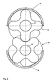
- zeigt eine Schnittansicht gemäß A-A der Fig. 1
- In den Figuren ist mit 10 das Gehäuse einer Pumpe bezeichnet, in dem zusammenwirkende Drehkolben 22 und 32 angeordnet sind, um Pumpvorgänge auszuführen. Nicht gezeigt sind der Einlass und der Auslass der Pumpe.
- Das Gehäuse 10 der Pumpe ist mit einer Platte 11 nach außen hin abgeschlossen, wobei durch die Platte hindurch zwei Bohrungen gelegt worden sind, die wiederum der Durchführung von Wellen 21 und 31 dienen.
- In der Fig. 1 sind zwei Hydraulikmotoren 20 und 30 gezeigt, und zwar nur schematisch und auch nur zum Teil. In jedem Falle sind diese Hydraulikmotoren 20 und 30 mit Wellenenden 21 und 31 ausgebildet, die von außen her in das Gehäuse 10, 11 der Pumpe hineinragen. Auf diese Wellenenden 21 und 31 sind die beiden Drehkolben 22 und 32 von axial außen zum Antrieb hin aufgeschoben.
- Die richtige Lage der Drehkolben 22 und 32 auf den Wellenenden 21 und 31 wird durch Hülsen sichergestellt, wobei in Fig. 1 lediglich die Hülse 23 für den oberen Drehkolben gezeigt ist. Die Hülse 23 dient nicht nur als Anschlag, sondern ist auch dazu gedacht, als Auflager für Laufbuchsen zu dienen, damit eine Wellenabdichtung 24 möglich ist.
- Im Zusammenhang mit der vorliegenden Erfindung ist es wesentlich, dass der Achsabstand der beiden Wellen 21 und 31 bzw. der Drehkolben 22 so klein gewählt worden ist, dass nur noch Hydraulikantriebe für den Antrieb der beiden Drehkolben in Frage kommen. Es wird ein gedrungener Aufbau der Pumpe insgesamt ermöglicht, wenn Hydraulikmotoren eingesetzt werden.
- Weiterhin ist für die Erfindung wesentlich, dass die beiden Drehkolben zueinander identisch ausgebildet sind.
- Bei der Pumpe gemäß der Erfindung ist es möglich, die beiden Drehkolben direkt auf das Antriebsende der Motoren aufzusetzen, zusätzliche separate Wellen sind nicht erforderlich.
- Auch können die Drehkolben aus Metall oder aus Kunststoff hergestellt werden und können eine entsprechende Beschichtung haben, so dass sie auch bei aggressiven Medien eingesetzt werden können.
Claims (5)
- Pumpe zur Förderung von Flüssigkeiten, von mit Partikeln beladenen Flüssigkeiten oder von Fluiden, aufweisend ein Paar miteinander kämmender mehrflügeliger schräg verzahnter Drehkolben (22, 32) die ihrerseits vermittels von Motoren (20, 30) angetrieben und in einem Pumpengehäuse (10) mit Einlass und Auslass gelagert sind, dadurch gekennzeichnet, dass die beiden zueinander identischen Drehkolben (22, 32) von zwei gleichen Hydraulikmotoren (20, 30) unabhängig voneinander angetrieben sind und dass die Hydraulikmotoren hydraulisch parallel geschaltet sind und stets die gleichen Drehmomente auf die Drehkolben übertragen.
- Pumpe nach Anspruch 1, dadurch gekennzeichnet, dass die Drehkolben (22, 23) einseitig gelagert sind.
- Pumpe nach Anspruch 2, dadurch gekennzeichnet, dass die Drehkolben (22, 32) auf den Wellenenden (21, 31) der Motoren (20, 30) gelagert sind.
- Pumpe nach Anspruch 3, dadurch gekennzeichnet, dass die Drehkolben (22, 32) auf die Wellenenden (21, 31) aufschiebbar sind.
- Pumpe nach Anspruch 4, dadurch gekennzeichnet, dass zwischen den Drehkolben (22, 32) und den Motoren (20, 30) jeweils eine Hülse (23) angeordnet ist.
Applications Claiming Priority (2)
| Application Number | Priority Date | Filing Date | Title |
|---|---|---|---|
| DE20314793U DE20314793U1 (de) | 2003-09-24 | 2003-09-24 | Hydraulisch angetriebene Pumpe |
| DE20314793U | 2003-09-24 |
Publications (2)
| Publication Number | Publication Date |
|---|---|
| EP1519044A1 EP1519044A1 (de) | 2005-03-30 |
| EP1519044B1 true EP1519044B1 (de) | 2006-06-21 |
Family
ID=34178076
Family Applications (1)
| Application Number | Title | Priority Date | Filing Date |
|---|---|---|---|
| EP04020942A Expired - Lifetime EP1519044B1 (de) | 2003-09-24 | 2004-09-03 | Drehkolbenpumpe, insbesondere zur Förderung von mit Partikeln beladenen Flüssigkeiten |
Country Status (3)
| Country | Link |
|---|---|
| EP (1) | EP1519044B1 (de) |
| AT (1) | ATE331140T1 (de) |
| DE (2) | DE20314793U1 (de) |
Cited By (3)
| Publication number | Priority date | Publication date | Assignee | Title |
|---|---|---|---|---|
| DE202012010401U1 (de) | 2012-10-31 | 2014-02-03 | Hugo Vogelsang Maschinenbau Gmbh | Drehkolbenpumpe mit Direktantrieb |
| DE202018107141U1 (de) | 2018-12-13 | 2020-03-18 | Vogelsang Gmbh & Co. Kg | Drehkolbenpumpe mit innenliegender Lagerung |
| DE102023119293A1 (de) | 2023-07-21 | 2025-01-23 | Vogelsang Gmbh & Co. Kg | Drehkolbenpumpe für den Einsatz in explosionsgefährdeter Umgebung |
Families Citing this family (3)
| Publication number | Priority date | Publication date | Assignee | Title |
|---|---|---|---|---|
| DE102008045440B4 (de) * | 2008-09-02 | 2017-02-09 | Börger GmbH | Drehkolben einer Drehkolbenpumpe und Drehkolbenpumpe |
| WO2018113898A1 (de) * | 2016-12-19 | 2018-06-28 | Renk-Maag Gmbh | Hydraulisches antriebssystem für eine förderpumpe |
| DE202022104656U1 (de) | 2022-08-17 | 2023-11-20 | Vogelsang Gmbh & Co. Kg | Pumpe zur Förderung eines Fluides |
Family Cites Families (5)
| Publication number | Priority date | Publication date | Assignee | Title |
|---|---|---|---|---|
| US3184155A (en) * | 1963-04-17 | 1965-05-18 | Cooper Bessemer Corp | Motor compressor unit |
| JP3074829B2 (ja) * | 1991-09-05 | 2000-08-07 | 松下電器産業株式会社 | 流体回転装置 |
| ES2140108T3 (es) * | 1995-06-21 | 2000-02-16 | Sterling Ind Consult Gmbh | Bomba de vacio. |
| DE19522555A1 (de) * | 1995-06-21 | 1997-01-02 | Sihi Ind Consult Gmbh | Rotationskolbenverdichter mit zwei Rotoren |
| DE20305937U1 (de) * | 2003-04-12 | 2004-05-19 | Hugo Vogelsang Maschinenbau Gmbh | Pumpe mit integriertem Hydraulik-Motor |
-
2003
- 2003-09-24 DE DE20314793U patent/DE20314793U1/de not_active Expired - Lifetime
-
2004
- 2004-09-03 EP EP04020942A patent/EP1519044B1/de not_active Expired - Lifetime
- 2004-09-03 AT AT04020942T patent/ATE331140T1/de not_active IP Right Cessation
- 2004-09-03 DE DE502004000814T patent/DE502004000814D1/de not_active Expired - Lifetime
Cited By (5)
| Publication number | Priority date | Publication date | Assignee | Title |
|---|---|---|---|---|
| DE202012010401U1 (de) | 2012-10-31 | 2014-02-03 | Hugo Vogelsang Maschinenbau Gmbh | Drehkolbenpumpe mit Direktantrieb |
| KR20150081317A (ko) * | 2012-10-31 | 2015-07-13 | 휴고 포겔상 마시네바우 게엠베하 | 다이렉트 드라이브를 가진 로터리 로브 펌프 |
| DE202018107141U1 (de) | 2018-12-13 | 2020-03-18 | Vogelsang Gmbh & Co. Kg | Drehkolbenpumpe mit innenliegender Lagerung |
| WO2020120746A1 (de) | 2018-12-13 | 2020-06-18 | Vogelsang Gmbh & Co. Kg | Drehkolbenpumpe mit innenliegender lagerung |
| DE102023119293A1 (de) | 2023-07-21 | 2025-01-23 | Vogelsang Gmbh & Co. Kg | Drehkolbenpumpe für den Einsatz in explosionsgefährdeter Umgebung |
Also Published As
| Publication number | Publication date |
|---|---|
| DE20314793U1 (de) | 2005-02-03 |
| EP1519044A1 (de) | 2005-03-30 |
| ATE331140T1 (de) | 2006-07-15 |
| DE502004000814D1 (de) | 2006-08-03 |
Similar Documents
| Publication | Publication Date | Title |
|---|---|---|
| DE3730966C2 (de) | Hermetisch geschlossener Rotationskolbenkompressor mit horizontaler Antriebswelle | |
| EP2122174B1 (de) | Integrierte innenzahnradpumpeneinheit mit elektrischem motor | |
| DE202019107293U1 (de) | Pumpenbaugruppe mit in einem einzelnen Gehäuse angeordneten zwei Pumpen | |
| EP2505335A2 (de) | Extrusionsvorrichtung zur Herstellung eines strangförmigen Profils oder Schlauches aus Kunststoff- oder Kautschukmasse | |
| DE10304121A1 (de) | Motorpumpenaggregat | |
| EP1927754A1 (de) | Innenzahnradpumpe | |
| DE10239558A1 (de) | Außenzahnradpumpe mit Druckfluidvorladung | |
| DE102012112618B3 (de) | Mehrfachpumpe | |
| DE3202993C2 (de) | Drehkolbenverdichter | |
| EP1519044A1 (de) | Drehkolbenpumpe, insbesondere zur Förderung von mit Partikeln beladenen Flüssigkeiten | |
| CN1379848A (zh) | 活塞泵 | |
| WO2007098849A1 (de) | Förderpumpe in einem kraftfahrzeug | |
| DE602004002679T2 (de) | Modulares getriebesystem für pumpe | |
| DE20305937U1 (de) | Pumpe mit integriertem Hydraulik-Motor | |
| DE10305585B3 (de) | Rotorpumpe | |
| DE102007007683A1 (de) | Antrieb für mindestens zwei Zusatzaggregate einer Brennkraftmaschine | |
| DE102022206319A1 (de) | Elektrische Zahnradpumpe für ein Kraftfahrzeug, insbesondere Gerotor-Pumpe sowie Set aus mehreren Zahnradpumpen | |
| EP0520943B1 (de) | Verdrängungspumpe | |
| DE102017223675B4 (de) | Fluidfördereinrichtung | |
| DE4121684C2 (de) | Pumpe | |
| DE112005000894T5 (de) | Vorrichtung zum Steuern bzw. Regeln von parasitären Verlusten in einer Fluidpumpe | |
| EP1831570B9 (de) | Pumpe, insbesondere dickstoffpumpe | |
| EP1218640B1 (de) | Hochdruckreinigungsgerät | |
| DE19959020A1 (de) | Hydroaggregat mit zumindest einer Verdrängermaschine, insbsondere mit einer Radialkolbenmaschine (Pumpen oder Motor) | |
| DE102016121388A1 (de) | Optimierter Rotor für eine Rotationspumpe |
Legal Events
| Date | Code | Title | Description |
|---|---|---|---|
| PUAI | Public reference made under article 153(3) epc to a published international application that has entered the european phase |
Free format text: ORIGINAL CODE: 0009012 |
|
| AK | Designated contracting states |
Kind code of ref document: A1 Designated state(s): AT BE BG CH CY CZ DE DK EE ES FI FR GB GR HU IE IT LI LU MC NL PL PT RO SE SI SK TR |
|
| AX | Request for extension of the european patent |
Extension state: AL HR LT LV MK |
|
| 17P | Request for examination filed |
Effective date: 20050826 |
|
| AKX | Designation fees paid |
Designated state(s): AT BE BG CH CY CZ DE DK EE ES FI FR GB GR HU IE IT LI LU MC NL PL PT RO SE SI SK TR |
|
| GRAP | Despatch of communication of intention to grant a patent |
Free format text: ORIGINAL CODE: EPIDOSNIGR1 |
|
| GRAS | Grant fee paid |
Free format text: ORIGINAL CODE: EPIDOSNIGR3 |
|
| GRAA | (expected) grant |
Free format text: ORIGINAL CODE: 0009210 |
|
| AK | Designated contracting states |
Kind code of ref document: B1 Designated state(s): AT BE BG CH CY CZ DE DK EE ES FI FR GB GR HU IE IT LI LU MC NL PL PT RO SE SI SK TR |
|
| PG25 | Lapsed in a contracting state [announced via postgrant information from national office to epo] |
Ref country code: SI Free format text: LAPSE BECAUSE OF FAILURE TO SUBMIT A TRANSLATION OF THE DESCRIPTION OR TO PAY THE FEE WITHIN THE PRESCRIBED TIME-LIMIT Effective date: 20060621 Ref country code: NL Free format text: LAPSE BECAUSE OF FAILURE TO SUBMIT A TRANSLATION OF THE DESCRIPTION OR TO PAY THE FEE WITHIN THE PRESCRIBED TIME-LIMIT Effective date: 20060621 Ref country code: PL Free format text: LAPSE BECAUSE OF FAILURE TO SUBMIT A TRANSLATION OF THE DESCRIPTION OR TO PAY THE FEE WITHIN THE PRESCRIBED TIME-LIMIT Effective date: 20060621 Ref country code: GB Free format text: LAPSE BECAUSE OF FAILURE TO SUBMIT A TRANSLATION OF THE DESCRIPTION OR TO PAY THE FEE WITHIN THE PRESCRIBED TIME-LIMIT Effective date: 20060621 Ref country code: CZ Free format text: LAPSE BECAUSE OF FAILURE TO SUBMIT A TRANSLATION OF THE DESCRIPTION OR TO PAY THE FEE WITHIN THE PRESCRIBED TIME-LIMIT Effective date: 20060621 Ref country code: RO Free format text: LAPSE BECAUSE OF FAILURE TO SUBMIT A TRANSLATION OF THE DESCRIPTION OR TO PAY THE FEE WITHIN THE PRESCRIBED TIME-LIMIT Effective date: 20060621 Ref country code: FI Free format text: LAPSE BECAUSE OF FAILURE TO SUBMIT A TRANSLATION OF THE DESCRIPTION OR TO PAY THE FEE WITHIN THE PRESCRIBED TIME-LIMIT Effective date: 20060621 Ref country code: IE Free format text: LAPSE BECAUSE OF FAILURE TO SUBMIT A TRANSLATION OF THE DESCRIPTION OR TO PAY THE FEE WITHIN THE PRESCRIBED TIME-LIMIT Effective date: 20060621 Ref country code: SK Free format text: LAPSE BECAUSE OF FAILURE TO SUBMIT A TRANSLATION OF THE DESCRIPTION OR TO PAY THE FEE WITHIN THE PRESCRIBED TIME-LIMIT Effective date: 20060621 |
|
| REG | Reference to a national code |
Ref country code: GB Ref legal event code: FG4D Free format text: NOT ENGLISH |
|
| REG | Reference to a national code |
Ref country code: CH Ref legal event code: EP |
|
| REG | Reference to a national code |
Ref country code: IE Ref legal event code: FG4D Free format text: LANGUAGE OF EP DOCUMENT: GERMAN |
|
| REF | Corresponds to: |
Ref document number: 502004000814 Country of ref document: DE Date of ref document: 20060803 Kind code of ref document: P |
|
| PG25 | Lapsed in a contracting state [announced via postgrant information from national office to epo] |
Ref country code: SE Free format text: LAPSE BECAUSE OF FAILURE TO SUBMIT A TRANSLATION OF THE DESCRIPTION OR TO PAY THE FEE WITHIN THE PRESCRIBED TIME-LIMIT Effective date: 20060921 Ref country code: DK Free format text: LAPSE BECAUSE OF FAILURE TO SUBMIT A TRANSLATION OF THE DESCRIPTION OR TO PAY THE FEE WITHIN THE PRESCRIBED TIME-LIMIT Effective date: 20060921 |
|
| PG25 | Lapsed in a contracting state [announced via postgrant information from national office to epo] |
Ref country code: MC Free format text: LAPSE BECAUSE OF NON-PAYMENT OF DUE FEES Effective date: 20060930 Ref country code: BE Free format text: LAPSE BECAUSE OF NON-PAYMENT OF DUE FEES Effective date: 20060930 |
|
| PG25 | Lapsed in a contracting state [announced via postgrant information from national office to epo] |
Ref country code: ES Free format text: LAPSE BECAUSE OF FAILURE TO SUBMIT A TRANSLATION OF THE DESCRIPTION OR TO PAY THE FEE WITHIN THE PRESCRIBED TIME-LIMIT Effective date: 20061002 |
|
| PG25 | Lapsed in a contracting state [announced via postgrant information from national office to epo] |
Ref country code: PT Free format text: LAPSE BECAUSE OF FAILURE TO SUBMIT A TRANSLATION OF THE DESCRIPTION OR TO PAY THE FEE WITHIN THE PRESCRIBED TIME-LIMIT Effective date: 20061121 |
|
| NLV1 | Nl: lapsed or annulled due to failure to fulfill the requirements of art. 29p and 29m of the patents act | ||
| ET | Fr: translation filed | ||
| REG | Reference to a national code |
Ref country code: IE Ref legal event code: FD4D |
|
| GBV | Gb: ep patent (uk) treated as always having been void in accordance with gb section 77(7)/1977 [no translation filed] |
Effective date: 20060621 |
|
| PLBE | No opposition filed within time limit |
Free format text: ORIGINAL CODE: 0009261 |
|
| STAA | Information on the status of an ep patent application or granted ep patent |
Free format text: STATUS: NO OPPOSITION FILED WITHIN TIME LIMIT |
|
| 26N | No opposition filed |
Effective date: 20070322 |
|
| PG25 | Lapsed in a contracting state [announced via postgrant information from national office to epo] |
Ref country code: AT Free format text: LAPSE BECAUSE OF NON-PAYMENT OF DUE FEES Effective date: 20060903 |
|
| BERE | Be: lapsed |
Owner name: HUGO VOGELSANG MASCHINENBAU G.M.B.H. Effective date: 20060930 |
|
| PG25 | Lapsed in a contracting state [announced via postgrant information from national office to epo] |
Ref country code: GR Free format text: LAPSE BECAUSE OF FAILURE TO SUBMIT A TRANSLATION OF THE DESCRIPTION OR TO PAY THE FEE WITHIN THE PRESCRIBED TIME-LIMIT Effective date: 20060922 |
|
| PG25 | Lapsed in a contracting state [announced via postgrant information from national office to epo] |
Ref country code: EE Free format text: LAPSE BECAUSE OF FAILURE TO SUBMIT A TRANSLATION OF THE DESCRIPTION OR TO PAY THE FEE WITHIN THE PRESCRIBED TIME-LIMIT Effective date: 20060621 Ref country code: BG Free format text: LAPSE BECAUSE OF FAILURE TO SUBMIT A TRANSLATION OF THE DESCRIPTION OR TO PAY THE FEE WITHIN THE PRESCRIBED TIME-LIMIT Effective date: 20060921 |
|
| PG25 | Lapsed in a contracting state [announced via postgrant information from national office to epo] |
Ref country code: TR Free format text: LAPSE BECAUSE OF FAILURE TO SUBMIT A TRANSLATION OF THE DESCRIPTION OR TO PAY THE FEE WITHIN THE PRESCRIBED TIME-LIMIT Effective date: 20060621 Ref country code: HU Free format text: LAPSE BECAUSE OF FAILURE TO SUBMIT A TRANSLATION OF THE DESCRIPTION OR TO PAY THE FEE WITHIN THE PRESCRIBED TIME-LIMIT Effective date: 20061222 Ref country code: LU Free format text: LAPSE BECAUSE OF NON-PAYMENT OF DUE FEES Effective date: 20060903 |
|
| PG25 | Lapsed in a contracting state [announced via postgrant information from national office to epo] |
Ref country code: CY Free format text: LAPSE BECAUSE OF FAILURE TO SUBMIT A TRANSLATION OF THE DESCRIPTION OR TO PAY THE FEE WITHIN THE PRESCRIBED TIME-LIMIT Effective date: 20060621 |
|
| REG | Reference to a national code |
Ref country code: CH Ref legal event code: PL |
|
| PG25 | Lapsed in a contracting state [announced via postgrant information from national office to epo] |
Ref country code: CH Free format text: LAPSE BECAUSE OF NON-PAYMENT OF DUE FEES Effective date: 20060930 Ref country code: LI Free format text: LAPSE BECAUSE OF NON-PAYMENT OF DUE FEES Effective date: 20060930 |
|
| PG25 | Lapsed in a contracting state [announced via postgrant information from national office to epo] |
Ref country code: CH Free format text: LAPSE BECAUSE OF NON-PAYMENT OF DUE FEES Effective date: 20080930 Ref country code: LI Free format text: LAPSE BECAUSE OF NON-PAYMENT OF DUE FEES Effective date: 20080930 |
|
| REG | Reference to a national code |
Ref country code: FR Ref legal event code: PLFP Year of fee payment: 13 |
|
| REG | Reference to a national code |
Ref country code: FR Ref legal event code: PLFP Year of fee payment: 14 |
|
| REG | Reference to a national code |
Ref country code: FR Ref legal event code: PLFP Year of fee payment: 15 |
|
| PGFP | Annual fee paid to national office [announced via postgrant information from national office to epo] |
Ref country code: FR Payment date: 20210927 Year of fee payment: 18 Ref country code: IT Payment date: 20210930 Year of fee payment: 18 |
|
| PG25 | Lapsed in a contracting state [announced via postgrant information from national office to epo] |
Ref country code: FR Free format text: LAPSE BECAUSE OF NON-PAYMENT OF DUE FEES Effective date: 20220930 |
|
| PG25 | Lapsed in a contracting state [announced via postgrant information from national office to epo] |
Ref country code: IT Free format text: LAPSE BECAUSE OF NON-PAYMENT OF DUE FEES Effective date: 20220903 |
|
| PGFP | Annual fee paid to national office [announced via postgrant information from national office to epo] |
Ref country code: DE Payment date: 20230929 Year of fee payment: 20 |
|
| REG | Reference to a national code |
Ref country code: DE Ref legal event code: R071 Ref document number: 502004000814 Country of ref document: DE |