EP1443210A2 - Motor-pump unit - Google Patents
Motor-pump unit Download PDFInfo
- Publication number
- EP1443210A2 EP1443210A2 EP03022470A EP03022470A EP1443210A2 EP 1443210 A2 EP1443210 A2 EP 1443210A2 EP 03022470 A EP03022470 A EP 03022470A EP 03022470 A EP03022470 A EP 03022470A EP 1443210 A2 EP1443210 A2 EP 1443210A2
- Authority
- EP
- European Patent Office
- Prior art keywords
- pumps
- pump
- motor
- electric motor
- rotor
- Prior art date
- Legal status (The legal status is an assumption and is not a legal conclusion. Google has not performed a legal analysis and makes no representation as to the accuracy of the status listed.)
- Granted
Links
Images
Classifications
-
- F—MECHANICAL ENGINEERING; LIGHTING; HEATING; WEAPONS; BLASTING
- F04—POSITIVE - DISPLACEMENT MACHINES FOR LIQUIDS; PUMPS FOR LIQUIDS OR ELASTIC FLUIDS
- F04C—ROTARY-PISTON, OR OSCILLATING-PISTON, POSITIVE-DISPLACEMENT MACHINES FOR LIQUIDS; ROTARY-PISTON, OR OSCILLATING-PISTON, POSITIVE-DISPLACEMENT PUMPS
- F04C11/00—Combinations of two or more machines or pumps, each being of rotary-piston or oscillating-piston type; Pumping installations
- F04C11/001—Combinations of two or more machines or pumps, each being of rotary-piston or oscillating-piston type; Pumping installations of similar working principle
-
- A—HUMAN NECESSITIES
- A61—MEDICAL OR VETERINARY SCIENCE; HYGIENE
- A61J—CONTAINERS SPECIALLY ADAPTED FOR MEDICAL OR PHARMACEUTICAL PURPOSES; DEVICES OR METHODS SPECIALLY ADAPTED FOR BRINGING PHARMACEUTICAL PRODUCTS INTO PARTICULAR PHYSICAL OR ADMINISTERING FORMS; DEVICES FOR ADMINISTERING FOOD OR MEDICINES ORALLY; BABY COMFORTERS; DEVICES FOR RECEIVING SPITTLE
- A61J1/00—Containers specially adapted for medical or pharmaceutical purposes
- A61J1/03—Containers specially adapted for medical or pharmaceutical purposes for pills or tablets
-
- F—MECHANICAL ENGINEERING; LIGHTING; HEATING; WEAPONS; BLASTING
- F04—POSITIVE - DISPLACEMENT MACHINES FOR LIQUIDS; PUMPS FOR LIQUIDS OR ELASTIC FLUIDS
- F04C—ROTARY-PISTON, OR OSCILLATING-PISTON, POSITIVE-DISPLACEMENT MACHINES FOR LIQUIDS; ROTARY-PISTON, OR OSCILLATING-PISTON, POSITIVE-DISPLACEMENT PUMPS
- F04C15/00—Component parts, details or accessories of machines, pumps or pumping installations, not provided for in groups F04C2/00 - F04C14/00
- F04C15/0057—Driving elements, brakes, couplings, transmission specially adapted for machines or pumps
- F04C15/008—Prime movers
Definitions
- the invention relates to a motor pump unit comprising an electric motor and a pump.
- the motor and pump are interleaved; the Motor envelops the pump.
- EP 0 611 887 A1 describes a further motor pump unit.
- the rotor of the motor is an independent component, but with the cylinder block a piston pump rotatably connected.
- Units of this type have the great advantage that they only have one occupy minimal space. But there is still room for improvement.
- the invention has for its object a motor pump unit mentioned design to improve even further, especially with regard to the Manufacturing effort and space requirements.
- the invention is based on the aforementioned WO document, but with one Multiplication of the individual units.
- a preferred Embodiment comprises the entire motor pump unit two axially internal gear pumps aligned with one another and an electric motor which which is assigned to one of the two pumps. They are each other neighboring pumps are assigned to each other in such a way that they single electric motor can be driven. It gets involved with it achieve high delivery volume and / or high delivery pressure.
- a large The advantage is that the two pumps are within a single housing are arranged so that when operating the entire aggregate of oil are enclosed and therefore no seals are required.
- the two pumps can be completely identical. But you can too have different diameters in the conveying area, i.e. where the Conveyor tooth limit.
- Asynchronous motors for example Asynchronous motors, reluctance motors or so-called squirrel-cage rotors.
- the invention can be used particularly advantageously in the case of internal gear pumps apply.
- the pump forms a completely independent, self-sufficient unit. It can be Manufacture separately, check separately and completely in the stator of the Install the electric motor enclosed space.
- the engine is cooled with oil.
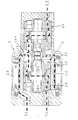
- the motor pump unit comprises an electric motor 1 with a Stator laminated core 1.1, a winding 1.2 and a rotor 1.3.
- first internal gear pump 2 This has a pinion 2.1 on, a compared to this eccentric ring gear 2.2 and a pinion shaft 2.3.
- the pinion shaft 2.3 is mounted in side windows 2.4, 2.5.
- the two elements, motor and first pump, are common Enclosed housing 3.
- housing 3 In the housing 3 there is an inlet 3.1 and a first outlet 3.2 for the medium to be pumped.
- the rotor 1.3 of the motor 1 is pot-shaped. In the present axial section it appears U-shaped.
- the pinion shaft 2.3 projects with the rotor 1.3 a toothing 2.3.1 in rotary connection.
- web 1.3.1 of the U is namely an internal toothing, while the pinion shaft a corresponding Has external teeth. Comb the internal teeth and external teeth together.
- the rotor 1.3 is mounted on the first pump 2, more precisely on the Ring gear 2.3 and the side windows 2.4, 2.5.
- a second internal gear pump is provided. This is arranged axially next to the first pump 2, in such a way that the The axes of the two pumps are aligned.
- the housing 3 is over the led out first pump 2 and flows around the second pump 20th
- the second pump 20 is identical in construction to the first pump 2. It has accordingly also a pinion shaft 20.3, which with the pinion shaft 2.3 is structurally identical and which also has a toothing 20.3.1 with the rotor 1.3 is in rotary connection.
- the housing 3 has a second outlet 3.3.
- the second pump 20 is fixed on the right cover of the housing 3.
- the cup-shaped rotor thus drives 1.3 the two pinion shafts 2.3, 20.3.
- the course of the oil is shown by the bold arrows.
- the oil will at inlet 3.1, shown in the figure on the left, sucked in, passes through the gap between the stator laminated core 1.1 and the rotor 1.3 in the space between the two pumps 2 and 20.
- the oil flow divides there.
- a partial flow occurs through the pump 2 and at the first outlet 3.2 again, and on second partial flow passes through the second pump 20 and on the second Spout 3.2 out.
- the motor pump unit thus has a suction connection and two pressure connections.
Landscapes
- Engineering & Computer Science (AREA)
- Mechanical Engineering (AREA)
- General Engineering & Computer Science (AREA)
- Health & Medical Sciences (AREA)
- Pharmacology & Pharmacy (AREA)
- Life Sciences & Earth Sciences (AREA)
- Animal Behavior & Ethology (AREA)
- General Health & Medical Sciences (AREA)
- Public Health (AREA)
- Veterinary Medicine (AREA)
- Rotary Pumps (AREA)
- Details And Applications Of Rotary Liquid Pumps (AREA)
- Connection Of Motors, Electrical Generators, Mechanical Devices, And The Like (AREA)
- Control Of Electric Motors In General (AREA)
- Compressor (AREA)
- Reciprocating Pumps (AREA)
Abstract
Description
Die Erfindung betrifft ein Motorpumpenaggregat, umfassend einen Elektromotor und eine Pumpe. Dabei sind Motor und Pumpe ineinander verschachtelt; der Motor umhüllt die Pumpe. Auf WO 01/73295 wird verwiesen.The invention relates to a motor pump unit comprising an electric motor and a pump. The motor and pump are interleaved; the Motor envelops the pump. Reference is made to WO 01/73295.
DE 195 38 278 A1 beschreibt ein ähnliches Motorpumpenaggregat. Dabei ist der Rotor des Elektromotors gleichzeitig das Pumpenrad der Pumpe.DE 195 38 278 A1 describes a similar motor pump unit. It is the rotor of the electric motor simultaneously the pump impeller of the pump.
EP 0 611 887 A1 beschreibt ein weiteres Motorpumpenaggregat. Dabei ist der Rotor des Motors zwar ein eigenständiges Bauteil, aber mit dem Zylinderblock einer Kolbenpumpe drehfest verbunden.EP 0 611 887 A1 describes a further motor pump unit. Here is the The rotor of the motor is an independent component, but with the cylinder block a piston pump rotatably connected.
Aggregate dieser Bauart haben den großen Vorteil, dass sie nur einen minimalen Raum beanspruchen. Sie sind aber noch verbesserungsfähig.Units of this type have the great advantage that they only have one occupy minimal space. But there is still room for improvement.
Der Erfindung liegt die Aufgabe zugrunde, ein Motorpumpenaggregat der genannten Bauart noch weiter zu verbessern, insbesondere bezüglich des Fertigungsaufwandes und des Raumbedarfs.The invention has for its object a motor pump unit mentioned design to improve even further, especially with regard to the Manufacturing effort and space requirements.
Diese Aufgabe wird durch die Merkmale von Anspruch 1 gelöst.This object is solved by the features of claim 1.
Die Erfindung geht aus von der genannten WO-Schrift, jedoch mit einer Vervielfachung der einzelnen Aggregate. Gemäß einer bevorzugten Ausführungsform umfasst das gesamte Motorpumpenaggregat zwei axial miteinander fluchtende Innnenzahnradpumpen sowie einen Elektromotor, der der einen der beiden Pumpe zugeordnet ist. Dabei sind die einander benachbarten Pumpen einander derart zugeordnet, dass sie von einem einzigen Elektromotor angetrieben werden können. Es lässt sich damit ein hohes Fördervolumen und/ oder ein hoher Förderdruck erzielen. Ein großer Vorteil liegt darin, dass die beiden Pumpen innerhalb eines einzigen Gehäuses angeordnet sind, so dass sie beim Betrieb des gesamten Aggregates von Öl umschlossen sind und daher keine Dichtungen benötigt werden.The invention is based on the aforementioned WO document, but with one Multiplication of the individual units. According to a preferred Embodiment comprises the entire motor pump unit two axially internal gear pumps aligned with one another and an electric motor which which is assigned to one of the two pumps. They are each other neighboring pumps are assigned to each other in such a way that they single electric motor can be driven. It gets involved with it achieve high delivery volume and / or high delivery pressure. A large The advantage is that the two pumps are within a single housing are arranged so that when operating the entire aggregate of oil are enclosed and therefore no seals are required.
Die beiden Pumpen können völlig baugleich sein. Sie können aber auch unterschiedliche Durchmesser im Förderbereich haben, d.h. dort, wo sich die Förderzahngrenze befinden.The two pumps can be completely identical. But you can too have different diameters in the conveying area, i.e. where the Conveyor tooth limit.
Es kommen verschiedene Arten von Elektromotoren in Betracht, beispielsweise Asynchronmotoren, Reluktanzmotoren oder sogenannte Kurzschlussläufer.Different types of electric motors come into consideration, for example Asynchronous motors, reluctance motors or so-called squirrel-cage rotors.
Es kommen auch die unterschiedlichsten Arten von Pumpen in Betracht. Besonders vorteilhaft lässt sich die Erfindung bei Innenzahnradpumpen anwenden.Different types of pumps can also be considered. The invention can be used particularly advantageously in the case of internal gear pumps apply.
Die Pumpe bildet dabei eine völlig selbständige, autarke Einheit. Sie lässt sich separat herstellen, separat prüfen sowie komplett in den vom Stator des Elektromotors umschlossenen Raum einbauen.The pump forms a completely independent, self-sufficient unit. It can be Manufacture separately, check separately and completely in the stator of the Install the electric motor enclosed space.
Der Motor wird mit Öl gekühlt.The engine is cooled with oil.
Dabei ist es möglich, den Rotor des Elektromotors auf dem Gehäuse der betreffenden Innenzahnradpumpe zu lagern.It is possible to place the rotor of the electric motor on the housing store the relevant internal gear pump.
Die Erfindung ist anhand der Zeichnungen erläutert. Darin ist im einzelnen folgendes dargestellt:The invention is explained with reference to the drawings. In it is in detail shown the following:
Das Motorpumpenaggregat umfasst einen Elektromotor 1 mit einem Statorblechpaket 1.1, einer Wicklung 1.2 und einem Rotor 1.3.The motor pump unit comprises an electric motor 1 with a Stator laminated core 1.1, a winding 1.2 and a rotor 1.3.
Es umfasst ferner eine erste Innenzahnradpumpe 2. Diese weist ein Ritzel 2.1 auf, ein gegenüber diesem exzentrischen Hohlrad 2.2 sowie einer Ritzelwelle 2.3. Die Ritzelwelle 2.3 ist in Seitenscheiben 2.4, 2.5 gelagert. Im vorliegenden Falle sind Gleitlager 2.4.1, 2.5.1 vorgesehen.It also includes a first internal gear pump 2. This has a pinion 2.1 on, a compared to this eccentric ring gear 2.2 and a pinion shaft 2.3. The pinion shaft 2.3 is mounted in side windows 2.4, 2.5. In the present Cases are provided bearings 2.4.1, 2.5.1.
Die beiden Elemente Motor und erste Pumpe sind von einem gemeinsamen
Gehäuse 3 umschlossen. Im Gehäuse 3 befinden sich ein Zulauf 3.1 sowie ein
erster Auslauf 3.2 für das zu pumpende Medium.The two elements, motor and first pump, are common
Enclosed
Der Rotor 1.3 des Motors 1 ist topfförmig gestaltet. Im vorliegenden Axialschnitt erscheint er U-förmig. Dabei steht die Ritzelwelle 2.3 mit dem Rotor 1.3 über eine Verzahnung 2.3.1 in Drehverbindung. Im Steg 1.3.1 des U befindet sich nämlich eine Innenverzahnung, während die Ritzelwelle eine entsprechende Außenverzahnung aufweist. Innenverzahnung und Außenverzahnung kämmen miteinander.The rotor 1.3 of the motor 1 is pot-shaped. In the present axial section it appears U-shaped. The pinion shaft 2.3 projects with the rotor 1.3 a toothing 2.3.1 in rotary connection. In web 1.3.1 of the U is namely an internal toothing, while the pinion shaft a corresponding Has external teeth. Comb the internal teeth and external teeth together.
Es könnte auch eine anderweitige Triebverbindung zwischen dem Rotor 1.3 des Motors 1 und der Ritzelwelle 2.3 hergestellt sein. So ist es denkbar, zwischen diesen beiden nicht nur eine einzige, sondern zwei oder mehrere Verzahnungen mit entsprechenden Drehmoment übertragenden Elementen vorzusehen, so dass eine Übersetzung von der Drehzahl des Rotors zur Ritzelwelle ins Langsame oder ins Schnelle erfolgt.There could also be another drive connection between the rotor 1.3 of the Motor 1 and the pinion shaft 2.3 be made. So it is conceivable between these two not just one, but two or more Gears with corresponding torque-transmitting elements to be provided so that a translation from the speed of the rotor to Pinion shaft in slow or fast.
Der Rotor 1.3 ist auf der ersten Pumpe 2 gelagert, genauer gesagt auf dem Hohlrad 2.3 und den Seitenscheiben 2.4, 2.5.The rotor 1.3 is mounted on the first pump 2, more precisely on the Ring gear 2.3 and the side windows 2.4, 2.5.
Gemäß der Erfindung ist eine zweite Innenzahnradpumpe vorgesehen. Diese
ist axial neben der ersten Pumpe 2 angeordnet, und zwar derart, dass die
Achsen der beiden Pumpen miteinander fluchten. Das Gehäuse 3 ist über die
erste Pumpe 2 hinausgeführt und umfließt auch die zweite Pumpe 20.According to the invention, a second internal gear pump is provided. This
is arranged axially next to the first pump 2, in such a way that the
The axes of the two pumps are aligned. The
Die zweite Pumpe 20 ist baugleich mit der ersten Pumpe 2. Sie weist
demgemäss auch eine Ritzelwelle 20.3 auf, die mit der Ritzelwelle 2.3
baugleich ist und die ebenfalls über eine Verzahnung 20.3.1 mit dem Rotor 1.3
in Drehverbindung steht.The
Das Gehäuse 3 weist einen zweiten Auslauf 3.3 auf.The
Die zweite Pumpe 20 ist am rechten Deckel des Gehäuses 3 fixiert.The
Bei der erfindungsgemäßen Ausführungsform treibt somit der topfförmige Rotor 1.3 die beiden Ritzelwellen 2.3, 20.3 an.In the embodiment according to the invention, the cup-shaped rotor thus drives 1.3 the two pinion shafts 2.3, 20.3.
Der Verlauf des Öles ist durch die fettgedruckten Pfeile dargestellt. Das Öl wird
bei Zulauf 3.1, in der Figur links dargestellt, angesaugt, gelangt durch den Spalt
zwischen Statorblechpaket 1.1 und Rotor 1.3 in den Zwischenraum zwischen
den beiden Pumpen 2 und 20. Dort teilt sich der Ölstrom auf. Ein Teilstrom tritt
durch die Pumpe 2 hindurch und am ersten Auslauf 3.2 wieder aus, und ein
zweiter Teilstrom tritt durch die zweite Pumpe 20 hindurch und am zweiten
Auslauf 3.2 aus. Das Motorpumpenaggregat hat somit einen Sauganschluss
und zwei Druckanschlüsse.The course of the oil is shown by the bold arrows. The oil will
at inlet 3.1, shown in the figure on the left, sucked in, passes through the gap
between the stator laminated core 1.1 and the rotor 1.3 in the space between
the two
Claims (1)
Applications Claiming Priority (2)
| Application Number | Priority Date | Filing Date | Title |
|---|---|---|---|
| DE10304121A DE10304121A1 (en) | 2003-01-31 | 2003-01-31 | A motor pump assembly |
| DE10304121 | 2003-01-31 |
Publications (4)
| Publication Number | Publication Date |
|---|---|
| EP1443210A2 true EP1443210A2 (en) | 2004-08-04 |
| EP1443210A3 EP1443210A3 (en) | 2005-08-10 |
| EP1443210B1 EP1443210B1 (en) | 2006-08-02 |
| EP1443210B8 EP1443210B8 (en) | 2006-09-06 |
Family
ID=32603100
Family Applications (1)
| Application Number | Title | Priority Date | Filing Date |
|---|---|---|---|
| EP03022470A Expired - Lifetime EP1443210B8 (en) | 2003-01-31 | 2003-10-08 | Motor-pump unit |
Country Status (6)
| Country | Link |
|---|---|
| US (1) | US7381036B2 (en) |
| EP (1) | EP1443210B8 (en) |
| JP (1) | JP3971369B2 (en) |
| KR (1) | KR20040069989A (en) |
| AT (1) | ATE335132T1 (en) |
| DE (2) | DE10304121A1 (en) |
Cited By (4)
| Publication number | Priority date | Publication date | Assignee | Title |
|---|---|---|---|---|
| WO2008028546A1 (en) * | 2006-09-08 | 2008-03-13 | Voith Turbo Gmbh & Co. Kg | Hydrostatic energy generation unit |
| EP2924291A3 (en) * | 2014-02-25 | 2015-10-14 | LG Innotek Co., Ltd. | Electric pump |
| CN105464964A (en) * | 2015-12-31 | 2016-04-06 | 太仓顺达磁力泵科技有限公司 | Conveying pump for solid-liquid mixed materials |
| EP4575229A1 (en) * | 2023-12-19 | 2025-06-25 | Rolls-Royce plc | Positive displacement pump system |
Families Citing this family (16)
| Publication number | Priority date | Publication date | Assignee | Title |
|---|---|---|---|---|
| JP2005273648A (en) * | 2004-02-23 | 2005-10-06 | Aisin Seiki Co Ltd | Electric pump |
| DE202005005620U1 (en) * | 2005-04-08 | 2006-08-17 | Hawe Hydraulik Gmbh & Co. Kg | pump unit |
| FR2918718B1 (en) * | 2007-07-10 | 2013-06-28 | Inergy Automotive Systems Res | ROTARY PUMP FOR VEHICLE. |
| JP2009191754A (en) * | 2008-02-15 | 2009-08-27 | Toyota Industries Corp | Variable displacement gear pump |
| JP5860695B2 (en) * | 2011-12-28 | 2016-02-16 | Kyb株式会社 | Electric oil pump |
| JP5767996B2 (en) * | 2012-03-29 | 2015-08-26 | カヤバ工業株式会社 | Fluid pressure drive unit |
| JP5934543B2 (en) * | 2012-03-29 | 2016-06-15 | Kyb株式会社 | Fluid pressure drive unit |
| DE102015015863A1 (en) * | 2015-12-09 | 2017-06-14 | Fte Automotive Gmbh | Electric motor driven liquid pump |
| WO2018062107A1 (en) * | 2016-09-30 | 2018-04-05 | 日本電産トーソク株式会社 | Pump device |
| DE102016225923B4 (en) | 2016-12-21 | 2020-06-18 | Hawe Hydraulik Se | Pump unit for a hydraulic system and channel element for a pump unit |
| DE102019200560B4 (en) * | 2018-09-14 | 2025-04-30 | Hanon Systems Efp Deutschland Gmbh | Gerotor pump and method for achieving pressure equalization in a gerotor pump |
| WO2020100042A1 (en) * | 2018-11-13 | 2020-05-22 | Ghsp, Inc. | Modular fluid pump for use in diverse applications |
| CN121066823A (en) * | 2019-06-19 | 2025-12-05 | 浙江三花智能控制股份有限公司 | Electric pump |
| CN111102202A (en) * | 2019-12-21 | 2020-05-05 | 郭伟聪 | Multi-azimuth liquid long-distance conveying device |
| US11990819B2 (en) | 2020-11-24 | 2024-05-21 | Bosch Rexroth Corporation | Electric and hydraulic machine |
| DE102023116639A1 (en) * | 2023-06-23 | 2024-12-24 | Valeo Embrayages | hydraulic pump |
Family Cites Families (18)
| Publication number | Priority date | Publication date | Assignee | Title |
|---|---|---|---|---|
| US2420124A (en) * | 1944-11-27 | 1947-05-06 | Coulson Charles Chilton | Motor-compressor unit |
| US2691346A (en) * | 1948-09-07 | 1954-10-12 | F E Myers & Bro Co | Double rotary fluid pump |
| US2711286A (en) * | 1952-08-01 | 1955-06-21 | Wetmore Hodges | Motor-pump or compressor |
| US2871793A (en) * | 1956-06-29 | 1959-02-03 | Robbins & Myers | Electric motor and pump combination |
| FR1458497A (en) * | 1965-09-23 | 1966-03-04 | Outil Hydraulique B G | Flow distributor-synchronizer |
| DE2938276A1 (en) * | 1979-09-21 | 1981-04-09 | Robert Bosch Gmbh, 7000 Stuttgart | WING CELL COMPRESSORS |
| WO1987006654A1 (en) * | 1986-04-23 | 1987-11-05 | Svenska Rotor Maskiner Ab | Rotary positive displacement machine for a compressible working fluid |
| DE3614819A1 (en) * | 1986-05-02 | 1987-11-12 | Kloeckner Humboldt Deutz Ag | INTERNAL-TOOTHED DOUBLE PUMP WITH COMMON SUCTION AND SEPARATE PRESSURE OUTPUTS |
| JP2687822B2 (en) | 1992-08-06 | 1997-12-08 | ダイキン工業株式会社 | Fluid pressure generator |
| EP0769621A1 (en) * | 1995-09-26 | 1997-04-23 | Fraunhofer-Gesellschaft Zur Förderung Der Angewandten Forschung E.V. | Micropump and micromotor |
| DE19538278A1 (en) | 1995-10-15 | 1996-05-02 | Sbs Sondermaschinen Gmbh | Rotary pump with electric drive e.g. for use in heating and sanitation equipment engineering |
| US5857842A (en) * | 1997-06-16 | 1999-01-12 | Sheehan; Kevin | Seamless pump with coaxial magnetic coupling including stator and rotor |
| DE19817162A1 (en) * | 1998-04-17 | 1999-10-21 | Sachsenhydraulik Gmbh | Electrohydraulic compact drive |
| DE69904834T2 (en) * | 1998-08-06 | 2003-08-14 | Automotive Motion Technology Ltd., Andover | ELECTRICALLY DRIVEN PUMP |
| DE10015139A1 (en) * | 2000-03-29 | 2001-10-11 | Voith Turbo Kg | Motor pump unit |
| US6733249B2 (en) * | 2001-05-17 | 2004-05-11 | Delphi Technologies, Inc. | Multi-stage internal gear fuel pump |
| US6699024B2 (en) * | 2001-06-29 | 2004-03-02 | Parker Hannifin Corporation | Hydraulic motor |
| KR100875749B1 (en) * | 2002-07-02 | 2008-12-24 | 엘지전자 주식회사 | Hermetic compressor |
-
2003
- 2003-01-31 DE DE10304121A patent/DE10304121A1/en not_active Ceased
- 2003-10-08 EP EP03022470A patent/EP1443210B8/en not_active Expired - Lifetime
- 2003-10-08 DE DE50304454T patent/DE50304454D1/en not_active Expired - Lifetime
- 2003-10-08 AT AT03022470T patent/ATE335132T1/en not_active IP Right Cessation
- 2003-11-26 JP JP2003396239A patent/JP3971369B2/en not_active Expired - Fee Related
-
2004
- 2004-01-15 KR KR1020040002837A patent/KR20040069989A/en not_active Withdrawn
- 2004-01-30 US US10/768,495 patent/US7381036B2/en not_active Expired - Fee Related
Cited By (7)
| Publication number | Priority date | Publication date | Assignee | Title |
|---|---|---|---|---|
| WO2008028546A1 (en) * | 2006-09-08 | 2008-03-13 | Voith Turbo Gmbh & Co. Kg | Hydrostatic energy generation unit |
| KR20090074028A (en) * | 2006-09-08 | 2009-07-03 | 보이트 터보 게엠베하 운트 콤파니 카게 | Hydrostatic Power Generation Device |
| US8143754B2 (en) | 2006-09-08 | 2012-03-27 | Voith Turbo Gmbh & Co. Kg | Hydrostatic energy generation unit |
| EP2924291A3 (en) * | 2014-02-25 | 2015-10-14 | LG Innotek Co., Ltd. | Electric pump |
| US10190584B2 (en) | 2014-02-25 | 2019-01-29 | Lg Innotek Co., Ltd. | Electric pump |
| CN105464964A (en) * | 2015-12-31 | 2016-04-06 | 太仓顺达磁力泵科技有限公司 | Conveying pump for solid-liquid mixed materials |
| EP4575229A1 (en) * | 2023-12-19 | 2025-06-25 | Rolls-Royce plc | Positive displacement pump system |
Also Published As
| Publication number | Publication date |
|---|---|
| EP1443210B1 (en) | 2006-08-02 |
| US7381036B2 (en) | 2008-06-03 |
| JP3971369B2 (en) | 2007-09-05 |
| ATE335132T1 (en) | 2006-08-15 |
| US20040219035A1 (en) | 2004-11-04 |
| DE50304454D1 (en) | 2006-09-14 |
| JP2004232627A (en) | 2004-08-19 |
| EP1443210B8 (en) | 2006-09-06 |
| EP1443210A3 (en) | 2005-08-10 |
| DE10304121A1 (en) | 2004-08-12 |
| KR20040069989A (en) | 2004-08-06 |
Similar Documents
| Publication | Publication Date | Title |
|---|---|---|
| EP1181453B1 (en) | Motor-pump unit | |
| EP1443210B1 (en) | Motor-pump unit | |
| EP2122174B1 (en) | Integrated internal gear pump with an electric motor | |
| CH669979A5 (en) | ||
| EP2473740A1 (en) | Two-stage centrifugal pump | |
| EP1536139B1 (en) | Pump unit with a gear pump and an electric motor | |
| DE3202993C2 (en) | Rotary lobe compressors | |
| DE3407081C2 (en) | ||
| EP1526282B1 (en) | Motor-pump unit | |
| EP1413757A2 (en) | Assembly of a motor and a pump | |
| DE102022206319A1 (en) | Electric gear pump for a motor vehicle, in particular a gerotor pump and a set of several gear pumps | |
| EP1777411A1 (en) | Motor-pump unit | |
| WO2023174888A1 (en) | Oil pump for a motor vehicle | |
| DE4038704C2 (en) | Rotary lobe pump | |
| WO2006120138A1 (en) | Internal gear fuel pump | |
| DE102010063517A1 (en) | Pump, compressor or motor multi-stage or multi-flow | |
| EP1989448A1 (en) | Oil-pump and vacuum-pump module | |
| DE102005029967A1 (en) | Dual clutch transmission of vehicle, comprises pump unit attached to second part of clutch housing | |
| DE19980647B4 (en) | Scroll compressor with an eccentric crank mechanism comprising an elongated shaft | |
| WO2026027324A1 (en) | Electric displacement pump and oil flow circuit in the electric displacement pump | |
| DE4234055A1 (en) | Spiral compressor | |
| DE102024110150A1 (en) | Fluid pump | |
| EP1030963A1 (en) | Induction pipe with insertable components | |
| DE9018104U1 (en) | Rotary lobe pump | |
| WO2023134809A1 (en) | Tandem pump comprising a main flow and a dry sump flow |
Legal Events
| Date | Code | Title | Description |
|---|---|---|---|
| PUAI | Public reference made under article 153(3) epc to a published international application that has entered the european phase |
Free format text: ORIGINAL CODE: 0009012 |
|
| AK | Designated contracting states |
Kind code of ref document: A2 Designated state(s): AT BE BG CH CY CZ DE DK EE ES FI FR GB GR HU IE IT LI LU MC NL PT RO SE SI SK TR |
|
| AX | Request for extension of the european patent |
Extension state: AL LT LV MK |
|
| PUAL | Search report despatched |
Free format text: ORIGINAL CODE: 0009013 |
|
| AK | Designated contracting states |
Kind code of ref document: A3 Designated state(s): AT BE BG CH CY CZ DE DK EE ES FI FR GB GR HU IE IT LI LU MC NL PT RO SE SI SK TR |
|
| AX | Request for extension of the european patent |
Extension state: AL LT LV MK |
|
| RIC1 | Information provided on ipc code assigned before grant |
Ipc: 7F 04C 15/00 B Ipc: 7F 04C 2/10 B Ipc: 7F 04C 11/00 A |
|
| 17P | Request for examination filed |
Effective date: 20050803 |
|
| GRAP | Despatch of communication of intention to grant a patent |
Free format text: ORIGINAL CODE: EPIDOSNIGR1 |
|
| AKX | Designation fees paid |
Designated state(s): AT BE BG CH CY CZ DE DK EE ES FI FR GB GR HU IE IT LI LU MC NL PT RO SE SI SK TR |
|
| GRAS | Grant fee paid |
Free format text: ORIGINAL CODE: EPIDOSNIGR3 |
|
| GRAA | (expected) grant |
Free format text: ORIGINAL CODE: 0009210 |
|
| AK | Designated contracting states |
Kind code of ref document: B1 Designated state(s): AT BE BG CH CY CZ DE DK EE ES FI FR GB GR HU IE IT LI LU MC NL PT RO SE SI SK TR |
|
| PG25 | Lapsed in a contracting state [announced via postgrant information from national office to epo] |
Ref country code: IT Free format text: LAPSE BECAUSE OF FAILURE TO SUBMIT A TRANSLATION OF THE DESCRIPTION OR TO PAY THE FEE WITHIN THE PRESCRIBED TIME-LIMIT;WARNING: LAPSES OF ITALIAN PATENTS WITH EFFECTIVE DATE BEFORE 2007 MAY HAVE OCCURRED AT ANY TIME BEFORE 2007. THE CORRECT EFFECTIVE DATE MAY BE DIFFERENT FROM THE ONE RECORDED. Effective date: 20060802 Ref country code: SK Free format text: LAPSE BECAUSE OF FAILURE TO SUBMIT A TRANSLATION OF THE DESCRIPTION OR TO PAY THE FEE WITHIN THE PRESCRIBED TIME-LIMIT Effective date: 20060802 Ref country code: FI Free format text: LAPSE BECAUSE OF FAILURE TO SUBMIT A TRANSLATION OF THE DESCRIPTION OR TO PAY THE FEE WITHIN THE PRESCRIBED TIME-LIMIT Effective date: 20060802 Ref country code: CZ Free format text: LAPSE BECAUSE OF FAILURE TO SUBMIT A TRANSLATION OF THE DESCRIPTION OR TO PAY THE FEE WITHIN THE PRESCRIBED TIME-LIMIT Effective date: 20060802 Ref country code: SI Free format text: LAPSE BECAUSE OF FAILURE TO SUBMIT A TRANSLATION OF THE DESCRIPTION OR TO PAY THE FEE WITHIN THE PRESCRIBED TIME-LIMIT Effective date: 20060802 Ref country code: IE Free format text: LAPSE BECAUSE OF FAILURE TO SUBMIT A TRANSLATION OF THE DESCRIPTION OR TO PAY THE FEE WITHIN THE PRESCRIBED TIME-LIMIT Effective date: 20060802 Ref country code: RO Free format text: LAPSE BECAUSE OF FAILURE TO SUBMIT A TRANSLATION OF THE DESCRIPTION OR TO PAY THE FEE WITHIN THE PRESCRIBED TIME-LIMIT Effective date: 20060802 Ref country code: NL Free format text: LAPSE BECAUSE OF FAILURE TO SUBMIT A TRANSLATION OF THE DESCRIPTION OR TO PAY THE FEE WITHIN THE PRESCRIBED TIME-LIMIT Effective date: 20060802 |
|
| REG | Reference to a national code |
Ref country code: GB Ref legal event code: FG4D Free format text: NOT ENGLISH |
|
| RAP2 | Party data changed (patent owner data changed or rights of a patent transferred) |
Owner name: VOITH TURBO GMBH & CO. KG |
|
| REG | Reference to a national code |
Ref country code: GB Ref legal event code: ERR Free format text: NOTIFICATION HAS NOW BEEN RECEIVED FROM THE EUROPEAN PATENT OFFICE THAT THE CORRECT NAME IS: VOITH TURBO GMBH & CO KG THIS CORRECTION WILL BE PUBLISHED IN THE EUROPEAN PATENT BULLETIN 06/33 DATED 20060816 |
|
| REG | Reference to a national code |
Ref country code: CH Ref legal event code: EP |
|
| REG | Reference to a national code |
Ref country code: IE Ref legal event code: FG4D Free format text: LANGUAGE OF EP DOCUMENT: GERMAN |
|
| REF | Corresponds to: |
Ref document number: 50304454 Country of ref document: DE Date of ref document: 20060914 Kind code of ref document: P |
|
| NLT2 | Nl: modifications (of names), taken from the european patent patent bulletin |
Owner name: VOITH TURBO GMBH & CO. KG Effective date: 20060816 |
|
| GBT | Gb: translation of ep patent filed (gb section 77(6)(a)/1977) |
Effective date: 20060913 |
|
| PG25 | Lapsed in a contracting state [announced via postgrant information from national office to epo] |
Ref country code: MC Free format text: LAPSE BECAUSE OF NON-PAYMENT OF DUE FEES Effective date: 20061031 |
|
| PG25 | Lapsed in a contracting state [announced via postgrant information from national office to epo] |
Ref country code: DK Free format text: LAPSE BECAUSE OF FAILURE TO SUBMIT A TRANSLATION OF THE DESCRIPTION OR TO PAY THE FEE WITHIN THE PRESCRIBED TIME-LIMIT Effective date: 20061102 Ref country code: BG Free format text: LAPSE BECAUSE OF FAILURE TO SUBMIT A TRANSLATION OF THE DESCRIPTION OR TO PAY THE FEE WITHIN THE PRESCRIBED TIME-LIMIT Effective date: 20061102 Ref country code: SE Free format text: LAPSE BECAUSE OF FAILURE TO SUBMIT A TRANSLATION OF THE DESCRIPTION OR TO PAY THE FEE WITHIN THE PRESCRIBED TIME-LIMIT Effective date: 20061102 |
|
| PG25 | Lapsed in a contracting state [announced via postgrant information from national office to epo] |
Ref country code: ES Free format text: LAPSE BECAUSE OF FAILURE TO SUBMIT A TRANSLATION OF THE DESCRIPTION OR TO PAY THE FEE WITHIN THE PRESCRIBED TIME-LIMIT Effective date: 20061113 |
|
| NLV1 | Nl: lapsed or annulled due to failure to fulfill the requirements of art. 29p and 29m of the patents act | ||
| PG25 | Lapsed in a contracting state [announced via postgrant information from national office to epo] |
Ref country code: PT Free format text: LAPSE BECAUSE OF FAILURE TO SUBMIT A TRANSLATION OF THE DESCRIPTION OR TO PAY THE FEE WITHIN THE PRESCRIBED TIME-LIMIT Effective date: 20070102 |
|
| ET | Fr: translation filed | ||
| REG | Reference to a national code |
Ref country code: IE Ref legal event code: FD4D |
|
| PLBE | No opposition filed within time limit |
Free format text: ORIGINAL CODE: 0009261 |
|
| STAA | Information on the status of an ep patent application or granted ep patent |
Free format text: STATUS: NO OPPOSITION FILED WITHIN TIME LIMIT |
|
| 26N | No opposition filed |
Effective date: 20070503 |
|
| BERE | Be: lapsed |
Owner name: *VOITH TURBO G.M.B.H. Effective date: 20061031 |
|
| PG25 | Lapsed in a contracting state [announced via postgrant information from national office to epo] |
Ref country code: AT Free format text: LAPSE BECAUSE OF NON-PAYMENT OF DUE FEES Effective date: 20061008 |
|
| PG25 | Lapsed in a contracting state [announced via postgrant information from national office to epo] |
Ref country code: GR Free format text: LAPSE BECAUSE OF FAILURE TO SUBMIT A TRANSLATION OF THE DESCRIPTION OR TO PAY THE FEE WITHIN THE PRESCRIBED TIME-LIMIT Effective date: 20061103 |
|
| PG25 | Lapsed in a contracting state [announced via postgrant information from national office to epo] |
Ref country code: EE Free format text: LAPSE BECAUSE OF FAILURE TO SUBMIT A TRANSLATION OF THE DESCRIPTION OR TO PAY THE FEE WITHIN THE PRESCRIBED TIME-LIMIT Effective date: 20060802 |
|
| PG25 | Lapsed in a contracting state [announced via postgrant information from national office to epo] |
Ref country code: LU Free format text: LAPSE BECAUSE OF NON-PAYMENT OF DUE FEES Effective date: 20061008 Ref country code: HU Free format text: LAPSE BECAUSE OF FAILURE TO SUBMIT A TRANSLATION OF THE DESCRIPTION OR TO PAY THE FEE WITHIN THE PRESCRIBED TIME-LIMIT Effective date: 20070203 Ref country code: TR Free format text: LAPSE BECAUSE OF FAILURE TO SUBMIT A TRANSLATION OF THE DESCRIPTION OR TO PAY THE FEE WITHIN THE PRESCRIBED TIME-LIMIT Effective date: 20060802 |
|
| PG25 | Lapsed in a contracting state [announced via postgrant information from national office to epo] |
Ref country code: CY Free format text: LAPSE BECAUSE OF FAILURE TO SUBMIT A TRANSLATION OF THE DESCRIPTION OR TO PAY THE FEE WITHIN THE PRESCRIBED TIME-LIMIT Effective date: 20060802 |
|
| PGFP | Annual fee paid to national office [announced via postgrant information from national office to epo] |
Ref country code: FR Payment date: 20081024 Year of fee payment: 6 |
|
| PGFP | Annual fee paid to national office [announced via postgrant information from national office to epo] |
Ref country code: GB Payment date: 20081028 Year of fee payment: 6 |
|
| PG25 | Lapsed in a contracting state [announced via postgrant information from national office to epo] |
Ref country code: BE Free format text: LAPSE BECAUSE OF FAILURE TO SUBMIT A TRANSLATION OF THE DESCRIPTION OR TO PAY THE FEE WITHIN THE PRESCRIBED TIME-LIMIT Effective date: 20061031 |
|
| REG | Reference to a national code |
Ref country code: FR Ref legal event code: ST Effective date: 20100630 |
|
| PG25 | Lapsed in a contracting state [announced via postgrant information from national office to epo] |
Ref country code: FR Free format text: LAPSE BECAUSE OF NON-PAYMENT OF DUE FEES Effective date: 20091102 |
|
| PG25 | Lapsed in a contracting state [announced via postgrant information from national office to epo] |
Ref country code: GB Free format text: LAPSE BECAUSE OF NON-PAYMENT OF DUE FEES Effective date: 20091008 |
|
| PGFP | Annual fee paid to national office [announced via postgrant information from national office to epo] |
Ref country code: DE Payment date: 20101130 Year of fee payment: 8 |
|
| PGFP | Annual fee paid to national office [announced via postgrant information from national office to epo] |
Ref country code: CH Payment date: 20111020 Year of fee payment: 9 |
|
| REG | Reference to a national code |
Ref country code: CH Ref legal event code: PL |
|
| PG25 | Lapsed in a contracting state [announced via postgrant information from national office to epo] |
Ref country code: CH Free format text: LAPSE BECAUSE OF NON-PAYMENT OF DUE FEES Effective date: 20121031 Ref country code: DE Free format text: LAPSE BECAUSE OF NON-PAYMENT OF DUE FEES Effective date: 20130501 Ref country code: LI Free format text: LAPSE BECAUSE OF NON-PAYMENT OF DUE FEES Effective date: 20121031 |
|
| REG | Reference to a national code |
Ref country code: DE Ref legal event code: R119 Ref document number: 50304454 Country of ref document: DE Effective date: 20130501 |