EP1442901A1 - ensemble poutre de traction pour remorque - Google Patents
ensemble poutre de traction pour remorque Download PDFInfo
- Publication number
- EP1442901A1 EP1442901A1 EP03028408A EP03028408A EP1442901A1 EP 1442901 A1 EP1442901 A1 EP 1442901A1 EP 03028408 A EP03028408 A EP 03028408A EP 03028408 A EP03028408 A EP 03028408A EP 1442901 A1 EP1442901 A1 EP 1442901A1
- Authority
- EP
- European Patent Office
- Prior art keywords
- drawbar
- trailer
- cross
- plate sections
- arrangement according
- Prior art date
- Legal status (The legal status is an assumption and is not a legal conclusion. Google has not performed a legal analysis and makes no representation as to the accuracy of the status listed.)
- Granted
Links
- 238000010276 construction Methods 0.000 claims description 10
- 238000005304 joining Methods 0.000 claims description 9
- 239000000463 material Substances 0.000 description 6
- 230000002787 reinforcement Effects 0.000 description 4
- 230000008878 coupling Effects 0.000 description 2
- 238000010168 coupling process Methods 0.000 description 2
- 238000005859 coupling reaction Methods 0.000 description 2
- 238000005452 bending Methods 0.000 description 1
- 238000005520 cutting process Methods 0.000 description 1
- 230000002452 interceptive effect Effects 0.000 description 1
- 238000004519 manufacturing process Methods 0.000 description 1
- 239000002184 metal Substances 0.000 description 1
- 230000009467 reduction Effects 0.000 description 1
- 230000003313 weakening effect Effects 0.000 description 1
- 238000003466 welding Methods 0.000 description 1
Images


Classifications
-
- B—PERFORMING OPERATIONS; TRANSPORTING
- B60—VEHICLES IN GENERAL
- B60D—VEHICLE CONNECTIONS
- B60D1/00—Traction couplings; Hitches; Draw-gear; Towing devices
- B60D1/14—Draw-gear or towing devices characterised by their type
- B60D1/145—Draw-gear or towing devices characterised by their type consisting of an elongated single bar or tube
-
- B—PERFORMING OPERATIONS; TRANSPORTING
- B60—VEHICLES IN GENERAL
- B60D—VEHICLE CONNECTIONS
- B60D1/00—Traction couplings; Hitches; Draw-gear; Towing devices
- B60D1/14—Draw-gear or towing devices characterised by their type
- B60D1/143—Draw-gear or towing devices characterised by their type characterised by the mounting of the draw-gear on the towed vehicle
-
- B—PERFORMING OPERATIONS; TRANSPORTING
- B60—VEHICLES IN GENERAL
- B60D—VEHICLE CONNECTIONS
- B60D1/00—Traction couplings; Hitches; Draw-gear; Towing devices
- B60D1/24—Traction couplings; Hitches; Draw-gear; Towing devices characterised by arrangements for particular functions
- B60D1/42—Traction couplings; Hitches; Draw-gear; Towing devices characterised by arrangements for particular functions for being adjustable
- B60D1/44—Traction couplings; Hitches; Draw-gear; Towing devices characterised by arrangements for particular functions for being adjustable horizontally
-
- B—PERFORMING OPERATIONS; TRANSPORTING
- B60—VEHICLES IN GENERAL
- B60D—VEHICLE CONNECTIONS
- B60D1/00—Traction couplings; Hitches; Draw-gear; Towing devices
- B60D1/24—Traction couplings; Hitches; Draw-gear; Towing devices characterised by arrangements for particular functions
- B60D1/42—Traction couplings; Hitches; Draw-gear; Towing devices characterised by arrangements for particular functions for being adjustable
- B60D1/46—Traction couplings; Hitches; Draw-gear; Towing devices characterised by arrangements for particular functions for being adjustable vertically
Definitions
- the invention relates to a drawbar arrangement for trailers, in particular for trailers with central axle or tandem axle.
- Adjustable drawbar arrangements for vehicle trailers are for example from DE3147837C2 or DE4301055A1 with on a horizontal Axially pivoted and fixed in different pivot positions Drawbars known.
- a drawbar with a vertical plate and a chassis-side counter plate height-adjustable drawbar is made of FR1461451 B known.
- DE19905676A1 shows a drawbar for central axle trailers, in which two on cross members, which are welded to the longitudinal members of the chassis at the bottom are attached bracket pairs in the longitudinal direction of the trailer are spaced and face each other in pairs with vertical surfaces, in which vertical rows of holes are formed.
- the distance of the opposite Console surfaces are essentially the same as the transverse dimensions of the tie bar held between the brackets, the side surfaces of which are horizontal Have rows of holes.
- the present invention has for its object a drawbar arrangement for a vehicle trailer, in particular a trailer with Central axis or tandem axis, which is flexible in terms of adjustability and interchangeability of drawbars and an advantageous drawbar to specify for a drawbar arrangement.
- connection structures on Switzerlandholm and on the consoles decoupled from each other so that the fixed to the chassis of the trailer connected consoles on the one hand and the interchangeable drawbar on the other largely constructed and optimized independently of each other can and the cross beams as interchangeable links with little Effort, especially without interfering with the fixed structures of the chassis frame and Werm an easy adjustment of different combinations of chassis frame and drawbar allow such different Combinations not just variations within a series include, but can also include non-series modules.
- the adjustment options are decoupled from one another in such a way that the Height adjustment by variable releasable fastening of the cross beams the brackets and the longitudinal adjustment by means of changeable detachable fastening of the towing bar on the cross beams.
- the brackets are advantageously on the chassis frame of the trailer, attached in particular to its laterally spaced side members, preferably welded and typically have a depending on the width of the Chassis different lateral distance from each other, which is bridged by cross members adjusted in length.
- the connection between brackets and cross members is preferably carried out by means of holes in both components, especially in vertical, adjacent to each other Large screws or bolts.
- the consoles preferably show vertical rows of holes for positioning the cross beams at different heights.
- the cross members along the brackets between the Side members are positioned vertically upwards. This is advantageous also a high coupling to a towing vehicle with between Coupling arranged along side rails possible.
- the detachable connection between cross beams and drawbar advantageously by means of joining elements with a vertical joining direction, in particular with the crossbeam lying underneath and against it from below screwed drawbar.
- Joine patterns are given in a horizontal support plane, which with in Horizontal rows of holes on the drawbar in the sense a possible attachment in the longitudinal direction in several discrete positions correspond.
- the draw beam advantageously has horizontally projecting horizontal plate sections in which the horizontal rows of holes for longitudinal adjustment are trained.
- the tension spar is preferably designed as a welded construction with an upper belt, which laterally over the side walls of the enclosed Werholm cross-section has protruding plate sections. This can advantageously by in the outer angles of the top chord and side walls reinforcements welded into the drawbar, in particular e.g. Angle profiles must be reinforced with matching rows of holes.
- the attachment of the drawbar over the side plate sections avoids one Weakening of the spar cross-section.
- the towing bar can have an internal one telescopic draw tube can be provided, on which the drawbar eye Drawbar arrangement is attached.
- Retaining elements can advantageously be provided on the cross members, which with loosened fastenings between cross beams and below this horizontal towing bar, the towing bar can be moved horizontally in a small amount Keep vertical distance from the cross members. This makes one special simple longitudinal adjustment of the towing bar possible.
- the holding elements advantageously these plate sections from the side.
- the holding elements can be welded to the cross beams or, in particular to adapt to different cross beam cross sections, across to Be adjustable in the longitudinal direction.
- the design of the drawbar as a welded construction has one Pipe design also has weight and cost advantages.
- the Side walls made of material with a smaller wall thickness than the lower flange and / or top chord what overall if all stability requirements are met to a material saving and consequently to weight and cost reductions leads.
- the parts of the welded construction can be made on simple Way, in particular by means of laser beam cutting from inexpensive and easy to manufacture with high precision flat material.
- the individual parts of the Welded construction as flat sheet metal blanks of any shape, including all openings such.
- B. the rows of holes in the top flange.
- a form of the tension spar in which the upper chord is particularly advantageous is and lower flange from the fastening area with the rows of holes to which the Taper the towing eye bearing front spar end.
- Fig. 1 shows a side view of sections of the chassis frame Vehicle trailer with a central tandem axle TA.
- Fig. 2 shows a plan view of the arrangement of Fig. 1
- Fig. 3 is a front view of the Section plane A-A.
- the chassis frame contains two in particular longitudinal beams LT running in the longitudinal direction LR of the vehicle which are supported in the sketched crossbars QH, which one Structure or can hold a container.
- brackets KO are welded, which extend from the side members down and especially in the Middle plane MLE of the chassis frame and facing each other vertically Have contact surfaces which have a mutual lateral distance DQ have.
- This distance DQ can be between different variants of Chassis frames vary.
- the vertical contact surfaces of the KO consoles are parallel vertical rows of holes LK with a plurality of vertically different ones Hole positions trained.
- the rows of holes are advantageously as Double rows of holes with two in the longitudinal direction within the contact surfaces of the brackets partially offset rows of holes with the same one another Pattern executed.
- Front pair of consoles and rear pair of consoles are offset with respect to the longitudinal direction LR by a center distance DK arranged.
- the distances DQ are preferably for both pairs of brackets same size.
- the distance between opposite vertical surfaces of a pair of consoles is bridged by a cross member QT on both console pairs.
- the length of the crossbeam is based on the distance between the contact surfaces of the brackets customized.
- the cross beams are in the direction transverse to the longitudinal direction LR elongated and each have facilities at their opposite ends for attachment to the contact surfaces of the consoles.
- These fasteners can in particular a hole pattern in terminal Mounting plates included, which with the vertical rows of holes in the brackets corresponds in such a way that the cross beams in different vertical positions by means of the hole pattern in the end plates of the Cross members and holes in the rows of holes LK especially screws or bolts, with horizontal joining direction can be releasably connected.
- the cross members can, for example, as a hat profile with an additional bottom attached Support plate TP, which in the longitudinal direction LR on both sides over the side walls protrudes from the hat profile of the cross member and protrudes in this Part has a hole pattern, which for example consists of two symmetrical to the central longitudinal plane MLE there are pairs of holes, which in Longitudinal direction LR spaced from each other and on both sides of the vertical Side walls of the hat profile are.
- the support plates are advantageously sufficient with angled flags into the inside of the hat profile of the cross beams from down one.
- the support plate including the flags is preferably with the Crossbeam welded.
- the side flags of the hat profile of the cross member advantageously also cover the laterally projecting sections of the Support plate.
- the hole pattern in the support plate extends through the support plate and side flags of the cross member. Due to the double layer of support plate and Side flags of the profile will be advantageous with little use of materials overall high strength in the critical connection area of Switzerlandholm and cross beams achieved. Instead of the double layer, a larger one could also be used Material thickness of the support plate and / or side flags or separate reinforcement elements be provided.
- the Switzerlandholm ZH is a welded construction with an upper chord OG, one Lower belt UG and side walls SW executed and carries on his in the direction of travel pointing tapered end the drawbar eye Z ⁇ , which is welded, screwed or part of a draw tube that is telescopically guided in the draw beam can be.
- the drawbar eye Z ⁇ which is welded, screwed or part of a draw tube that is telescopically guided in the draw beam can be.
- an end plate is welded to the towing bar, to which the towing eye is screwed becomes.
- the plates that form the drawbar and welded together enclose a hollow cross-section over which the upper chord is on both sides protrudes sideways.
- These laterally protruding plate sections SP have symmetrical to the central longitudinal plane MLE and spaced two in the longitudinal direction Hole rows LHV, LHH on, which with the hole pattern in the support plate of the Cross member correspond in such a way that the draw beam in the longitudinal direction Can be attached to the cross beams from below in a plurality of discrete positions is by joining means, in particular screws or bolts, with vertical Joining direction through aligned holes in the rows of holes LHV, LHH on the one hand and reach through the hole pattern in the support plates of the cross member on the other hand and clamp the drawbar from below against the support plates of the cross beams.
- TP holding elements are on the cross beams or their support plates HL attached, which between loosened fasteners Drawbar and cross member intercept the weight of the drawbar and insert it into obtained a small vertical distance to the cross member.
- Holding elements held positions of the tension spar is this in the longitudinal direction movable and it can be in a different longitudinal position with respect to the cross member to be brought.
- the distance between Switzerlandholm ZH and cross members is included so small that the joining elements in the new longitudinal position of the drawbar again through the perforated pattern of the cross beams and the rows of holes in the drawbar can be inserted and tightened.
- the holding elements can be in a particularly simple version the plate sections SP from the side engaging tabs his.
- 6 is an enlarged section of a preferred embodiment of a towing bar the relative position of cross member QT with holding elements HL indicated relative to the towing bar.
- Fig. 3 the cross member QTV is drawn in two extreme vertical positions.
- the corresponding vertical distances between the centers of the cross-section of the spar above the floor are labeled D1 and D2.
- D1 and D2 The possibility, that the cross member extends beyond the lower edge of the longitudinal member LT can be positioned up to between the cross beams, advantageously results a particularly large vertical adjustment range.
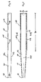
- FIG. 4 shows a preferred embodiment of a drawbar in side view
- Fig. 5 in top view.
- Fig. 5 there are hidden lines of the side wall panels and the lower chord with visible.
- 6 is a front view of the Section plane B-B outlined.
- the drawbar is constructed as a welded construction and contains in particular an upper chord OG, which laterally over the enclosed cross section and in particular its side walls SW protrudes and in particular in a fastening area facing away from the towing eye BA, in which devices for determining the drawbar relative to Chassis frame of a trailer are provided, protruding laterally Plate sections SP forms.
- the drawbar shows an in Longitudinal direction essentially constant width BZ, whereas it is in the longitudinal direction LR tapers to the front plate FP in front of the fastening area.
- the Side walls are preferably welded to a lower flange at the bottom.
- the Lower chord also shows lateral protrusions over the side wall panels, these projections but to the appropriate level for welding may be limited and in particular not the function and facilities to attach the drawbar.
- the plate sections SP on the top chord of the drawbar each have a front double row of holes offset in the longitudinal direction LHV and a rear double hole row LHH on which in the already described way of determining the drawbar in different Serve longitudinal positions with respect to the chassis frame.
- the plate section SP is advantageously at least twice the diameter of the holes in the rows of holes LHV, LHH.
- the protruding plate sections SP can by angle plates WB, which used in the outer angle of the upper chord OG and side walls SW, in particular are welded in, reinforced.
- the rows of holes LHV, LHH go then through the top chord and angle plates WB.
- the angle plates WB could, if necessary or appropriate, a material reinforcement along of the rows of holes also due to a greater thickness of the upper flange, however, too Loads of a higher overall weight, or through reinforcement elements placed on top be provided.
- the invention is not limited to the exemplary embodiments described, but can be modified in many ways within the scope of professional skills.
- the above and in the claims as well as the Drawable features are both individually and in different Combination can be advantageously implemented.
- the form of Drawbar and cross beams accessible in detail from a large number of variations.
Landscapes
- Engineering & Computer Science (AREA)
- Transportation (AREA)
- Mechanical Engineering (AREA)
- Body Structure For Vehicles (AREA)
- Fittings On The Vehicle Exterior For Carrying Loads, And Devices For Holding Or Mounting Articles (AREA)
- Supports For Plants (AREA)
- Connection Of Plates (AREA)
- Gripping On Spindles (AREA)
- Pressure Welding/Diffusion-Bonding (AREA)
- Mechanical Operated Clutches (AREA)
Applications Claiming Priority (2)
| Application Number | Priority Date | Filing Date | Title |
|---|---|---|---|
| DE10303338 | 2003-01-29 | ||
| DE10303338A DE10303338A1 (de) | 2003-01-29 | 2003-01-29 | Zugdeichselanordnung für Anhänger |
Publications (2)
| Publication Number | Publication Date |
|---|---|
| EP1442901A1 true EP1442901A1 (fr) | 2004-08-04 |
| EP1442901B1 EP1442901B1 (fr) | 2006-01-04 |
Family
ID=32603009
Family Applications (1)
| Application Number | Title | Priority Date | Filing Date |
|---|---|---|---|
| EP03028408A Expired - Lifetime EP1442901B1 (fr) | 2003-01-29 | 2003-12-11 | ensemble poutre de traction pour remorque |
Country Status (4)
| Country | Link |
|---|---|
| EP (1) | EP1442901B1 (fr) |
| AT (1) | ATE314941T1 (fr) |
| DE (2) | DE10303338A1 (fr) |
| ES (1) | ES2258199T3 (fr) |
Families Citing this family (1)
| Publication number | Priority date | Publication date | Assignee | Title |
|---|---|---|---|---|
| FR2948065B1 (fr) * | 2009-07-17 | 2015-01-09 | Ur Ben | Vehicule de transport apte a tracter une remorque |
Citations (7)
| Publication number | Priority date | Publication date | Assignee | Title |
|---|---|---|---|---|
| DE7320517U (de) * | 1973-06-01 | 1973-11-08 | Westfalia-Werke F Knoebel & Soehne Kg | Haltevorrichtung für eine Anhanger kupplung an Kraftfahrzeugen |
| DE9419710U1 (de) * | 1994-12-08 | 1995-01-26 | Knott GmbH, 83125 Eggstätt | Flanschkonstruktion insbesondere für Kraftfahrzeug-Anhänger |
| DE19648450A1 (de) * | 1995-11-23 | 1997-05-28 | Heinemann W Gmbh & Co Kg | Anhänger für Personenkraftwagen |
| EP0800936A1 (fr) * | 1996-04-12 | 1997-10-15 | BPW Bergische Achsen Kommanditgesellschaft | Dispositif de fixation pour un attelage de remorque |
| EP0950551A1 (fr) * | 1998-04-17 | 1999-10-20 | POMMIER & CIE | Agencement de traverse surbaissée pour accouplement d'une remorque sur un véhicule tracteur |
| DE19905676A1 (de) * | 1999-02-11 | 2000-08-31 | Bpw Bergische Achsen Kg | Zugdeichsel für Zentralachsanhänger |
| WO2001076896A1 (fr) * | 2000-04-11 | 2001-10-18 | Volvo Lastvagnar Ab | Poutre de traction |
Family Cites Families (6)
| Publication number | Priority date | Publication date | Assignee | Title |
|---|---|---|---|---|
| CH214752A (fr) * | 1939-08-26 | 1941-05-15 | Draize S A | Remorque. |
| FR1461451A (fr) * | 1965-07-30 | 1966-12-09 | Perfectionnement apporté aux remorques agraires par flèche réglable | |
| US4391562A (en) * | 1981-05-07 | 1983-07-05 | Hetzner Randall H | Adjustable trailer drawbar |
| DE3147837A1 (de) * | 1981-12-03 | 1983-06-16 | Karl Müller GmbH & Co KG Fahrzeugwerk, 7292 Baiersbronn | Anhaenger mit einer achse oder einer tandemachse |
| DE4301055A1 (de) * | 1993-01-16 | 1994-07-21 | Hoffmann Heinz Rainer Dr Ing | Zugdeichselanordnung |
| DE29911086U1 (de) * | 1999-06-25 | 1999-08-12 | WAP Fahrzeugbau GmbH, 33178 Borchen | Zugdeichsel |
-
2003
- 2003-01-29 DE DE10303338A patent/DE10303338A1/de not_active Withdrawn
- 2003-12-11 DE DE50302110T patent/DE50302110D1/de not_active Expired - Lifetime
- 2003-12-11 EP EP03028408A patent/EP1442901B1/fr not_active Expired - Lifetime
- 2003-12-11 ES ES03028408T patent/ES2258199T3/es not_active Expired - Lifetime
- 2003-12-11 AT AT03028408T patent/ATE314941T1/de active
Patent Citations (7)
| Publication number | Priority date | Publication date | Assignee | Title |
|---|---|---|---|---|
| DE7320517U (de) * | 1973-06-01 | 1973-11-08 | Westfalia-Werke F Knoebel & Soehne Kg | Haltevorrichtung für eine Anhanger kupplung an Kraftfahrzeugen |
| DE9419710U1 (de) * | 1994-12-08 | 1995-01-26 | Knott GmbH, 83125 Eggstätt | Flanschkonstruktion insbesondere für Kraftfahrzeug-Anhänger |
| DE19648450A1 (de) * | 1995-11-23 | 1997-05-28 | Heinemann W Gmbh & Co Kg | Anhänger für Personenkraftwagen |
| EP0800936A1 (fr) * | 1996-04-12 | 1997-10-15 | BPW Bergische Achsen Kommanditgesellschaft | Dispositif de fixation pour un attelage de remorque |
| EP0950551A1 (fr) * | 1998-04-17 | 1999-10-20 | POMMIER & CIE | Agencement de traverse surbaissée pour accouplement d'une remorque sur un véhicule tracteur |
| DE19905676A1 (de) * | 1999-02-11 | 2000-08-31 | Bpw Bergische Achsen Kg | Zugdeichsel für Zentralachsanhänger |
| WO2001076896A1 (fr) * | 2000-04-11 | 2001-10-18 | Volvo Lastvagnar Ab | Poutre de traction |
Also Published As
| Publication number | Publication date |
|---|---|
| ATE314941T1 (de) | 2006-02-15 |
| DE10303338A1 (de) | 2004-08-19 |
| ES2258199T3 (es) | 2006-08-16 |
| EP1442901B1 (fr) | 2006-01-04 |
| DE50302110D1 (de) | 2006-03-30 |
Similar Documents
| Publication | Publication Date | Title |
|---|---|---|
| DE602005004913T2 (de) | Anordnung für eine fahrzeugseitenverkleidung und fahrzeug mit einer solchen seitenverkleidung | |
| EP2896549B1 (fr) | Remorque, en particulier remorque de camion surbaissé | |
| DE102008036824A1 (de) | Querträger für ein Kraftfahrzeug | |
| DE19905676B4 (de) | Zugdeichsel für Zentralachsanhänger | |
| EP0867314B1 (fr) | Support d'appui d'essieu réglable en hauteur pour remorques de véhicule | |
| DE102011113875A1 (de) | Vorbauschnabel mit variablem Windverband zur Herstellung eines Brückenbauwerks | |
| DE60012362T3 (de) | Befestigungsvorrichtung einer sattelkupplung | |
| EP1442901B1 (fr) | ensemble poutre de traction pour remorque | |
| EP1108639B1 (fr) | Châssis pour remorque | |
| DE10040018A1 (de) | Verbesserte Befestigung einer Pritsche oder dergleichen auf einem Fahrzeugunterbau | |
| DE102007051630A1 (de) | Lastaufnahme für eine Hebebühne | |
| DE202008017495U1 (de) | Unterfahrschutzvorrichtung | |
| DE3934121A1 (de) | Gekroepfte zuggabel fuer mehrachsige, drehschemelgelenkte anhaengerfahrzeuge | |
| DE3535634C2 (fr) | ||
| EP0538893B1 (fr) | Sellette d'attelage pour véhicule semi-remorque | |
| EP0046200B1 (fr) | Appareil pour le travail de la terre monté sur tracteur | |
| DE20216236U1 (de) | Sockel für Geldautomaten | |
| EP1468901A2 (fr) | Engin à chenille à voie variable | |
| EP0393452A2 (fr) | Remorque pour un bateau | |
| DE102006013066A1 (de) | Fahrzeuganhängeranordnung mit einer Zugdeichselanordnung und Zugdeichselanordnung | |
| EP0479134B1 (fr) | Châssis pour véhicules à moteur ou remorques | |
| DE102021129218A1 (de) | Deichselanordnung für einen Fahrzeuganhänger sowie Fahrzeuganhänger mit einer solchen Deichselanordnung | |
| DE20307830U1 (de) | Fahrgestell für Betonmischer | |
| DE2805214A1 (de) | Selbstfahrende einrichtung mit landwirtschaftlichen geraeten | |
| DE102022112894A1 (de) | Fahrzeuganhänger |
Legal Events
| Date | Code | Title | Description |
|---|---|---|---|
| PUAI | Public reference made under article 153(3) epc to a published international application that has entered the european phase |
Free format text: ORIGINAL CODE: 0009012 |
|
| AK | Designated contracting states |
Kind code of ref document: A1 Designated state(s): AT BE BG CH CY CZ DE DK EE ES FI FR GB GR HU IE IT LI LU MC NL PT RO SE SI SK TR |
|
| AX | Request for extension of the european patent |
Extension state: AL LT LV MK |
|
| 17P | Request for examination filed |
Effective date: 20050204 |
|
| AKX | Designation fees paid |
Designated state(s): AT BE BG CH CY CZ DE DK EE ES FI FR GB GR HU IE IT LI LU MC NL PT RO SE SI SK TR |
|
| 17Q | First examination report despatched |
Effective date: 20050331 |
|
| GRAP | Despatch of communication of intention to grant a patent |
Free format text: ORIGINAL CODE: EPIDOSNIGR1 |
|
| GRAS | Grant fee paid |
Free format text: ORIGINAL CODE: EPIDOSNIGR3 |
|
| GRAA | (expected) grant |
Free format text: ORIGINAL CODE: 0009210 |
|
| AK | Designated contracting states |
Kind code of ref document: B1 Designated state(s): AT BE BG CH CY CZ DE DK EE ES FI FR GB GR HU IE IT LI LU MC NL PT RO SE SI SK TR |
|
| PG25 | Lapsed in a contracting state [announced via postgrant information from national office to epo] |
Ref country code: GB Free format text: LAPSE BECAUSE OF FAILURE TO SUBMIT A TRANSLATION OF THE DESCRIPTION OR TO PAY THE FEE WITHIN THE PRESCRIBED TIME-LIMIT Effective date: 20060104 Ref country code: IE Free format text: LAPSE BECAUSE OF FAILURE TO SUBMIT A TRANSLATION OF THE DESCRIPTION OR TO PAY THE FEE WITHIN THE PRESCRIBED TIME-LIMIT Effective date: 20060104 Ref country code: SI Free format text: LAPSE BECAUSE OF FAILURE TO SUBMIT A TRANSLATION OF THE DESCRIPTION OR TO PAY THE FEE WITHIN THE PRESCRIBED TIME-LIMIT Effective date: 20060104 Ref country code: FI Free format text: LAPSE BECAUSE OF FAILURE TO SUBMIT A TRANSLATION OF THE DESCRIPTION OR TO PAY THE FEE WITHIN THE PRESCRIBED TIME-LIMIT Effective date: 20060104 Ref country code: NL Free format text: LAPSE BECAUSE OF FAILURE TO SUBMIT A TRANSLATION OF THE DESCRIPTION OR TO PAY THE FEE WITHIN THE PRESCRIBED TIME-LIMIT Effective date: 20060104 |
|
| REG | Reference to a national code |
Ref country code: GB Ref legal event code: FG4D Free format text: NOT ENGLISH |
|
| REG | Reference to a national code |
Ref country code: CH Ref legal event code: EP |
|
| REG | Reference to a national code |
Ref country code: IE Ref legal event code: FG4D Free format text: LANGUAGE OF EP DOCUMENT: GERMAN |
|
| REG | Reference to a national code |
Ref country code: RO Ref legal event code: EPE |
|
| REF | Corresponds to: |
Ref document number: 50302110 Country of ref document: DE Date of ref document: 20060330 Kind code of ref document: P |
|
| PG25 | Lapsed in a contracting state [announced via postgrant information from national office to epo] |
Ref country code: DK Free format text: LAPSE BECAUSE OF FAILURE TO SUBMIT A TRANSLATION OF THE DESCRIPTION OR TO PAY THE FEE WITHIN THE PRESCRIBED TIME-LIMIT Effective date: 20060404 Ref country code: BG Free format text: LAPSE BECAUSE OF FAILURE TO SUBMIT A TRANSLATION OF THE DESCRIPTION OR TO PAY THE FEE WITHIN THE PRESCRIBED TIME-LIMIT Effective date: 20060404 Ref country code: SE Free format text: LAPSE BECAUSE OF FAILURE TO SUBMIT A TRANSLATION OF THE DESCRIPTION OR TO PAY THE FEE WITHIN THE PRESCRIBED TIME-LIMIT Effective date: 20060404 |
|
| REG | Reference to a national code |
Ref country code: HU Ref legal event code: AG4A Ref document number: E000238 Country of ref document: HU |
|
| REG | Reference to a national code |
Ref country code: GR Ref legal event code: EP Ref document number: 20060400936 Country of ref document: GR |
|
| NLV1 | Nl: lapsed or annulled due to failure to fulfill the requirements of art. 29p and 29m of the patents act | ||
| GBV | Gb: ep patent (uk) treated as always having been void in accordance with gb section 77(7)/1977 [no translation filed] |
Effective date: 20060104 |
|
| ET | Fr: translation filed | ||
| REG | Reference to a national code |
Ref country code: ES Ref legal event code: FG2A Ref document number: 2258199 Country of ref document: ES Kind code of ref document: T3 |
|
| REG | Reference to a national code |
Ref country code: IE Ref legal event code: FD4D |
|
| PLBE | No opposition filed within time limit |
Free format text: ORIGINAL CODE: 0009261 |
|
| STAA | Information on the status of an ep patent application or granted ep patent |
Free format text: STATUS: NO OPPOSITION FILED WITHIN TIME LIMIT |
|
| 26N | No opposition filed |
Effective date: 20061005 |
|
| PG25 | Lapsed in a contracting state [announced via postgrant information from national office to epo] |
Ref country code: MC Free format text: LAPSE BECAUSE OF NON-PAYMENT OF DUE FEES Effective date: 20061231 |
|
| PG25 | Lapsed in a contracting state [announced via postgrant information from national office to epo] |
Ref country code: CZ Free format text: LAPSE BECAUSE OF FAILURE TO SUBMIT A TRANSLATION OF THE DESCRIPTION OR TO PAY THE FEE WITHIN THE PRESCRIBED TIME-LIMIT Effective date: 20060104 |
|
| PG25 | Lapsed in a contracting state [announced via postgrant information from national office to epo] |
Ref country code: EE Free format text: LAPSE BECAUSE OF FAILURE TO SUBMIT A TRANSLATION OF THE DESCRIPTION OR TO PAY THE FEE WITHIN THE PRESCRIBED TIME-LIMIT Effective date: 20060104 |
|
| PG25 | Lapsed in a contracting state [announced via postgrant information from national office to epo] |
Ref country code: LU Free format text: LAPSE BECAUSE OF NON-PAYMENT OF DUE FEES Effective date: 20061211 Ref country code: TR Free format text: LAPSE BECAUSE OF FAILURE TO SUBMIT A TRANSLATION OF THE DESCRIPTION OR TO PAY THE FEE WITHIN THE PRESCRIBED TIME-LIMIT Effective date: 20060104 |
|
| REG | Reference to a national code |
Ref country code: CH Ref legal event code: PL |
|
| PG25 | Lapsed in a contracting state [announced via postgrant information from national office to epo] |
Ref country code: LI Free format text: LAPSE BECAUSE OF NON-PAYMENT OF DUE FEES Effective date: 20071231 Ref country code: CH Free format text: LAPSE BECAUSE OF NON-PAYMENT OF DUE FEES Effective date: 20071231 |
|
| PG25 | Lapsed in a contracting state [announced via postgrant information from national office to epo] |
Ref country code: CY Free format text: LAPSE BECAUSE OF FAILURE TO SUBMIT A TRANSLATION OF THE DESCRIPTION OR TO PAY THE FEE WITHIN THE PRESCRIBED TIME-LIMIT Effective date: 20060104 |
|
| REG | Reference to a national code |
Ref country code: DE Ref legal event code: R082 Ref document number: 50302110 Country of ref document: DE Representative=s name: GERHARD WEBER, DE |
|
| REG | Reference to a national code |
Ref country code: DE Ref legal event code: R082 Ref document number: 50302110 Country of ref document: DE Representative=s name: BAUR & WEBER PATENTANWAELTE PARTG MBB, DE Effective date: 20120402 Ref country code: DE Ref legal event code: R081 Ref document number: 50302110 Country of ref document: DE Owner name: SCHMITZ CARGOBULL GOTHA GMBH, DE Free format text: FORMER OWNER: SCHMITZ GOTHA FAHRZEUGWERKE GMBH, 99867 GOTHA, DE Effective date: 20120402 Ref country code: DE Ref legal event code: R082 Ref document number: 50302110 Country of ref document: DE Representative=s name: BAUR & WEBER PATENTANWAELTE, DE Effective date: 20120402 |
|
| REG | Reference to a national code |
Ref country code: DE Ref legal event code: R082 Ref document number: 50302110 Country of ref document: DE Representative=s name: BAUR & WEBER PATENTANWAELTE PARTG MBB, DE Ref country code: DE Ref legal event code: R082 Ref document number: 50302110 Country of ref document: DE Representative=s name: BAUR & WEBER PATENTANWAELTE, DE |
|
| REG | Reference to a national code |
Ref country code: FR Ref legal event code: PLFP Year of fee payment: 13 |
|
| PGFP | Annual fee paid to national office [announced via postgrant information from national office to epo] |
Ref country code: GR Payment date: 20151217 Year of fee payment: 13 |
|
| PGFP | Annual fee paid to national office [announced via postgrant information from national office to epo] |
Ref country code: HU Payment date: 20151201 Year of fee payment: 13 Ref country code: RO Payment date: 20151203 Year of fee payment: 13 Ref country code: SK Payment date: 20151201 Year of fee payment: 13 Ref country code: PT Payment date: 20151201 Year of fee payment: 13 |
|
| PGFP | Annual fee paid to national office [announced via postgrant information from national office to epo] |
Ref country code: IT Payment date: 20151222 Year of fee payment: 13 |
|
| REG | Reference to a national code |
Ref country code: FR Ref legal event code: PLFP Year of fee payment: 14 |
|
| PG25 | Lapsed in a contracting state [announced via postgrant information from national office to epo] |
Ref country code: RO Free format text: LAPSE BECAUSE OF NON-PAYMENT OF DUE FEES Effective date: 20161211 |
|
| PG25 | Lapsed in a contracting state [announced via postgrant information from national office to epo] |
Ref country code: PT Free format text: LAPSE BECAUSE OF NON-PAYMENT OF DUE FEES Effective date: 20170612 |
|
| REG | Reference to a national code |
Ref country code: SK Ref legal event code: MM4A Ref document number: E 438 Country of ref document: SK Effective date: 20161211 |
|
| PG25 | Lapsed in a contracting state [announced via postgrant information from national office to epo] |
Ref country code: SK Free format text: LAPSE BECAUSE OF NON-PAYMENT OF DUE FEES Effective date: 20161211 Ref country code: GR Free format text: LAPSE BECAUSE OF NON-PAYMENT OF DUE FEES Effective date: 20170707 Ref country code: IT Free format text: LAPSE BECAUSE OF NON-PAYMENT OF DUE FEES Effective date: 20161211 |
|
| PG25 | Lapsed in a contracting state [announced via postgrant information from national office to epo] |
Ref country code: HU Free format text: LAPSE BECAUSE OF NON-PAYMENT OF DUE FEES Effective date: 20161212 |
|
| REG | Reference to a national code |
Ref country code: FR Ref legal event code: PLFP Year of fee payment: 15 |
|
| PGFP | Annual fee paid to national office [announced via postgrant information from national office to epo] |
Ref country code: DE Payment date: 20211231 Year of fee payment: 19 Ref country code: AT Payment date: 20211216 Year of fee payment: 19 Ref country code: FR Payment date: 20211220 Year of fee payment: 19 |
|
| PGFP | Annual fee paid to national office [announced via postgrant information from national office to epo] |
Ref country code: BE Payment date: 20211217 Year of fee payment: 19 |
|
| PGFP | Annual fee paid to national office [announced via postgrant information from national office to epo] |
Ref country code: ES Payment date: 20220119 Year of fee payment: 19 |
|
| REG | Reference to a national code |
Ref country code: DE Ref legal event code: R119 Ref document number: 50302110 Country of ref document: DE |
|
| REG | Reference to a national code |
Ref country code: AT Ref legal event code: MM01 Ref document number: 314941 Country of ref document: AT Kind code of ref document: T Effective date: 20221211 |
|
| REG | Reference to a national code |
Ref country code: BE Ref legal event code: MM Effective date: 20221231 |
|
| PG25 | Lapsed in a contracting state [announced via postgrant information from national office to epo] |
Ref country code: DE Free format text: LAPSE BECAUSE OF NON-PAYMENT OF DUE FEES Effective date: 20230701 Ref country code: AT Free format text: LAPSE BECAUSE OF NON-PAYMENT OF DUE FEES Effective date: 20221211 |
|
| PG25 | Lapsed in a contracting state [announced via postgrant information from national office to epo] |
Ref country code: FR Free format text: LAPSE BECAUSE OF NON-PAYMENT OF DUE FEES Effective date: 20221231 Ref country code: BE Free format text: LAPSE BECAUSE OF NON-PAYMENT OF DUE FEES Effective date: 20221231 |
|
| REG | Reference to a national code |
Ref country code: ES Ref legal event code: FD2A Effective date: 20240126 |
|
| PG25 | Lapsed in a contracting state [announced via postgrant information from national office to epo] |
Ref country code: ES Free format text: LAPSE BECAUSE OF NON-PAYMENT OF DUE FEES Effective date: 20221212 |
|
| PG25 | Lapsed in a contracting state [announced via postgrant information from national office to epo] |
Ref country code: ES Free format text: LAPSE BECAUSE OF NON-PAYMENT OF DUE FEES Effective date: 20221212 |