EP1442851A1 - Stanz- und Rill-Gegendruckplatte und Verfahren zu deren Herstellung und Gebrauch sowie damit ausgestattete Maschine - Google Patents
Stanz- und Rill-Gegendruckplatte und Verfahren zu deren Herstellung und Gebrauch sowie damit ausgestattete Maschine Download PDFInfo
- Publication number
- EP1442851A1 EP1442851A1 EP03028539A EP03028539A EP1442851A1 EP 1442851 A1 EP1442851 A1 EP 1442851A1 EP 03028539 A EP03028539 A EP 03028539A EP 03028539 A EP03028539 A EP 03028539A EP 1442851 A1 EP1442851 A1 EP 1442851A1
- Authority
- EP
- European Patent Office
- Prior art keywords
- creasing
- punching
- pressure plate
- counter
- sheet
- Prior art date
- Legal status (The legal status is an assumption and is not a legal conclusion. Google has not performed a legal analysis and makes no representation as to the accuracy of the status listed.)
- Granted
Links
Images




Classifications
-
- B—PERFORMING OPERATIONS; TRANSPORTING
- B41—PRINTING; LINING MACHINES; TYPEWRITERS; STAMPS
- B41F—PRINTING MACHINES OR PRESSES
- B41F19/00—Apparatus or machines for carrying out printing operations combined with other operations
- B41F19/008—Apparatus or machines for carrying out printing operations combined with other operations with means for stamping or cutting out
-
- B—PERFORMING OPERATIONS; TRANSPORTING
- B23—MACHINE TOOLS; METAL-WORKING NOT OTHERWISE PROVIDED FOR
- B23P—METAL-WORKING NOT OTHERWISE PROVIDED FOR; COMBINED OPERATIONS; UNIVERSAL MACHINE TOOLS
- B23P15/00—Making specific metal objects by operations not covered by a single other subclass or a group in this subclass
- B23P15/28—Making specific metal objects by operations not covered by a single other subclass or a group in this subclass cutting tools
- B23P15/40—Making specific metal objects by operations not covered by a single other subclass or a group in this subclass cutting tools shearing tools
-
- B—PERFORMING OPERATIONS; TRANSPORTING
- B26—HAND CUTTING TOOLS; CUTTING; SEVERING
- B26D—CUTTING; DETAILS COMMON TO MACHINES FOR PERFORATING, PUNCHING, CUTTING-OUT, STAMPING-OUT OR SEVERING
- B26D7/00—Details of apparatus for cutting, cutting-out, stamping-out, punching, perforating, or severing by means other than cutting
- B26D7/20—Cutting beds
-
- B—PERFORMING OPERATIONS; TRANSPORTING
- B26—HAND CUTTING TOOLS; CUTTING; SEVERING
- B26F—PERFORATING; PUNCHING; CUTTING-OUT; STAMPING-OUT; SEVERING BY MEANS OTHER THAN CUTTING
- B26F1/00—Perforating; Punching; Cutting-out; Stamping-out; Apparatus therefor
- B26F1/38—Cutting-out; Stamping-out
- B26F1/44—Cutters therefor; Dies therefor
-
- B—PERFORMING OPERATIONS; TRANSPORTING
- B31—MAKING ARTICLES OF PAPER, CARDBOARD OR MATERIAL WORKED IN A MANNER ANALOGOUS TO PAPER; WORKING PAPER, CARDBOARD OR MATERIAL WORKED IN A MANNER ANALOGOUS TO PAPER
- B31F—MECHANICAL WORKING OR DEFORMATION OF PAPER, CARDBOARD OR MATERIAL WORKED IN A MANNER ANALOGOUS TO PAPER
- B31F1/00—Mechanical deformation without removing material, e.g. in combination with laminating
- B31F1/08—Creasing
- B31F1/10—Creasing by rotary tools
-
- B—PERFORMING OPERATIONS; TRANSPORTING
- B41—PRINTING; LINING MACHINES; TYPEWRITERS; STAMPS
- B41G—APPARATUS FOR BRONZE PRINTING, LINE PRINTING, OR FOR BORDERING OR EDGING SHEETS OR LIKE ARTICLES; AUXILIARY FOR PERFORATING IN CONJUNCTION WITH PRINTING
- B41G7/00—Auxiliary perforating apparatus associated with printing devices
-
- B—PERFORMING OPERATIONS; TRANSPORTING
- B26—HAND CUTTING TOOLS; CUTTING; SEVERING
- B26D—CUTTING; DETAILS COMMON TO MACHINES FOR PERFORATING, PUNCHING, CUTTING-OUT, STAMPING-OUT OR SEVERING
- B26D7/00—Details of apparatus for cutting, cutting-out, stamping-out, punching, perforating, or severing by means other than cutting
- B26D7/20—Cutting beds
- B26D2007/202—Rollers or cylinders being pivoted during operation
-
- B—PERFORMING OPERATIONS; TRANSPORTING
- B26—HAND CUTTING TOOLS; CUTTING; SEVERING
- B26F—PERFORATING; PUNCHING; CUTTING-OUT; STAMPING-OUT; SEVERING BY MEANS OTHER THAN CUTTING
- B26F1/00—Perforating; Punching; Cutting-out; Stamping-out; Apparatus therefor
- B26F1/38—Cutting-out; Stamping-out
- B26F1/44—Cutters therefor; Dies therefor
- B26F2001/4445—Matrices, female dies, creasing tools
-
- B—PERFORMING OPERATIONS; TRANSPORTING
- B31—MAKING ARTICLES OF PAPER, CARDBOARD OR MATERIAL WORKED IN A MANNER ANALOGOUS TO PAPER; WORKING PAPER, CARDBOARD OR MATERIAL WORKED IN A MANNER ANALOGOUS TO PAPER
- B31B—MAKING CONTAINERS OF PAPER, CARDBOARD OR MATERIAL WORKED IN A MANNER ANALOGOUS TO PAPER
- B31B50/00—Making rigid or semi-rigid containers, e.g. boxes or cartons
- B31B50/25—Surface scoring
- B31B50/254—Surface scoring using tools mounted on belts or chains
-
- B—PERFORMING OPERATIONS; TRANSPORTING
- B31—MAKING ARTICLES OF PAPER, CARDBOARD OR MATERIAL WORKED IN A MANNER ANALOGOUS TO PAPER; WORKING PAPER, CARDBOARD OR MATERIAL WORKED IN A MANNER ANALOGOUS TO PAPER
- B31B—MAKING CONTAINERS OF PAPER, CARDBOARD OR MATERIAL WORKED IN A MANNER ANALOGOUS TO PAPER
- B31B50/00—Making rigid or semi-rigid containers, e.g. boxes or cartons
- B31B50/25—Surface scoring
- B31B50/256—Surface scoring using tools mounted on a drum
Definitions
- the present invention relates to a stamping and creasing counter-pressure plate which a metal sheet is produced, according to the preamble of claim 1. Furthermore The invention relates to a method for producing a punching and creasing pressure plate from a metal sheet, according to the preamble of claim 5. The invention also relates to a machine for processing a Substrate, with a punching and creasing counter pressure plate, according to the generic term of Claim 9. Ultimately, the invention relates to a method for punching and Grooving of a printing material, according to the preamble of claim 10.
- punching includes both cutting with continuous cutting line as well as a cutting with regularly interrupted Cut line, i.e. a perforation, understood.
- Punching and creasing pressure plates are used as counterparts to punching and creasing tools together with these typically for the production of folding boxes used.
- a punching and creasing tool has both one of at least one raised punch line existing punch line structure as well as one of at least existing creasing line structure.
- a punching and creasing counter pressure plate has a creasing groove structure consisting of at least one creasing groove into which the material to be creased when creasing from the creasing line structure is pushed in.
- the punching and creasing counter pressure plate has a Surface in which the grooved structure is introduced and which is to be punched Support material on the back when punching.
- this steel sheet may be advantageous in terms of service life, but is in terms of the introduction of the creasing structure by milling and in terms of suitability for a rotary Punching and creasing are disadvantageous.
- Rotational punching and creasing is e.g. by means of the device described in DE 100 52 777 A1 and that Introducing the creasing-groove structure by milling is mentioned in DE 196 10 574 C1.).
- the invention has for its object, one for rotary punching and creasing suitable punching and creasing counter pressure plate and a machine equipped with it create an uncomplicated process for the production of this stamping and creasing pressure plate specify and specify a procedure by means of which also Stamping and creasing printing stock of great thickness.
- This task is carried out by a punching and creasing counter pressure plate with the characteristics of Claim 1, by a manufacturing method with the features of claim 5, a Printing substrate processing machine with the features of claim 9 and a punching Creasing method with the features of claim 10 solved.
- the punching and creasing counter-pressure plate according to the invention which is made of a metal sheet is produced, is characterized in that the metal sheet is an aluminum sheet.
- an aluminum or aluminum alloy e.g. B. AlMg 3 , AlMg, existing sheet metal understood. Since the aluminum sheet is much easier to lay or bend around a tool cylinder than a steel sheet with a sheet thickness comparable to the aluminum sheet, the punching and creasing counter-pressure plate according to the invention is very well suited for its use in rotary punching and creasing.
- the aluminum sheet has a hard anodized cover layer, the hardness of which is preferably at least 350 HV 0.05 (micro hardness test according to Vickers - see EN ISO 4516: 2002) and the thickness of which is preferably at least 10 micrometers is.
- This cover layer can be a very wear-resistant aluminum oxide layer (Al 2 O 3 ), the hardness of which is approximately constant over its layer thickness.
- the hard-anodized metal sheet that makes up the punching and creasing counter-pressure plate is not only resistant to the impact and pressure load exerted by the punching line (s) on the cover layer, but also to repeated bending and unfolding of the metal sheet Clamping and unclamping of the punching and creasing counter pressure plate on and from the tool cylinder is very resistant.
- the punching and creasing counter pressure plate maintains its shape stability over a long period of time. Due to the fact that the cover layer is formed from the metal sheet material by the oxidation of the aluminum, this cover layer is thus very firmly connected to the underlying base material, which is also referred to below as the support layer.
- the punching and creasing counter-pressure plate described here is a multi-layer plate, there is never any risk of the cover layer becoming detached from the carrier layer. This danger exists with other multi-layer punching and creasing counter-pressure plates of the prior art (cf. DE 195 38 538 C1), in which the cover layer and the carrier layer are formed separately from one another and only afterwards, e.g. B. by means of adhesive.
- the method according to the invention for producing a punching and creasing counter-pressure plate from a metal sheet is characterized in that as the metal sheet Aluminum sheet is used.
- the aluminum of this sheet can of course, as already indicated, a or more alloying elements improving the properties of the aluminum, e.g. B. Magnesium. In any case, it is advantageous that the aluminum or Machining its alloy to produce the creasing structure easier leaves when steel does.
- a cover layer with which the aluminum sheet according to a further development Hard anodizing can preferably be at most 150 micrometers and Z. B. at most 50 microns layer thickness very thin and difficult to machine Editing not noticeable.
- one or each creasing groove is so deep in that Inserted aluminum sheet so that the creasing groove covers the top layer completely and one underneath the backing layer lying only incompletely penetrates the top layer.
- the creasing structure which is only introduced into the aluminum sheet after hard anodizing does not go through the punching and creasing counter pressure plate in its entire thickness therethrough. Rather, at the bottom of the creasing structure z. B.
- the creasing structure has a bottom and is only open on one side.
- the floor is regarding one Use of the punching and creasing counter pressure plate as a cylinder lift is advantageous.
- To the Rotary punching and creasing must have the punching and creasing counter pressure plate on one Impression cylinders are clamped.
- the punching and creasing pressure plate When clamping the punching and creasing pressure plate the latter is subjected to bending and tensioning forces which reduce the risk pull that the punching and creasing counter pressure plate in the area to Counter pressure cylinder bulges grooves running axially parallel when these grooves as through holes, d. H. without the floor.
- the machine according to the invention for processing a printing material, with a punching and Creasing pressure plate is characterized in that this punching and creasing pressure plate formed as an aluminum sheet or made from such is.
- the machine containing the punching and creasing counterpressure plate according to the invention can a special machine that is used exclusively for off-line punching and creasing his.
- the machine can also be a printing machine that is next to at least one printing unit also includes a punching unit that is compatible with the invention Stamping and creasing pressure plate is equipped.
- Stamping and creasing pressure plate is equipped.
- Substrate within an in-line process e.g. B. First printed and then punched and grooved.
- the printing unit can be an offset printing unit or a z. B. as a coating unit be used flexographic printing unit.
- the method according to the invention for punching and creasing a printing material is thereby characterized that one for punching and creasing the printing material as a Aluminum sheet formed or manufactured from such a stamping and creasing counter-pressure plate and / or one equipped with this punching and creasing pressure plate Machine is used.
- This process can also be used to print comparatively thick substrates without any problems grooves because the aluminum sheet has a large groove depth due to its material properties the grooved structure allows and is still flexible.
- the flexibility of the aluminum sheet is advantageous in terms of further training, according to which the method is carried out as a rotary machining method at which the punching and creasing counter pressure plate together with the counter pressure cylinder, on which the punching and creasing counter-pressure plate is attached rotates.
- the one at The printing material used according to the invention for punching and creasing can be a Printing material web and is preferably a printing material sheet, for. B. a cardboard sheet for the production of folding boxes.
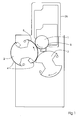
- FIG. 1 shows a machine 26 that processes sheet-like printing material 8.
- the machine 26 is a printing press and comprises a tool cylinder 1, one Impression cylinder 2 and a sheet transport cylinder 3, the impression cylinder 2 is viewed upstream in the sheet transport direction.
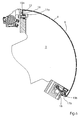
- On the tool cylinder 1 is one Stamping and creasing tool plate 5 magnetically attached and on the impression cylinder 2 at least one punching and creasing pressure plate 4 is attached.
- the punching and creasing counter-pressure plate 4 has at least one creasing groove 9 and a surface 27 into which the creasing groove 9 is introduced is on.
- the punching line 6 continues after it has cut through the substrate 8, on the surface 27 and presses the crease line 7 the printing material 8 simultaneously into the crease groove 9.
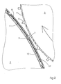
- FIG 3 is shown in a section that the two-layer punching and creasing counter-pressure plate 4 a comparatively hard cover layer which forms the surface 27 10, which has been produced by hard anodizing on a carrier layer 20 and consists of aluminum oxide.
- the cover layer 10 has an at least 350 HV 0.05 amount and preferably in a hardness range of 500 to 800 HV 0.05 Hardness and a minimum of 10 microns and preferably in one Thickness range from 20 to 50 microns lying top layer thickness d.
- the Backing layer 20 is comparatively soft and has a hardness range of 50 to 80 HB (Brinell hardness) lying hardness.
- the creasing line 7 has a creasing line height b that can be slightly higher than a punch line height a of the punch line 6, and a crease line width h, which is significantly smaller than a groove groove width g of the groove groove 9.
- the groove depth of the creasing groove 9 is less than the plate thickness f, so that the creasing groove 9 is one Has groove bottom with the floor thickness c, which is at least 0.1 millimeters.
- a Substrate thickness e of the substrate 8 is greater than 0.3 millimeters.
- the substrate 8 is a very thick cardboard sheet.
- the punching and creasing pressure plate 4 is off an aluminum sheet has been made by first producing it the top layer 10 made of aluminum oxide is hard anodized and then by an machining process, preferably milling, with the creasing groove 9 and others such creasing grooves has been provided. Since in Figure 3 only a narrowly limited Cutout is shown, this does not reveal that the two plates 4, 5 on the Circumferential surfaces of the two cylinders 1, 2 are located on these circumferential surfaces are curvilinearly curved.
- FIG. 5 A development of the punching and creasing tool plate 5 is shown in FIG has a front edge 11 and a side edge 12. From this settlement is the mentioned punching and creasing line structure for producing a folding box good seen.
- FIG. 5 a the punching and creasing counter-pressure plate 4 is in its counter-pressure cylinder 2 developed state shown.
- FIG. 5a shows clearly that the creasing groove structure in Figure 5a with the creasing lines 7 in Figure 4 in corresponds in a mirror-inverted manner.
- FIG. 5b is a section line Vb-Vb in FIG. 5a Cross-sectional view, from which serve as fastening hooks 15a, 15b at the front and rear plate end of the punching and creasing counter-pressure plate 4 can be seen are.
- FIGs 6 and 8 a holding and tensioning device is shown, which one front clamping device 17a for clamping the front bend 15a and one rear clamping device 17b for clamping the rear bevel 15b on Impression cylinder 2 includes.
- the rear clamping device 17b is on one lever-shaped, pivotable clamping element 18 is attached, by means of which the punching and Creasing pressure plate 4 on the impression cylinder 2 in the circumferential direction taut can be raised and tensioned.
- the front clamp 17a is a Stop 16 assigned to the side stop surface 14.
- With reference numeral 28 8 shows a cylinder circumferential direction immediately in front of the front clamping device 17a arranged gripper system for clamping the printing material 8.
- FIGS. 7, 9 and 10 show a positioning auxiliary device 19 with a Positioning ruler 25 shown, which over index pins 23, which at the ends of the Positioning auxiliary device 19 are attached for the purpose of positioning the Stamping and creasing tool plate 5 on the tool cylinder 1 with the latter at times can be put together.
- the tool cylinder 1 is at each of its ends with a circumferentially extending row of index holes 22 for the index pins 23 equipped.
- the function of the positioning auxiliary device 19 is as follows: After the positioning aid 19 in the desired Circumferential registers corresponding to selected one of the index holes 22 on the tool cylinder 1 is plugged to this axially parallel, the punching and creasing tool plate 5 with their front edge 11 evenly along the entire edge length to the positioning ruler 25 created. By subsequently moving the punching and creasing tool plate 5 along the positioning ruler 25, which is used here as a guide for the front edge 11 serves, in an end position, the side register of the punching and Tool plate 5 preset. The end position is due to the side edge 12 resting a side stop 21 of the positioning auxiliary device 19 is determined.
- the Tool cylinder 1 Only after the stamping and creasing counter pressure plate is countered over its entire plate surface pressed the tool cylinder 1, which is designed as a magnetic cylinder.
- the Tool cylinder 1 has a coated with a magnetically active material or preferably with magnets 24 (electric or preferably permanent magnets) occupied peripheral surface.
- the magnets 24 hold the punching and creasing tool plate 5 on the tool cylinder 1 in the register-accurate working position.
Landscapes
- Engineering & Computer Science (AREA)
- Mechanical Engineering (AREA)
- Life Sciences & Earth Sciences (AREA)
- Forests & Forestry (AREA)
- Perforating, Stamping-Out Or Severing By Means Other Than Cutting (AREA)
- Making Paper Articles (AREA)
- Printing Plates And Materials Therefor (AREA)
- Machines For Manufacturing Corrugated Board In Mechanical Paper-Making Processes (AREA)
Abstract
Description
- Figur 1
- eine Maschine mit einem Werkzeugzylinder zum Stanzen und Rillen und einem dem Werkzeugzylinder kooperativ zugeordneten Gegendruckzylinder,
- Figur 2
- den Werkzeugzylinder mit einer darauf befestigten Stanz- und Rill-Werkzeugplatte sowie den Gegendruckzylinder mit einer darauf befestigten Stanz- und Rill-Gegendruckplatte,
- Figur 3
- eine Stanz-Linie und eine Rill-Linie der Stanz- und Rill-Werkzeugplatte sowie eine Mehrschicht-Bauweise und eine Rill-Nut der Stanz- und Rill-Gegendruckplatte,
- Figur 4
- die Stanz- und Rill-Werkzeugplatte - abgenommen vom Werkzeugzylinder,
- Figuren 5a und 5b
- die Stanz- und Rill-Gegendruckplatte - abgenommen vom Gegendruckzylinder - in verschiedenen Ansichten,
- Figur 6
- eine Halte- und Spanneinrichtung des Gegendruckzylinders zum Halten und Spannen der Stanz- und Rill-Gegendruckplatte,
- Figur 7
- die genannten Zylinder und eine Positionierungs-Hilfseinrichtung zum Positionieren der Stanz- und Rill-Werkzeugplatte auf dem Werkzeugzylinder,
- Figur 8
- ein Greifersystem des Gegendruckzylinders zum Greifen eines Bedruckstoffbogens sowie ein Detail der Halte- und Spanneinrichtung,
- Figur 9
- die Positionierungs-Hilfseinrichtung in der Draufsicht sowie
- Figur 10
- den Werkzeugzylinder in der Draufsicht.
- 1
- Werkzeugzylinder
- 2
- Gegendruckzylinder
- 3
- Bogentransportzylinder
- 4
- Stanz- und Rill-Gegendruckplatte (Aluminiumblech)
- 5
- Stanz- und Rill-Werkzeugplatte
- 6
- Stanz-Linie
- 7
- Rill-Linie
- 8
- Bedruckstoff
- 9
- Rill-Nut
- 10
- Deckschicht
- 11
- Vorderkante
- 12
- Seitenkante
- 13
- Anschlagfläche (vordere)
- 14
- Anschlagfläche (seitliche)
- 15a
- Abkantung (vordere)
- 15b
- Abkantung (hintere)
- 16
- Anschlag
- 17a
- Klemmeinrichtung (vordere)
- 17b
- Klemmeinrichtung (hintere)
- 18
- Spannelement
- 19
- Positionierungs-Hilfseinrichtung
- 20
- Trägerschicht
- 21
- Seitenanschlag
- 22
- Registerloch
- 23
- Registerstift
- 24
- Magnet
- 25
- Positionierungs-Lineal
- 26
- Maschine
- 27
- Oberfläche
- 28
- Greifersystem
- a
- Stanz-Linien-Höhe
- b
- Rill-Linien-Höhe
- c
- Boden-Dicke
- d
- Deckschicht-Dicke
- e
- Bedruckstoff-Dicke
- f
- Platten-Dicke
- g
- Rill-Nuten-Breite
- h
- Rill-Linien-Breite
Claims (12)
- Stanz- und Rill-Gegendruckplatte (4), die aus einem Metallblech hergestellt ist,
dadurch gekennzeichnet, dass das Metallblech ein Aluminiumblech (4) ist. - Stanz- und Rill-Gegendruckplatte (4) nach Anspruch 1,
dadurch gekennzeichnet, dass das Aluminiumblech (4) eine hartanodisierte Deckschicht (10) aufweist. - Stanz- und Rill-Gegendruckplatte (4) nach Anspruch 2,
dadurch gekennzeichnet, dass die Härte der Deckschicht (10) mindestens 350 HV 0,05 beträgt. - Stanz- und Rill-Gegendruckplatte (4) nach Anspruch 2 oder 3,
dadurch gekennzeichnet, dass die Dicke (d) der Deckschicht (10) mindestens 10 µm beträgt. - Verfahren zur Herstellung einer Stanz- und Rill-Gegendruckplatte (4) aus einem Metallblech,
dadurch gekennzeichnet, dass ein Aluminiumblech (4) als das Metallblech verwendet wird. - Verfahren nach Anspruch 5,
dadurch gekennzeichnet, dass das Aluminiumblech (4) durch Hartanodisieren mit einer Deckschicht (10) versehen wird. - Verfahren nach Anspruch 6,
dadurch gekennzeichnet, dass eine Rill-Nut (9) so tief in das Aluminiumblech (4) eingebracht wird, dass die Rill-Nut (9) die Deckschicht (10) vollständig und eine unter der Deckschicht (10) liegende Trägerschicht (20) nur unvollständig durchdringt. - Verfahren nach Anspruch 6 oder 7,
dadurch gekennzeichnet, dass eine/die Rill-Nut (9) durch Fräsen in das Aluminiumblech (4) eingebracht wird. - Maschine (26) zum Bearbeiten eines Bedruckstoffs (8), mit einer Stanz- und Rill-Gegendruckplatte (4),
dadurch gekennzeichnet, dass die Stanz- und Rill-Gegendruckplatte (4) nach einem der Ansprüche 1 bis 4 ausgebildet und/oder einem der Ansprüche 5 bis 8 hergestellt ist. - Verfahren zum Stanzen und Rillen eines Bedruckstoffs (8),
dadurch gekennzeichnet, dass zum Stanzen und Rillen des Bedruckstoffs (8) eine nach einem der Ansprüche 1 bis 4 ausgebildete und/oder einem der Ansprüche 5 bis 8 hergestellte Stanz- und Rill-Gegendruckplatte (4) und/oder eine nach einem der Ansprüche 9 bis 11 ausgebildete Maschine (26) verwendet wird. - Verfahren nach Anspruch 10,
dadurch gekennzeichnet, dass es als ein rotatives Bearbeitungsverfahren ausgeführt wird, bei welchem die Stanz- und Rill-Gegendruckplatte (4) rotiert. - Verfahren nach Anspruch 10 oder 11,
dadurch gekennzeichnet, dass als der Bedruckstoff (8) ein Bedruckstoffbogen verwendet wird.
Applications Claiming Priority (2)
| Application Number | Priority Date | Filing Date | Title |
|---|---|---|---|
| DE10303178 | 2003-01-28 | ||
| DE10303178A DE10303178A1 (de) | 2003-01-28 | 2003-01-28 | Stanz- und Rill-Gegendruckplatte und Verfahren zu deren Herstellung und Gebrauch sowie damit ausgestattete Maschine |
Publications (2)
| Publication Number | Publication Date |
|---|---|
| EP1442851A1 true EP1442851A1 (de) | 2004-08-04 |
| EP1442851B1 EP1442851B1 (de) | 2005-10-12 |
Family
ID=32602979
Family Applications (1)
| Application Number | Title | Priority Date | Filing Date |
|---|---|---|---|
| EP03028539A Expired - Lifetime EP1442851B1 (de) | 2003-01-28 | 2003-12-11 | Stanz- und Rill-Gegendruckplatte und Verfahren zu deren Herstellung und Gebrauch sowie damit ausgestattete Maschine |
Country Status (5)
| Country | Link |
|---|---|
| US (1) | US20040214703A1 (de) |
| EP (1) | EP1442851B1 (de) |
| JP (1) | JP4699700B2 (de) |
| AT (1) | ATE306377T1 (de) |
| DE (2) | DE10303178A1 (de) |
Cited By (2)
| Publication number | Priority date | Publication date | Assignee | Title |
|---|---|---|---|---|
| EP2027993A1 (de) * | 2007-08-23 | 2009-02-25 | Boegli-Gravures S.A. | Vorrichtung zur Vorbereitung von Verpackungspapier auf den anschliessenden Verpackungsprozess |
| CN109732274A (zh) * | 2018-11-16 | 2019-05-10 | 中国航发西安动力控制科技有限公司 | 带硬脆性膜层的衬套孔口密封边的加工方法 |
Families Citing this family (21)
| Publication number | Priority date | Publication date | Assignee | Title |
|---|---|---|---|---|
| DE102005056036B4 (de) * | 2004-11-26 | 2010-11-11 | Ebe Hesterman | Vorrichtung zum veredelnden Bearbeiten von bogenförmigen Substraten |
| US7565856B2 (en) * | 2005-07-01 | 2009-07-28 | Eagle Rotary Systems, Inc. | Rotary cutting tool |
| JP2007320025A (ja) * | 2006-05-02 | 2007-12-13 | Komori Corp | 処理装置 |
| JP2011031515A (ja) * | 2009-08-03 | 2011-02-17 | Nippon Die Steel Kk | 罫入れ装置および罫入れ装置におけるカウンタプレート |
| EP3243615B1 (de) | 2011-11-10 | 2020-01-08 | Packsize LLC | Hohe konvertiermaschine zum umwandeln von materialien in verpackungsvorlagen |
| DE102011122146B4 (de) * | 2011-12-22 | 2013-10-31 | Klaus Borker | Verfahren zur Aufbereitung eines Magnet- oder Druckzylinders einer Stanz- oder Druckmaschine und durch das Verfahren aufbereiteter Magnet- oder Druckzylinder |
| US10093438B2 (en) | 2014-12-29 | 2018-10-09 | Packsize Llc | Converting machine |
| DE102016223226B4 (de) * | 2015-11-23 | 2025-05-08 | Koenig & Bauer Ag | Vorrichtung zum Behandeln von Substraten |
| ITUA20162806A1 (it) * | 2016-04-21 | 2017-10-21 | Sei S P A | Procedimento e dispositivo per la preparazione di piastre per cilindri per la cordonatura di articoli di cartotecnica. |
| ITUA20163886A1 (it) * | 2016-05-27 | 2017-11-27 | Smurfit Kappa Italia S P A | Fustella a cordonatore multiplo |
| US10850469B2 (en) | 2016-06-16 | 2020-12-01 | Packsize Llc | Box forming machine |
| CN109311256B (zh) | 2016-06-16 | 2021-06-22 | 派克赛泽有限责任公司 | 箱模板生产系统和方法 |
| US11242214B2 (en) | 2017-01-18 | 2022-02-08 | Packsize Llc | Converting machine with fold sensing mechanism |
| SE1750727A1 (sv) | 2017-06-08 | 2018-10-09 | Packsize Llc | Tool head positioning mechanism for a converting machine, and method for positioning a plurality of tool heads in a converting machine |
| WO2019007552A1 (en) | 2017-07-06 | 2019-01-10 | Bobst Mex Sa | RAINING MACHINE, GROOVING CYLINDER FOR RAINING MACHINE, AND METHOD FOR RAINING SHEETS |
| US11565493B2 (en) * | 2017-07-06 | 2023-01-31 | Bobst Mex Sa | Method of creasing sheets |
| US11305903B2 (en) | 2018-04-05 | 2022-04-19 | Avercon BVBA | Box template folding process and mechanisms |
| US11247427B2 (en) | 2018-04-05 | 2022-02-15 | Avercon BVBA | Packaging machine infeed, separation, and creasing mechanisms |
| US11634244B2 (en) | 2018-06-21 | 2023-04-25 | Packsize Llc | Packaging machine and systems |
| WO2021014192A1 (en) * | 2019-07-22 | 2021-01-28 | Sei S.P.A. | Process and device for preparing plates for cylinders to treat items of the paper processing industry |
| DE102022108914A1 (de) | 2022-04-12 | 2023-10-12 | Koenig & Bauer Ag | Vorrichtung zum Positionieren eines Werkzeugs und Substratbogen verarbeitende Maschine und Verfahren zum Positionieren eines Werkzeugs |
Citations (3)
| Publication number | Priority date | Publication date | Assignee | Title |
|---|---|---|---|---|
| US3847036A (en) * | 1973-10-10 | 1974-11-12 | Centenary Central | Method of producing cutting plates for die cutting operations |
| US4100844A (en) * | 1975-06-23 | 1978-07-18 | R & S Stanzformen Gmbh | Box blank punching tool |
| EP0323673A1 (de) * | 1987-12-29 | 1989-07-12 | Walker Scientific Europe B.V. | Vorrichtung und Verfahren zum Stanzen einer Folie oder von solchem bahnähnlichen Material |
Family Cites Families (23)
| Publication number | Priority date | Publication date | Assignee | Title |
|---|---|---|---|---|
| US3375762A (en) * | 1965-11-22 | 1968-04-02 | Harris Intertype Corp | Cutting and/or creasing apparatus |
| US3383991A (en) * | 1965-12-06 | 1968-05-21 | Harris Intertype Corp | Sheet material forming apparatus |
| US3650006A (en) * | 1968-12-11 | 1972-03-21 | American Can Co | Score manufacture |
| JPS59180832A (ja) * | 1983-03-31 | 1984-10-15 | Nippon Light Metal Co Ltd | 磁気記録材用アルマイト基板 |
| US4596541A (en) * | 1983-09-09 | 1986-06-24 | The Ward Machinery Company | Slit-score method and apparatus |
| US4761197A (en) * | 1986-07-28 | 1988-08-02 | Baxter Travenol Laboratories, Inc. | Apparatus for sealing a web of film |
| US4862799A (en) * | 1987-11-13 | 1989-09-05 | Rockwell International Corporation | Copper coated anodized aluminum ink metering roller |
| DE3929415A1 (de) * | 1989-09-05 | 1991-03-07 | Marbach Gmbh Karl | Stanz - rillplatte |
| JPH03246000A (ja) * | 1990-02-21 | 1991-11-01 | Nippon Tungsten Co Ltd | ダイカットブレード |
| DE4205276A1 (de) * | 1992-02-21 | 1993-08-26 | Roland Man Druckmasch | Vorrichtung zum aufspannen einer druckplatte auf einen plattenzylinder |
| JPH0724600U (ja) * | 1993-10-01 | 1995-05-09 | 三菱樹脂株式会社 | 合成樹脂シートの打抜き用面板 |
| NO311560B1 (no) * | 1996-02-16 | 2001-12-10 | Marbach Gmbh Karl | Fremgangsmåte til fremstilling av rillede, stansede deler fra en materialplate |
| DE19610574C5 (de) * | 1996-02-16 | 2004-11-18 | Cetex Ingenieurgesellschaft für Maschinenbau mbH | Verfahren und Stanz- und Rillwerkzeug zur Herstellung von gerillten Stanzteilen |
| JPH1177586A (ja) * | 1997-09-04 | 1999-03-23 | Mitsubishi Heavy Ind Ltd | ロータリカットオフ装置 |
| JPH1177598A (ja) * | 1997-09-02 | 1999-03-23 | Isowa Corp | アンビルシリンダの鋼板取付構造 |
| JPH11156798A (ja) * | 1997-11-21 | 1999-06-15 | Isowa Corp | シート材料のダイ |
| JPH11156796A (ja) * | 1997-11-25 | 1999-06-15 | Isowa Corp | シート材料の打抜き方法および装置 |
| FR2771958B1 (fr) * | 1997-12-08 | 2000-02-25 | Heidelberger Druckmasch Ag | Dispositif de coupe transversale de bandes de matiere et plieuse avec ou sans pointure comportant un tel dispositif de coupe |
| DE19814966C2 (de) * | 1998-04-03 | 2000-03-09 | Friedrich Eicher | Vorrichtung zum Perforieren, Rillen oder Stanzen für Ein- oder Mehrfarben-Bogenrotationsdruckmaschinen |
| US6138490A (en) * | 1998-07-17 | 2000-10-31 | Pechiney Rolled Products Llc | Process for rendering a metal sheet suitable for lighting applications and sheet produced thereby |
| DE10052777A1 (de) * | 2000-10-25 | 2002-05-08 | Koenig & Bauer Ag | Einrichtung zum Perforieren, Stanzen und/oder Rillen in einer Bogenoffsetmaschine |
| US6772663B2 (en) * | 2001-04-20 | 2004-08-10 | Tamarack Products, Inc. | Apparatus and method for rotary pressure cutting |
| US20030045412A1 (en) * | 2001-07-13 | 2003-03-06 | Schulz Galyn A. | Laser engraved embossing roll with wear-resistant coatings and method of making them |
-
2003
- 2003-01-28 DE DE10303178A patent/DE10303178A1/de not_active Withdrawn
- 2003-12-11 DE DE50301352T patent/DE50301352D1/de not_active Expired - Lifetime
- 2003-12-11 EP EP03028539A patent/EP1442851B1/de not_active Expired - Lifetime
- 2003-12-11 AT AT03028539T patent/ATE306377T1/de not_active IP Right Cessation
-
2004
- 2004-01-26 JP JP2004017111A patent/JP4699700B2/ja not_active Expired - Fee Related
- 2004-01-28 US US10/766,593 patent/US20040214703A1/en not_active Abandoned
Patent Citations (3)
| Publication number | Priority date | Publication date | Assignee | Title |
|---|---|---|---|---|
| US3847036A (en) * | 1973-10-10 | 1974-11-12 | Centenary Central | Method of producing cutting plates for die cutting operations |
| US4100844A (en) * | 1975-06-23 | 1978-07-18 | R & S Stanzformen Gmbh | Box blank punching tool |
| EP0323673A1 (de) * | 1987-12-29 | 1989-07-12 | Walker Scientific Europe B.V. | Vorrichtung und Verfahren zum Stanzen einer Folie oder von solchem bahnähnlichen Material |
Cited By (3)
| Publication number | Priority date | Publication date | Assignee | Title |
|---|---|---|---|---|
| EP2027993A1 (de) * | 2007-08-23 | 2009-02-25 | Boegli-Gravures S.A. | Vorrichtung zur Vorbereitung von Verpackungspapier auf den anschliessenden Verpackungsprozess |
| US9180643B2 (en) | 2007-08-23 | 2015-11-10 | Boegli-Gravures S.A. | Device for the treatment of packaging foils |
| CN109732274A (zh) * | 2018-11-16 | 2019-05-10 | 中国航发西安动力控制科技有限公司 | 带硬脆性膜层的衬套孔口密封边的加工方法 |
Also Published As
| Publication number | Publication date |
|---|---|
| ATE306377T1 (de) | 2005-10-15 |
| JP2004230547A (ja) | 2004-08-19 |
| JP4699700B2 (ja) | 2011-06-15 |
| EP1442851B1 (de) | 2005-10-12 |
| DE50301352D1 (de) | 2006-02-23 |
| DE10303178A1 (de) | 2004-07-29 |
| US20040214703A1 (en) | 2004-10-28 |
Similar Documents
| Publication | Publication Date | Title |
|---|---|---|
| EP1442851B1 (de) | Stanz- und Rill-Gegendruckplatte und Verfahren zu deren Herstellung und Gebrauch sowie damit ausgestattete Maschine | |
| DE60204941T2 (de) | Keilverriegelbare abnehmbare stanz- und matrizenbuchse in haltevorrichtung | |
| DE69521720T2 (de) | Mehrzweckrotationsstanzsystem | |
| DE102008017728B4 (de) | Verfahren zur Materialflusssteuerung beim Tiefziehen eines Werkstücks | |
| EP3418066A1 (de) | Verfahren zur herstellung eines prägewerkzeugs für taktil erfassbare strukturen | |
| WO2007093330A2 (de) | Verfahren und vorrichtungen zur herstellung von braille-prägeprofilen und von brailleschrift-prägungen sowie braille-prägeprofile als solche | |
| DE3318144A1 (de) | Vorrichtung zur herstellung von matrizen fuer eine tiegelpresse | |
| DE102009034437A1 (de) | Vorrichtung und Verfahren zur Ausbildung einer Kontur in einem Kartenkörper für einen tragbaren Datenträger, insbesondere für eine Chipkarte | |
| EP1843899A1 (de) | Prägewerkzeug in einem druckwerk, mit matrize und patrize | |
| EP1335825B1 (de) | Stanzvorrichtung | |
| EP3441233A1 (de) | Prägewerkzeug für taktil erfassbare strukturen | |
| WO2019145115A1 (de) | Vorrichtung zum befestigen eines prägewerkzeugs auf einer prägewalze | |
| EP0739731B1 (de) | Gegendruckvorrichtung für die Durchführung von Perforationen und/oder Stanzungen an Offset-Bogenmaschinen | |
| DE69707182T2 (de) | Verfahren zum Zurichten van Stanzwerkzeugen, sowie mit einem solchen Zurichtbogen ausgerüstete Stanzmaschine | |
| DE69708777T2 (de) | Verfahren zum Ausschneiden eines Zuschnittteils aus einer Blechplatte | |
| DE102011009523A1 (de) | Werkzeugträgeranordnung an einem Magnetzylinder einer Rotationsstanzeinrichtung sowie Werkzeugträger | |
| EP0596390B1 (de) | Matrizenbogen für ein Stanzwerkzeug zum Herstellen von Kartonagezuschnitten | |
| DE102006003037A1 (de) | Prägen in einem Druckwerk | |
| DE102007031001A1 (de) | Bogenrotationsdruckmaschine | |
| DE60304362T2 (de) | Tiefdruckplatte | |
| DE102006014383A1 (de) | Folienmatrize zur Anordnung an einer rotierend antreibbaren Prägewalze, Verfahren zu deren Herstellung sowie Verwendung eines flächigen Rohmaterials zu deren Herstellung | |
| EP1022134A1 (de) | Verfahren und Vorrichtung zum Erzeugen eines Prägedrucks | |
| WO2005007316A1 (de) | Verfahren und vorrichtung zur bearbeitung von randbereichen von zylindrischen hohlkörpern | |
| DE10328802A1 (de) | Vorrichtung zum Einfügen einer Plattenkante einer Druckplatte | |
| DE102021100374B3 (de) | Stanzvorrichtung, insbesondere Flachbettstanzvorrichtung, zum Stanzen von flächigen Stanzgütern |
Legal Events
| Date | Code | Title | Description |
|---|---|---|---|
| PUAI | Public reference made under article 153(3) epc to a published international application that has entered the european phase |
Free format text: ORIGINAL CODE: 0009012 |
|
| 17P | Request for examination filed |
Effective date: 20040430 |
|
| AK | Designated contracting states |
Kind code of ref document: A1 Designated state(s): AT BE BG CH CY CZ DE DK EE ES FI FR GB GR HU IE IT LI LU MC NL PT RO SE SI SK TR |
|
| AX | Request for extension of the european patent |
Extension state: AL LT LV MK |
|
| GRAP | Despatch of communication of intention to grant a patent |
Free format text: ORIGINAL CODE: EPIDOSNIGR1 |
|
| 17Q | First examination report despatched |
Effective date: 20050314 |
|
| AKX | Designation fees paid |
Designated state(s): AT BE BG CH CY CZ DE DK EE ES FI FR GB GR HU IE IT LI LU MC NL PT RO SE SI SK TR |
|
| GRAS | Grant fee paid |
Free format text: ORIGINAL CODE: EPIDOSNIGR3 |
|
| GRAA | (expected) grant |
Free format text: ORIGINAL CODE: 0009210 |
|
| AK | Designated contracting states |
Kind code of ref document: B1 Designated state(s): AT BE BG CH CY CZ DE DK EE ES FI FR GB GR HU IE IT LI LU MC NL PT RO SE SI SK TR |
|
| PG25 | Lapsed in a contracting state [announced via postgrant information from national office to epo] |
Ref country code: IT Free format text: LAPSE BECAUSE OF FAILURE TO SUBMIT A TRANSLATION OF THE DESCRIPTION OR TO PAY THE FEE WITHIN THE PRESCRIBED TIME-LIMIT;WARNING: LAPSES OF ITALIAN PATENTS WITH EFFECTIVE DATE BEFORE 2007 MAY HAVE OCCURRED AT ANY TIME BEFORE 2007. THE CORRECT EFFECTIVE DATE MAY BE DIFFERENT FROM THE ONE RECORDED. Effective date: 20051012 Ref country code: SI Free format text: LAPSE BECAUSE OF FAILURE TO SUBMIT A TRANSLATION OF THE DESCRIPTION OR TO PAY THE FEE WITHIN THE PRESCRIBED TIME-LIMIT Effective date: 20051012 Ref country code: IE Free format text: LAPSE BECAUSE OF FAILURE TO SUBMIT A TRANSLATION OF THE DESCRIPTION OR TO PAY THE FEE WITHIN THE PRESCRIBED TIME-LIMIT Effective date: 20051012 Ref country code: FI Free format text: LAPSE BECAUSE OF FAILURE TO SUBMIT A TRANSLATION OF THE DESCRIPTION OR TO PAY THE FEE WITHIN THE PRESCRIBED TIME-LIMIT Effective date: 20051012 Ref country code: NL Free format text: LAPSE BECAUSE OF FAILURE TO SUBMIT A TRANSLATION OF THE DESCRIPTION OR TO PAY THE FEE WITHIN THE PRESCRIBED TIME-LIMIT Effective date: 20051012 Ref country code: SK Free format text: LAPSE BECAUSE OF FAILURE TO SUBMIT A TRANSLATION OF THE DESCRIPTION OR TO PAY THE FEE WITHIN THE PRESCRIBED TIME-LIMIT Effective date: 20051012 Ref country code: TR Free format text: LAPSE BECAUSE OF FAILURE TO SUBMIT A TRANSLATION OF THE DESCRIPTION OR TO PAY THE FEE WITHIN THE PRESCRIBED TIME-LIMIT Effective date: 20051012 Ref country code: CZ Free format text: LAPSE BECAUSE OF FAILURE TO SUBMIT A TRANSLATION OF THE DESCRIPTION OR TO PAY THE FEE WITHIN THE PRESCRIBED TIME-LIMIT Effective date: 20051012 Ref country code: RO Free format text: LAPSE BECAUSE OF FAILURE TO SUBMIT A TRANSLATION OF THE DESCRIPTION OR TO PAY THE FEE WITHIN THE PRESCRIBED TIME-LIMIT Effective date: 20051012 Ref country code: EE Free format text: LAPSE BECAUSE OF FAILURE TO SUBMIT A TRANSLATION OF THE DESCRIPTION OR TO PAY THE FEE WITHIN THE PRESCRIBED TIME-LIMIT Effective date: 20051012 |
|
| REG | Reference to a national code |
Ref country code: GB Ref legal event code: FG4D Free format text: NOT ENGLISH |
|
| REG | Reference to a national code |
Ref country code: CH Ref legal event code: EP |
|
| REG | Reference to a national code |
Ref country code: IE Ref legal event code: FG4D Free format text: LANGUAGE OF EP DOCUMENT: GERMAN |
|
| PG25 | Lapsed in a contracting state [announced via postgrant information from national office to epo] |
Ref country code: AT Free format text: LAPSE BECAUSE OF NON-PAYMENT OF DUE FEES Effective date: 20051211 Ref country code: CY Free format text: LAPSE BECAUSE OF FAILURE TO SUBMIT A TRANSLATION OF THE DESCRIPTION OR TO PAY THE FEE WITHIN THE PRESCRIBED TIME-LIMIT Effective date: 20051211 |
|
| PG25 | Lapsed in a contracting state [announced via postgrant information from national office to epo] |
Ref country code: LU Free format text: LAPSE BECAUSE OF NON-PAYMENT OF DUE FEES Effective date: 20051231 Ref country code: BE Free format text: LAPSE BECAUSE OF NON-PAYMENT OF DUE FEES Effective date: 20051231 Ref country code: MC Free format text: LAPSE BECAUSE OF NON-PAYMENT OF DUE FEES Effective date: 20051231 |
|
| PG25 | Lapsed in a contracting state [announced via postgrant information from national office to epo] |
Ref country code: BG Free format text: LAPSE BECAUSE OF FAILURE TO SUBMIT A TRANSLATION OF THE DESCRIPTION OR TO PAY THE FEE WITHIN THE PRESCRIBED TIME-LIMIT Effective date: 20060112 Ref country code: SE Free format text: LAPSE BECAUSE OF FAILURE TO SUBMIT A TRANSLATION OF THE DESCRIPTION OR TO PAY THE FEE WITHIN THE PRESCRIBED TIME-LIMIT Effective date: 20060112 Ref country code: DK Free format text: LAPSE BECAUSE OF FAILURE TO SUBMIT A TRANSLATION OF THE DESCRIPTION OR TO PAY THE FEE WITHIN THE PRESCRIBED TIME-LIMIT Effective date: 20060112 Ref country code: GR Free format text: LAPSE BECAUSE OF FAILURE TO SUBMIT A TRANSLATION OF THE DESCRIPTION OR TO PAY THE FEE WITHIN THE PRESCRIBED TIME-LIMIT Effective date: 20060112 |
|
| PG25 | Lapsed in a contracting state [announced via postgrant information from national office to epo] |
Ref country code: ES Free format text: LAPSE BECAUSE OF FAILURE TO SUBMIT A TRANSLATION OF THE DESCRIPTION OR TO PAY THE FEE WITHIN THE PRESCRIBED TIME-LIMIT Effective date: 20060123 |
|
| GBT | Gb: translation of ep patent filed (gb section 77(6)(a)/1977) |
Effective date: 20060130 |
|
| REF | Corresponds to: |
Ref document number: 50301352 Country of ref document: DE Date of ref document: 20060223 Kind code of ref document: P |
|
| PG25 | Lapsed in a contracting state [announced via postgrant information from national office to epo] |
Ref country code: PT Free format text: LAPSE BECAUSE OF FAILURE TO SUBMIT A TRANSLATION OF THE DESCRIPTION OR TO PAY THE FEE WITHIN THE PRESCRIBED TIME-LIMIT Effective date: 20060313 |
|
| NLV1 | Nl: lapsed or annulled due to failure to fulfill the requirements of art. 29p and 29m of the patents act | ||
| PG25 | Lapsed in a contracting state [announced via postgrant information from national office to epo] |
Ref country code: HU Free format text: LAPSE BECAUSE OF FAILURE TO SUBMIT A TRANSLATION OF THE DESCRIPTION OR TO PAY THE FEE WITHIN THE PRESCRIBED TIME-LIMIT Effective date: 20060413 |
|
| REG | Reference to a national code |
Ref country code: IE Ref legal event code: FD4D |
|
| ET | Fr: translation filed | ||
| PLBE | No opposition filed within time limit |
Free format text: ORIGINAL CODE: 0009261 |
|
| STAA | Information on the status of an ep patent application or granted ep patent |
Free format text: STATUS: NO OPPOSITION FILED WITHIN TIME LIMIT |
|
| 26N | No opposition filed |
Effective date: 20060713 |
|
| BERE | Be: lapsed |
Owner name: HEIDELBERGER DRUCKMASCHINEN A.G. Effective date: 20051231 |
|
| REG | Reference to a national code |
Ref country code: FR Ref legal event code: PLFP Year of fee payment: 13 |
|
| REG | Reference to a national code |
Ref country code: FR Ref legal event code: PLFP Year of fee payment: 14 |
|
| PGFP | Annual fee paid to national office [announced via postgrant information from national office to epo] |
Ref country code: CH Payment date: 20161222 Year of fee payment: 14 Ref country code: GB Payment date: 20161222 Year of fee payment: 14 |
|
| PGFP | Annual fee paid to national office [announced via postgrant information from national office to epo] |
Ref country code: FR Payment date: 20161222 Year of fee payment: 14 |
|
| PGFP | Annual fee paid to national office [announced via postgrant information from national office to epo] |
Ref country code: DE Payment date: 20161231 Year of fee payment: 14 |
|
| REG | Reference to a national code |
Ref country code: DE Ref legal event code: R119 Ref document number: 50301352 Country of ref document: DE |
|
| REG | Reference to a national code |
Ref country code: CH Ref legal event code: PL |
|
| GBPC | Gb: european patent ceased through non-payment of renewal fee |
Effective date: 20171211 |
|
| REG | Reference to a national code |
Ref country code: FR Ref legal event code: ST Effective date: 20180831 |
|
| PG25 | Lapsed in a contracting state [announced via postgrant information from national office to epo] |
Ref country code: DE Free format text: LAPSE BECAUSE OF NON-PAYMENT OF DUE FEES Effective date: 20180703 Ref country code: FR Free format text: LAPSE BECAUSE OF NON-PAYMENT OF DUE FEES Effective date: 20180102 |
|
| PG25 | Lapsed in a contracting state [announced via postgrant information from national office to epo] |
Ref country code: GB Free format text: LAPSE BECAUSE OF NON-PAYMENT OF DUE FEES Effective date: 20171211 Ref country code: LI Free format text: LAPSE BECAUSE OF NON-PAYMENT OF DUE FEES Effective date: 20171231 Ref country code: CH Free format text: LAPSE BECAUSE OF NON-PAYMENT OF DUE FEES Effective date: 20171231 |