EP1440758A1 - Methods and apparatus for machining a coupling - Google Patents
Methods and apparatus for machining a coupling Download PDFInfo
- Publication number
- EP1440758A1 EP1440758A1 EP03258112A EP03258112A EP1440758A1 EP 1440758 A1 EP1440758 A1 EP 1440758A1 EP 03258112 A EP03258112 A EP 03258112A EP 03258112 A EP03258112 A EP 03258112A EP 1440758 A1 EP1440758 A1 EP 1440758A1
- Authority
- EP
- European Patent Office
- Prior art keywords
- coupling member
- coupling
- troughs
- machining
- grinding
- Prior art date
- Legal status (The legal status is an assumption and is not a legal conclusion. Google has not performed a legal analysis and makes no representation as to the accuracy of the status listed.)
- Ceased
Links
- 230000008878 coupling Effects 0.000 title claims abstract description 74
- 238000010168 coupling process Methods 0.000 title claims abstract description 74
- 238000005859 coupling reaction Methods 0.000 title claims abstract description 74
- 238000003754 machining Methods 0.000 title claims abstract description 29
- 238000000034 method Methods 0.000 title claims abstract description 17
- 238000003860 storage Methods 0.000 claims abstract description 8
- 239000002826 coolant Substances 0.000 claims description 27
- 238000004891 communication Methods 0.000 claims description 4
- 238000001816 cooling Methods 0.000 claims description 3
- 239000012530 fluid Substances 0.000 description 6
- 238000004519 manufacturing process Methods 0.000 description 4
- 238000004140 cleaning Methods 0.000 description 2
- 239000012809 cooling fluid Substances 0.000 description 2
- 229910052582 BN Inorganic materials 0.000 description 1
- PZNSFCLAULLKQX-UHFFFAOYSA-N Boron nitride Chemical compound N#B PZNSFCLAULLKQX-UHFFFAOYSA-N 0.000 description 1
- 230000005465 channeling Effects 0.000 description 1
- 230000003247 decreasing effect Effects 0.000 description 1
- 229910003460 diamond Inorganic materials 0.000 description 1
- 239000010432 diamond Substances 0.000 description 1
- 238000007689 inspection Methods 0.000 description 1
- 230000013011 mating Effects 0.000 description 1
- TWNQGVIAIRXVLR-UHFFFAOYSA-N oxo(oxoalumanyloxy)alumane Chemical compound O=[Al]O[Al]=O TWNQGVIAIRXVLR-UHFFFAOYSA-N 0.000 description 1
- 238000007747 plating Methods 0.000 description 1
- 238000011144 upstream manufacturing Methods 0.000 description 1
Images


Classifications
-
- B—PERFORMING OPERATIONS; TRANSPORTING
- B24—GRINDING; POLISHING
- B24D—TOOLS FOR GRINDING, BUFFING OR SHARPENING
- B24D7/00—Bonded abrasive wheels, or wheels with inserted abrasive blocks, designed for acting otherwise than only by their periphery, e.g. by the front face; Bushings or mountings therefor
- B24D7/10—Bonded abrasive wheels, or wheels with inserted abrasive blocks, designed for acting otherwise than only by their periphery, e.g. by the front face; Bushings or mountings therefor with cooling provisions
-
- B—PERFORMING OPERATIONS; TRANSPORTING
- B23—MACHINE TOOLS; METAL-WORKING NOT OTHERWISE PROVIDED FOR
- B23F—MAKING GEARS OR TOOTHED RACKS
- B23F15/00—Methods or machines for making gear wheels of special kinds not covered by groups B23F7/00 - B23F13/00
- B23F15/06—Making gear teeth on the front surface of wheels, e.g. for clutches or couplings with toothed faces
-
- B—PERFORMING OPERATIONS; TRANSPORTING
- B24—GRINDING; POLISHING
- B24B—MACHINES, DEVICES, OR PROCESSES FOR GRINDING OR POLISHING; DRESSING OR CONDITIONING OF ABRADING SURFACES; FEEDING OF GRINDING, POLISHING, OR LAPPING AGENTS
- B24B53/00—Devices or means for dressing or conditioning abrasive surfaces
- B24B53/06—Devices or means for dressing or conditioning abrasive surfaces of profiled abrasive wheels
- B24B53/062—Devices or means for dressing or conditioning abrasive surfaces of profiled abrasive wheels using rotary dressing tools
-
- Y—GENERAL TAGGING OF NEW TECHNOLOGICAL DEVELOPMENTS; GENERAL TAGGING OF CROSS-SECTIONAL TECHNOLOGIES SPANNING OVER SEVERAL SECTIONS OF THE IPC; TECHNICAL SUBJECTS COVERED BY FORMER USPC CROSS-REFERENCE ART COLLECTIONS [XRACs] AND DIGESTS
- Y10—TECHNICAL SUBJECTS COVERED BY FORMER USPC
- Y10T—TECHNICAL SUBJECTS COVERED BY FORMER US CLASSIFICATION
- Y10T483/00—Tool changing
- Y10T483/17—Tool changing including machine tool or component
- Y10T483/1733—Rotary spindle machine tool [e.g., milling machine, boring, machine, grinding machine, etc.]
- Y10T483/1736—Tool having specific mounting or work treating feature
- Y10T483/174—Abrading wheel
Definitions
- This invention relates generally to couplings, and more specifically to methods and apparatus for machining a coupling.
- Components manufactured for turbine engines may have tight tolerances and/or rigid specifications that must be satisfied for the components to function properly with other turbine engine systems.
- rotating components within the engine may be coupled with multi-piece couplings that are rotatably mated together. Because the components are mated together, manufacturing the components within the rigid tolerances may be essential to the performance of the component.
- a method for fabricating a coupling including a first annular coupling member and a second annular coupling member comprises coupling the first coupling member to a machine assembly that includes a plurality of grinding wheels coupled to a tool storage member, machining a plurality of troughs in the first coupling member using at least one of the plurality of grinding wheels, such that at least one projection is defined between adjacent troughs, coupling the second coupling member to the machine assembly, and machining a plurality of troughs in the second coupling member using at least one of the plurality of grinding wheels, such that the second coupling member is configured to rotatably couple to the first coupling member.
- a machine assembly for use in machining a coupling.
- the machine tool comprises a machine tool, at least two grinding wheels, and a tool storage member that is coupled to the machine tool.
- the at least two grinding wheels are removably coupled to the tool storage member.
- the machine tool is configured to use at least one of the two grinding wheels to machine a plurality of troughs in at least one generally annular coupling member, wherein at least one projection is defined between adjacent troughs, and such that the coupling member is configured to be rotationally coupled to another coupling member using the projections and troughs.
- a grinding wheel in a further aspect, includes a body, at least one grinding surface extending outwardly from the body, and a cooling system extending through at least one of the body and the at least one grinding surface for supplying coolant to the at least one grinding surface.
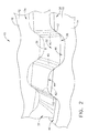
- FIG. 1 is a perspective view of an exemplary coupling 10.
- Figure 2 is a perspective view of a portion of coupling 10.
- Coupling 10 includes a first coupling member 12 and a second coupling member 14.
- Coupling members 12 and 14 each include a substantially cylindrically shaped body 16 and 18, respectively.
- Bodies 16 and 18 are each annular and extend between a respective first end 20 or 22 and a respective second end 24 or 26.
- a central axis 27 respectively, extends through bodies 16 and 18.
- a bore 28 and 30 extends through each respective body 16 and 18 between each respective first end 20 or 22 and each respective second end 24 and 26. More specifically, bores 28 and 30 are substantially concentric with respect to bodies 16 and 18, respectively.
- a plurality of teeth 32 extend outwardly from each respective body second end 28 and 30. More specifically, each tooth 32 extends outwardly from a respective root 36 to a respective tip 38. More specifically, each tip 38 is truncated and forms a mating surfaces 40. A plurality of respective troughs 44 and 46 are defined between adjacent teeth 32.
- members 12 and 14 are rotatably coupled together. More specifically, when coupled together, members 12 and 14 are aligned such that teeth 32 extending from body 16 are aligned with, and received within troughs 46, and such that teeth 32 extending from body 18 are aligned with, and received within troughs 44 such that rotational movement of body 16 or 18 with respect to the other body 18 or 16, respectively, is prevented.
- FIG 3 is a perspective view of an exemplary machining assembly 100 for machining a coupling, such as coupling 10 (shown in Figures 1 and 2).
- Assembly 100 includes a machine base 102, a machine tool 104, and a pallet assembly 106.
- Machine tool 104 is coupled to base 102 and includes a tool storage carousel 108 moveably coupled thereto in any suitable manner.
- machine tool 104 is a computer numeric control (CNC) machining center.
- Carousel 108 includes a plurality of grinding wheels 110 that are removably coupled thereto in any suitable manner, and may also include any number of other machining tools 112 and/or inspection tools 114 that are also removably coupled thereto in any suitable manner.
- Machine tool 104 also includes an automatic tool changer 116 coupled thereto in any suitable manner, a scrubber assembly 118 movably coupled thereto in any suitable manner, and a chuck 120.
- Chuck 120 includes a tool, and more specifically in the exemplary embodiment, grinding wheel 110, coupled thereto.
- Tool changer 116 removes a tool from chuck 116 and replaces the removed tool with another tool selected from carousel 108.
- Chuck 120 is configured to rotate about an axis of rotation 122.
- Scrubber assembly 118 is also rotatable about axis of rotation 122 and provides coolant to a tool.
- Pallet assembly 106 includes a pallet base 124, an automatic pallet changer 126, and a plurality of pallets 128.
- Pallets 128 are each removably coupled to base 102 and each includes a fixture base 130 and a fixture tower 132 that extends outwardly from fixture base 130.
- Each fixture tower 130 includes a plurality of quick-change fixtures 134 coupled thereto in any suitable manner.
- Fixtures 134 are each removably coupled to at least one of coupling members 12 and 14, and a dressing roll (not shown in Figure 3). Accordingly, each fixture tower 130 can include a plurality of fixtures 134, wherein each fixture is configured to couple with a different configuration of a coupling member 12 and 14, or a dressing roll.
- Each pallet 128 is removably coupled to pallet base 124.
- Pallet changer 126 couples and uncouples each pallet 128 to pallet base 124.
- Pallet base 124 is positionable along axis 122, and each pallet 128 is rotatable with respect to pallet base 124 along an axis of rotation 136 when a pallet 128 is coupled to pallet base 124.
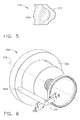
- FIG 4 is a perspective partial cut-away view of a portion of an exemplary grinding wheel 110 for use with machining assembly 100 (shown in Figure 3).
- Figure 5 is a cross-sectional view of a portion of grinding wheel 110 and taken along line 5-5.
- grinding wheel 110 is fabricated from aluminum oxide.
- wheel 110 is fabricated from cubic boron nitride (CBN).
- Grinding wheel 110 includes an arbor portion 200, a grinding wheel body 202, and a working projection 204. Arbor portion 200 is removably coupled to machine tool chuck 120 (shown in Figure 3) in any suitable manner.
- Grinding wheel working projection 204 extends outwardly from body 202 along an axis of rotation 206 and between a base 208 and a tip 210.
- Projection 204 is substantially annular and includes an abrasive working surface 212 adjacent tip 210.
- Surface 212 is configured to machine teeth troughs 44 and 46, such that teeth 32 are defined between adjacent troughs 44 or 46.
- surface 212 is a vitrified abrasive surface.
- a coolant passage 214 extends completely through arbor portion 200 and body 202 to a coolant chamber 216 defined within body 202 between a coolant plate 218 and a downstream end 220 of passage 214.
- coolant passage 214 is substantially cylindrical and is concentrically aligned with respect to axis 206 and projection 204.
- Coolant passage 214 is coupled in flow communication with a source of coolant (not shown), and delivers cooling fluid to chamber 216.
- Coolant plate 218 is coupled to a radially inner surface 222 of projection 204 and a radially inner surface 224 of body 202.
- Coolant plate 218 includes a plurality of openings 226 for channeling coolant to projection 204, and more specifically towards abrasive surface 212.
- Coolant openings 226 each include a central axis 228 that extends obliquely towards surface 212 with respect to axis of rotation 206. More specifically, during operation, coolant 230 is channeled from the coolant source through passage 214 to chamber 216. Within chamber 216, coolant 230 is channeled across an upstream surface 232 of plate 218 and through openings 226, wherein the cooling fluid is then channeled towards abrasive surface 212.
- grinding wheel projection 204 is herein described and illustrated in the exemplary manner, it should be understood that the particular geometry and cross-sectional shape of projection 204, and more specifically abrasive surface 212, will vary depending on the particular configuration and geometrical shape of coupling 10. The embodiment illustrated is intended as exemplary, and is not intended to limit the geometry and cross-sectional shape of projection 204 including abrasive surface 212.
- FIG 6 is a perspective view of an exemplary scrubber assembly 300 for use with grinding wheel 110 (shown in Figure 4), and in an operational position.
- Figure 7 is a perspective view of scrubber assembly 300 scrubber assembly 300 in a retracted position.
- Figure 8 is a cross-sectional view of a portion of scrubber assembly 300 taken along line 8-8.
- Assembly 300 supplies cleaning fluid, and includes a base 302 that is coupled to machine tool 104 (shown in Figure 3) in any suitable manner.
- Base 302 is rotatable with respect to machine tool 104, with respect to machine tool chuck 120 (shown in Figure 3), and about axis 122 (shown in Figure 3).
- Base 302 includes a first fluid duct 304 extending outwardly therefrom generally along axis 122 and having a fluid passageway 306 defined therein.
- First duct 304 extends outwardly along axis 122 to a downstream end 308 of duct 304.
- Passageway 306 is coupled in flow communication with a source of fluid (not shown).
- a second fluid duct 310 extends outwardly from first duct 304 and is substantially perpendicular to duct 304 and axis 122.
- duct 304 is formed integrally with duct 310.
- duct 304 is an independent component fixedly coupled to duct 310.
- Second duct 310 includes a passageway 312 that is defined therein, and is in flow communication with passageway 306. Second duct 310 also includes a plurality of nozzles 314 that extend outwardly from duct 310 along axis 122 and towards chuck 120 and wheel 110.
- Assembly 300 includes an operational position 316 (shown in Figure 6), wherein during operation of machine tool 104, and more specifically grinding wheel 110, assembly 300 rotates around grinding wheel 110 such that nozzles 314 direct a coolant 318 delivered from passageways 306 and 312 to wheel 110, and more specifically abrasive surface 212 (shown in Figure 4).
- Assembly 300 also includes a retracted position 320 (shown in Figure 7), wherein assembly 300 does not deliver fluid for cleaning to wheel 110. More specifically, retracted position 320 may be used during a wheel 110, or tool 112 or 114, change, and also may be used when a conventional tool 112 or 114 is coupled to chuck 120.
- FIG 9 is a perspective view of an exemplary dressing roll 400 for use with pallet assembly 106 (shown in Figure 3).
- dressing roll 400 is configured to removably couple to fixtures 134 (shown in Figure 3) in any suitable manner.
- Roll 400 includes a first annular portion 402, a second annular portion 404 extending outwardly from first portion 402, a third annular portion 406 extending outwardly from second portion 404, and a fourth annular portion 408 extending outwardly from third portion 406.
- Second portion 404, third portion 406, and fourth portion 408 are each configured to dress at least one configuration of wheel 110 (shown in Figure 4).
- other dressing rolls 400 may be coupled to assembly 106 to include even more configurations of wheel 110.
- dressing roll 400 provides a continuous-path dressing system. More specifically, machine tool 104 is configured to generally simultaneously position wheel 110 and dress wheel 110 using roll 400. In one embodiment, at least one of second portion 404, third portion 406, or fourth portion 408 includes diamond plating on an outer surface thereof for dressing wheel 110.
- an operator loads at least one coupling member 12 and 14 onto fixtures 134 and a particular coupling member configuration is chosen to be machined.
- assembly 100 chooses the appropriate grinding wheel 110 from carousel 108 and couples the chosen wheel 110 to chuck 120.
- assembly 100 chooses a pallet 128 that contains an appropriate dressing roll 400 for dressing the chosen wheel 110, the dressing roll 400 is aligned with the chosen wheel 110, and machine tool 104 dresses the wheel 110 using roll 400.
- Assembly 100 then chooses a pallet 128 that contains a coupling member 12 or 14 desired to be machined, aligns the chosen coupling 12 or 14 with grinding wheel 110, and machines the chosen coupling 12 or 14 using the chosen grinding wheel 110.
- assembly 110 is coupled to at least one processor (not shown) that facilitates executing the above-described method for machining a coupling 12 or 14.
- the above-described machining assembly is cost-effective, highly reliable, and highly accurate for machining a coupling. More specifically, the assembly allows a plurality of coupling configurations to be machined without manually changing machine tools and machine fixtures, resulting in lower cycle times and possibly a reduced inventory. In addition, the above-described assembly provides improved cooling to a grinding wheel, and further provides a continuous path dressing system. Because of the above, the machining assembly facilitates machining a higher quality coupling having a decreased dimensional variation in a cost-effective and reliable manner.
Landscapes
- Engineering & Computer Science (AREA)
- Mechanical Engineering (AREA)
- Grinding-Machine Dressing And Accessory Apparatuses (AREA)
- Polishing Bodies And Polishing Tools (AREA)
- Grinding Of Cylindrical And Plane Surfaces (AREA)
- Grinding And Polishing Of Tertiary Curved Surfaces And Surfaces With Complex Shapes (AREA)
Applications Claiming Priority (2)
| Application Number | Priority Date | Filing Date | Title |
|---|---|---|---|
| US330384 | 1981-12-14 | ||
| US10/330,384 US7052379B2 (en) | 2002-12-27 | 2002-12-27 | Methods and apparatus for machining a coupling |
Publications (1)
| Publication Number | Publication Date |
|---|---|
| EP1440758A1 true EP1440758A1 (en) | 2004-07-28 |
Family
ID=32594746
Family Applications (1)
| Application Number | Title | Priority Date | Filing Date |
|---|---|---|---|
| EP03258112A Ceased EP1440758A1 (en) | 2002-12-27 | 2003-12-22 | Methods and apparatus for machining a coupling |
Country Status (3)
| Country | Link |
|---|---|
| US (2) | US7052379B2 (enExample) |
| EP (1) | EP1440758A1 (enExample) |
| JP (1) | JP2004209636A (enExample) |
Cited By (2)
| Publication number | Priority date | Publication date | Assignee | Title |
|---|---|---|---|---|
| WO2011082240A1 (en) | 2009-12-29 | 2011-07-07 | Rolls-Royce Corporation | Face coupling |
| TWI406723B (enExample) * | 2010-05-12 | 2013-09-01 |
Families Citing this family (17)
| Publication number | Priority date | Publication date | Assignee | Title |
|---|---|---|---|---|
| US7052379B2 (en) * | 2002-12-27 | 2006-05-30 | General Electric Company | Methods and apparatus for machining a coupling |
| AT502503B1 (de) * | 2003-09-04 | 2007-04-15 | Schrottner Gerhard | Ringsystem zur mediumsführung bei schleifscheiben |
| US7334331B2 (en) * | 2003-12-18 | 2008-02-26 | General Electric Company | Methods and apparatus for machining components |
| US20080051013A1 (en) * | 2006-04-05 | 2008-02-28 | Burgess Greg M | Methods and apparatus for machining a coupling |
| DE102007042667A1 (de) * | 2007-09-10 | 2009-03-12 | Schneider Gmbh & Co. Kg | Poliermaschine für Linsen und Verfahren zum Polieren einer Linse mit einer Bearbeitungsmaschine |
| DE102007054433A1 (de) * | 2007-11-13 | 2009-05-14 | Haas Schleifmaschinen Gmbh | Schleifmaschine |
| EP2230048B1 (en) * | 2009-03-19 | 2013-05-01 | Siemens Aktiengesellschaft | Method and tool for dressing a cup-shaped grinding wheel |
| EP2535516B1 (fr) * | 2011-06-17 | 2014-02-26 | Techspace Aero S.A. | Procédé de soudage par friction d'aubes à un tambour de compresseur axial et dispositif correspondant |
| TWI542443B (zh) * | 2011-07-07 | 2016-07-21 | 鴻海精密工業股份有限公司 | 拋光裝置 |
| KR101974379B1 (ko) * | 2012-05-22 | 2019-09-06 | 삼성디스플레이 주식회사 | 기판 연마 장치 및 기판 연마 방법 |
| JP6329728B2 (ja) * | 2013-03-21 | 2018-05-23 | 株式会社ディスコ | 研削装置 |
| JP6117030B2 (ja) * | 2013-07-08 | 2017-04-19 | Sumco Techxiv株式会社 | 飛散板、研削ホイール、および、研削装置 |
| ES2729606T3 (es) * | 2014-08-29 | 2019-11-05 | Perini Fabio Spa | Procedimiento y máquina para cortar bobinas de material en banda bobinado |
| US9969053B2 (en) * | 2015-05-13 | 2018-05-15 | GM Global Technology Operations LLC | Grinder adaptor assembly |
| GB201705265D0 (en) | 2017-03-31 | 2017-05-17 | Ncmt Ltd | Method and apparatus |
| CN112355811B (zh) * | 2020-11-03 | 2023-04-04 | 自贡硬质合金有限责任公司 | 一种非连贯环槽的加工方法 |
| CN118305377B (zh) * | 2024-06-11 | 2024-08-06 | 天津金昱机电工程有限公司 | 一种自定位的球磨机齿轮加工用磨削机 |
Citations (3)
| Publication number | Priority date | Publication date | Assignee | Title |
|---|---|---|---|---|
| US5139005A (en) * | 1990-08-14 | 1992-08-18 | The Gleason Works | Universal dressing roller and method and apparatus for dressing cup-shaped grinding wheels |
| US5220749A (en) * | 1991-11-07 | 1993-06-22 | The University Of Rochester | Grinding apparatus |
| EP1184122A1 (en) * | 2000-09-04 | 2002-03-06 | Honda Giken Kogyo Kabushiki Kaisha | Method of forming tooth grooves |
Family Cites Families (31)
| Publication number | Priority date | Publication date | Assignee | Title |
|---|---|---|---|---|
| US2746220A (en) * | 1953-08-28 | 1956-05-22 | Thomas Emil Leonard | Grinding wheel cooling device |
| FR2229505B1 (enExample) * | 1973-05-17 | 1976-10-15 | Toyoda Machine Works Ltd | |
| US4016395A (en) | 1974-12-12 | 1977-04-05 | Colt Industries Operating Corporation | Wire electrode feed system for electrical discharge machining |
| US4528743A (en) * | 1982-01-16 | 1985-07-16 | Hauni-Werke Korber & Co. Kg | Grinding machine with magazine for spare grinding wheels |
| US4791761A (en) * | 1982-09-30 | 1988-12-20 | John Goudie Associates, Inc. | Lockable display frame |
| US4570609A (en) * | 1984-10-05 | 1986-02-18 | Hogue John J | Water-cooled hub for flush-cut concrete saws |
| CH670792A5 (enExample) * | 1985-06-29 | 1989-07-14 | Schaudt Maschinenbau Gmbh | |
| US4953522A (en) * | 1987-11-27 | 1990-09-04 | Schaudt Maschinenbau Gmbh | Method of dressing grinding wheels in grinding machines |
| US4841126A (en) | 1987-12-28 | 1989-06-20 | Mcwilliams Machinery Sales, Division Of Bridgeport Machines Inc. | Rotary table wire EDM machine |
| JPH04176511A (ja) * | 1990-11-06 | 1992-06-24 | Citizen Watch Co Ltd | ギアカップリングの歯型研削方法および研削装置 |
| EP0512956B1 (fr) * | 1991-05-07 | 1994-09-07 | Voumard Machines Co. S.A. | Rectifieuse à commande numérique |
| JPH0761585B2 (ja) * | 1991-07-03 | 1995-07-05 | 社団法人日本工作機械工業会 | 複数の加工要素を持つ加工システム |
| US5191711A (en) | 1991-12-23 | 1993-03-09 | Allied-Signal Inc. | Compressor or turbine blade manufacture |
| US5993297A (en) * | 1994-09-06 | 1999-11-30 | Makino Inc. | Superabrasive grinding wheel with integral coolant passage |
| JPH08243846A (ja) | 1995-03-06 | 1996-09-24 | Mitsubishi Electric Corp | ワイヤ放電加工装置及び方法 |
| JP3540474B2 (ja) | 1995-11-11 | 2004-07-07 | 株式会社ソディック | ワイヤ放電加工装置の基準接触位置の位置決め方法及びその装置 |
| CN1078120C (zh) * | 1996-02-15 | 2002-01-23 | 株式会社泽塔平和 | 切削机床和磨床中冷却液的供给的方法和装置 |
| GB9615511D0 (en) * | 1996-07-24 | 1996-09-04 | Western Atlas Uk Ltd | Improvements relating to grinding methods and apparatus |
| FR2752762B1 (fr) * | 1996-08-29 | 1998-10-02 | Snecma | Meule de rectification avec arrosage incorpore |
| US5813593A (en) | 1996-11-15 | 1998-09-29 | General Electric Company | Translational friction welding apparatus and method |
| US5847350A (en) | 1997-06-16 | 1998-12-08 | General Electric Company | Adjustable mount |
| JP3730406B2 (ja) * | 1998-04-30 | 2006-01-05 | 株式会社ニデック | 眼鏡レンズ加工装置 |
| JP2000052144A (ja) * | 1998-08-11 | 2000-02-22 | Ishikawajima Harima Heavy Ind Co Ltd | カービックカップリングの製作方法及び装置 |
| JP2000237957A (ja) * | 1999-02-22 | 2000-09-05 | Hitachi Seiki Co Ltd | 研削盤 |
| CH694580A5 (de) * | 1999-04-29 | 2005-04-15 | Ip Vitro Vidrio Y Cristal Ltd | Vorrichtung zum Bearbeiten der Kante einer Glasscheibe. |
| US6158104A (en) | 1999-08-11 | 2000-12-12 | General Electric Co. | Assembly jig for use with integrally covered bucket blades |
| US6306022B1 (en) * | 2000-06-02 | 2001-10-23 | Promos Technologies, Inc. | Chemical-mechanical polishing device |
| JP3844420B2 (ja) * | 2000-09-04 | 2006-11-15 | 株式会社牧野フライス製作所 | マシニングセンタ及びその工具交換方法 |
| JP2002103139A (ja) * | 2000-09-29 | 2002-04-09 | Komatsu Ltd | 歯車研削加工方法、並びに歯車研削用タレットヘッド及び歯車研削工具 |
| US7052379B2 (en) | 2002-12-27 | 2006-05-30 | General Electric Company | Methods and apparatus for machining a coupling |
| US7011567B2 (en) * | 2004-02-05 | 2006-03-14 | Robert Gerber | Semiconductor wafer grinder |
-
2002
- 2002-12-27 US US10/330,384 patent/US7052379B2/en not_active Expired - Fee Related
-
2003
- 2003-12-22 EP EP03258112A patent/EP1440758A1/en not_active Ceased
- 2003-12-25 JP JP2003428678A patent/JP2004209636A/ja active Pending
-
2006
- 2006-04-05 US US11/397,999 patent/US7335091B2/en not_active Expired - Fee Related
Patent Citations (3)
| Publication number | Priority date | Publication date | Assignee | Title |
|---|---|---|---|---|
| US5139005A (en) * | 1990-08-14 | 1992-08-18 | The Gleason Works | Universal dressing roller and method and apparatus for dressing cup-shaped grinding wheels |
| US5220749A (en) * | 1991-11-07 | 1993-06-22 | The University Of Rochester | Grinding apparatus |
| EP1184122A1 (en) * | 2000-09-04 | 2002-03-06 | Honda Giken Kogyo Kabushiki Kaisha | Method of forming tooth grooves |
Cited By (4)
| Publication number | Priority date | Publication date | Assignee | Title |
|---|---|---|---|---|
| WO2011082240A1 (en) | 2009-12-29 | 2011-07-07 | Rolls-Royce Corporation | Face coupling |
| CN102893044A (zh) * | 2009-12-29 | 2013-01-23 | 劳斯莱斯公司 | 面联接器 |
| EP2519755A4 (en) * | 2009-12-29 | 2014-02-26 | Rolls Royce Corp | FRONT SURFACE CLUTCH |
| TWI406723B (enExample) * | 2010-05-12 | 2013-09-01 |
Also Published As
| Publication number | Publication date |
|---|---|
| US7335091B2 (en) | 2008-02-26 |
| US20070049182A1 (en) | 2007-03-01 |
| JP2004209636A (ja) | 2004-07-29 |
| US20040132390A1 (en) | 2004-07-08 |
| US7052379B2 (en) | 2006-05-30 |
Similar Documents
| Publication | Publication Date | Title |
|---|---|---|
| US20080051013A1 (en) | Methods and apparatus for machining a coupling | |
| US7335091B2 (en) | Methods and apparatus for machining a coupling | |
| US7393261B2 (en) | Cylindrical grinding method for producing hard metal tools and cylindrical grinding machine for grinding cylindrical starting bodies during the production of hard metal tools | |
| EP1184122B1 (en) | Method of forming tooth grooves | |
| JP6012705B2 (ja) | 工作物への歯部の作製方法 | |
| US20100062690A1 (en) | Method of grinding an indexable insert and grinding wheel for carrying out the grinding method | |
| CN113385900B (zh) | 测量-铣削-去毛刺-磨抛一体化的机匣加工装置及方法 | |
| JPH0899242A (ja) | 複合加工用の工作機械 | |
| US6309291B1 (en) | Brush cutter | |
| CN113199257A (zh) | 一种铣抛一体化装备及加工方法 | |
| CN107088753A (zh) | 一种涡轮盘类零件榫槽边缘光整加工工艺及加工装置 | |
| US20120230791A1 (en) | Method and apparatus for manufacturing bevel gears | |
| JP7741573B2 (ja) | 物体に対する複数の製造作業を実施するための方法および装置 | |
| CN110253231B (zh) | 一种去除实体保持架毛刺的加工方法 | |
| JPH0747266B2 (ja) | 目直し工具を備えた研削機の心押し台 | |
| CN216126647U (zh) | 一种适用于内腔弧形轨道的加工刀具组件 | |
| JPH04240061A (ja) | 小径穴の内面加工方法およびその装置 | |
| JP4682436B2 (ja) | 微細凹凸加工方法および微細凹凸加工装置 | |
| CN119681792A (zh) | 一种双端面磨削设备用分体式夹具 | |
| JP2004090175A (ja) | バニシング装置、バニシング装置を搭載した自動旋盤及び自動旋盤によるバニシング方法 | |
| JP2003071605A (ja) | 2主軸対向旋盤を用いた複数ワークの連続加工方法 | |
| JPH1128704A (ja) | 刃先にランドを有するフライス | |
| JP2004188582A (ja) | 研削工具およびそれを用いた研削加工方法 | |
| JPH07328824A (ja) | 中ぐり加工方法、および、中ぐり加工装置 |
Legal Events
| Date | Code | Title | Description |
|---|---|---|---|
| PUAI | Public reference made under article 153(3) epc to a published international application that has entered the european phase |
Free format text: ORIGINAL CODE: 0009012 |
|
| AK | Designated contracting states |
Kind code of ref document: A1 Designated state(s): AT BE BG CH CY CZ DE DK EE ES FI FR GB GR HU IE IT LI LU MC NL PT RO SE SI SK TR |
|
| AX | Request for extension of the european patent |
Extension state: AL LT LV MK |
|
| 17P | Request for examination filed |
Effective date: 20050128 |
|
| AKX | Designation fees paid |
Designated state(s): DE FR GB IT |
|
| 17Q | First examination report despatched |
Effective date: 20050315 |
|
| STAA | Information on the status of an ep patent application or granted ep patent |
Free format text: STATUS: THE APPLICATION HAS BEEN REFUSED |
|
| 18R | Application refused |
Effective date: 20070510 |