EP1437645A2 - Méthode de mesure de position/orientation, et appareil de mesure de position/orientation - Google Patents
Méthode de mesure de position/orientation, et appareil de mesure de position/orientation Download PDFInfo
- Publication number
- EP1437645A2 EP1437645A2 EP20030258246 EP03258246A EP1437645A2 EP 1437645 A2 EP1437645 A2 EP 1437645A2 EP 20030258246 EP20030258246 EP 20030258246 EP 03258246 A EP03258246 A EP 03258246A EP 1437645 A2 EP1437645 A2 EP 1437645A2
- Authority
- EP
- European Patent Office
- Prior art keywords
- image
- orientation
- indicator
- coordinate
- image sensing
- Prior art date
- Legal status (The legal status is an assumption and is not a legal conclusion. Google has not performed a legal analysis and makes no representation as to the accuracy of the status listed.)
- Granted
Links
Images


Classifications
-
- G—PHYSICS
- G06—COMPUTING; CALCULATING OR COUNTING
- G06F—ELECTRIC DIGITAL DATA PROCESSING
- G06F3/00—Input arrangements for transferring data to be processed into a form capable of being handled by the computer; Output arrangements for transferring data from processing unit to output unit, e.g. interface arrangements
- G06F3/01—Input arrangements or combined input and output arrangements for interaction between user and computer
- G06F3/03—Arrangements for converting the position or the displacement of a member into a coded form
- G06F3/0304—Detection arrangements using opto-electronic means
- G06F3/0325—Detection arrangements using opto-electronic means using a plurality of light emitters or reflectors or a plurality of detectors forming a reference frame from which to derive the orientation of the object, e.g. by triangulation or on the basis of reference deformation in the picked up image
-
- G—PHYSICS
- G01—MEASURING; TESTING
- G01B—MEASURING LENGTH, THICKNESS OR SIMILAR LINEAR DIMENSIONS; MEASURING ANGLES; MEASURING AREAS; MEASURING IRREGULARITIES OF SURFACES OR CONTOURS
- G01B11/00—Measuring arrangements characterised by the use of optical techniques
- G01B11/002—Measuring arrangements characterised by the use of optical techniques for measuring two or more coordinates
Definitions
- the present invention relates to a technique for measuring the position and orientation of an image sensing device or an object that mounts the image sensing device.
- An image display apparatus that presents mixed reality is implemented by a video see-through system which superimposes and renders an image of a virtual space (e.g., virtual objects, text information, and the like rendered by computer graphics) generated in correspondence with the position and orientation of an image sensing device such as a video camera or the like on a real space image captured by the image sensing device, and displays these images.
- a virtual space e.g., virtual objects, text information, and the like rendered by computer graphics
- the image display apparatus is implemented by an optical see-through system which displays a virtual space image generated in correspondence with the position and orientation of a viewpoint of an observer on an optical see-through display mounted on the observer's head.
- a problem of alignment in mixed reality amounts to obtaining the position and orientation of an image sensing device in a scene (i.e., on a world coordinate system) in case of the video see-through system. Likewise, such problem amounts to obtaining the position and orientation of the viewpoint of the observer or display in a scene in case of the optical see-through system.
- FIG. 1 is a diagram showing the arrangement of the conventional position/orientation measurement apparatus.
- a conventional position/orientation measurement apparatus 100 comprises a subjective viewpoint indicator detection unit 110 and position/orientation calculation unit 120, and is connected to an image sensing device 130.
- a plurality of subjective viewpoint indicators Q k 1,..., K 1 ) whose positions on a world coordinate system (a coordinate system specified by defining one point on the real space as an origin, and defining three orthogonal axes as the X-, Y-, and Z-axes) are known are laid out as indicators (to be referred to as subjective viewpoint indicators) to be captured by the image sensing device 130.
- the subjective viewpoint indicators Q k are preferably set so that at least three indicators are always observed on an image captured by the image sensing device 130 when the image sensing device 130 is located at respective points within the measurement range in which the position and orientation are to be measured.
- four subjective viewpoint indicators Q 1 , Q 2 , Q 3 , and Q 4 are laid out, and three indicators Q 1 , Q 3 , and Q 4 of them are included in the field of view of the image sensing device 130.
- the subjective viewpoint indicators Q k may comprise circular markers having different colors, or feature points such as natural features or the like having different texture features.
- the indicators to be used are not particularly limited as long as the image coordinates of projected images on a captured image can be detected, and the indicators can be identified from each other.
- An image (to be referred to as a subjective viewpoint image hereinafter) output from the image sensing device 130 is input to the position/orientation measurement apparatus 100.
- the subjective viewpoint indicator detection unit 110 receives the subjective viewpoint image from the image sensing device 130, and detects the image coordinates of the subjective viewpoint indicators Q k that appear in the input image.
- the subjective viewpoint indicators Q k comprise markers having different colors
- regions corresponding to respective marker colors are detected from the subjective viewpoint image, and their barycentric positions are detected as the detected coordinates of the indicators.
- the subjective viewpoint indicators Q k comprise feature points having different texture features
- template matching using template images of the respective indicators, which are held as known information is applied to the subjective viewpoint image, thereby detecting the positions of indicators.
- the subjective viewpoint indicator detection unit 110 outputs an image coordinate u Qkn and identifier k n of each detected subjective viewpoint indicator Q kn to the position/orientation calculation unit 120.
- the position/orientation calculation unit 120 calculates the position and orientation of the image sensing device 130 on the basis of the relationship between the image coordinates u Qkn of the detected subjective viewpoint indicators Q kn and world coordinates x W Qkn of the indicators held in advance as known information.
- the position/orientation calculation unit 120 internally expresses the position and orientation to be calculated of the image sensing device 130 as three-valued vectors [x y z] T and [ ⁇ ⁇ ⁇ ] T .
- Various methods of expressing the orientation by three values are available.
- the orientation is expressed by a three-valued vector that expresses the rotation angle by its size, and the rotation axis direction by its direction.
- step S2000 the position/orientation calculation unit 120 sets an appropriate initial value (estimated values of the position and orientation) in the state vector s. For example, s derived in the process of the previous frame (time t k-1 ) may be used as the initial value, or a value predicted based on a change in derived value from old "s"s may be set.
- step S2010 the position/orientation calculation unit 120 receives the actually measured values u Qkn of the image coordinates and identifiers k n of the respective subjective viewpoint indicators Q kn detected by the subjective viewpoint indicator detection unit 110.
- step S2020 the position/orientation calculation unit 120 calculates estimated values u Qkn* of the image coordinates of the respective subjective viewpoint indicators Q kn .
- the calculation of u Qkn* is made based on a function of the world coordinates x W Qkn of indicators Q kn held as known information and the current state vector s:
- the function F C () comprises: used to calculate a coordinate x c Qkn on a camera coordinate system (a coordinate system specified by defining one point on the camera as an origin and defining three orthogonal axes as X-, Y-, and Z-axes) of the indicator of interest from x W Qkn and s; and used to calculate the image coordinate u Qkn* from the camera coordinate x C Qkn .
- f C x and f C y are the focal lengths of the image sensing device 130 in the x- and y-axis directions, and are held as known values.
- step S2060 the position/orientation calculation unit 120 corrects the state vector s using the correction value ⁇ s calculated in step S2050 by: S + ⁇ S ⁇ S and sets the corrected value as a new estimated value of s.
- the position/orientation calculation unit 120 determines in step S2070 whether or not the calculation converges using some determination criteria, i.e., whether or not error vector U is smaller than a predetermined threshold value, whether or not the correction value ⁇ s is smaller than a predetermined threshold value, and so forth. If the calculation does not converge, the unit 120 repeats the process in step S2020 and subsequent steps using the corrected state vector s.
- step S2080 the position/orientation calculation unit 120 outputs the obtained state vector s as the information of the position and orientation of the image sensing device 130.
- the information of the position and orientation is output in the form of, e.g., a viewing conversion matrix calculated from s.
- the position and orientation of the image sensing device 130 are acquired by the aforementioned method.
- the position and orientation of an object to be measured can also be calculated by setting a plurality of indicators on the object to be measured, capturing the object by an externally set objective viewpoint camera, and detecting image coordinates of projected images of the indicators in the captured objective viewpoint image (e.g., see D. G. Lowe: Fitting parameterized three-dimensional models to images, IEEE Transactions on PAMI, vol. 13, no. 5, pp. 441 - 450, 1991., and Japanese Patent Laid-Open No. 09-323280).
- the present invention has been made in consideration of the above problems, and has as a concern measure both the position and orientation of an object with high precision
- a position/orientation measurement method has the following arrangement.
- a position/orientation measurement method for calculating a position and orientation of an object comprising:
- Another aspect of the present invention provides a position/orientation measurement method which has the following arrangement.
- a position/orientation measurement method of calculating a first position/orientation parameter of an object which is attached to a first image sensing unit used to capture an image of a real space, and has a known position/orientation relationship with the first image sensing unit comprising:
- a position/orientation measurement method has the following arrangement.
- a position/orientation measurement method of calculating a position and orientation of an image sensing device as an object to be measured, which captures an image of a scene comprising:
- a position/orientation measurement apparatus has the following arrangement.
- a position/orientation measurement apparatus for calculating a position and orientation of an object, comprising:
- a position/orientation measurement apparatus measures the position and orientation of an image sensing device.
- the position/orientation measurement apparatus and position/orientation measurement method according to this embodiment measures will be described hereinafter.
- Fig. 3 is a schematic diagram showing the arrangement of a position/orientation measurement apparatus according to this embodiment. Note that the same reference numerals and symbols in Fig. 3 denote the same parts as those in Fig. 1, and a description thereof will be omitted.
- a position/orientation measurement apparatus 300 according to this embodiment comprises a subjective viewpoint indicator detection unit 110, objective viewpoint indicator detection unit 310, position/orientation calculation unit 320, and objective viewpoint camera 330, and is connected to an image sensing device 130 to be measured.
- the objective viewpoint camera 330 is fixed at a position where it can capture an image of the image sensing device 130 when the image sensing device 130 is located within the measurement range. Assume that the position and orientation of the objective viewpoint camera 330 on the world coordinate system are held in advance in the objective viewpoint indicator detection unit 310 as known values.
- a plurality of subjective viewpoint indicators Q k whose positions on the world coordinate system are known are set as indicators to be captured by the image sensing device 130 as in the prior art.
- These indicators are preferably set so that the total number of subjective viewpoint indicators observed on an image captured by the image sensing device, and objective viewpoint indicators observed on an image captured by the objective viewpoint camera 330 is at least three when the image sensing device 130 is located at respective points within the measurement range in which the position and orientation are to be measured.
- three subjective viewpoint indicators Q1, Q2, and Q3, and two objective viewpoint indicators P1 and P2 are set, two subjective viewpoint indicators Q1 and Q3 of them are included in the field of view of the image sensing device 130, and the two objective viewpoint indicators P1 and P2 are included in the field of view of the objective viewpoint camera 330.
- the objective viewpoint indicators P k are not particularly limited as long as the image coordinates of projected images on a captured image can be detected, and the indicators can be identified from each other, as in the subjective viewpoint indicators Q k . Also, both the subjective and objective viewpoint indicators may be deliberately set or may use, e.g., natural shapes, which are not deliberately set, as described above.
- the subjective viewpoint indicator detection unit 110 receives a subjective viewpoint image captured by the image sensing device 130, detects the image coordinates of the subjective viewpoint indicators Q k that appear in the input image, and outputs image coordinates u Qkn and identifiers k n of the detected subjective viewpoint indicators Q kn to the position/orientation calculation unit 320, as in the prior art.
- N 2
- corresponding image coordinates u Qk1 and u Qk2 are output.
- the objective viewpoint indicator detection unit 310 receives an image (to be referred to as an objective viewpoint image) captured by the objective viewpoint camera 330, detects the image coordinates of the objective viewpoint indicators P k that appear in the image by the same process as the subjective viewpoint indicator detection unit 110, and outputs image coordinates u Pkm and identifiers k m of the detected objective viewpoint indicators P km to the position/orientation calculation unit 320.
- the position/orientation calculation unit 320 calculates the position and orientation of the image sensing device 130 on the basis of the relationship between the image coordinates u Qkn of the detected subjective viewpoint indicators Q kn and world coordinates x W Qkn of the indicators held in advance as known information, and the relationship between the image coordinates u Pkm of the detected objective viewpoint indicators Q Pm and positions x C Pkm of the indicators on the objective viewpoint camera coordinate system held in advance as known information. In this way, the position and orientation of the image sensing device 130 can be measured.
- the objective viewpoint indicator detection unit 310, position/orientation calculation unit 320, and subjective viewpoint indicator detection unit 110 shown in Fig. 3 may be handled as independent devices, or their functions may be implemented by installing them as software programs in one or a plurality of computers and executing these programs by a CPU of each computer.
- the respective units are handled as software programs which can run on a single computer.
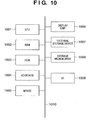
- Fig. 10 is a block diagram showing the basic arrangement of a computer which executes the objective viewpoint indicator detection unit 310, position/orientation calculation unit 320, and subjective viewpoint indicator detection unit 110 as software programs.
- Reference numeral 1001 denotes a CPU, which controls the overall computer using programs and data stored in a RAM 1002 and ROM 1003, and controls execution of the software programs of the objective viewpoint indicator detection unit-310, position/orientation calculation unit 320, and subjective viewpoint indicator detection unit 110 to implement the functions of these units.
- the RAM 1002 comprises an area for temporarily storing programs and data loaded from an external storage device 1007 and storage medium drive 1008, and a work area required for the CPU 1001 to execute various processes.
- the ROM 1003 normally stores a boot program, setup data, and the like of the computer.
- Reference numerals 1004 and 1005 respectively denote a keyboard and mouse. The operator can input various instructions to the CPU 1001 using these keyboard and mouse.
- Reference numeral 1006 denotes a display unit, which comprises a CRT, liquid crystal display, and the like, and can display, e.g., messages and the like to be displayed for position/orientation measurement of the image sensing device 130.
- the external storage device 1007 serves as a large-capacity information storage device such as a hard disk or the like, and saves an OS (operating system), software programs which respectively serve as the objective viewpoint indicator detection unit 310, position/orientation calculation unit 320, and subjective viewpoint indicator detection unit 110, and the like. Also, the device 1007 stores information described as known information in the description of this embodiment.
- OS operating system
- software programs which respectively serve as the objective viewpoint indicator detection unit 310, position/orientation calculation unit 320, and subjective viewpoint indicator detection unit 110, and the like.
- the device 1007 stores information described as known information in the description of this embodiment.
- the storage medium drive 1008 reads out programs and data stored in a storage medium such as a CD-ROM, DVD-ROM, or the like in accordance with an instruction from the CPU 1001, and outputs them to the RAM 1002 and external storage device 1007.
- Reference numeral 1009 denotes an I/F, which connects the image sensing device 130 and objective viewpoint camera 330. Images captured by these devices are fetched onto the RAM 1002 via the I/F 1009.
- Reference numeral 1010 denotes a bus which interconnects the above units.
- Fig. 4 is a flow chart showing the process for calculating parameters indicating the position and orientation of the image sensing device 130, which is implemented when the CPU 1001 executes a software program of the position/orientation calculation unit 320. Assume that the software programs of the objective viewpoint indicator detection unit 310, position/orientation calculation unit 320, and subjective viewpoint indicator detection unit 110 have already been loaded onto the RAM 1002 prior to the following process.
- step S4000 the position/orientation calculation unit 320 sets an appropriate initial value (estimated values of the position and orientation) in the state vector s. For example, s derived in the process of the previous frame (time t k-1 ) may be used as the initial value, or a value predicted based on a change in derived value from old "s"s may be set.
- step S4010 the position/orientation calculation unit 320 receives the image coordinates u Qkn and identifiers k n of the respective subjective viewpoint indicators Q kn detected by the subjective viewpoint indicator detection unit 110.
- step S4020 the position/orientation calculation unit 320 receives the image coordinates u pkm and identifiers k m of the respective subjective viewpoint indicators P km detected by the subjective viewpoint indicator detection unit 110.
- the position/orientation calculation unit 320 checks in step S4030 if the total number of input indicators (i.e., N + M) is 3 or more. If the total number of indicators is less than 3, the flow jumps to step S4130 while skipping an update process of s implemented in steps S4040 to S4120.
- step S4040 the position/orientation calculation unit 320 calculates estimated values u Qkn* of the image coordinates of the respective subjective viewpoint indicators Q kn on the basis of equations (1) to (4). That is, under the assumption that the position and orientation of the image sensing device 130 follow the previously calculated state vector s, the estimated values of the image coordinates of the respective subjective viewpoint indicators are calculated in accordance with the position/orientation relationship between the image sensing device 130 and subjective viewpoint indicators.
- step S4050 the position/orientation calculation unit 320 calculates an error ⁇ u Qkn between the estimated value u Qkn* and actually measured value u Qkn of the image coordinate of each subjective viewpoint indicator Q kn on the basis of equation (5).
- step S4070 the position/orientation calculation unit 320 calculates estimated values u Pkm* of the image coordinates of the respective objective viewpoint indicators P km . That is, the position/orientation calculation unit 320 calculates the estimated values of the respective objective viewpoint indicators in accordance with the position/orientation relationship between the image sensing device 130 and objective viewpoint indicators, under the assumption that the position and orientation of the image sensing device 130 follow the previously calculated state vector s.
- u Pkm* The calculation of u Pkm* is made based on a function of the camera coordinates (coordinate values on the camera coordinate system) x C Pkm of indicators P km held as known information and the current state vector s:
- the function F B () comprises: used to calculate a coordinate x B Pkm on an objective viewpoint camera coordinate system (a coordinate system specified by defining one point on the objective viewpoint camera 330 as an origin and defining three orthogonal axes as X-, Y-, and Z-axes) of the indicator of interest from x C Pkm and s; and used to calculate the image coordinate u Pkm * from the camera coordinate x B Pkm .
- f B x and f B y are the focal lengths of the objective viewpoint camera 330 in the x- and y-axis directions, and are held as known values.
- M WB is a conversion matrix used to convert the coordinate on the objective viewpoint camera coordinate system into that on the world coordinate system, and is calculated in advance on the basis of the position and orientation of the objective viewpoint camera 330 on the world coordinate system, which are held in advance as known value.
- step S4100 the position/orientation calculation unit 320 specifies an error vector U and matrix ⁇ on the basis of the errors ⁇ u Qkn , Jacobian matrices J us QKn , errors ⁇ u Pkm , and Jacobian matrices J us Pkm calculated in the above steps, and calculates a correction value ⁇ s of the state vector s by equation (9).
- the error vector U is set as a 2(N+M)-dimensional vector: by vertically lining up the errors ⁇ u Qkn and ⁇ u Pkm .
- the matrix ⁇ is set as a 2(N+m) ⁇ 6 matrix: by vertically lining up the Jacobian matrices J us Qkn and J us Pkm .
- U is an eight-dimensional vector
- ⁇ is a 8 ⁇ 6 matrix.
- step S4110 the position/orientation calculation unit 320 corrects the state vector s, i.e., parameters indicating the position and orientation of the image sensing device 130, using the correction value ⁇ s calculated in step S4100 by equation (10), and sets the corrected value as a new estimated value of s.
- the position/orientation calculation unit 320 determines in step S4120 whether or not the calculation converges, using some determination criteria, i.e., whether or not error vector U is smaller than a predetermined threshold value, whether or not the correction value ⁇ s is smaller than a predetermined threshold value, and so forth. If the calculation does not converge, the unit 320 repeats the process in step S4040 and subsequent steps using the corrected state vector s.
- the position/orientation calculation unit 320 outputs the obtained state vector s as the parameters indicating the position and orientation of the image sensing device 130 in step S4130.
- the parameters to be output an Euler angle obtained by converting the orientation component of s may be output, or a viewing conversion matrix calculated from s may be output.
- various other position/orientation description methods may be used.
- the position and orientation of the image sensing device which can minimize not only errors between neighboring indicators on the subjective viewpoint image but also those between neighboring indicators on the objective viewpoint image, can be obtained.
- the position and orientation of the image sensing device 130 can be measured with higher precision than that obtained using either one of the subjective and objective viewpoint images, and their parameters can be calculated.
- both the position and orientation of the image sensing device can be measured with high precision.
- the total number of subjective viewpoint indicators to be set in a scene can be reduced compared to the conventional method that uses the subjective viewpoint image alone.
- a position/orientation measurement apparatus measures the positions and orientations of two cameras mounted on a stereo video see-through HMD (Head Mount Display).
- HMD Head Mount Display
- Fig. 5 is a schematic diagram showing the arrangement of the position/orientation measurement apparatus according to this embodiment. Note that the same reference numerals and symbols in Fig. 5 denote the same parts as those in Figs. 1 and 3.
- a position/orientation measurement apparatus 500 according to this embodiment comprises subjective viewpoint indicator detection units 110R and 110L, objective viewpoint indicator detection unit 310, position/orientation calculation unit 520, and objective viewpoint camera 330.
- Subjective viewpoint indicators Q k are laid out in the same manner as in the first embodiment, and the functions of the objective viewpoint camera 330 and objective viewpoint indicator detection unit 310 are the same as those in the first embodiment. Hence, a detailed description thereof will be omitted.
- An HMD 540 incorporates two cameras 550R and 550L to capture videos of the real image corresponding to the right and left viewpoints of the observer.
- a left camera coordinate system a coordinate system specified by defining one point on the camera 550L as an origin and defining three orthogonal axes as the X-, Y-, and Z-axes
- Right and left subjective viewpoint images captured by the cameras 550R and 550L are respectively input to the subjective viewpoint indicator detection units 110R and 110L.
- the subjective viewpoint indicator detection units 110R and 110L execute subjective viewpoint indicator detection processes of the right and left subjective viewpoint images input to them by the same process as that in the subjective viewpoint indicator detection unit 110 in the first embodiment, and output the image coordinates and identifiers of the detected indicators to the position/orientation calculation unit 520.
- u R QkRn and u L QkLn respectively represent the image coordinates of the indicators detected by the subjective viewpoint indicator detection units 110R and 110L.
- N R and N L respectively represent the total numbers of detected indicators.
- the position/orientation calculation unit 520 calculates the positions and orientations of the two cameras 550R and 550L on the basis of the image coordinates u QkRn and u QkLn of the detected subjective viewpoint indicators Q kn , and the image coordinates u Pkm of the objective viewpoint indicators P km .
- the objective viewpoint indicator detection unit 310, position/orientation calculation unit 520, and subjective viewpoint indicator detection units 110R and 110L shown in Fig. 5 may be handled as independent devices, or their functions may be implemented by installing them as software programs in one or a plurality of computers and executing these programs by a CPU of each computer.
- the respective units are handled as software programs which can run on a single computer.
- the basic arrangement of this computer is that shown in Fig. 10.
- an error vector U is set as a 2(N L +N R +M)-dimensional vector by vertically lining up errors ⁇ u L QkLn , ⁇ u R QkRn , and ⁇ u Pkm .
- a matrix ⁇ is set as a 2(N L +N R +M) ⁇ 6 matrix by vertically lining up Jacobian matrices J uLs QkLn , J uRs QkRn , and J us Pkm .
- U is a 12-dimensional vector
- ⁇ is a 12 ⁇ 6 matrix.
- the errors and Jacobian matrices associated with the subjective viewpoint indicators are calculated on the basis of unique parameters (focal lengths) of the cameras 550R and 550L by the same process as the calculations of the errors and Jacobian matrices associated with the subjective viewpoint indicators (steps S4040 to S4060) in the first embodiment.
- M CLCR is the conversion matrix from the right camera coordinate system to the left camera coordinate system, and is calculated in advance on the basis of the position and orientation of the camera 550R on the left camera coordinate system, which are held in advance as known values.
- the outputs of the position/orientation measurement apparatus 500 of this embodiment may be viewing conversion matrices which indicate the positions and orientations of the cameras 550R and 550L, or may be two six-dimensional vectors which indicate the positions and orientations of the cameras 550R and 550L.
- an apparatus an image generation apparatus in case of this embodiment
- which uses the outputs from the position/orientation measurement apparatus 500 holds the positional relationship (e.g., the aforementioned matrix M CLCR ) between the cameras 550R and 550L, only data indicating the position and orientation of one camera may be output.
- both the positions and orientations of the two cameras mounted on the stereo video see-through HMD can be measured with high precision.
- the first embodiment uses one objective viewpoint camera.
- the number of objective viewpoint cameras is not limited to one.
- expansion of the measurement range and improvement of measurement stability are expected.
- Fig. 6 is a schematic diagram showing the arrangement of the position/orientation measurement apparatus according to this embodiment. Note that the same reference numerals and symbols in Fig. 6 denote the same parts as those in Figs. 1 and 3.
- a position/orientation measurement apparatus 600 according to this embodiment comprises objective viewpoint cameras 330a to 330d, objective viewpoint indicator detection units 310a to 310d, a subjective viewpoint indicator detection unit 110, and a position/orientation calculation unit 620.
- subjective and objective viewpoint indicators Q and P are laid out in the same manner as in the first embodiment, and a subjective viewpoint video captured by an image sensing device 130 is input to the subjective viewpoint indicator detection unit 110. Since the function of the subjective viewpoint indicator detection unit 110 is the same as that in the first embodiment, a description thereof will be omitted.
- the objective viewpoint cameras 330a to 330d are fixed at positions where they can capture images of the image sensing device 130 when the image sensing device 130 is located within the measurement range.
- the layout of the objective viewpoint cameras 330a to 330d may be set so that the respective cameras capture regions which overlap each other to allow the objective viewpoint indicators P to be observed by a plurality of objective viewpoint cameras for the purpose of improvement of stability against occlusion, or may be set so that the respective cameras capture different regions for the purpose of expansion of the measurement range. Assume that the positions and orientations of the objective viewpoint cameras 330a to 330d on the world coordinate system are held in advance as known values.
- the objective viewpoint indicator detection units 310a to 310d receive objective viewpoint images captured by the objective viewpoint cameras 330a to 330d, execute objective viewpoint indicator detection processes, and output the image coordinates and identifiers of the detected indicators to the position/orientation calculation unit 620 by the same process as that of the objective viewpoint indicator detection unit 310 in the first embodiment.
- u a Pkan , u b Pkbn , u c Pkcn , and u d Pkdn respectively represent image coordinates of indicators detected by the objective viewpoint indicator detection units 310a to 310d.
- M a , M b , M c , and M d respectively indicate the total numbers of detected indicators.
- the position/orientation calculation unit 620 calculates the position and orientation of the image sensing device 130 on the basis of the relationship between the image coordinates and world coordinates of the detected subjective viewpoint indicators, and the relationship between the image coordinates of the objective viewpoint indicators detected by the objective viewpoint indicator detection units 310a to 310d and their positions on the objective viewpoint camera coordinate system.
- the objective viewpoint indicator detection units 310a to 310d, subjective viewpoint indicator detection unit 110, and position/orientation calculation unit 620 shown in Fig. 6 may be handled as independent devices, or their functions may be implemented by installing them as software programs in one or a plurality of computers and executing these programs by a CPU of each computer.
- the respective units are handled as software programs which can run on a single computer.
- the basic arrangement of this computer is that shown in Fig. 10.
- the process is different from the first embodiment in the following points.
- an error vector U is set as a 2(N+M a +M b +M c +M d )-dimensional vector by vertically lining up errors ⁇ u Qkn , ⁇ u a Pkam , ⁇ u b Pkbm , ⁇ u c Pkcm , and ⁇ u d Pkdm .
- a matrix ⁇ is set as a 2(N+M a +M b +M c +M d ) ⁇ 6 matrix by vertically lining up Jacobian matrices J us Qkn , J uas Pkam , J ubs Pkbm , J ucs Pkcm , and J uds Pkdm .
- the errors and Jacobian matrices associated with the subjective viewpoint indicators are calculated on the basis of unique parameters (positions on the world coordinate system and focal lengths) of the objective viewpoint cameras 330a to 330d by the same process as the calculations of the errors and Jacobian matrices associated with the subjective viewpoint indicators (steps S4040 to S4060) in the first embodiment.
- the plurality of objective viewpoint cameras are used, even when the image sensing devices moves over a broad range or the image sensing device is occluded with respect to the field of view of an arbitrary objective viewpoint camera, data that suffice to calculate the position and orientation of the image sensing device can be acquired, thus achieving expansion of the movable range and improvement of stability against occlusion or the like.
- the position/orientation measurement apparatus of this embodiment uses the four objective viewpoint cameras.
- the number of objective viewpoint cameras is not limited to four, and an arbitrary number of objective viewpoint cameras may be used.
- the first to third embodiments aim at measuring the position and orientation of the image sensing device itself, which moves three-dimensionally.
- a position/orientation measurement apparatus aims at measuring the position and orientation of an arbitrary object, and has an arrangement obtained by adding a camera that captures a subjective viewpoint image to the position/orientation measurement apparatus of the first embodiment.
- the position/orientation measurement apparatus and position/orientation measurement method will be described hereinafter.
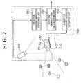
- Fig. 7 shows the arrangement of the position/orientation measurement apparatus according to this embodiment. Note that the same reference numerals and symbols in Fig. 7 denote the same parts as those in Figs. 1 and 3, and a description thereof will be omitted.
- a position/orientation measurement apparatus 700 according to this embodiment comprises a subjective viewpoint indicator detection unit 110, objective viewpoint indicator detection unit 310, position/orientation calculation unit 720, objective viewpoint camera 330, and subjective viewpoint camera 730.
- the subjective viewpoint camera 730 is fixed to an object 710 to be measured. Assume that the position and orientation of the object 710 to be measured on a subjective viewpoint camera coordinate system (a coordinate system specified by defining one point on the subjective viewpoint camera 730 as an origin, and defining three orthogonal axes as X-, Y-, and Z-axes) are known.
- a subjective viewpoint camera coordinate system a coordinate system specified by defining one point on the subjective viewpoint camera 730 as an origin, and defining three orthogonal axes as X-, Y-, and Z-axes
- These indicators are preferably set so that the total number of subjective viewpoint indicators observed on an image captured by the subjective viewpoint camera 730, and objective viewpoint indicators observed on an image captured by the objective viewpoint camera 330 is always at least three when the object 710 to be measured is located at respective points within the measurement range in which the position and orientation are to be measured.
- the functions of the objective viewpoint camera 330, subjective viewpoint indicator detection unit 110, and objective viewpoint indicator detection unit 310 are the same as those in the first embodiment, a detailed description thereof will be omitted. However, unlike in the first embodiment, an image captured by the subjective viewpoint camera 730 is input to the subjective viewpoint indicator detection unit 110 as a subjective viewpoint image.
- the position/orientation calculation unit 720 calculates the position and orientation of the subjective viewpoint camera 730 on the world coordinate system as an unknown vector s by the same process as that of the position/orientation calculation unit 320 in the first embodiment shown in Fig. 4.
- the position/orientation calculation unit 720 calculates the position and orientation of the object 710 to be measured on the world coordinate system as the product of coordinate conversion matrices on the basis of the calculated position and orientation of the subjective viewpoint camera 730 on the world coordinate system, and the position and orientation of the object 710 to be measured on the subjective viewpoint camera coordinate system as known values. Then, the unit 720 outputs the calculated position and orientation of the object 710.
- the subjective viewpoint indicator detection unit 110, objective viewpoint indicator detection unit 310, and position/orientation calculation unit 720 shown in Fig. 7 may be handled as independent devices, or their functions may be implemented by installing them as software programs in one or a plurality of computers and executing these programs by a CPU of each computer.
- the respective units are handled as software programs which can run on a single computer.
- the basic arrangement of this computer is that shown in Fig. 10.
- the position/orientation calculation unit 720 of this embodiment calculates the position and orientation of the subjective viewpoint camera 730 as the state vector s.
- the unit 720 may directly calculate the position and orientation of the object 710 to be measured as the state vector s.
- M co is a conversion matrix from a measurement object coordinate system (a coordinate system specified by defining one point on the object 710 to be measured as an origin, and defining three orthogonal axes as the X-, Y-, and Z-axes) to
- each of the position/orientation calculation units 320, 520, 620, and 720 calculates s that minimizes the sum total of errors between the detected coordinates of the subjective and objective viewpoint indicators and the calculated values of these indicators to have the 6-valued state vector s indicating the position and orientation as an unknown value.
- the method of acquiring the position and orientation of an object to be measured by using geometric constraint conditions obtained from both the subjective and objective viewpoint images together is not limited to such specific method.
- a position/orientation measurement apparatus of this embodiment is characterized by having, as its building component, a position/orientation calculation unit that adopts a method different from the method of minimizing the total error.
- the arrangement of the position/orientation measurement apparatus of this embodiment is basically the same as that of the first embodiment, except that the position/orientation calculation unit 320 is replaced by a position/orientation calculation unit 320' different from that of the first embodiment.
- the position/orientation measurement apparatus and position/orientation measurement method according to this embodiment will be described hereinafter.
- the respective units are handled as software programs which can run on a single computer.
- the basic arrangement of this computer is that shown in Fig. 10. Also, in a description of this embodiment, all pieces of known information are saved in the external storage device 1007.
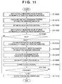
- Fig. 11 is a flow chart showing the process for calculating parameters indicating the position and orientation of the image sensing device 130, which is implemented when the CPU 1001 executes a software program of the position/orientation calculation unit 320'. Assume that the software programs of the objective viewpoint indicator detection unit 310, position/orientation calculation unit 320', and subjective viewpoint indicator detection unit 110 have already been loaded onto the RAM 1002 prior to the following process.
- step S11000 the position/orientation calculation unit 320' receives image coordinates u Pa and u Pb of objective viewpoint indicators P detected by the objective viewpoint indicator detection unit 310.
- the position/orientation calculation unit 320' receives image coordinates u Pa and u Pb of objective viewpoint indicators P detected by the objective viewpoint indicator detection unit 310.
- only one objective viewpoint indicator is used in the subsequent process.
- the position/orientation calculation unit 320' selects an appropriate one point as an image coordinate u P of the objective viewpoint indicator P.
- the position/orientation calculation unit 320' calculates parameters which express one line that constrains the position of the objective viewpoint indicator P on the world coordinate system, on the basis of the image coordinate u P . That is, the unit 320' calculates slop components (direction vector) hx, hy, and hz of the line on the world coordinate system on the basis of the image coordinate u P by: where f B x and f B y are the focal lengths of the objective viewpoint camera 330 in the x- and y-axis directions, and are held in advance in the external storage device 1007 as known values. The unit 320' sets the calculated components hx, hy, and hz as parameters of the line.
- a point on the line on the world coordinate system can be expressed as a function of a parameter ⁇ by: where x WB , y WB , and z WB define the position of the objective viewpoint camera 330 on the world coordinate system, and are held in advance as known values in the external storage device 1007.
- the line given by equation (22) passes the position of the objective viewpoint camera 330 on the world coordinate system, and that of the objective viewpoint indicator P on the world coordinate system, and the position of the objective viewpoint indicator P on the world coordinate system is obtained when the parameter T assumes an appropriate value.
- step S11020 the position/orientation calculation unit 320' sets an appropriate initial value in the state vector s.
- s derived in the process of the previous frame time t k-1
- a value predicted based on a change in derived value from old "s"s may be set.
- step S11030 the position/orientation calculation unit 320' receives the image coordinates u Qkn and identifiers k n of the respective subjective viewpoint indicators Q kn detected by the subjective viewpoint indicator detection unit 110.
- the position/orientation calculation unit 320' checks in step S11040 if the number of input subjective viewpoint indicators is two or more. If the total number N of indicators is less than 2, the flow jumps to step S11110 while skipping an update process of s implemented in steps S11050 to S11100.
- step S11050 the position/orientation calculation unit 320' calculates estimated values u Qkn* of the image coordinates of the respective subjective viewpoint indicators Q kn on the basis of equations (1) to (4).
- R WC (s) is a rotation matrix which represents the orientation of the image sensing device 130 on the world coordinate system, and is defined based on s by:
- step S11050 under the assumption that the position and orientation of the image sensing device 130 follow the previously calculated state vector s, the estimated values of the image coordinates of the respective subjective viewpoint indicators are calculated in accordance with the position/orientation relationship between the image sensing device 130 and subjective viewpoint indicators.
- step S11060 the position/orientation calculation unit 320' calculates an error ⁇ u Qkn between the estimated value u Qkn* and actually measured value u Qkn of the image coordinate of each subjective viewpoint indicator Q kn on the basis of equation (5).
- step S11080 the position/orientation calculation unit 320' defines a (2N)-dimensional error vector U by equation (7), and a matrix ⁇ (2N ⁇ 4) by equation (8), and calculates a correction value ⁇ s of the state vector s by equation (9).
- step S11090 the position/orientation calculation unit 320' corrects the state vector s using the correction value ⁇ s calculated in step S11080 by equation (10), and sets the corrected value as a new estimated value of s.
- the position/orientation calculation unit 320' determines in step S11100 whether or not the calculation converges, using some determination criteria, i.e., whether or not error vector U is smaller than a predetermined threshold value, whether or not the correction value ⁇ s is smaller than a predetermined threshold value, and so forth. If the calculation does not converge, the unit 320' repeats the process in step S11050 and subsequent steps using the corrected state vector s.
- the position/orientation calculation unit 320 outputs the information of the position and orientation of the image sensing device 130.
- the information of the position and orientation is output in the form of, e.g., a modeling conversion matrix calculated from s.
- the position of the image sensing device 130 on the world coordinate system may be calculated from the obtained s on the basis of equation (23), and may be output as 6-valued data indicating the position and orientation together with three values which are included in s and indicate the orientation, or may be output after the orientation is converted into an Euler angle.
- the information of the position and orientation described by various other position/orientation description methods may be output.
- the position and orientation of the image sensing device 130 which can minimize errors of the subjective viewpoint indicators on the subjective viewpoint image can be obtained under the constraint condition that uses the line on which the objective viewpoint indicator obtained from the objective viewpoint camera 330 is to be located.
- the position and orientation measurement results of this embodiment are obtained while preferentially relying on information obtained from the objective viewpoint camera 330 compared to those of the first embodiment. Therefore, the position/orientation measurement apparatus according to this embodiment functions more effectively than the first embodiment in a situation that the reliability of the information obtained from the objective viewpoint camera 330 is relatively higher than that obtained from the image sensing device 130, e.g., when a high-resolution objective viewpoint camera can be used, when a marker with very high detection precision can be used as only an objective viewpoint indicator, and so forth.
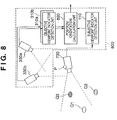
- a position/orientation measurement apparatus has an arrangement in which another objective viewpoint camera is added to the position/orientation measurement apparatus of the fifth embodiment, and a position/orientation calculation unit 820 that outputs the information of the position and orientation of the image sensing device 130 by a process different from that of the position/orientation calculation unit 320' is used in place of the position/orientation calculation unit 320'.
- Fig. 8 shows the arrangement of the position/orientation measurement apparatus according to this embodiment. Note that the same reference numerals and symbols in Fig. 8 denote the same parts as those in Figs. 1 and 3, and a description thereof will be omitted.
- a position/orientation measurement apparatus 800 according to this embodiment comprises objective viewpoint cameras 330a and 330b, a subjective viewpoint indicator detection unit 110, objective viewpoint indicator detection units 310a and 310b, and a position/orientation calculation unit 820, and is connected to an image sensing device 130 as an object to be measured.
- an objective viewpoint indicator P whose position on the objective viewpoint camera coordinate system is known is set. This indicator is preferably set so that it is always observed on images respectively captured by the objective viewpoint cameras 330a and 330b when the image sensing device 130 is located at respective points within the measurement range in which the position and orientation are to be measured.
- the objective viewpoint cameras 330a and 330b are fixed at positions at which they can always capture the objective viewpoint indicator P when the image sensing device 130 is located within the measurement range. Assume that the positions and orientations of the objective viewpoint cameras 330a and 330b on the world coordinate system are held in advance as known values.
- a plurality of subjective viewpoint indicators Q k are set as in the first embodiment. These indicators are preferably set so that the total number N of indicators observed on an image captured by the image sensing device 130 is always at least two when the image sensing device 130 is located at respective points within the measurement range in which the position and orientation are to be measured.
- three subjective viewpoint indicators Q 1 , Q 2 , and Q 3 are set, and two subjective viewpoint indicators Q 1 and Q 3 of them are included in the field of view of the image sensing device 130.
- the objective viewpoint indicator detection unit 310a receives an objective viewpoint image captured by the objective viewpoint camera 330a, detects the image coordinate of the objective viewpoint indicator P by the same process as in the prior art, and outputs its image coordinate u Pa and to the position/orientation calculation unit 820.
- the objective viewpoint indicator detection unit 310b receives an objective viewpoint image captured by the objective viewpoint camera 330b, detects the image coordinate of the objective viewpoint indicator P by the same process as in the prior art, and outputs its image coordinate u Pb and to the position/orientation calculation unit 820.
- the position/orientation calculation unit 820 calculates the position and orientation of the image sensing device 130 using the image coordinates u Qkn of the subjective viewpoint indicators Q kn and the image coordinates u Pa and u Pb of the objective viewpoint indicator P as inputs, and outputs the calculated position and orientation.
- the subjective viewpoint indicator detection unit 110, objective viewpoint indicator detection units 310a and 310b, and position/orientation calculation unit 820 shown in Fig. 8 may be handled as independent devices, or their functions may be implemented by installing them as software programs in one or a plurality of computers and executing these programs by a CPU of each computer.
- the respective units are handled as software programs which can run on a single computer.
- the basic arrangement of this computer is that shown in Fig. 10.
- Fig. 9 is a flow chart showing the process for calculating parameters indicating the position and orientation of the image sensing device 130, which is implemented when the CPU 1001 executes a software program of the position/orientation calculation unit 820.
- the software programs of the subjective viewpoint indicator detection unit 110, objective viewpoint indicator detection units 310a and 310b, and position/orientation calculation unit 820 have already been loaded onto the RAM 1002 prior to the following process.
- step S9000 the position/orientation calculation unit 820 receives the image coordinates u Pa and u Pb of the objective viewpoint indicator P detected by the objective viewpoint indicator detection units 310a and 310b.
- step S9010 the position/orientation calculation unit 820 calculates a position x W P of the objective viewpoint indicator P using the image coordinates u Pa and u Pb on the basis of the principle of triangulation.
- step S9020 the position/orientation calculation unit 820 sets an appropriate initial value (estimated value of the orientation) in the state vector s. For example, s derived in the process of the previous frame (time t k-1 ) may be used as the initial value, or a value predicted based on a change in derived value from old "s"s may be set.
- step S9030 the position/orientation calculation unit 820 receives the image coordinates u Qkn and identifiers k n of the respective subjective viewpoint indicators Q kn detected by the subjective viewpoint indicator detection unit 110.
- the position/orientation calculation unit 820 checks in step S9040 if the number of input subjective, viewpoint indicators is two or more. If the total number N of indicators is less than 2, the flow jumps to step S9110 while skipping an update process of s implemented in steps S9050 to S9100.
- step S9050 the position/orientation calculation unit 820 calculates estimated values u Qkn * of the image coordinates of the respective subjective viewpoint indicators Q kn on the basis of equations (1) to (4).
- R WC (s) is a rotation matrix which represents the orientation of the image sensing device 130 on the world coordinate system, and is defined by equation (24).
- step S9060 the position/orientation calculation unit 820 calculates an error ⁇ u Qkn between the estimated value u Qkn* and actually measured value u Qkn of the image coordinate of each subjective viewpoint indicator Q kn on the basis of equation (5).
- step S9080 the position/orientation calculation unit 820 defines a (2N)-dimensional error vector U by equation (7), and a matrix ⁇ (2N ⁇ 3) by equation (8), and calculates a correction value ⁇ s of the state vector s by equation (9).
- step S9090 the position/orientation calculation unit 820 corrects the state vector s using the correction value ⁇ s calculated in step S9080 by equation (10), and sets the corrected value as a new estimated value of s.
- the position/orientation calculation unit 820 determines in step S9100 whether or not the calculation converges, using some determination criteria, i.e., whether or not error vector U is smaller than a predetermined threshold value, whether or not the correction value ⁇ s is smaller than a predetermined threshold value, and so forth. If the calculation does not converge, the unit 820 repeats the process in step S9050 and subsequent steps using the corrected state vector s.
- the position/orientation calculation unit 820 outputs the information of the position and orientation of the image sensing device 130.
- the information of the position and orientation is output in the form of, e.g., a modeling conversion matrix calculated from s.
- the position of the image sensing device 130 on the world coordinate system may be calculated from the obtained s on the basis of equation (25), and may be output as 6-valued data together with s it self that indicates the orientation, or may be output after the orientation is converted into an Euler angle.
- the information of the position and orientation described by various other position/orientation description methods may be output.
- the position and orientation of the image sensing device 130 which can minimize errors of the subjective viewpoint indicators on the subjective viewpoint image can be obtained under the constraint condition that uses the positions of the objective viewpoint cameras 330a and 330b. Therefore, as in the fifth embodiment, the position/orientation measurement apparatus according to this embodiment functions more effectively than the first embodiment in a situation that the reliability of the information obtained from the objective viewpoint camera 330 is relatively higher than that obtained from the image sensing device 130, e.g., when a high-resolution objective viewpoint camera can be used, when a marker with very high detection precision can be used as only an objective viewpoint indicator, and so forth.
- the world coordinate x W P of the objective viewpoint indicator P is calculated based on the outputs from the two objective viewpoint cameras.
- other arbitrary means may be used in place of the objective viewpoint cameras in the sixth embodiment as long as they can measure a three-dimensional (3D) position of an arbitrary measurement point.
- the position/orientation measurement apparatus and position/orientation measurement method according to this embodiment will be described hereinafter.
- Fig. 12 shows the arrangement of the position/orientation measurement apparatus according to this embodiment. Note that the same reference numerals and symbols in Fig. 12 denote the same parts as those in Fig. 8, and a description thereof will be omitted.
- a position/orientation measurement apparatus 1200 according to this embodiment comprises a subjective viewpoint indicator detection unit 110, position sensor 1230, measurement point 1240, position input unit 1210, and position/orientation calculation unit 820', and is connected to an image sensing device 130 as an object to be measured.
- the position sensor 1230 measures the 3D position of a predetermined measurement point, and comprises, e.g., OPTOTRAK available from Northern Digital Inc. as an optical 3D position sensor.
- the measurement point 1240 is a point to be measured by the position sensor 1230, and comprises an infrared LED that flashes in accordance with a control signal from the position sensor 1230.
- the measurement point 1240 is attached to the image sensing device 130 in place of the objective viewpoint indicator P in the sixth embodiment.
- the measurement point 1240 is preferably set to always be included in the measurement range of the position sensor 1230 when the image sensing device 130 is located at respective points within the measurement range in which the position and orientation are to be measured.
- the position of the measurement point 1240 on the subjective viewpoint camera coordinate system is stored in the external storage device 1007 as known data, and is read out onto the RAM 1002 when it is used, as needed.
- the position input unit 1210 receives the 3D coordinate of the measurement point 1240 output from the position sensor 1230, and outputs it to the position/orientation calculation unit 820'.
- the position input unit 1210 converts the input coordinate into that on the world coordinate system, and then output the converted coordinate to the position/orientation calculation unit 820'.
- Coordinate conversion from the sensor coordinate system to the world coordinate system can be done by a known method if the position and orientation of the position sensor 1230 on the world coordinate system are given as known information.
- the position and orientation of the position sensor 1230 on the world coordinate system are stored as known information in the external storage device 1007, and are read out onto the RAM 1007 when they are used, as needed.
- the position/orientation calculation unit 820' calculates the position and orientation of the image sensing device 130 using the 3D coordinate of the measurement point 1240 input from the position input unit 1210, and the image coordinates u Qkn of subjective viewpoint indicators Q Kn input from the subjective viewpoint indicator detection unit 110, and outputs them.
- the operation of the position/orientation calculation unit 820' is substantially the same as that of the position/orientation calculation unit 820 in the sixth embodiment.
- the position/orientation calculation unit 820' has a step of receiving the position x W P of the measurement point 1240 on the world coordinate system from the position input unit 1210.
- the position of the measurement point 1240 on the world coordinate system is used as x W P in equation (25).
- the position and orientation of the image sensing device 130 which can minimize errors of the subjective viewpoint indicators on the subjective viewpoint image can be obtained under the constraint condition that uses the position of the measurement point 1240 obtained using the position sensor 1230.
- position & orientation measurement of the image sensing device 130 which can achieve both stability of the position precision obtained by use of the position sensor, and that of the alignment precision on an image obtained by use of the subjective viewpoint image, can be realized.
- any other sensors may be used as the position sensor 1230 as long as they can measure the 3D position of the measurement point.
- an ultrasonic sensor that measures the 3D position of an ultrasonic beacon e.g., IS-600 available from InterSense Inc.
- an ultrasonic beacon is attached to the image sensing device 130 as the measurement point 1240.
- this embodiment can also be applied to a case wherein the image sensing device 130 is mounted on an object to be measured to which the measurement point is attached, and the position and orientation of this object to be measured or the image sensing device 130 are to be measured, as can be seen from the above description.
- the position and orientation of the image sensing device 130 are to be measured, the position/orientation relationship between the image sensing device 130 and the object to be measured must be measured and held in advance in a memory.
- an optical sensor or ultrasonic sensor is used as the position sensor.
- a GPS Global Positioning System
- the position/orientation measurement apparatus and position/orientation measurement method according to this embodiment measures will be described hereinafter.
- Fig. 13 shows the arrangement of the position/orientation measurement apparatus according to this embodiment. Note that the same reference numerals and symbols in Fig. 13 denote the same parts as those in Fig. 12, and a description thereof will be omitted.
- a position/orientation measurement apparatus 1300 according to this embodiment comprises a subjective viewpoint indicator detection unit 110, GPS receiver 1330, position input unit 1310, and position/orientation calculation unit 1320, and is connected to an image sensing device 130 as an object to be measured.
- the GPS receiver 1330 is mounted on the image sensing device 130.
- the GPS receiver 1330 measures its own position (latitude, longitude, and altitude) on the earth by receiving signals from GPS satellites 1340a to 1340d, and outputs the measured position to the position input unit 1310.
- the measured values of only the latitude and longitude are often obtained. In such case, only the latitude and longitude are output.
- the position of the GPS receiver 1330 on the subjective viewpoint camera coordinate system is known.
- the position input unit 1310 receives the latitude, longitude, and altitude output from the GPS receiver 1330, converts them into a 3D coordinate (x P , y p , z P ) or two-dimensional (2D) coordinate (x P , y p ) on the world coordinate system by a known matrix conversion process, and outputs the converted position to the position/orientation calculation unit 1320.
- the position/orientation calculation unit 1320 calculates the position and orientation of the image sensing device 130 using the 3D or 2D coordinate of the GPS receiver 1330 input from the position input unit 1310, and the image coordinates u Qkn of subjective viewpoint indicators Q kn input from the subjective viewpoint indicator detection unit 110, and outputs them.
- the position/orientation calculation unit 1320 derives and outputs the position and orientation of the image sensing device 130 by the same process as that of the position/orientation calculation unit 820' in the sixth embodiment.
- the constraint formula of the line an equation corresponding to equation (22) in the fifth embodiment
- equation (22) in the fifth embodiment can be described by:
- the position and orientation of the image sensing device 130 which can minimize errors of the subjective viewpoint indicators on the subjective viewpoint image can be obtained under the constraint condition that uses the position obtained by the GPS receiver 1330.
- the GPS receiver 1330 can output a 3D coordinate
- an arrangement without any process branch upon obtaining only a 2D coordinate can be adopted. If it is assumed that the height of the image sensing device 130 is always constant (for example, if the image sensing device 130 is a built-in camera of an HMD, and its height is assumed to be that of the user), a fixed value may be used as the position in the height direction without using the altitude information obtained from the GPS receiver 1330.
- the correction value ⁇ s of the state vector is calculated based on the error vector U and matrix ⁇ using the steepest descent method given by equation (9).
- the correction value ⁇ s need not always be calculated by the steepest descent method.
- the correction value may be calculated using the LM method (Levenberg-Marquardt method) as a known numerical calculation method. That is, the essence of the present invention does not impair if any other numerical calculation methods are applied.
- a point feature i.e., an image coordinate of one point that represents a projected image of an indicator
- the indicators Q and P indicators from which such point feature can be extracted (to be referred to as point indicators hereinafter) are used.
- point indicators indicators from which such point feature can be extracted
- the above embodiments are not limited to the types of indicators, and the types of feature values associated with the image coordinates of indicators.
- markers having a specific geometric shape which are used in a known position/orientation measurement apparatus (Takahashi, I. Ishii, H. Makino, and M. Nakashizuka, "A high accuracy realtime 3D measuring method of rectangular marker position/orientation for VR interface by monocular vision", 3D Image Conference '96, pp. 167 - 172, 1996) may be used as subjective viewpoint indicators and/or objective viewpoint indicators.
- the world coordinates of the respective vertices of a rectangle are held as known values, and the image coordinates of the respective vertices are detected from an image as feature values associated with the image coordinates of the indicators, thus obtaining the same effect as that of the indicators in the embodiments.
- line features used in another known position/orientation measurement apparatus are used as feature values associated with the image coordinates of indicators, and indicators from which such line features can be extracted (to be referred to as line indicators hereinafter) may be used as subjective viewpoint indicators and/or objective viewpoint indicators.
- a distance of a line from an origin is used as a reference for evaluating an error
- the error vector U is formed by errors ⁇ d which are calculated based on detected values d from an image and estimated values d* from the state vector s
- the position and orientation may be measured by the same scheme as in the above embodiments.
- line and point indicators may be used together.
- one image sensing device 130 or subjective viewpoint camera 730 is used.
- a plurality of image sensing devices or subjective viewpoint cameras may be used as in the second embodiment.
- the objective viewpoint indicator P is set on the subjective viewpoint camera 730.
- the layout position of the subjective viewpoint indicator P is not limited to such specific position, and the same effect can be obtained if the indicator P is set on the object 710 to be measured.
- the positions of the objective viewpoint indicator, measurement point, and the GPS receiver are held as known values, and the differences from the position of the image sensing device 130 to be measured are considered.
- a simple arrangement that approximates these points to an identical point may be adopted.
- the essential feature lies in measurements of the position and orientation of the object to be measured by using geometric constraint conditions obtained from both the subjective and objective viewpoint images together, and the application range is not limited to the types of indicators, the use method of the constraint conditions, and the solution calculation method.
- the present invention can be applied to an apparatus comprising a single device or to system constituted by a plurality of devices.
- the invention can be implemented by supplying a software program, which implements the functions of the foregoing embodiments, directly or indirectly to a system or apparatus, reading the supplied program code with a computer of the system or apparatus, and then executing the program code.
- a software program which implements the functions of the foregoing embodiments
- reading the supplied program code with a computer of the system or apparatus, and then executing the program code.
- the mode of implementation need not rely upon a program.
- the program code installed in the computer also implements the present invention.
- the claims of the present invention also cover a computer program for the purpose of implementing the functions of the present invention.
- the program may be executed in any form, such as an object code, a program executed by an interpreter, or scrip data supplied to an operating system.
- Example of storage media that can be used for supplying the program are a floppy disk, a hard disk, an optical disk, a magneto-optical disk, a CD-ROM, a CD-R, a CD-RW, a magnetic tape, a non-volatile type memory card, a ROM, and a DVD (DVD-ROM and a DVD-R).
- a client computer can be connected to a website on the Internet using a browser of the client computer, and the computer program of the present invention or an automatically-installable compressed file of the program can be downloaded to a recording medium such as a hard disk.
- the program of the present invention can be supplied by dividing the program code constituting the program into a plurality of files and downloading the files from different websites.
- a WWW World Wide Web
- a storage medium such as a CD-ROM
- an operating system or the like running on the computer may perform all or a part of the actual processing so that the functions of the foregoing embodiments can be implemented by this processing.
- a CPU or the like mounted on the function expansion board or function expansion unit performs all or a part of the actual processing so that the functions of the foregoing embodiments can be implemented by this processing.
Applications Claiming Priority (4)
| Application Number | Priority Date | Filing Date | Title |
|---|---|---|---|
| JP2003004945 | 2003-01-10 | ||
| JP2003004945 | 2003-01-10 | ||
| JP2003323101 | 2003-09-16 | ||
| JP2003323101A JP4136859B2 (ja) | 2003-01-10 | 2003-09-16 | 位置姿勢計測方法 |
Publications (3)
| Publication Number | Publication Date |
|---|---|
| EP1437645A2 true EP1437645A2 (fr) | 2004-07-14 |
| EP1437645A3 EP1437645A3 (fr) | 2006-07-12 |
| EP1437645B1 EP1437645B1 (fr) | 2018-07-04 |
Family
ID=32510695
Family Applications (1)
| Application Number | Title | Priority Date | Filing Date |
|---|---|---|---|
| EP03258246.2A Expired - Fee Related EP1437645B1 (fr) | 2003-01-10 | 2003-12-30 | Méthode de mesure de position/orientation, et appareil de mesure de position/orientation |
Country Status (4)
| Country | Link |
|---|---|
| US (1) | US7092109B2 (fr) |
| EP (1) | EP1437645B1 (fr) |
| JP (1) | JP4136859B2 (fr) |
| CN (1) | CN100489833C (fr) |
Cited By (1)
| Publication number | Priority date | Publication date | Assignee | Title |
|---|---|---|---|---|
| EP1739622A2 (fr) | 2005-06-28 | 2007-01-03 | Cannon Kabushiki Kaisha | Identification d'un élément d'image avec deux caméras |
Families Citing this family (123)
| Publication number | Priority date | Publication date | Assignee | Title |
|---|---|---|---|---|
| JP4892792B2 (ja) * | 2001-07-04 | 2012-03-07 | コニカミノルタホールディングス株式会社 | 測定装置及び測定方法 |
| EP1398601A3 (fr) * | 2002-09-13 | 2014-05-07 | Canon Kabushiki Kaisha | Afficheur tête haute pour navigation dans un véhicule |
| JP4532856B2 (ja) * | 2003-07-08 | 2010-08-25 | キヤノン株式会社 | 位置姿勢計測方法及び装置 |
| US7353897B2 (en) * | 2003-07-23 | 2008-04-08 | Fernandez Dennis S | Telematic method and apparatus with integrated power source |
| JP4593968B2 (ja) * | 2004-05-14 | 2010-12-08 | キヤノン株式会社 | 位置姿勢計測方法および装置 |
| US7467061B2 (en) * | 2004-05-14 | 2008-12-16 | Canon Kabushiki Kaisha | Information processing method and apparatus for finding position and orientation of targeted object |
| JP4522140B2 (ja) * | 2004-05-14 | 2010-08-11 | キヤノン株式会社 | 指標配置情報推定方法および情報処理装置 |
| US7613361B2 (en) * | 2004-05-14 | 2009-11-03 | Canon Kabushiki Kaisha | Information processing method and device |
| WO2005119356A2 (fr) | 2004-05-28 | 2005-12-15 | Erik Jan Banning | Systeme interactif de pointage direct et de controle de presentation facile a deployer et procede d'etalonnage correspondant |
| US7024782B1 (en) * | 2004-10-28 | 2006-04-11 | Texas Instruments Incorporated | Electronic device compass operable irrespective of localized magnetic field |
| US7268893B2 (en) * | 2004-11-12 | 2007-09-11 | The Boeing Company | Optical projection system |
| JP4599184B2 (ja) * | 2005-02-02 | 2010-12-15 | キヤノン株式会社 | 指標配置計測方法、指標配置計測装置 |
| JP4859205B2 (ja) | 2005-02-04 | 2012-01-25 | キヤノン株式会社 | 情報処理装置、情報処理方法、及びプログラム |
| JP4767578B2 (ja) * | 2005-02-14 | 2011-09-07 | 株式会社岩根研究所 | 高精度cv演算装置と、この高精度cv演算装置を備えたcv方式三次元地図生成装置及びcv方式航法装置 |
| US7421113B2 (en) * | 2005-03-30 | 2008-09-02 | The Trustees Of The University Of Pennsylvania | System and method for localizing imaging devices |
| JP4785416B2 (ja) * | 2005-05-11 | 2011-10-05 | キヤノン株式会社 | 位置姿勢計測方法及び装置 |
| US9285897B2 (en) * | 2005-07-13 | 2016-03-15 | Ultimate Pointer, L.L.C. | Easily deployable interactive direct-pointing system and calibration method therefor |
| JP4914039B2 (ja) * | 2005-07-27 | 2012-04-11 | キヤノン株式会社 | 情報処理方法および装置 |
| WO2007014470A2 (fr) * | 2005-08-01 | 2007-02-08 | Resonant Medical Inc. | Systeme et procede de detection des derives dans les systemes de poursuite etalonnes |
| US20070070233A1 (en) * | 2005-09-28 | 2007-03-29 | Patterson Raul D | System and method for correlating captured images with their site locations on maps |
| US7847787B1 (en) | 2005-11-12 | 2010-12-07 | Navisense | Method and system for directing a control action |
| JP4459155B2 (ja) * | 2005-11-14 | 2010-04-28 | 株式会社東芝 | 光学式位置計測装置 |
| US7725288B2 (en) * | 2005-11-28 | 2010-05-25 | Navisense | Method and system for object control |
| US8494805B2 (en) | 2005-11-28 | 2013-07-23 | Orthosensor | Method and system for assessing orthopedic alignment using tracking sensors |
| US7620316B2 (en) * | 2005-11-28 | 2009-11-17 | Navisense | Method and device for touchless control of a camera |
| US7834850B2 (en) * | 2005-11-29 | 2010-11-16 | Navisense | Method and system for object control |
| US7414705B2 (en) * | 2005-11-29 | 2008-08-19 | Navisense | Method and system for range measurement |
| US8570274B1 (en) * | 2005-11-29 | 2013-10-29 | Navisense | Navigation device providing sensory feedback |
| US7834847B2 (en) * | 2005-12-01 | 2010-11-16 | Navisense | Method and system for activating a touchless control |
| US8814810B2 (en) * | 2005-12-01 | 2014-08-26 | Orthosensor Inc. | Orthopedic method and system for mapping an anatomical pivot point |
| US7788607B2 (en) * | 2005-12-01 | 2010-08-31 | Navisense | Method and system for mapping virtual coordinates |
| US8139029B2 (en) * | 2006-03-08 | 2012-03-20 | Navisense | Method and device for three-dimensional sensing |
| US8312479B2 (en) * | 2006-03-08 | 2012-11-13 | Navisense | Application programming interface (API) for sensory events |
| US8614669B2 (en) * | 2006-03-13 | 2013-12-24 | Navisense | Touchless tablet method and system thereof |
| US8334841B2 (en) * | 2006-03-13 | 2012-12-18 | Navisense | Virtual user interface method and system thereof |
| US8578282B2 (en) * | 2006-03-15 | 2013-11-05 | Navisense | Visual toolkit for a virtual user interface |
| JP5063023B2 (ja) * | 2006-03-31 | 2012-10-31 | キヤノン株式会社 | 位置姿勢補正装置、位置姿勢補正方法 |
| JP4812099B2 (ja) * | 2006-06-06 | 2011-11-09 | 独立行政法人産業技術総合研究所 | カメラ位置検出方法 |
| US8169404B1 (en) | 2006-08-15 | 2012-05-01 | Navisense | Method and device for planary sensory detection |
| US7978091B2 (en) * | 2006-08-24 | 2011-07-12 | Navisense | Method and device for a touchless interface |
| US8421642B1 (en) | 2006-08-24 | 2013-04-16 | Navisense | System and method for sensorized user interface |
| US7961173B2 (en) * | 2006-09-05 | 2011-06-14 | Navisense | Method and apparatus for touchless calibration |
| US8316324B2 (en) * | 2006-09-05 | 2012-11-20 | Navisense | Method and apparatus for touchless control of a device |
| US9451928B2 (en) | 2006-09-13 | 2016-09-27 | Elekta Ltd. | Incorporating internal anatomy in clinical radiotherapy setups |
| JP5036260B2 (ja) * | 2006-09-14 | 2012-09-26 | キヤノン株式会社 | 位置姿勢算出方法及び装置 |
| US8354997B2 (en) * | 2006-10-31 | 2013-01-15 | Navisense | Touchless user interface for a mobile device |
| US20080107305A1 (en) * | 2006-11-02 | 2008-05-08 | Northern Digital Inc. | Integrated mapping system |
| JP5403861B2 (ja) * | 2006-11-06 | 2014-01-29 | キヤノン株式会社 | 情報処理装置、情報処理方法 |
| US8904312B2 (en) * | 2006-11-09 | 2014-12-02 | Navisense | Method and device for touchless signing and recognition |
| US8793621B2 (en) * | 2006-11-09 | 2014-07-29 | Navisense | Method and device to control touchless recognition |
| JP4886560B2 (ja) * | 2007-03-15 | 2012-02-29 | キヤノン株式会社 | 情報処理装置、情報処理方法 |
| US8060841B2 (en) * | 2007-03-19 | 2011-11-15 | Navisense | Method and device for touchless media searching |
| US20080252595A1 (en) * | 2007-04-11 | 2008-10-16 | Marc Boillot | Method and Device for Virtual Navigation and Voice Processing |
| US20080284726A1 (en) * | 2007-05-17 | 2008-11-20 | Marc Boillot | System and Method for Sensory Based Media Control |
| JP4809291B2 (ja) * | 2007-06-01 | 2011-11-09 | 株式会社豊田中央研究所 | 計測装置及びプログラム |
| US20080306708A1 (en) * | 2007-06-05 | 2008-12-11 | Raydon Corporation | System and method for orientation and location calibration for image sensors |
| US10531858B2 (en) | 2007-07-20 | 2020-01-14 | Elekta, LTD | Methods and systems for guiding the acquisition of ultrasound images |
| WO2009012577A1 (fr) | 2007-07-20 | 2009-01-29 | Resonant Medical Inc. | Procédés et systèmes pour compenser des changements dans l'anatomie de patients de radiothérapie |
| US8135198B2 (en) | 2007-08-08 | 2012-03-13 | Resonant Medical, Inc. | Systems and methods for constructing images |
| JP4943270B2 (ja) * | 2007-08-09 | 2012-05-30 | 富士フイルム株式会社 | 三次元座標系の設定方法および装置 |
| US9189083B2 (en) | 2008-03-18 | 2015-11-17 | Orthosensor Inc. | Method and system for media presentation during operative workflow |
| JP5111210B2 (ja) * | 2008-04-09 | 2013-01-09 | キヤノン株式会社 | 画像処理装置、画像処理方法 |
| US8189738B2 (en) | 2008-06-02 | 2012-05-29 | Elekta Ltd. | Methods and systems for guiding clinical radiotherapy setups |
| JP2010134649A (ja) | 2008-12-03 | 2010-06-17 | Canon Inc | 情報処理装置、その処理方法及びプログラム |
| KR101017606B1 (ko) * | 2008-12-22 | 2011-02-28 | 한국항공우주연구원 | 단일영상을 이용한 자세각센서 삼차원 오정렬 보정방법 |
| JP5290864B2 (ja) * | 2009-05-18 | 2013-09-18 | キヤノン株式会社 | 位置姿勢推定装置及び方法 |
| US10542962B2 (en) | 2009-07-10 | 2020-01-28 | Elekta, LTD | Adaptive radiotherapy treatment using ultrasound |
| JP5393318B2 (ja) * | 2009-07-28 | 2014-01-22 | キヤノン株式会社 | 位置姿勢計測方法及び装置 |
| JP2011043986A (ja) * | 2009-08-21 | 2011-03-03 | Seiko Epson Corp | 光学式情報入力装置、光学式入力機能付き電子機器、および光学式情報入力方法 |
| US9011448B2 (en) * | 2009-12-31 | 2015-04-21 | Orthosensor Inc. | Orthopedic navigation system with sensorized devices |
| US20110172526A1 (en) * | 2010-01-12 | 2011-07-14 | Martin Lachaine | Feature Tracking Using Ultrasound |
| US9248316B2 (en) | 2010-01-12 | 2016-02-02 | Elekta Ltd. | Feature tracking using ultrasound |
| JP5297403B2 (ja) * | 2010-02-26 | 2013-09-25 | キヤノン株式会社 | 位置姿勢計測装置、位置姿勢計測方法、プログラムおよび記憶媒体 |
| JP5746477B2 (ja) | 2010-02-26 | 2015-07-08 | キヤノン株式会社 | モデル生成装置、3次元計測装置、それらの制御方法及びプログラム |
| JP5521727B2 (ja) * | 2010-04-19 | 2014-06-18 | ソニー株式会社 | 画像処理システム、画像処理装置、画像処理方法及びプログラム |
| JP5570316B2 (ja) * | 2010-06-17 | 2014-08-13 | キヤノン株式会社 | 撮像装置、その制御方法及びプログラム |
| JP5612916B2 (ja) | 2010-06-18 | 2014-10-22 | キヤノン株式会社 | 位置姿勢計測装置、その処理方法、プログラム、ロボットシステム |
| CN103425356B (zh) * | 2010-06-25 | 2016-07-13 | 原相科技股份有限公司 | 影像感测模块 |
| JP5624394B2 (ja) | 2010-07-16 | 2014-11-12 | キヤノン株式会社 | 位置姿勢計測装置、その計測処理方法及びプログラム |
| JP5496008B2 (ja) | 2010-08-06 | 2014-05-21 | キヤノン株式会社 | 位置姿勢計測装置、位置姿勢計測方法、およびプログラム |
| JP5671281B2 (ja) | 2010-08-20 | 2015-02-18 | キヤノン株式会社 | 位置姿勢計測装置、位置姿勢計測装置の制御方法及びプログラム |
| JP5661382B2 (ja) | 2010-08-31 | 2015-01-28 | キヤノン株式会社 | 画像表示装置 |
| WO2012095160A1 (fr) * | 2011-01-10 | 2012-07-19 | Trimble Ab | Procédé et système destinés à déterminer la position et l'orientation d'un instrument de mesure |
| US8970708B2 (en) * | 2011-05-23 | 2015-03-03 | The Johns Hopkins University | Automatic device alignment mechanism |
| JP5620343B2 (ja) * | 2011-06-20 | 2014-11-05 | 日本電信電話株式会社 | 物体座標系変換装置、物体座標系変換方法、及び物体座標系変換プログラム |
| DE112012004053T5 (de) | 2011-09-28 | 2014-07-31 | Canon K.K. | Bildverarbeitungsgerät, Bildverarbeitungsverfahren und Programm |
| KR101874895B1 (ko) * | 2012-01-12 | 2018-07-06 | 삼성전자 주식회사 | 증강 현실 제공 방법 및 이를 지원하는 단말기 |
| JP6004809B2 (ja) | 2012-03-13 | 2016-10-12 | キヤノン株式会社 | 位置姿勢推定装置、情報処理装置、情報処理方法 |
| CN102620656B (zh) * | 2012-04-16 | 2014-07-16 | 南京航空航天大学 | 一种航天器交会对接相对位姿测量方法 |
| CN102840825B (zh) * | 2012-08-21 | 2015-01-07 | 华北电力大学 | 一种质点定位系统及方法 |
| WO2014076774A1 (fr) * | 2012-11-14 | 2014-05-22 | 株式会社島津製作所 | Dispositif biométrique optique et dispositif de mesure de position l'utilisant |
| KR101956073B1 (ko) * | 2012-12-20 | 2019-03-08 | 삼성전자주식회사 | 시각적 인디케이터를 이용하여 사용자 인터페이스를 제공하는 3차원 입체 영상 표시 장치 및 그 장치를 이용한 방법 |
| DE102013206569B4 (de) | 2013-04-12 | 2020-08-06 | Siemens Healthcare Gmbh | Gestensteuerung mit automatisierter Kalibrierung |
| JP2014219738A (ja) * | 2013-05-01 | 2014-11-20 | 船井電機株式会社 | プロジェクタ |
| CN103307968B (zh) * | 2013-06-03 | 2016-11-02 | 西北工业大学 | 机器人承载平台姿态的检测方法 |
| JP6397269B2 (ja) | 2013-09-06 | 2018-09-26 | キヤノン株式会社 | 画像処理装置、画像処理方法 |
| EP3056854B1 (fr) * | 2013-09-30 | 2020-10-14 | National Institute of Advanced Industrial Science and Technology | Système de traitement d'image de marqueur |
| US20150098079A1 (en) | 2013-10-09 | 2015-04-09 | Hilti Aktiengesellschaft | System and method for camera based position and orientation measurement |
| JP6253368B2 (ja) * | 2013-11-25 | 2017-12-27 | キヤノン株式会社 | 三次元形状計測装置およびその制御方法 |
| US9747680B2 (en) | 2013-11-27 | 2017-08-29 | Industrial Technology Research Institute | Inspection apparatus, method, and computer program product for machine vision inspection |
| JP6393106B2 (ja) | 2014-07-24 | 2018-09-19 | キヤノン株式会社 | 画像処理装置、画像処理方法およびプログラム |
| US9808213B2 (en) | 2014-08-11 | 2017-11-07 | Canon Kabushiki Kaisha | Image processing apparatus, image processing method, medical image diagnostic system, and storage medium |
| CN104634246B (zh) * | 2015-02-03 | 2017-04-12 | 李安澜 | 目标空间坐标的浮动式立体视觉测量系统及测量方法 |
| EP3064898B1 (fr) * | 2015-03-04 | 2019-12-18 | Leica Geosystems AG | Appareil de mesure ayant une fonctionnalité de suivi de cible ou de visée fine |
| JP6971544B2 (ja) | 2015-08-06 | 2021-11-24 | キヤノン株式会社 | 画像処理装置、画像処理方法、およびプログラム |
| JP6590609B2 (ja) * | 2015-09-15 | 2019-10-16 | キヤノン株式会社 | 画像解析装置及び画像解析方法 |
| US10682911B2 (en) * | 2016-02-18 | 2020-06-16 | Sony Corporation | Active window for vehicle infomatics and virtual reality |
| JP6640643B2 (ja) * | 2016-04-08 | 2020-02-05 | 株式会社東芝 | 水中点検装置及び水中点検方法 |
| JP6840481B2 (ja) | 2016-07-19 | 2021-03-10 | キヤノン株式会社 | 画像処理装置および画像処理方法 |
| JP6711715B2 (ja) | 2016-07-19 | 2020-06-17 | キヤノン株式会社 | 画像処理装置および画像処理方法 |
| JP6557640B2 (ja) * | 2016-07-22 | 2019-08-07 | 日本電信電話株式会社 | カメラキャリブレーション装置、カメラキャリブレーション方法及びカメラキャリブレーションプログラム |
| JP2018107695A (ja) * | 2016-12-27 | 2018-07-05 | フォーブ インコーポレーテッド | 推定システム、推定方法及び推定プログラム |
| JP2018110615A (ja) | 2017-01-06 | 2018-07-19 | キヤノン株式会社 | 画像処理装置および画像処理方法 |
| CN108332741B (zh) * | 2017-01-18 | 2021-09-14 | 宏达国际电子股份有限公司 | 定位装置及方法 |
| JP6934734B2 (ja) | 2017-03-17 | 2021-09-15 | キヤノン株式会社 | 画像処理装置、画像処理装置の制御方法およびプログラム |
| WO2019130827A1 (fr) | 2017-12-25 | 2019-07-04 | キヤノン株式会社 | Appareil de traitement d'image et son procédé de commande |
| JP7058585B2 (ja) | 2017-12-25 | 2022-04-22 | キヤノン株式会社 | 画像処理装置およびその制御方法 |
| US10690525B2 (en) | 2018-01-03 | 2020-06-23 | General Electric Company | Systems and methods associated with unmanned aerial vehicle targeting accuracy |
| JP7124424B2 (ja) * | 2018-05-02 | 2022-08-24 | オムロン株式会社 | 3次元形状計測システム及び計測時間設定方法 |
| CN112204341B (zh) * | 2018-06-01 | 2023-12-05 | 松下电器(美国)知识产权公司 | 三维数据编码方法、三维数据解码方法、三维数据编码装置、以及三维数据解码装置 |
| JP2022089269A (ja) * | 2020-12-04 | 2022-06-16 | 株式会社日立製作所 | キャリブレーション装置およびキャリブレーション方法 |
| CN116150520B (zh) * | 2022-12-30 | 2023-11-14 | 联通智网科技股份有限公司 | 一种数据处理方法、装置、设备和存储介质 |
| CN117630993B (zh) * | 2024-01-15 | 2024-04-12 | 华中科技大学 | 一种基于sair多快拍的rfi源地理定位方法 |
Citations (2)
| Publication number | Priority date | Publication date | Assignee | Title |
|---|---|---|---|---|
| US6064749A (en) * | 1996-08-02 | 2000-05-16 | Hirota; Gentaro | Hybrid tracking for augmented reality using both camera motion detection and landmark tracking |
| EP1213686A2 (fr) * | 2000-11-30 | 2002-06-12 | Mixed Reality Systems Laboratory Inc. | Traitement d' information et presentation de réalité mélangé |
Family Cites Families (12)
| Publication number | Priority date | Publication date | Assignee | Title |
|---|---|---|---|---|
| WO1996024216A1 (fr) * | 1995-01-31 | 1996-08-08 | Transcenic, Inc. | Photographie referencee dans l'espace |
| US5727093A (en) | 1995-02-07 | 1998-03-10 | Canon Kabushiki Kaisha | Image processing method and apparatus therefor |
| DE69622900T2 (de) | 1995-03-17 | 2003-04-10 | Canon Kk | Verfahren und Gerät zur dreidimensionalen Bildverarbeitung |
| JPH09323280A (ja) | 1996-06-04 | 1997-12-16 | Nippon Telegr & Teleph Corp <Ntt> | マニピュレータの制御方法及びシステム |
| US5889550A (en) * | 1996-06-10 | 1999-03-30 | Adaptive Optics Associates, Inc. | Camera tracking system |
| GB2329292A (en) * | 1997-09-12 | 1999-03-17 | Orad Hi Tec Systems Ltd | Camera position sensing system |
| JP3467017B2 (ja) | 2000-11-30 | 2003-11-17 | キヤノン株式会社 | 位置姿勢の決定方法及び装置並びに記憶媒体 |
| JP2003107340A (ja) * | 2001-09-27 | 2003-04-09 | Canon Inc | 測光測距用固体撮像装置及びそれを用いた撮像装置 |
| JP3805231B2 (ja) | 2001-10-26 | 2006-08-02 | キヤノン株式会社 | 画像表示装置及びその方法並びに記憶媒体 |
| JP4072330B2 (ja) | 2001-10-31 | 2008-04-09 | キヤノン株式会社 | 表示装置および情報処理方法 |
| JP3796449B2 (ja) | 2002-01-31 | 2006-07-12 | キヤノン株式会社 | 位置姿勢決定方法および装置並びにコンピュータプログラム |
| EP1349114A3 (fr) | 2002-03-19 | 2011-06-15 | Canon Kabushiki Kaisha | Appareil d'étalonnage de capteur, méthode d'étalonnage de capteur, programme, support d'enregistrement, méthode de traitement d'information et appareil de traitement d'information |
-
2003
- 2003-09-16 JP JP2003323101A patent/JP4136859B2/ja not_active Expired - Fee Related
- 2003-12-30 EP EP03258246.2A patent/EP1437645B1/fr not_active Expired - Fee Related
-
2004
- 2004-01-08 US US10/752,487 patent/US7092109B2/en active Active
- 2004-01-12 CN CNB2004100005302A patent/CN100489833C/zh not_active Expired - Fee Related
Patent Citations (2)
| Publication number | Priority date | Publication date | Assignee | Title |
|---|---|---|---|---|
| US6064749A (en) * | 1996-08-02 | 2000-05-16 | Hirota; Gentaro | Hybrid tracking for augmented reality using both camera motion detection and landmark tracking |
| EP1213686A2 (fr) * | 2000-11-30 | 2002-06-12 | Mixed Reality Systems Laboratory Inc. | Traitement d' information et presentation de réalité mélangé |
Non-Patent Citations (5)
| Title |
|---|
| RONALD T AZUMA: "A Survey of Augmented Reality" PRESENCE, CAMBRIDGE, MA, US, August 1997 (1997-08), pages 1-48, XP002254668 ISSN: 1054-7460 * |
| STATE A ET AL: "SUPERIOR AUGMENTED REALITY REGISTRATION BY INTEGRATING LANDMARK TRACKING AND MAGNETIC TRACKING" COMPUTER GRAPHICS PROCEEDINGS 1996 (SIGGRAPH). NEW ORLEANS, AUG. 4 - 9, 1996, COMPUTER GRAPHICS PROCEEDINGS (SIGGRAPH), NEW YORK, NY : ACM, US, 4 August 1996 (1996-08-04), pages 429-438, XP000682759 * |
| THOMAS G A ET AL: "A versatile camera position measurement system for virtual reality TV production" INTERNATIONAL BROADCASTING CONVENTION, LONDON, GB, 6 September 1997 (1997-09-06), pages 284-289, XP002080724 * |
| WARD M., ET AL: "A Demonstrated Optical Tracker With Scalable Work Area for Head-Mounted Display Systems"[Online] 1992, XP002382938 Retrieved from the Internet: URL:http://www.cs.unc.edu/~welch/media/pdf /hybrid.pdf> [retrieved on 2006-05-24] * |
| WELCH G., ET AL: "High-Performance Wide-Area Optical Tracking The HiBall Tracking System"[Online] February 2001 (2001-02), XP002382939 Retrieved from the Internet: URL:http://www.cs.unc.edu/~welch/media/pdf /PRES101_Welch_etal.pdf> [retrieved on 2006-05-29] * |
Cited By (2)
| Publication number | Priority date | Publication date | Assignee | Title |
|---|---|---|---|---|
| EP1739622A2 (fr) | 2005-06-28 | 2007-01-03 | Cannon Kabushiki Kaisha | Identification d'un élément d'image avec deux caméras |
| EP1739622A3 (fr) * | 2005-06-28 | 2012-03-14 | Canon Kabushiki Kaisha | Identification d'un élément d'image avec deux caméras |
Also Published As
| Publication number | Publication date |
|---|---|
| CN1517902A (zh) | 2004-08-04 |
| US7092109B2 (en) | 2006-08-15 |
| JP2004233334A (ja) | 2004-08-19 |
| EP1437645B1 (fr) | 2018-07-04 |
| CN100489833C (zh) | 2009-05-20 |
| US20040176925A1 (en) | 2004-09-09 |
| EP1437645A3 (fr) | 2006-07-12 |
| JP4136859B2 (ja) | 2008-08-20 |
Similar Documents
| Publication | Publication Date | Title |
|---|---|---|
| EP1437645B1 (fr) | Méthode de mesure de position/orientation, et appareil de mesure de position/orientation | |
| JP4976756B2 (ja) | 情報処理方法および装置 | |
| US9953461B2 (en) | Navigation system applying augmented reality | |
| US8350897B2 (en) | Image processing method and image processing apparatus | |
| JP4708752B2 (ja) | 情報処理方法および装置 | |
| US10068344B2 (en) | Method and system for 3D capture based on structure from motion with simplified pose detection | |
| US8335400B2 (en) | Information processing method and information processing apparatus | |
| JP4757142B2 (ja) | 撮影環境校正方法及び情報処理装置 | |
| EP1596332B1 (fr) | Méthode et appareil de traitement d'information pour trouver la position et l'orientation d'un objet visé | |
| JP4593968B2 (ja) | 位置姿勢計測方法および装置 | |
| EP1596330A2 (fr) | Estimation de position et d'orientation de marqueurs dans des images numériques | |
| US7630555B2 (en) | Position and orientation measuring method and apparatus | |
| WO2015068470A1 (fr) | Dispositif de mesure de forme 3d, procédé de mesure de forme 3d, et programme de mesure de forme 3d | |
| JP2007064684A (ja) | マーカ配置補助方法及び装置 | |
| WO2020195875A1 (fr) | Dispositif et procédé de traitement d'informations, et programme | |
| JP4566786B2 (ja) | 位置姿勢計測方法および情報処理装置 | |
| JP5726024B2 (ja) | 情報処理方法および装置 | |
| JP2008292407A (ja) | 情報処理方法及び情報処理装置 | |
| JP2008046749A (ja) | 画像処理方法および装置 | |
| JP6109213B2 (ja) | 情報処理装置および方法、プログラム | |
| JP4926598B2 (ja) | 情報処理方法、情報処理装置 | |
| JP4612804B2 (ja) | 位置姿勢計測方法および情報処理装置 | |
| JP2004233201A (ja) | 位置姿勢計測方法 | |
| KR20160099981A (ko) | 패턴을 가지는 입체표식기를 이용한 복수 사용자를 포함하는 쌍방향 인식이 가능한 가상현실 장치 | |
| JP4810403B2 (ja) | 情報処理装置、情報処理方法 |
Legal Events
| Date | Code | Title | Description |
|---|---|---|---|
| PUAI | Public reference made under article 153(3) epc to a published international application that has entered the european phase |
Free format text: ORIGINAL CODE: 0009012 |
|
| AK | Designated contracting states |
Kind code of ref document: A2 Designated state(s): AT BE BG CH CY CZ DE DK EE ES FI FR GB GR HU IE IT LI LU MC NL PT RO SE SI SK TR |
|
| AX | Request for extension of the european patent |
Extension state: AL LT LV MK |
|
| PUAL | Search report despatched |
Free format text: ORIGINAL CODE: 0009013 |
|
| AK | Designated contracting states |
Kind code of ref document: A3 Designated state(s): AT BE BG CH CY CZ DE DK EE ES FI FR GB GR HU IE IT LI LU MC NL PT RO SE SI SK TR |
|
| AX | Request for extension of the european patent |
Extension state: AL LT LV MK |
|
| 17P | Request for examination filed |
Effective date: 20070112 |
|
| AKX | Designation fees paid |
Designated state(s): DE FR GB IT NL |
|
| 17Q | First examination report despatched |
Effective date: 20070614 |
|
| REG | Reference to a national code |
Ref country code: DE Ref legal event code: R079 Ref document number: 60351289 Country of ref document: DE Free format text: PREVIOUS MAIN CLASS: G06F0003033000 Ipc: G01B0011000000 |
|
| RIC1 | Information provided on ipc code assigned before grant |
Ipc: G06F 3/03 20060101ALI20171218BHEP Ipc: G01B 11/00 20060101AFI20171218BHEP |
|
| GRAP | Despatch of communication of intention to grant a patent |
Free format text: ORIGINAL CODE: EPIDOSNIGR1 |
|
| INTG | Intention to grant announced |
Effective date: 20180131 |
|
| GRAS | Grant fee paid |
Free format text: ORIGINAL CODE: EPIDOSNIGR3 |
|
| GRAA | (expected) grant |
Free format text: ORIGINAL CODE: 0009210 |
|
| AK | Designated contracting states |
Kind code of ref document: B1 Designated state(s): DE FR GB IT NL |
|
| REG | Reference to a national code |
Ref country code: GB Ref legal event code: FG4D |
|
| REG | Reference to a national code |
Ref country code: DE Ref legal event code: R096 Ref document number: 60351289 Country of ref document: DE |
|
| REG | Reference to a national code |
Ref country code: NL Ref legal event code: MP Effective date: 20180704 |
|
| PG25 | Lapsed in a contracting state [announced via postgrant information from national office to epo] |
Ref country code: NL Free format text: LAPSE BECAUSE OF FAILURE TO SUBMIT A TRANSLATION OF THE DESCRIPTION OR TO PAY THE FEE WITHIN THE PRESCRIBED TIME-LIMIT Effective date: 20180704 |
|
| RIC2 | Information provided on ipc code assigned after grant |
Ipc: G01B 11/00 20060101AFI20171218BHEP Ipc: G06F 3/03 20060101ALI20171218BHEP |
|
| REG | Reference to a national code |
Ref country code: DE Ref legal event code: R097 Ref document number: 60351289 Country of ref document: DE |
|
| PG25 | Lapsed in a contracting state [announced via postgrant information from national office to epo] |
Ref country code: IT Free format text: LAPSE BECAUSE OF FAILURE TO SUBMIT A TRANSLATION OF THE DESCRIPTION OR TO PAY THE FEE WITHIN THE PRESCRIBED TIME-LIMIT Effective date: 20180704 |
|
| PGFP | Annual fee paid to national office [announced via postgrant information from national office to epo] |
Ref country code: DE Payment date: 20190228 Year of fee payment: 16 |
|
| PLBE | No opposition filed within time limit |
Free format text: ORIGINAL CODE: 0009261 |
|
| STAA | Information on the status of an ep patent application or granted ep patent |
Free format text: STATUS: NO OPPOSITION FILED WITHIN TIME LIMIT |
|
| 26N | No opposition filed |
Effective date: 20190405 |
|
| GBPC | Gb: european patent ceased through non-payment of renewal fee |
Effective date: 20181230 |
|
| PG25 | Lapsed in a contracting state [announced via postgrant information from national office to epo] |
Ref country code: FR Free format text: LAPSE BECAUSE OF NON-PAYMENT OF DUE FEES Effective date: 20181231 |
|
| PG25 | Lapsed in a contracting state [announced via postgrant information from national office to epo] |
Ref country code: GB Free format text: LAPSE BECAUSE OF NON-PAYMENT OF DUE FEES Effective date: 20181230 |
|
| REG | Reference to a national code |
Ref country code: DE Ref legal event code: R119 Ref document number: 60351289 Country of ref document: DE |
|
| PG25 | Lapsed in a contracting state [announced via postgrant information from national office to epo] |
Ref country code: DE Free format text: LAPSE BECAUSE OF NON-PAYMENT OF DUE FEES Effective date: 20200701 |