EP1596332B1 - Méthode et appareil de traitement d'information pour trouver la position et l'orientation d'un objet visé - Google Patents
Méthode et appareil de traitement d'information pour trouver la position et l'orientation d'un objet visé Download PDFInfo
- Publication number
- EP1596332B1 EP1596332B1 EP05252971.6A EP05252971A EP1596332B1 EP 1596332 B1 EP1596332 B1 EP 1596332B1 EP 05252971 A EP05252971 A EP 05252971A EP 1596332 B1 EP1596332 B1 EP 1596332B1
- Authority
- EP
- European Patent Office
- Prior art keywords
- orientation
- indices
- image
- bird
- eye view
- Prior art date
- Legal status (The legal status is an assumption and is not a legal conclusion. Google has not performed a legal analysis and makes no representation as to the accuracy of the status listed.)
- Expired - Fee Related
Links
Images


Classifications
-
- G—PHYSICS
- G06—COMPUTING; CALCULATING OR COUNTING
- G06T—IMAGE DATA PROCESSING OR GENERATION, IN GENERAL
- G06T7/00—Image analysis
- G06T7/70—Determining position or orientation of objects or cameras
- G06T7/73—Determining position or orientation of objects or cameras using feature-based methods
- G06T7/74—Determining position or orientation of objects or cameras using feature-based methods involving reference images or patches
-
- G—PHYSICS
- G06—COMPUTING; CALCULATING OR COUNTING
- G06T—IMAGE DATA PROCESSING OR GENERATION, IN GENERAL
- G06T7/00—Image analysis
- G06T7/30—Determination of transform parameters for the alignment of images, i.e. image registration
- G06T7/33—Determination of transform parameters for the alignment of images, i.e. image registration using feature-based methods
Definitions
- the present invention relates to an apparatus and method for measuring the position and orientation of an object.
- An image display apparatus for displaying mixed reality is realized by so-called "video see-through” in which a virtual space image (e.g., a virtual object drawn by computer graphics, text information, etc.), generated in response to the position and orientation of an imaging device such as a video camera, is drawn so as to be superimposed on a real space image captured by the imaging device, whereby a superimposition image is displayed.
- a virtual space image e.g., a virtual object drawn by computer graphics, text information, etc.
- the image display apparatus can also be realized by so-called "optical see-through” in which a virtual space image, generated in response to the position and orientation of an observer's viewpoint, is displayed on an optical see-through display mounted on the head of the observer.
- the estimated position and orientation is also used as initial values for calculation of a position and orientation based on an image, or as a rough position and orientation even if no indices are found (e.g., Hirofumi FUJII, Masayuki KANBARA, Hidehiko IWASA, Haruo TAKEMURA, Naokazu YOKOYA, "Kakuchogenjitsu-notameno Jairosensa-wo Heiyoshita Sutereopedia-niyoru Ichiawase (registration with a stereo camera by jointly using a gyro sensor for augmented reality)", Denshi Joho Tsushin Gakkai (Institute of Electronics, Information and Communication Engineers) Gijutsu Hokoku (Technical report) PRMU99-192 (Shingaku Giho (Technical Report of IEICE), vol. 99, no. 574, pp. 1-8 )".
- XP010662795 "Robust vision-based registration utilizing bird's-eye view with user's view", Proceedings of the Second IEEE and ACM International Symposium on Mixed and Augmented Reality , discloses vision based registration systems utilizing not only cameras on a user's head-mounted display but also a bird's-eye view camera that observes the user from an objective view point.
- XP010568049 "A hybrid registration method for outdoor augmented reality", Proceedings IEEE and ACM International Symposium , discloses a registration method for outdoor wearable AR systems.
- the method disclosed uses a high precision gyroscope, which can measure 3DOF angle of head direction accurately, but with some drift error.
- the drift problem is solved with a vision based drift-compensation algorithm, which tracks natural features in the outdoor environment, such as landmarks, from images captured by a camera on a HMD.
- a position-and-orientation measuring apparatus measures the position and orientation of an arbitrary targeted object to be measured.
- the position-and-orientation measuring apparatus according to the illustrative example and a position-and-orientation measuring method therefor are described below.
- Fig. 1 shows the configuration of a position-and-orientation measuring apparatus 10 according to the first illustrative example.
- the position-and-orientation measuring apparatus 10 includes bird's-eye view cameras 18a, 18b, 18c, and 18d, an image input unit 16, a data storage unit 17, an index detecting unit 11, an orientation sensor 14, an orientation predicting unit 15, and a position-orientation calculating unit 12.
- the position-and-orientation measuring apparatus 10 is connected to a targeted object 13 to be measured.
- a position-and-orientation measuring apparatus measures the position and orientation of an arbitrary targeted object to be measured.
- the position-and-orientation measuring apparatus according to the embodiment and a position-and-orientation measuring method therefor are described below.
- Fig. 1 shows the configuration of a position-and-orientation measuring apparatus 10 according to the first embodiment.
- the position-and-orientation measuring apparatus 10 includes bird's-eye view cameras 18a, 18b, 18c, and 18d, an image input unit 16, a data storage unit 17, an index detecting unit 11, an orientation sensor 14, an orientation predicting unit 15, and a position-orientation calculating unit 12.
- the position-and-orientation measuring apparatus 10 is connected to a targeted object 13 to be measured.
- the object coordinate system is defined by an origin and three perpendicularly intersecting axes on the targeted object 13.
- these indices be set so that, when the targeted object 13 is positioned at each point in a measurement range in which position and orientation measurement is to be performed, the total number of (physical) indices observed in bird's-eye view images acquired by the bird's-eye view cameras 18a, 18b, 18c, and 18d be at least two.
- the example shown in Fig. 1 shows a state in which two indices P 1 and P 2 are set and index P 1 is included in a field of view of the bird's-eye view camera 18c and index P 2 is included in fields of view of the bird's-eye view cameras 18c and 18d.
- Indices P k may be formed of, for example, spherical or circular markers having different colors, or may be formed of feature points such as natural features having different texture features. Indices P k may have any index form if coordinates of a projected image in a captured image can be detected and each index can be identified. In addition, indices P k may be deliberately set or may have natural shapes which are formed without being deliberately set.
- the bird's-eye view cameras 18a, 18b, 18c, and 18d are fixedly disposed at such positions that, when the targeted object 13 is positioned in the measurement range, one of the bird's-eye view cameras 18a, 18b, 18c, and 18d can capture the image of the targeted object 13.
- a term "bird's-eye view camera” to indicate the camera that observes the targeted object 13 from a third-persons viewpoint; the position of the camera is not limited to the "bird's-eye” position.
- the positions and orientations of the bird's-eye view cameras 18a, 18b, 18c, and 18d in the world coordinate system should be stored beforehand as known values in the data storage unit 17. Images (hereinafter referred to as "bird's-eye view images”) output by the bird's-eye view cameras 18a, 18b, 18c, and 18d are input to the image input unit 16.
- the input images are converted into digital data by the image input unit 16, and are stored in the data storage unit 17.
- the orientation sensor 14 is mounted on the targeted object 13.
- the orientation sensor 14 measures its present orientation and outputs measured values to the orientation predicting unit 15.
- the orientation sensor 14 is a sensor unit based on angular rate sensors such as gyroscopes, and is formed of, for example, a TISS-5-40 made by Tokimec Inc. in Japan, or an InertiaCube2 made by InterSense Inc. in the United States.
- a measured orientation value obtained by the above sensor is an orientation having an error, which differs from the actual orientation.
- the above orientation sensor has, as components, some acceleration sensors for observing the gravitational direction of the earth, and has a function of canceling accumulation of drift error in the direction of an angle of inclination.
- the above orientation sensor has a property of producing no drift error in the direction of the angle of inclination (pitch angle and roll angle).
- the above sensor has drift error that is accumulated with the lapse of time concerning an angle around the gravitational axis, that is an azimuth (yaw) angle direction.
- the orientation predicting unit 15 receives azimuth-drift-error correction value ⁇ from the data storage unit 17, predicts the orientation of the targeted object 13 by correcting the measured orientation value input from the orientation sensor 14, and outputs the predicted orientation to the data storage unit 17.
- Bird's-eye view images are input from the data storage unit 17 to the index detecting unit 11, and the image coordinates of indices in the input images are detected.
- the indices are formed of markers having different colors
- regions that correspond to the markers' colors are detected from the bird's-eye view images, and their barycentric positions are used as detected coordinates of the indices.
- the positions of the indices are detected by implementing, on the bird's-eye view images, template matching based on template images for the indices which are stored beforehand as known information.
- the calculation load required for index detection can be reduced and false detection and false identification of indices can be reduced.
- the index detecting unit 11 outputs the image coordinates of the detected indices and their identifiers to the data storage unit 17.
- the coordinates of indices P kxm detected for the images are represented by u a Pkam , u b Pkbm , u c Pkcm , u d Pkdm , respectively.
- the identifiers of bird's-eye view cameras which photograph these index identifiers, and image coordinates u e Pkc1 , u c Pkc2 , and u d Pkd1 which correspond to the identifiers are output.
- the predicted value of the orientation of the targeted object 13 From the data storage unit 17, the predicted value of the orientation of the targeted object 13, and sets of image coordinates u a Pkam , u b Pkbm , u c Pkcm , and u d Pkdm of the indices detected by the index detecting unit 11 and corresponding object coordinates (coordinate values in the object coordinate system) x C P kam , x C Pkbm , x C Pkcm , and x C Pkdm are input to position-orientation calculating unit 12.
- the position-orientation calculating unit 12 calculates the position and orientation of the targeted object 13 based on the above information, and outputs the calculated position and orientation to the exterior through an interface (not shown).
- the position-orientation calculating unit 12 outputs the calculated position of the targeted object 13 to the data storage unit 17, and updates the azimuth-drift-error correction value stored in the data storage unit 17 by using an update value of the azimuth-drift-error correction value of the orientation sensor 14 which is derived from the process of calculating the position and orientation of the targeted object 13.
- the data storage unit 17 stores the azimuth-drift-error correction value, the images input from the image input unit 16, the predicted value of the orientation input from the orientation predicting unit 15, the calculated value of the position input from the position-orientation calculating unit 12, the image coordinates and identifiers of the indices input from the index detecting unit 11, and data such as object coordinates (coordinate values in the object coordinate system) of the indices, and camera parameters of the bird's-eye view cameras 18a, 18b, 18c, and 18d, which are known values.
- the data storage unit 17 inputs and outputs the stored data, if necessary.
- the image input unit 16, data storage unit 17, index detecting unit 11, orientation predicting unit 15, and position-orientation calculating unit 12, shown in Fig. 1 may be treated as separate devices.
- the functions of the image input unit 16, data storage unit 17, index detecting unit 11, orientation predicting unit 15, and position-orientation calculating unit 12, shown in Fig. 1 may be implemented by installing software into one or more computers and allowing a central processing unit (CPU) of each computer to execute the installed software.
- CPU central processing unit
- each of the image input unit 16, data storage unit 17, index detecting unit 11, orientation predicting unit 15, and position-orientation calculating unit 12, shown in Fig. 1 is treated as software to be executed by a single computer.
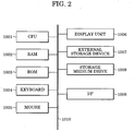
- Fig. 2 is a block diagram showing the basic configuration of a computer that executes, as software, each of the image input unit 16, data storage unit 17, index detecting unit 11, orientation predicting unit 15, and position-orientation calculating unit 12, shown in Fig. 1 .
- a CPU 1001 controls the entirety of the computer by using programs and data stored in a random access memory (RAM) 1002 and a read-only memory (ROM) 1003.
- RAM random access memory
- ROM read-only memory
- the RAM 1002 includes an area for temporarily storing a program and data loaded from the external storage device 1007 or the storage medium drive 1008, and also includes the work area required for the CPU 1001 to perform various types of processing.
- the function of the data storage unit 17 is realized by the RAM 1002.
- the ROM 1003 stores, in general, a program stored for the computer and setting data.
- a keyboard 1004 and a mouse 1005 are used by an operator to input various instructions to the CPU 1001.
- a display unit 1006 is formed of a cathode-ray tube, a liquid crystal display screen, or the like, and can display, for example, a message, etc., which are to be displayed for position and orientation measurement of the targeted object 13.
- the external storage device 1007 functions as a large volume information storage device, and stores an operating system, software programs, etc. In the description of the first illustrative example, information that is described as known is stored in the external storage device 1007, and is loaded into the RAM 1002, if necessary.
- a storage medium drive 1008 reads a program or data stored in a recording medium such as CD-ROM or DVD-ROM in response to an instruction of the CPU 1001, and outputs the read program or data to the RAM 1002 or the external storage device 1007.
- An interface 1009 includes an analog video port or digital input/output port, such as the IEEE 1394 standard, for connecting the bird's-eye view cameras 18, RS-233C or USB serial port for connecting the orientation sensor 14, and the Ethernet port for outputting the position and orientation of the targeted object 13 to the exterior.
- Input data is loaded into the RAM 1002 through the interface 1009. Part of the function of the image input unit 16 is realized by the interface 1009.
- a bus 1010 is used to connect the CPU 1001, the RAM 1002, the ROM 1003, the keyboard 1004, the mouse 1005, the display unit 1006, the external storage device 1007, the storage medium drive 1008, and the interface 1009.
- Fig. 3 is a flowchart showing a process of the orientation predicting unit 15. This process is performed such that the CPU 1001 executes the software program of the orientation predicting unit 15. In a stage prior to implementation of the following process, program code in accordance with the flowchart should be loaded into the RAM 1002 beforehand.
- an orientation is represented by 3-by-3 rotating matrix R.
- step S300 measured orientation value R # (the representation # is a symbol representing a sensor-measured value) is input from the orientation sensor 14 to the orientation predicting unit 15.
- step S301 azimuth-drift-error correction value ⁇ * is input from the data storage unit 17 to the orientation predicting unit 15.
- step S302 by subjecting measured orientation value R # (representing the orientation of the orientation sensor 14) to a transformation from the orientation of the orientation sensor 14 to that of the targeted object 13, and correcting drift error based on the azimuth-drift-error correction value ⁇ *, the orientation predicting unit 15 calculates the orientation of the targeted object 13 as a predicted orientation value R*.
- R * ⁇ R ⁇ * ⁇ R # ⁇ R SC
- step S303 the orientation predicting unit 15 outputs predicted orientation value R* to the data storage unit 17.
- step S304 the orientation predicting unit 15 determines whether to finish the process. If the orientation predicting unit 15 has determined not to finish the process, it proceeds back to step S300.
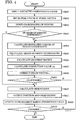
- Fig. 4 is a flowchart of a process for calculating parameters representing the position and orientation of the targeted object 13. This process is performed such that the CPU 1001 executes the program of the software corresponding to the position-orientation calculating unit 12. In a stage prior to the following processing, program code in accordance with the flowchart shown in Fig. 4 should be loaded into the RAM 1002 beforehand.
- Predicted orientation value R* is assumed to include only a drift error in the azimuth direction. Accordingly, a model is used in which the orientation of the targeted object 13 can be obtained by determining only the update value ⁇ of the azimuth-drift-error correction value.
- step S400 predicted orientation value R* (the output of the orientation predicting unit 15) of the targeted object 13 is input from the data storage unit 17 to the position-orientation calculating unit 12.
- x ⁇ -1 , y ⁇ -1 , and z ⁇ -1 represent the position of the targeted object 13 which is calculated in step S411 in the previous cycle (at time ⁇ -1).
- step S402 sets of the image coordinates of the indices detected by the index detecting unit 11 and object coordinates (coordinate values in the object coordinate system) thereof are input from the data storage unit 17 to the position-orientation calculating unit 12. For example, in the case of Fig. 1 , image coordinates u c P1 , u c P2 , and u d P2 , and object coordinates x C P1 and x C P2 corresponding thereto are input.
- step S403 the position-orientation calculating unit 12 determines whether the input index information includes information sufficient for estimating the position and orientation.
- the result of determination of the position-orientation calculating unit 12 allows the process to branch. Specifically, if the total number of physical indices whose images are input is not less than two, the position-orientation calculating unit 12 proceeds to step S404. If the total number of the indices whose images are input is less than two, the position-orientation calculating unit 12 proceeds to step S410. For example, in the case shown in Fig. 1 , the process proceeds to step S404 since two indices are detected (although the number of projected images is three, the number of physical indices is two).
- step S404 for each index P km , estimated value u Pkm* of the image coordinates thereof is calculated by the position-orientation calculating unit 12.
- the image Jacobian is, in other words, a 2-by-4 Jacobian matrix having, as elements, solutions obtained by partially differentiating function F B (represented by expression (3)) with respect to each element of state vector s.
- step S408 the position-orientation calculating unit 12 updates state vector s by using the correction value ⁇ s calculated in step S407 in accordance with the following expression: s + ⁇ s ⁇ s
- step S409 the position-orientation calculating unit 12 determines whether or not calculation converges by using a criterion such as determining whether or not error vector U is less than a predetermined threshold value, or determining whether or not correction value ⁇ s is less than a predetermined threshold value. If the calculation does not converge, the position-orientation calculating unit 12 performs step S404 and the subsequent steps again by using state vector s obtained after correction.
- a criterion such as determining whether or not error vector U is less than a predetermined threshold value, or determining whether or not correction value ⁇ s is less than a predetermined threshold value.
- the orientation R of the targeted object 13 is calculated.
- step S411 the position-orientation calculating unit 12 outputs information of the obtained position and orientation of the targeted object 13 to the exterior through the interface 1009.
- the position-orientation calculating unit 12 also outputs the position t of the targeted object 13 to the data storage unit 17.
- An output form of the position and orientation may be a set of orientation-representing 3-by-3 matrix R and position-representing three-dimensional vector t, Euler angles obtained by transforming orientation elements, a modeling transformation matrix calculated from a position and orientation, or any of other methods for describing position-and-orientation.
- step S412 by using update value ⁇ of the azimuth-drift-error correction value obtained in the above calculating steps, the position-orientation calculating unit 12 updates the azimuth-drift-error correction value ⁇ * stored in the data storage unit 17 based on the following expression: ⁇ * + ⁇ ⁇ ⁇ *
- step S413 the position-orientation calculating unit 12 determines whether or not to finish the process. If the position-orientation calculating unit 12 determines not to finish the process, it proceeds to step S400 and executes similar processing on input data in the next frame and the subsequent frames.
- the above process measures the position and orientation of the targeted object 13.
- the above illustrative example uses the plurality of bird's-eye view cameras 18a, 18b, 18c, and 18d, it is not always necessary to use the plurality of bird's-eye view cameras 18a, 18b, 18c, and 18d, and it is obvious that, even if a single bird's-eye view camera is used, advantages similar to those in the above illustrative example can be obtained. According to the above illustrative example, even if convex hulls formed by indices on images are small, the position and orientation of an object can be stably and highly accurately measured. In other words, in the case of using similarly arranged indices, a stable position and orientation can be obtained. In addition, less restriction on arrangement of indices enables measurement of many types of objects. Moreover, bird's-eye view cameras with wide view-angle for covering a broader range can be used, thus maintaining a broad measurement range for movement.
- update value ⁇ of the azimuth-drift-error correction value of the orientation sensor is found as an unknown value.
- parameters to be found by the position-orientation calculating unit 12 may be limited to the position of the targeted object 13.
- a position-and-orientation measuring apparatus according to a first modification of the first illustrative example is intended to measure the position and orientation of an arbitrary targeted object to be measured. This position-and-orientation measuring apparatus is configured by changing the function of the position-orientation calculating unit 12 in the position-and-orientation measuring apparatus according to the first illustrative example.
- the position-and-orientation measuring apparatus according to the first modification and a position-and-orientation measuring method therefor are described below.
- all update values ⁇ in the first illustrative example are set to zero.
- the position-orientation calculating unit 12 in the first modification may use those obtained by removing terms concerning update value ⁇ from the processing steps (such as the Jacobian matrices and expression (4)) of the position-orientation calculating unit 12.
- the position-and-orientation measuring apparatus According to the position-and-orientation measuring apparatus according to the first modification, the number of unknown parameters is reduced. Thus, it can be expected that the stability of obtained solutions (the position and orientation of the targeted object 13) is further improved.
- a correction-value-updating unit may be further added to the configuration shown in Fig. 1 .
- the correction-value-updating unit obtains update value ⁇ of the azimuth-drift-error correction value through an input by an operator, and updates the azimuth-drift-error correction value ⁇ * stored in the data storage unit 17 in accordance with expression (12).
- the correction-value-updating unit may use particular -keys of the keyboard 1004 as an interface.
- the correction-value-updating unit may be set so that a positive-sign '+' key is used to set an update value of +0.1 degrees and a negative sign '-' key is used to set an update value of -0.1 degrees.
- update value ⁇ of the azimuth-drift-error correction value is derived based on image information, it is obvious that a manual-input correction-value-updating unit can be jointly used.
- a position-and-orientation measuring apparatus is intended to measure the position, and orientation of an arbitrary targeted object to be measured.
- the position-and-orientation measuring apparatus according to the second modification is configured by changing the function of the position-orientation calculating unit 12 -in the position-and-orientation measuring apparatus according to the first illustrative example.
- the position-and-orientation measuring apparatus according to the second modification and a position-and-orientation measuring method therefor are described below.
- a position-orientation calculating unit in the second modification has a combination of the functions of the position-orientation calculating unit 12 in the first illustrative example and a position-orientation calculating unit in the first modification of the first illustrative example.
- the position-and-orientation measuring apparatus according to the second modification normally performs processing of the position-orientation calculating unit in the second modification which uses only a position as an unknown parameter.
- the position-and-orientation measuring apparatus according to the second modification executes processing of the position-orientation calculating unit 12 in the first illustrative example which uses the position and update value ⁇ of the azimuth-drift-error correction value as unknown parameters.
- temporal intervals for updating the azimuth-drift-error correction value be set depending on a drift characteristic of the position-orientation calculating unit 12, and it is preferable that the temporal intervals be capable of being set by an interactive operation of an operator.
- the orientation sensor 14 when an orientation sensor by which such accuracy that the azimuth drift error can be ignored is obtainable for a short time is used as the orientation sensor 14, it can be expected that the stability of the obtained solutions are improved while correcting the azimuth drift error.
- update value ⁇ of the azimuth-drift-error correction value is found based on image information at a time.
- the values of the azimuth drift error have high correlation between frames. Thus, by using information of plural frames, the values of the azimuth drift error can be found with higher accuracy.
- the position-and-orientation measuring apparatus according to the illustrative example is intended to measure the position and orientation of an arbitrary targeted object to be measured.
- the position-and-orientation measuring apparatus according to the first embodiment configured by changing the function of the position-orientation calculating unit 12 in the first illustrative example.
- the position-and-orientation measuring apparatus according to the first embodiment and a position-and-orientation measuring method therefor are described below.
- a position-orientation calculating unit 12 in the first embodiment has a combination of the functions of the position-orientation calculating unit 12 in the first illustrative example and the position-orientation calculating unit in the second modification, and executes parameter estimating processes in the first illustrative example and the second modification.
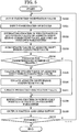
- Fig. 5 is a flowchart showing a process for calculating parameters representing the position and orientation of the targeted object 13. In a stage prior to the following steps, program code in accordance with the flowchart should be loaded into the RAM 1002 beforehand.
- step S500 similarly to step S400 in the first illustrative example predicted orientation value R* of the targeted object 13, that is, the output of the orientation predicting unit 15, is input from the data storage unit 17 to the position-orientation calculating unit 12.
- step S501 similarly to step S402, a set of the image coordinates and world coordinates of the indices detected by the index detecting unit 11 is input from the data storage unit 17 to the position-orientation calculating unit 12.
- step S503 the position-orientation calculating unit 12 sums the update value ⁇ of the azimuth-drift-error correction value calculated in step S502 to find sum ⁇ SUM .
- step S504 the position-orientation calculating unit 12 determines whether summation on a predetermined number of frames (e.g., 30 frames) has been performed. If the summation has been performed, the position-orientation calculating unit 12 proceeds to step S505. If not, the position-orientation calculating unit 12 proceeds to step S508.
- a predetermined number of frames e.g. 30 frames
- step S505 in the position-orientation calculating unit 12, by dividing the sum ⁇ SUM obtained in step S503 by the number of frames, the average of update values of the azimuth-drift-error correction value is calculated and used as new update value ⁇ of the azimuth-drift-error correction value. After that, sum ⁇ SUM is cleared to zero.
- step S506 in the position-orientation calculating unit 12, similarly to step S412 in the first illustrative example, by using the update value ⁇ of the azimuth-drift-error correction value obtained in step S505, the azimuth-drift-error correction value ⁇ * stored in the data storage unit 17 is updated based on expression (12).
- step S507 in the position-orientation calculating unit 12, by using the update value ⁇ of the azimuth-drift-error correction value obtained in step S505, the orientation of the targeted object 13 is calculated based on expression (11) and the calculated orientation is used as a new predicted orientation value.
- step S509 similarly to step S411 in the first illustrative example, the position-orientation calculating unit 12 outputs information of the position and orientation of the targeted object 13.
- step S510 the position-orientation calculating unit 12 determines whether to finish the process. If the position-orientation calculating unit 12 has determined not to finish the process, it proceeds back to step S500 and executes similar processing on data input after the next frame (time ⁇ +1).
- information of plural frames is used to realize improvement in accuracy of an update value of azimuth drift error.
- the average of update values obtained in frames is used, the median of the update values in the frames may be used, and any of other low-pass filters may be used.
- a position-and-orientation measuring apparatus measures the position and orientation of an imaging device.
- the position-and-orientation measuring apparatus according to the second illustrative example and a position-and-orientation measuring method therefor are described below.
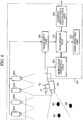
- Fig. 6 shows the configuration of the position-and-orientation measuring apparatus according to the second illustrative example.
- the position-and-orientation measuring apparatus 100 includes bird's-eye view cameras 180a, 180b, 180c, and 180d, an image input unit 160, a data storage unit 170, an index detecting unit 110, an orientation sensor 140, an orientation predicting unit 150, and a position-orientation calculating unit 120.
- the position-and-orientation measuring apparatus 100 is connected to an imaging device 130.
- the world coordinate system is defined by an origin and three perpendicularly intersecting axes in the scene.
- the object coordinate system is defined by an origin and three perpendicularly intersecting axes on the imaging device 130.
- these indices be disposed so that, when the imaging device 130 is positioned at each point in a measurement range in which a position and orientation are to be measured, the total number of subjective viewpoint indices observed in a subjective viewpoint image acquired by the imaging device 130 and the (physical) bird's-eye view indices observed in bird's-eye view images acquired by the bird's-eye view cameras 180a, 180b, 180c, and 180d is at least two. In the state shown in Fig.
- three subjective viewpoint indices Q 1 , Q 2 , and Q 3 and two bird's-eye view indices P 1 and P 2 are set, and, among the three subjective viewpoint indices Q 1 , Q 2 , and Q 3 , two subjective viewpoint indices Q 1 and Q 3 are included in a field of view of the imaging device 130.
- the bird's-eye view index P 1 is included in a field of view of the bird's-eye view camera 180c
- the bird's-eye view index P 2 is included in fields of view of the bird's-eye view cameras 180c and 180d.
- Subjective viewpoint indices Q k and bird's-eye view indices P k may be formed by, for example, spherical or circular markers having different colors, or feature points such as natural features having different texture features.
- Subjective viewpoint indices Q k and bird's-eye view indices P k may have any form if the image coordinates of projected images on a captured image can be detected and each index can be identified in some manner.
- Both subjective viewpoint indices Q k and bird's-eye view indices P k may be deliberately set or may have natural shapes which are not deliberately set.
- An image (hereinafter referred to as a "subjective viewpoint image”) output by the imaging device 130 is input to the position-and-orientation measuring apparatus 100.
- the bird's-eye view cameras 180a, 180b, 180c, and 180d are fixedly disposed at such positions that, when the imaging device 130 is positioned in the measurement range, one of the bird's-eye view cameras 180a, 180b, 180c, and 180d can capture the image of the imaging device 130.
- the position and orientation of each of the bird's-eye view cameras 180a, 180b, 180c, and 180d in the world coordinate system should be stored as known values in the data storage unit 170 beforehand.
- Images (hereinafter referred to as "bird's-eye view images”) output by the bird's-eye view cameras 180a, 180b, 180c, and 180d are input to the image input unit 160.
- the subjective viewpoint image and bird's-eye view images input to the position-and-orientation measuring apparatus 100 are converted into digital data by the image input unit 160.
- the image input unit 160 stores the digital data in the data storage unit 170.
- the orientation sensor 140 is mounted on the imaging device 130.
- the orientation sensor 140 measures its present orientation and outputs the measured orientation to the orientation predicting unit 150.
- the orientation sensor 140 is a sensor unit based on angular rate sensors such as gyroscopes, and is formed of, for example, a TISS-5-40 made by Tokimec Inc. in Japan, or an InertiaCube2 made by InterSense Inc. in the United States.
- a measured orientation value obtained by the above sensor is an orientation which differs from the actual orientation and which has an error.
- the above orientation sensor has, as components, some acceleration sensors for observing the gravitational direction of the earth, and has a function of canceling accumulation of drift error in the direction of an angle of inclination.
- the above orientation sensor has a property of producing no drift error in the direction of the angle of inclination (pitch angle and roll angle).
- the above sensor has drift error that is accumulated with the lapse of time concerning an angle around the gravitational axis, that is an azimuth (yaw) angle direction.
- the orientation predicting unit 150 receives azimuth-drift-error correction value ⁇ from the data storage unit 170, predicts the orientation of the imaging device 130 by correcting the measured orientation value input from the orientation sensor 140, and outputs the predicted orientation to the data storage unit 170.
- the subjective viewpoint image and the bird's-eye view images are input from the data storage unit 170 to the index detecting unit 110, and the image coordinates of indices photographed in the input images are detected.
- the indices are formed of markers having different colors
- regions that correspond to the markers' colors are detected from the bird's-eye view images, and their barycentric positions are used as detected coordinates of the indices.
- the positions of the indices are detected by implementing template matching based on template images for the indices which are stored beforehand as known information.
- the calculation load required for index detection can be reduced and false detection and false identification of indices can be reduced.
- the index detecting unit 110 outputs the image coordinates of the detected indices and their identifiers to the data storage unit 170.
- the indices detected in the subjective viewpoint image are represented by Q kn .
- the indices detected in the bird's-eye view images are represented by P kxm .
- the letter N represents the number of indices detected in the subjective viewpoint image
- the letter M x represents the number of indices detected in each of the bird's-eye view images.
- the letter M represents the sum of indices detected in the bird's-eye view images.
- the image coordinates of detected indices Q kn are represented by u Qkn
- the image coordinates of detected indices P kxm are represented by u a Pkam , u b Pkbm , u c Pkcm , and u d Pkdm depending on the identifiers of bird's-eye view cameras that capture the images. For example, in the case shown in Fig.
- the predicted value of the orientation of the imaging device 130, sets of the image coordinates u Qkn and world coordinates x W Qkn of the subjective viewpoint indices detected by the index detecting unit 110 and, sets of the image coordinates u Pkam , u Pkbm , u Pkcm , and u Pkdm of the bird's-eye view cameras and object coordinates (coordinate values in the object coordinate system) x C Pkam , x C Pkbm , x C Pkcm , and x C Pkdm are input from the data storage unit 170 to the position-orientation calculating unit 120.
- the position-orientation calculating unit 120 calculates the position and orientation of the imaging device 130 based on the above information and outputs the calculated position and orientation through an interface (not shown). In addition, the position-orientation calculating unit 120 outputs the calculated position to the data storage unit 170, and updates an azimuth-drift-error correction value stored in the data storage unit 170 by using an update value of the azimuth-drift-error correction value of the orientation sensor 140, which is derived in the process of calculating the position and orientation of the imaging device 130.
- the data storage unit 170 stores various types of data, such as an azimuth-drift-error correction value, images input from the image input unit 160, a predicted value of the orientation input from the orientation predicting unit 150, a calculated position value input from the position-orientation calculating unit 120, the image coordinates and identifiers of indices input from the index detecting unit 110, the world coordinates of subjective viewpoint indices, which are known values, the object coordinates (coordinate values in the object coordinate system) of bird's-eye view indices, and camera parameters of the bird's-eye view cameras 180a, 180b, 180c, and 180d.
- the various types of data are input/output from/to the data storage unit 170, if necessary.
- Each of the image input unit 160, data storage unit 170, index detecting unit 110, orientation predicting unit 150, and position-orientation calculating unit 120, shown in Fig. 6 may be treated as separate devices. Alternatively, by installing each unit as software into one or a plurality of computers, and using the CPU of each computer to execute the software, the function of the unit may be realized. In the second illustrative example, the image input unit 160, the data storage unit 170, the index detecting unit 110, the orientation predicting unit 150, and the position-orientation calculating unit 120 are treated as software to be executed by a single computer.
- the basic configuration of a computer that executes each of the image input unit 160, data storage unit 170, index detecting unit 110, orientation predicting unit 150, and position-orientation calculating unit 120 as software is shown by a block diagram in Fig. 1 .
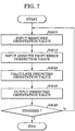
- Fig. 7 is a flowchart showing a process of the orientation predicting unit 150. This process is performed such that the CPU 1001 executes the software program of the orientation predicting unit 150. In a stage prior to implementation of the following process, program code in accordance with the flowchart should be loaded into the RAM 1002 beforehand.
- orientation is represented by 3-by-3 rotating matrix R.
- step S3000 measured orientation value R # ( # represents a sensor-measured value) is input from the orientation sensor 140 to the orientation predicting unit 150.
- step S3010 azimuth-drift-error correction value ⁇ * is input from the data storage unit 170 to the orientation predicting unit 150.
- step S3020 by subjecting measured orientation value R # (representing the orientation of the orientation sensor 140) to a transformation from the orientation of the orientation sensor 140 to that of the imaging device 130, and correcting drift error based on the azimuth-drift-error correction value ⁇ *, the orientation predicting unit 150 calculates the orientation of the imaging device 130 as a predicted orientation value R*.
- R * ⁇ R ⁇ * ⁇ R # ⁇ R SC
- step S3030 the orientation predicting unit 150 outputs predicted orientation value R* to the data storage unit 170.
- step S3040 the orientation predicting unit 150 determines whether to finish the process. If the orientation predicting unit 150 has determined not to finish the process, it proceeds back to step S3000.
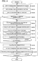
- Fig. 8 is a flowchart showing a process for calculating parameters representing the position and orientation of the imaging device 130. This process is performed such that the CPU 1001 executes the software program of the position-orientation calculating unit 120. In a stage prior to implementation of the following process, program code in accordance with the above flowchart should be loaded into the RAM 1002 beforehand.
- Predicted orientation value R* is assumed to include only a drift error in the azimuth direction. Accordingly, a model is used in which the orientation of the imaging device 130 can be obtained by determining only the update value ⁇ of the azimuth-drift-error correction value.
- step S4000 predicted orientation value R* (the output of the orientation predicting unit 150) of the imaging device 130 is input from the data storage unit 170 to the position-orientation calculating unit 120.
- x ⁇ -1 , Y ⁇ -1 , and z ⁇ -1 represent the position of the imaging device 130 which is calculated in step S4110 in the previous cycle (at time ⁇ -1 ).
- step S4020 a set of the image coordinates of the subjective viewpoint indices detected by the index detecting unit 110 and the world coordinates thereof, and sets of the image coordinates of the bird's-eye view indices detected by the index detecting unit 110 and object coordinates (coordinate values in the object coordinate system) thereof are input from the data storage unit 170 to the position-orientation calculating unit 120.
- the position-orientation calculating unit 120 For example, in the case shown in Fig.
- the image coordinates u Q1 and u Q3 of the subjective viewpoint indices and world coordinates x W Q1 and x W Q3 corresponding thereto, and the image coordinates u c P1 , u c P2 , and u d P2 and object coordinates x C P1 and x C P2 corresponding thereto are input.
- step S4030 the position-orientation calculating unit 120 determines whether the input index information includes information sufficient for estimating the position and orientation.
- the result of determination of the position-orientation calculating unit 120 allows the process to branch. Specifically, if the total number of physical indices whose images are input is not less than two, the position-orientation calculating unit 120 proceeds to step S4040. If the total number of the indices whose images are input is less than two, the position-orientation calculating unit 120 proceeds to step S4100. For example, in the case shown in Fig. 8 , two subjective viewpoint indices and two bird's-eye view indices (although the number of projected images is three, the number of physical indices is two) are detected, so that the total number is four. Accordingly, the process proceeds to step S4040.
- step S4040 based on present state vector s, the position-orientation calculating unit 120 calculates estimated value of the image coordinates of each of the subjective viewpoint indices Q kn and the bird's-eye view indices P km input in step S4020.
- u Q kn* of image coordinates of each subjective viewpoint index Q kn is calculated by using the following function of world coordinates x W Qkn for each Q kn and present state vector s:
- u Q k n * F C x W Q k n , s
- u Pkm* of image coordinates of each bird's-eye view index P km is calculated by using the following function of object coordinates (coordinate values in the object coordinate system) x C Pkm for each P km and state vector s.
- u P k m * F B x C P k m , s
- step S4060 for each of the indices (the subjective viewpoint indices and the bird's-eye view indices), the position-orientation calculating unit 120 calculates an image Jacobian concerning state vector s.
- step S4080 by using the correction value ⁇ s calculated in step S4070, the position-orientation calculating unit 120 corrects state vector s in accordance with the following expression, and uses the obtained value as a new estimated value. s + ⁇ s ⁇ s
- step S4090 the position-orientation calculating unit 120 determines whether or not calculation converges by using a criterion such as determining whether or not error vector U is less than a predetermined threshold value, or determining whether or not correction value ⁇ s is less than a predetermined threshold value. If the calculation does not converge, the position-orientation calculating unit 120 performs step S4040 and the subsequent steps again by using state vector s obtained after correction.
- a criterion such as determining whether or not error vector U is less than a predetermined threshold value, or determining whether or not correction value ⁇ s is less than a predetermined threshold value.
- step S4110 the position-orientation calculating unit 120 outputs information of the obtained position and orientation of the imaging device 130 to the exterior through the interface 1009.
- the position-orientation calculating unit 120 also outputs the position t of the imaging device 130 to the data storage unit 170.
- An output form of the position and orientation may be a set of orientation-representing 3-by-3 matrix R and position-representing three-dimensional vector t, Euler angles obtained by transforming orientation elements, a viewing transformation matrix calculated from a position and orientation, or any of other method for describing position-and-orientation.
- step S4120 by using the update value ⁇ of the azimuth-drift-error correction value obtained in the above calculating steps, the position-orientation calculating unit 120 updates the azimuth-drift-error correction value ⁇ * stored in the data storage unit 170 based on the following expression: ⁇ * + ⁇ ⁇ ⁇ *
- step S4130 the position-orientation calculating unit 120 determines whether or not to finish the process. If the position-orientation calculating unit 120 determines not to finish the process, it proceeds to step S4000 and executes similar processing on input data in the next frame and the subsequent frames.
- the above process measures the position and orientation of the imaging device 130.
- the position and orientation of the imaging device 130 can be measured. Accordingly, even if the subjective viewpoint image is obstructed (by hand or the like), the position and orientation of the imaging device 130 can be measured based on bird's-eye view image information (observation of at least two bird's-eye view indices). Conversely, even in such a situation that all bird's-eye view indices are completely obstructed, the position and orientation of the imaging device 130 can be measured based on subjective viewpoint image information (observation of at least two subjective viewpoint indices).
- the plurality of bird's-eye view cameras 180a, 180b, 180c, and 180d are used, they are not always required. Even in the case of using a single bird's-eye view camera, it is obvious that advantages similar to those in the second illustrative example can be obtained.
- the second illustrative example is intended to measure the position and orientation of an imaging device that moves in a space.
- a position-and-orientation measuring apparatus according to a first modification of the second illustrative example is intended to measure the position and orientation of an arbitrary targeted object.
- This position-and-orientation measuring apparatus is configured by adding a subjective viewpoint camera to the position-and-orientation measuring apparatus according to the second illustrative example.
- the position-and-orientation measuring apparatus according to the first modification of the second illustrative example and a method therefor are described below.
- Fig. 9 is a block diagram showing the configuration of the position-and-orientation measuring apparatus (denoted by reference numeral 500) according to the first modification of the second illustrative example.
- the position-and-orientation measuring apparatus 500 includes bird's-eye view cameras 180a, 180b, 180c, and 180d, an image input unit 160, a data storage unit .170, an index detecting unit 110, an orientation sensor 140, an orientation predicting unit 150, a position-orientation detecting unit 520, and a subjective viewpoint camera 530.
- the position-and-orientation measuring apparatus 500 differs from the second illustrative example in that an image captured by the subjective viewpoint camera 530 is input as a subjective viewpoint image to the image input unit 160, that a predicted orientation value obtained by the orientation predicting unit 150 is the orientation of the subjective viewpoint camera 530, and that the orientation sensor 140 is mounted on the subjective viewpoint camera 530.
- the subjective viewpoint camera 530 is fixedly mounted on the targeted object 580.
- the position and orientation of the targeted object 580 in a subjective viewpoint camera coordinate system should be known.
- Predicted orientation value R* of the subjective viewpoint camera 530 sets of the image coordinates and world coordinates of each subjective viewpoint index detected by the index detecting unit 110, and sets of the image coordinates of each bird's-eye view and subjective viewpoint camera coordinates corresponding thereto are input from the data storage unit 170 to the position-orientation detecting unit 520.
- the position-orientation detecting unit 520 calculates the position and orientation of the subjective viewpoint camera 530 by performing processing similar to that by the position-orientation calculating unit 120 in the second illustrative example.
- the position-orientation detecting unit 520 outputs the calculated position to the data storage unit 170, and updates an azimuth-drift-error correction value stored in the data storage unit 170 by using update value ⁇ of an azimuth-drift-error correction value of the orientation sensor 140 which is derived from the process of calculating the position and orientation.
- the position-orientation detecting unit 520 calculates the position and orientation of the targeted object 580.
- the calculated position and orientation are output to the exterior through the interface 1009.
- the above manner realizes measurement of the position and orientation of the arbitrary targeted object.
- the position-orientation detecting unit 520 finds the position and orientation of the targeted object 580.
- the position-orientation detecting unit 520 may directly find the position and orientation of the targeted object 580.
- the orientation predicting unit 150 is configured to estimate the position and orientation of the targeted object 580 (R SC in expression (14) is set to be a 3-by-3 matrix for transforming the orientation from the coordinate system of the targeted object to the sensor coordinate system).
- R CO represents a matrix for transforming the orientation from a targeted object coordinate system (coordinate system in which a point on the targeted object
- the targeted object 580 may be an imaging device for capturing images of a scene.
- the subjective viewpoint camera 530 may be, for example, upwardly disposed so as to have a field of view different from that of the imaging device for capturing the images of the scene, and subjective viewpoint index Q k may be accordingly disposed in the field of view of the subjective viewpoint camera 530, e.g. on the ceiling. This contributes to lessen a problem of image deformation, etc., since subjective viewpoint index Q k is not included in the field of view of the imaging device for capturing the images of the scene.
- the measurement of the position and orientation of the targeted object 580 may be realized with high accuracy in both position and orientation.
- each of the position-orientation calculating unit 120 and the position-orientation detecting unit 520 in each of the position-orientation calculating unit 120 and the position-orientation detecting unit 520, four-value state vector s representing an update value of the azimuth-drift-error correction value and a position is used as an unknown value, and such state vector s that minimizes the sum of errors between detected coordinates (actually measured values) and calculated values of the subjective viewpoint index and bird's-eye view index is found.
- a geometric index restraining condition is used.
- a position-and-orientation measuring apparatus according to the second modification of the second illustrative example is characterized in that a position-orientation detecting unit using a technique different from an entire error minimizing technique is included as a component.
- the position-and-orientation measuring apparatus is basically similar in configuration to that according to the second illustrative example. However, in this second modification, the position-orientation calculating unit 120 in the second illustrative example is replaced by a position-orientation calculating unit 120' (not shown) different therefrom. In other words, a process of the position-orientation calculating unit 120' differs from that of the position-orientation calculating unit 120 in the second illustrative example.
- the position-and-orientation measuring apparatus according to the second modification of the second illustrative example and a position-and-orientation measuring method therefor are described below.
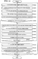
- Fig. 10 is a flowchart showing a process which calculates parameters representing the position and orientation of the imaging device 130 and which is executed such that the CPU 1001 executes the software program of the position-orientation calculating unit 120'.
- program code in accordance with the above flowchart should be loaded into the RAM 1002 beforehand.
- step S6000 predicted orientation value R* (the output of the orientation predicting unit 150) of the orientation of the imaging device 130 is input from the data storage unit 170 to the position-orientation calculating unit 120'.
- step S6003 a set of the image coordinates and camera coordinates of a bird's-eye view index detected by the index detecting unit 110 is input to the position-orientation calculating unit 120'.
- step S6006 based on image coordinates u P , the position-orientation calculating unit 120' calculates a parameter representing a straight line restraining the position of bird's-eye view index P in the world coordinate system.
- R WB represents a 3-by-3 matrix representing an orientation in the world coordinate system of the bird's-eye view cameras 180a, 180b, 180c, and 180d, which detect bird's-eye view index P
- f B x and f B y respectively represent focal distances in the X axis and Y axis directions, and are stored as known values in the external storage device 1007 beforehand.
- the straight line represented by expression (36) passes through the position in the world coordinate system of one of the bird's-eye view cameras 180a, 180b, 180c, and 180d, and the position of the bird's-eye view index P, and the position of the bird's-eye view index P is obtained such that parameter ⁇ takes an appropriate value.
- a total of two parameters that is, parameter ⁇ setting the position of the bird's-eye view index P in the world coordinate system and update value ⁇ of the azimuth-drift-error correction value of the orientation sensor 140, are hereinafter treated as unknown parameters to be calculated.
- ⁇ that represents a position on line l W closest to world coordinates of bird's-eye view index P which are obtained from the position of the imaging device 130 obtained in previous processing is set as ⁇ -1 .
- step S6020 a set of the image coordinates and world coordinates of each subjective viewpoint index detected in the index detecting unit 110 is input to the position-orientation calculating unit 120'.
- step S6030 the position-orientation calculating unit 120' determines whether or not the number N of the input subjective viewpoint indices is at least one. If the number N of the input subjective viewpoint indices is less than one, the process proceeds to steps S6100 without performing updating of s' implemented in steps S6040 to S6090.
- an estimated image-coordinate value of each subjective viewpoint index is found in accordance with a relationship in position and orientation between the imaging device 130 and the subjective viewpoint index.
- step S6050 for the subjective viewpoint index Q kn , the position-orientation calculating unit 120' calculates error ⁇ u Qkn between estimated value u Qkn* and actually measured value u Qkn of the image coordinate on the basis of expression (23).
- step S6070 the position-orientation calculating unit 120' calculates correction value ⁇ s' of state vector s' by using expression (27) (s is replaced by s').
- U represents a 2N-dimensional error vector in which errors ⁇ u Qkn are vertically arranged for each subjective viewpoint index
- ⁇ represents a 2N-by-2 matrix in which image Jacobians J us' Qkn obtained for the subjective viewpoint index are vertically arranged.
- step S6080 by using the correction value ⁇ s' calculated in step S6070, the position-orientation calculating unit 120' corrects state vector s' based on expression (30) (s is replaced by s') and uses the obtained value as a new estimated value.
- step S6090 the position-orientation calculating unit 120' determines whether or not calculation converges by using a criterion such as determining whether or not error vector U is less than a predetermined threshold value, or determining whether or not correction value ⁇ s' is less than a predetermined threshold value. If the calculation does not converge, the position-orientation calculating unit 120' performs step S6040 and the subsequent steps again by using state vector s' obtained after correction.
- a criterion such as determining whether or not error vector U is less than a predetermined threshold value, or determining whether or not correction value ⁇ s' is less than a predetermined threshold value. If the calculation does not converge, the position-orientation calculating unit 120' performs step S6040 and the subsequent steps again by using state vector s' obtained after correction.
- step S6100 the position-orientation calculating unit 120' calculates the orientation of the imaging device 130 from the obtained state vector s'.
- Calculation of orientation R is performed by using the update value ⁇ of the azimuth-drift-error correction value which is obtained up to the previous step on the basis of expression (31).
- step S6110 the position-orientation calculating unit 120' outputs information of the position and orientation of the imaging device 130 to the exterior through the interface 1009.
- the position-orientation calculating unit 120' also outputs the position t of the imaging device 130 to the data storage unit 170.
- An output form of the position and orientation may be a set of orientation-representing 3-by-3 matrix R and position-representing three-dimensional vector t, Euler angles obtained by transforming orientation elements, a viewing transformation matrix calculated from a position and orientation, or any of other position-and-orientation describing methods.
- step S6120 by using the update value ⁇ of the azimuth-drift-error correction value obtained in the above calculating steps, the position-orientation calculating unit 120' updates the azimuth-drift-error correction value ⁇ * stored in the data storage unit 170 based on the expression (32) .
- step S6130 the position-orientation calculating unit 120' determines whether or not to finish the process. If the position-orientation calculating unit 120' determines not to finish the process, it proceeds to step S6000 and executes similar processing on input data in the next frame and the subsequent frames.
- a straight line on which a bird's-eye view index obtained from the bird's-eye view cameras 180a, 180b, 180c, and 180d exists is used as a restraint condition, and under this restraint condition, such position and orientation of the imaging device 130 as to minimize error in subjective viewpoint index on a subjective viewpoint image can be obtained.
- the result of measurement of the position and orientation in the second modification of the second illustrative example more preferentially relies on information obtained from the bird's-eye view cameras 180a, 180b, 180c, and 180d compared with the result of measurement of the position and orientation in the second illustrative example. Accordingly, in a situation in which the reliability of information obtained from the bird's-eye view cameras 180a, 180b, 180c, and 180d is relatively higher than that obtained from the imaging device 130, for example, when a high resolution bird's-eye view camera is available, and when only a marker having very high detection accuracy is available, the position-and-orientation measuring apparatus according to the second modification of the second illustrative example functions more effectively compared with the second illustrative example
- each of the position-orientation calculating units 120, 520, and 120' finds an update value, which is an unknown value, of the azimuth-drift-error correction value of the orientation sensor 140.
- correction values of error in the three axis directions of the orientation sensor 140 can be found without limiting correcting items of orientation to only azimuth directions.
- a position-and-orientation measuring apparatus according to the third modification of the second illustrative example is almost identical in configuration to that according to the second illustrative example Accordingly, portions different from those in the second illustrative example are described below.
- the data storage unit 170 stores rotation-error correction matrix ⁇ R* of the orientation sensor 140 instead of azimuth-drift-error correction value ⁇ * of the orientation sensor 140.
- rotation-error correction matrix ⁇ R* of the orientation sensor 140 is input to the orientation predicting unit 150 (step S3010).
- x -1 , y -1 , and z -1 represents the position of the imaging device 130 which is calculated in the previous processing
- ⁇ *, ⁇ *, and ⁇ * represent three-valued representation obtained from predicted orientation value R*.
- the position-orientation calculating unit 120 sets branching based on the number of input indices (step S4030) by determining whether or not a total number of the input indices is at least three.
- the position-orientation calculating unit 120 uses the obtained state vector s" to calculate orientation R of the imaging device 130 on the basis of expression (40).
- step S4120 the position-orientation calculating unit 120 uses the orientation R of the imaging device 130 obtained in the above calculating step to calculate rotation-error correction matrix ⁇ R* of the orientation sensor 140 on the basis of the following expression: R ⁇ R * ⁇ 1 ⁇ ⁇ R * ⁇ ⁇ R * and updates a value stored in the data storage unit 170.
- the above processing measures the position and orientation of the imaging device 130.
- a position-and-orientation measuring apparatus according to the fourth modification of the second illustrative example is characterized in having a configuration in which upper view cameras 180 (different from the imaging device 130) fixed to the imaging device 130 capture images of upper view indices P k disposed in the world coordinate system, instead of using bird's-eye view cameras.
- the position-and-orientation measuring apparatus according to the fourth modification of the second illustrative example and a position-and-orientation measuring method therefor are described below.
- Fig. 11 shows the configuration of the position-and-orientation measuring apparatus according to the fourth modification of the second illustrative example.
- the position-and-orientation measuring apparatus (denoted by reference numeral 700) according to the fourth modification of the second illustrative example includes upper view cameras 180a and 180b, an image input unit 160, a data storage unit 770, an index detecting unit 110, an orientation sensor 140, an orientation predicting unit 150, and a position-orientation calculating unit 720.
- the position-and-orientation measuring apparatus 700 is connected to the imaging device 130.
- Portions having functions identical to those in the second illustrative example are denoted by reference numerals identical to those shown in Fig. 6 . Accordingly, a description of the portions is omitted.
- the upper view cameras 180a and 180b whose positions and orientations in the subjective viewpoint camera coordinate system are known, are fixedly disposed on the imaging device 130.
- a term "upper view camera” to indicate the camera that is placed on the imaging device 130 and has a field-of-view which is different from that of the imaging device 130; the direction of the camera is not limited to the "upper" direction.
- three subjective viewpoint indices Q 1 , Q 2 , and Q 3 and two upper view indices P 1 and P 2 are set, and, among them, two subjective viewpoint indices Q 1 and Q 3 are included in a field of view of the imaging device 130, upper view index P 1 is included fields of view of the upper view cameras 180a and 180b, and upper view index P 2 is included in the field of view of the upper view camera 180b.
- the upper view cameras 180a and 180b are disposed so that, when the imaging device 130 is positioned in a measurement range, either of the upper view cameras 180a and 180b can capture images of upper view indices P k .
- the positions and orientations of the upper view cameras 180a and 180b should be stored as known values in the data storage unit 770 beforehand.
- a predicted value of the orientation of the imaging device 130, a set of image coordinate u Qkn and world coordinate x W Qkn of each subjective viewpoint index detected by the index detecting unit 110, and sets of image coordinates u Pkm of each upper view index and world coordinates x W Pkm corresponding thereto are input from the data storage unit 770 to the position-orientation calculating unit 720.
- the position-orientation calculating unit 720 calculates the position and orientation of the imaging device 130 and outputs the calculated position and orientation to the exterior through an interface (not shown).
- the position-orientation calculating unit 720 outputs the calculated position of the imaging device 130 to the data storage unit 770. Moreover, the position-orientation calculating unit 720 updates an azimuth-drift-error correction value stored in the data storage unit 770 by using an updated azimuth-drift-error correction value of the orientation sensor 140, which is derived in the process of calculating the position and orientation.
- the data storage unit 770 stores various types of data, such as an azimuth-drift-error correction value, images input from the image input unit 160, a predicted value of the orientation input from the orientation predicting unit 150, a calculated position value input from the position-orientation calculating unit 150, the image coordinates and identifiers of indices input from the index detecting unit 110, the world coordinates of subjective viewpoint indices, which are known values, the world coordinates of upper view indices, and the positions and orientations of the upper view cameras 180a and 180b in the subjective viewpoint camera coordinate system.
- the various types of data are input/output from/to the data storage unit 770, if necessary.
- the flowchart of a process for calculating parameters representing the position and orientation of the imaging device 130 in the fourth modification of the second illustrative example is almost identical to the flowchart ( Fig. 8 ) in the second illustrative example. In the following, only portions different from those in the second illustrative example are described.
- step S4020 instead of image coordinates and subjective viewpoint camera coordinates (coordinate values in the subjective viewpoint camera coordinate system) of the bird's-eye view indices, image coordinates and world coordinates of the upper view indices are input to the position-orientation calculating unit 720.
- step S4040 calculation of estimated image coordinate value u Pkm* of each upper view index P km is performed by using the following function of world coordinate x W Pkm of the upper view index P km and the present state vector s:
- u P k m * F D x W P k m , s
- the fourth modification of the second illustrative example uses the plurality of upper view cameras 180a and 180b, it is not always necessary to use the plurality of upper view cameras 180a and 180b, and it is obvious that, even if a single upper view camera is used, advantages similar to those in the fourth modification of the second illustrative example be obtained.
- the configuration described in the fourth modification of the second illustrative example is applicable, in which the upper view cameras 180a and 180b fixed to the imaging device 130 can capture images of upper view indices P k disposed in the world coordinate system.
- Gauss-Newton method which is represented by expression (9) or (27), for calculating ⁇ s based on error vector U and matrix ⁇
- the calculation of correction value ⁇ s does not always need to be performed by using the Gauss-Newton method.
- the calculation may be performed by using the Levenberg-Marquardt (LM) method, which is a known iterative method to solve a nonlinear equation.
- LM Levenberg-Marquardt
- M estimation that is a known robust estimation technique, may be combined and any of other numerical calculating techniques may be applied.
- each of the above embodiments and illustrative examples and its modifications uses, for each input image, a nonlinear optimization technique for finding the optimal solution (which minimizes error).
- a technique which, based on an error in index on the image, eliminates the error is not limited to the nonlinear optimization technique.
- an extended Kalman filter and an iterative extended Kalman filter which are known as techniques that, based on an error in index on an image, find a solution eliminating the error, and which are described in detail in J. Park, B. Jiang, and U. Neumann, "Vision-based pose computation: robust and accurate augmented reality tracking", Proc. Second International Workshop on Augmented Reality (IWAR'99), pp.
- indices that each index indicates a set of coordinates are used.
- the indices are not limited to index types. Other types of indices may be used.
- each of the above embodiments illustrative examples and their modifications may use, as a subjective viewpoint index and/or bird's-eye view index, such a specific geometric shape marker as used in a known position-and-orientation measuring apparatus (see, for example, Takahashi, Ishii, Makino, Nakashizu, "VR Intafesu-notameno Tangan-niyoru Chohokei Maka Ichi-shisei-no Koseido Jitsujikan Suiteiho (Method for Real-Time Estimation of the Position And Orientation of Rectangular Marker through Single View for VR interface)", Sanjigen Konfarensu 96 Koen Ronbunshu (Three-dimensional Conference '96 Collected Papers), pp.
- a quadrangle marker when used as an index, by storing the world coordinates of the vertices of the quadrangle as known values, or calculating these values from the position, orientation, and size of the marker, and detecting the image coordinates of the vertices from an image, an advantage can be obtained which is similar to that obtained in the case of using four markers in the first illustrative example, first embodiment and their modifications.
- a configuration having one quadrangle marker (having ID information) on a targeted object to be measured, or a configuration having one quadrangle marker mounted on an orientation sensor is a particularly suitable form because it is expected that the configuration has good accuracy and identification of marker detection from the image.
- quadrangle marker see, for example, Kato, M. BillingHurst, Asano, Tachibana, "Maka Tsuisekinimotozuku Kakuchogenjitsukan Shisutemu-to Sono Kyariburehshon (Augmented Reality System based on Marker Tracking and Calibration Thereof)", Nippon Bacharu Riarithi Gakkai Ronbunshi (The Virtual Reality Society of Japan, Collected Papers), vol. 4, no. 4, pp. 607-616, 1999 .
- line index a line feature index
- another known position-and-orientation measuring apparatus see, for example, D. G. Lowe “Fitting parameterized three-dimensional models to images", IEEE Transactions on PAMI, vol. 13, no. 5, pp. 441-450, 1991 ).
- indices as subjective viewpoint indices and bird's-eye view indices.
- One of the preferred examples is using natural line indices as subjective viewpoint indices and colored spherical markers as bird's-eye view indices.
- the number of subjective viewpoint cameras 530 is one.
- a plurality of subjective viewpoint cameras may be mounted on the targeted object 580 for position and orientation measurement.
- the orientation predicting unit 150 and the index detecting unit 110 process an image input from each camera.
- the orientation predicting unit 150 and the position-orientation detecting unit 520 perform arithmetic operations by using the position and orientation of the targeted object 580 as references.
- the position-orientation detecting unit 520 uses a mechanism similar to that in each illustrative example to estimate a position and orientation by forming state vector s based on the position of the targeted object 580 and the azimuth-drift-error correction value, finding an error of each index and image Jacobian from index information obtained from each image on the basis of expression (33) (R CO and t CO differ for each camera), and accumulating the obtained values to form error vector U and matrix ⁇ .
- the number of imaging devices 130 is one.
- one imaging device e.g., an imaging device for the left eye
- position and orientation measurement can be performed.
- orientation sensor having an azimuth drift error
- another type of orientation sensor having a significant error only in the azimuth direction may be used as the orientation sensor.
- the position and orientation of a targeted object can be measured by processing similar to that in the above embodiments and illustrative examples and their modifications, with the position and update value of the azimuth-drift-error correction value used as unknown parameters.
- the error property differs from the property of the azimuth drift error
- this case may not be proper for use in a form such as the first embodiment or fourth modification of the first illustrative example.
- this orientation sensor be a three-axis orientation sensor in which a measured value in the azimuth direction is always zero, the position and orientation of a targeted object can be measured by similar processing.
- a camera for image capturing through radiation having wavelengths different from those of visible radiation can be used as each bird's-eye view camera used in each of the above embodiment and illustrative examples and their modifications.
- a camera for image capturing through infrared radiation may be used as each bird's-eye view camera, and an index that emits or reflects infrared radiation may be used each bird's-eye view index.
- This case has an advantage in the second illustrative example in that, since an image of a subjective viewpoint index is not captured by the bird's-eye view camera, false detection of the subjective viewpoint index on the bird's-eye view image is eliminated.
- the index can be identified.
- the barycentric position of the region may be used as detected coordinates of an index which emits infrared radiation with timing identical to that for image capturing by the bird's-eye view camera.
- the number of bird's-eye view indices is one, control of emission timing is not required.
- cameras for image capturing through infrared radiation may be used as the subjective viewpoint camera and the bird's-eye view camera, and indices 'that that emit or reflect infrared radiation may be used both as the subjective viewpoint index and as the bird's-eye view indices.
- the camera for image capturing through radiation having wavelengths different from those of visible radiation are not limited to the camera for image capturing through infrared radiation, but a camera for image capturing through ultraviolet radiation, or the like, may be used. Moreover, a camera for simultaneous image capturing both through radiation having wavelengths different from those of visible radiation and through visible radiation may be used.
- the present invention is realized such that a storage medium (or recording medium) containing the program code of software realizing the functions of the above-described embodiment is provided to a system or an apparatus, and a computer (or CPU/MPU) of the system or apparatus reads and executes the program code in the storage medium.
- a computer or CPU/MPU
- the program code itself read from the storage medium realizes the functions of the above-described embodiment.
- the storage medium containing the program code is included in the present invention.
- the present invention includes a case in which the computer executes the read program code, whereby, in addition to realization of the functions of the above-described embodiment, the program code instructs an operating system, or the like, running on the computer to perform all or part of actual processing, an the processing implements the functions of the above-described embodiment.
- the present invention includes a case in which, after the program code read from the storage medium is written in a memory provided in an add-in card loaded into the computer or in an add-in unit connected to the computer, the program code instructs a CPU provided in the add-in card or add-in unit to perform all or part of actual processing, and the processing implements the functions of the above-described embodiment.
Claims (5)
- Procédé de traitement d'informations destiné à calculer la position et l'orientation d'un objet, le procédé de traitement d'informations comprenant les étapes consistant à :fournir en entrée une pluralité d'images capturées d'un dispositif de formation d'image pour capturer l'image de l'objet à partir d'une position de vue à vol d'oiseau ;fournir en entrée une valeur d'orientation mesurée d'un capteur d'orientation pour mesurer des informations concernant l'orientation de l'objet ;à partir de chacune des images capturées, détecter des valeurs caractéristiques concernant les coordonnées d'image d'indices disposés sur l'objet ;trouver un paramètre (S502), pour chaque image capturée, concernant l'azimut de l'objet et un paramètre concernant la position de l'objet, en utilisant les valeurs caractéristiques détectées concernant les coordonnées d'image des indices ;trouver un paramètre moyen concernant l'azimut (S503, S505) en calculant la moyenne sur un nombre prédéterminé d'images capturées du paramètre concernant l'azimut ; etcalculer la position (S508) et l'orientation (S507) de l'objet en utilisant le paramètre moyen.
- Procédé de traitement d'informations selon la revendication 1, dans lequel le paramètre concernant l'azimut de l'objet concerne une valeur de correction de l'erreur de dérive en azimut du capteur d'orientation.
- Procédé de traitement d'informations selon la revendication 1, dans lequel les indices sont donnés à partir d'un marqueur polygonal.
- Programme qui, lorsqu'il est exécuté sur un appareil de traitement d'informations, amène l'appareil de traitement d'informations à mettre en oeuvre un procédé selon l'une quelconque des revendications 1 à 3.
- Appareil de traitement d'informations destiné à calculer la position et l'orientation d'un objet, l'appareil de traitement d'informations comprenant :une unité d'entrée d'images capturées configuré pour fournir en entrée une pluralité d'images capturées d'un dispositif de formation d'image pour capturer une image de l'objet à partir d'une position de vue à vol d'oiseau par rapport à l'objet ;une unité d'entrée de valeur d'orientation mesurée configurée pour fournir en entrée une valeur d'orientation mesurée d'un capteur d'orientation pour mesurer des informations concernant l'orientation de l'objet ;une unité de détection configurée pour détecter, à partir de chacune des images capturées, des valeurs caractéristiques concernant les coordonnées d'image d'indices disposés sur l'objet ; etune unité de calcul de position et d'orientation configurée pour :trouver un paramètre, pour chaque image capturée, concernant l'azimut de l'objet et un paramètre concernant la position de l'objet, en utilisant les valeurs caractéristiques détectées concernant les coordonnées d'image des indices ;trouver un paramètre moyen concernant l'azimut en calculant la moyenne sur un nombre prédéterminé d'images capturées des paramètres concernant l'azimut ; etcalculer la position et l'orientation de l'objet en utilisant les paramètres obtenus.
Applications Claiming Priority (6)
| Application Number | Priority Date | Filing Date | Title |
|---|---|---|---|
| JP2004144893 | 2004-05-14 | ||
| JP2004144894 | 2004-05-14 | ||
| JP2004144894A JP4612804B2 (ja) | 2004-05-14 | 2004-05-14 | 位置姿勢計測方法および情報処理装置 |
| JP2004144893 | 2004-05-14 | ||
| JP2005053441A JP4566786B2 (ja) | 2004-05-14 | 2005-02-28 | 位置姿勢計測方法および情報処理装置 |
| JP2005053441 | 2005-02-28 |
Publications (3)
| Publication Number | Publication Date |
|---|---|
| EP1596332A2 EP1596332A2 (fr) | 2005-11-16 |
| EP1596332A3 EP1596332A3 (fr) | 2006-10-11 |
| EP1596332B1 true EP1596332B1 (fr) | 2018-01-24 |
Family
ID=34941306
Family Applications (1)
| Application Number | Title | Priority Date | Filing Date |
|---|---|---|---|
| EP05252971.6A Expired - Fee Related EP1596332B1 (fr) | 2004-05-14 | 2005-05-13 | Méthode et appareil de traitement d'information pour trouver la position et l'orientation d'un objet visé |
Country Status (2)
| Country | Link |
|---|---|
| US (1) | US7467061B2 (fr) |
| EP (1) | EP1596332B1 (fr) |
Families Citing this family (36)
| Publication number | Priority date | Publication date | Assignee | Title |
|---|---|---|---|---|
| US8947347B2 (en) * | 2003-08-27 | 2015-02-03 | Sony Computer Entertainment Inc. | Controlling actions in a video game unit |
| US8797260B2 (en) | 2002-07-27 | 2014-08-05 | Sony Computer Entertainment Inc. | Inertially trackable hand-held controller |
| US10086282B2 (en) | 2002-07-27 | 2018-10-02 | Sony Interactive Entertainment Inc. | Tracking device for use in obtaining information for controlling game program execution |
| EP1739622B1 (fr) * | 2005-06-28 | 2013-08-14 | Canon Kabushiki Kaisha | Identification d'un élément d'image avec deux caméras |
| US20080317313A1 (en) * | 2005-09-30 | 2008-12-25 | Ut-Battelle, Llc | System and method for tracking motion for generating motion corrected tomographic images |
| EP1946243A2 (fr) * | 2005-10-04 | 2008-07-23 | Intersense, Inc. | Tracage d'objets a l'aide de marqueurs |
| JP4739004B2 (ja) * | 2005-12-15 | 2011-08-03 | キヤノン株式会社 | 情報処理装置及び情報処理方法 |
| JP4916167B2 (ja) * | 2005-12-15 | 2012-04-11 | キヤノン株式会社 | 指標識別方法及び指標識別装置 |
| FR2896896B1 (fr) * | 2006-02-02 | 2009-09-25 | Commissariat Energie Atomique | Procede de classification d'evenements ou d'etats en deux etapes |
| DE102006035292B4 (de) * | 2006-07-26 | 2010-08-19 | Deutsches Zentrum für Luft- und Raumfahrt e.V. | Verfahren und System zum Übertragen von positionszugeordneten Informationen aus einer virtuellen in eine tatsächliche Realität und zum Anzeigen dieser Informationen in der tatsächlichen Realität sowie Verwendung eines solchen Systems |
| JP5403861B2 (ja) * | 2006-11-06 | 2014-01-29 | キヤノン株式会社 | 情報処理装置、情報処理方法 |
| US8655614B2 (en) * | 2007-11-30 | 2014-02-18 | The Boeing Company | Position only fit, POF, algorithm for blur spot target tracking and discrimination |
| JP5156571B2 (ja) * | 2008-10-10 | 2013-03-06 | キヤノン株式会社 | 画像処理装置、画像処理方法 |
| US9024972B1 (en) | 2009-04-01 | 2015-05-05 | Microsoft Technology Licensing, Llc | Augmented reality computing with inertial sensors |
| RU2009113008A (ru) * | 2009-04-08 | 2010-10-20 | Михаил Юрьевич Воробьев (RU) | Способ определения позиции и ориентации прицепа транспортного средства и устройство для его осуществления |
| JP2011203823A (ja) | 2010-03-24 | 2011-10-13 | Sony Corp | 画像処理装置、画像処理方法及びプログラム |
| JP5570316B2 (ja) * | 2010-06-17 | 2014-08-13 | キヤノン株式会社 | 撮像装置、その制御方法及びプログラム |
| US8619124B2 (en) * | 2010-10-14 | 2013-12-31 | Industrial Technology Research Institute | Video data processing systems and methods |
| JP5830662B2 (ja) * | 2010-12-09 | 2015-12-09 | パナソニックIpマネジメント株式会社 | 撮像装置 |
| US8948446B2 (en) * | 2011-01-19 | 2015-02-03 | Honeywell International Inc. | Vision based zero velocity and zero attitude rate update |
| US8863398B2 (en) * | 2011-04-01 | 2014-10-21 | Lockheed Martin Corporation | Feature-based coordinate reference |
| CN102589451A (zh) * | 2012-03-06 | 2012-07-18 | 深圳市华测检测技术股份有限公司 | 玩具弹性系绳的长度测量装置 |
| CN102589450A (zh) * | 2012-03-06 | 2012-07-18 | 深圳市华测检测技术股份有限公司 | 玩具弹性系绳长度自动测量装置 |
| US10368662B2 (en) | 2013-05-05 | 2019-08-06 | Trax Technology Solutions Pte Ltd. | System and method of monitoring retail units |
| JP6285146B2 (ja) * | 2013-10-29 | 2018-02-28 | 株式会社ミツトヨ | アーム型三次元測定機及びアーム型三次元測定機を支持する基部の傾斜補正方法 |
| US20150187101A1 (en) * | 2013-12-30 | 2015-07-02 | Trax Technology Solutions Pte Ltd. | Device and method with orientation indication |
| US20150193909A1 (en) | 2014-01-09 | 2015-07-09 | Trax Technology Solutions Pte Ltd. | Method and device for panoramic image processing |
| US10387996B2 (en) | 2014-02-02 | 2019-08-20 | Trax Technology Solutions Pte Ltd. | System and method for panoramic image processing |
| US10402777B2 (en) | 2014-06-18 | 2019-09-03 | Trax Technology Solutions Pte Ltd. | Method and a system for object recognition |
| US9964765B2 (en) * | 2015-09-11 | 2018-05-08 | The Boeing Company | Virtual display of the real-time position of a robotic device to a human operator positioned on an opposing side of an object |
| JP6702543B2 (ja) * | 2016-05-31 | 2020-06-03 | 株式会社東芝 | 情報処理装置、方法およびプログラム |
| US10146334B2 (en) | 2016-06-09 | 2018-12-04 | Microsoft Technology Licensing, Llc | Passive optical and inertial tracking in slim form-factor |
| US10146335B2 (en) | 2016-06-09 | 2018-12-04 | Microsoft Technology Licensing, Llc | Modular extension of inertial controller for six DOF mixed reality input |
| US11164332B2 (en) * | 2017-08-25 | 2021-11-02 | Chris Hsinlai Liu | Stereo machine vision system and method for identifying locations of natural target elements |
| US10555781B2 (en) * | 2017-11-15 | 2020-02-11 | Stryker Corporation | High bandwidth and low latency hybrid communication techniques for a navigation system |
| CN109143214B (zh) * | 2018-07-26 | 2021-01-08 | 上海乐相科技有限公司 | 一种采用激光扫描的目标定位方法及装置 |
Family Cites Families (2)
| Publication number | Priority date | Publication date | Assignee | Title |
|---|---|---|---|---|
| US6968282B1 (en) * | 2000-05-22 | 2005-11-22 | Snap-On Incorporated | Self-calibrating, multi-camera machine vision measuring system |
| JP4136859B2 (ja) * | 2003-01-10 | 2008-08-20 | キヤノン株式会社 | 位置姿勢計測方法 |
-
2005
- 2005-05-11 US US11/126,437 patent/US7467061B2/en not_active Expired - Fee Related
- 2005-05-13 EP EP05252971.6A patent/EP1596332B1/fr not_active Expired - Fee Related
Non-Patent Citations (1)
| Title |
|---|
| None * |
Also Published As
| Publication number | Publication date |
|---|---|
| EP1596332A3 (fr) | 2006-10-11 |
| EP1596332A2 (fr) | 2005-11-16 |
| US7467061B2 (en) | 2008-12-16 |
| US20050256391A1 (en) | 2005-11-17 |
Similar Documents
| Publication | Publication Date | Title |
|---|---|---|
| EP1596332B1 (fr) | Méthode et appareil de traitement d'information pour trouver la position et l'orientation d'un objet visé | |
| JP4593968B2 (ja) | 位置姿勢計測方法および装置 | |
| US7630555B2 (en) | Position and orientation measuring method and apparatus | |
| EP1852821B1 (fr) | Procédé et dispositif de mesure de la position et de l'orientation d'un objet | |
| CN100410622C (zh) | 用于获得目标物体的位置和方位的信息处理方法和设备 | |
| US7613361B2 (en) | Information processing method and device | |
| EP1596330B1 (fr) | Estimation de position et d'orientation de marqueurs dans des images numériques | |
| JP4136859B2 (ja) | 位置姿勢計測方法 | |
| US7489806B2 (en) | Motion detection apparatus | |
| US9355453B2 (en) | Three-dimensional measurement apparatus, model generation apparatus, processing method thereof, and non-transitory computer-readable storage medium | |
| JP5036260B2 (ja) | 位置姿勢算出方法及び装置 | |
| JP4914039B2 (ja) | 情報処理方法および装置 | |
| US20090262113A1 (en) | Image processing apparatus and image processing method | |
| JP7238060B2 (ja) | 情報処理装置及びその制御方法、並びに、プログラム | |
| CN115371665B (zh) | 一种基于深度相机和惯性融合的移动机器人定位方法 | |
| JP4566786B2 (ja) | 位置姿勢計測方法および情報処理装置 | |
| JP4726191B2 (ja) | 位置姿勢補正装置、位置姿勢補正方法、そのプログラムおよび記憶媒体 | |
| CN113474819A (zh) | 信息处理装置、信息处理方法和程序 | |
| Satoh et al. | Robot vision-based registration utilizing bird's-eye view with user's view | |
| JP5726024B2 (ja) | 情報処理方法および装置 | |
| JP4612804B2 (ja) | 位置姿勢計測方法および情報処理装置 | |
| KR102456872B1 (ko) | 영상센서와 관성센서의 강결합 융합을 이용한 손동작 추적시스템 및 방법 | |
| JP2007040980A (ja) | 情報処理方法および装置 |
Legal Events
| Date | Code | Title | Description |
|---|---|---|---|
| PUAI | Public reference made under article 153(3) epc to a published international application that has entered the european phase |
Free format text: ORIGINAL CODE: 0009012 |
|
| AK | Designated contracting states |
Kind code of ref document: A2 Designated state(s): AT BE BG CH CY CZ DE DK EE ES FI FR GB GR HU IE IS IT LI LT LU MC NL PL PT RO SE SI SK TR |
|
| AX | Request for extension of the european patent |
Extension state: AL BA HR LV MK YU |
|
| PUAL | Search report despatched |
Free format text: ORIGINAL CODE: 0009013 |
|
| AK | Designated contracting states |
Kind code of ref document: A3 Designated state(s): AT BE BG CH CY CZ DE DK EE ES FI FR GB GR HU IE IS IT LI LT LU MC NL PL PT RO SE SI SK TR |
|
| AX | Request for extension of the european patent |
Extension state: AL BA HR LV MK YU |
|
| 17P | Request for examination filed |
Effective date: 20070411 |
|
| AKX | Designation fees paid |
Designated state(s): DE FR GB IT NL |
|
| 17Q | First examination report despatched |
Effective date: 20070814 |
|
| REG | Reference to a national code |
Ref country code: DE Ref legal event code: R079 Ref document number: 602005053422 Country of ref document: DE Free format text: PREVIOUS MAIN CLASS: G06T0007000000 Ipc: G06T0007330000 |
|
| GRAP | Despatch of communication of intention to grant a patent |
Free format text: ORIGINAL CODE: EPIDOSNIGR1 |
|
| RIC1 | Information provided on ipc code assigned before grant |
Ipc: G06T 7/33 20170101AFI20170719BHEP Ipc: G06T 7/73 20170101ALI20170719BHEP |
|
| INTG | Intention to grant announced |
Effective date: 20170811 |
|
| RIN1 | Information on inventor provided before grant (corrected) |
Inventor name: ENDO, TAKAAKI Inventor name: SATOH, KIYOHIDE Inventor name: UCHIYAMA, SHINJI Inventor name: SUZUKI, MASAHIRO |
|
| GRAS | Grant fee paid |
Free format text: ORIGINAL CODE: EPIDOSNIGR3 |
|
| GRAA | (expected) grant |
Free format text: ORIGINAL CODE: 0009210 |
|
| AK | Designated contracting states |
Kind code of ref document: B1 Designated state(s): DE FR GB IT NL |
|
| REG | Reference to a national code |
Ref country code: GB Ref legal event code: FG4D |
|
| REG | Reference to a national code |
Ref country code: DE Ref legal event code: R096 Ref document number: 602005053422 Country of ref document: DE |
|
| REG | Reference to a national code |
Ref country code: NL Ref legal event code: MP Effective date: 20180124 |
|
| PG25 | Lapsed in a contracting state [announced via postgrant information from national office to epo] |
Ref country code: NL Free format text: LAPSE BECAUSE OF FAILURE TO SUBMIT A TRANSLATION OF THE DESCRIPTION OR TO PAY THE FEE WITHIN THE PRESCRIBED TIME-LIMIT Effective date: 20180124 |
|
| REG | Reference to a national code |
Ref country code: DE Ref legal event code: R097 Ref document number: 602005053422 Country of ref document: DE |
|
| PG25 | Lapsed in a contracting state [announced via postgrant information from national office to epo] |
Ref country code: IT Free format text: LAPSE BECAUSE OF FAILURE TO SUBMIT A TRANSLATION OF THE DESCRIPTION OR TO PAY THE FEE WITHIN THE PRESCRIBED TIME-LIMIT Effective date: 20180124 |
|
| PGFP | Annual fee paid to national office [announced via postgrant information from national office to epo] |
Ref country code: DE Payment date: 20180731 Year of fee payment: 14 Ref country code: GB Payment date: 20180530 Year of fee payment: 14 |
|
| PLBE | No opposition filed within time limit |
Free format text: ORIGINAL CODE: 0009261 |
|
| STAA | Information on the status of an ep patent application or granted ep patent |
Free format text: STATUS: NO OPPOSITION FILED WITHIN TIME LIMIT |
|
| 26N | No opposition filed |
Effective date: 20181025 |
|
| PG25 | Lapsed in a contracting state [announced via postgrant information from national office to epo] |
Ref country code: FR Free format text: LAPSE BECAUSE OF NON-PAYMENT OF DUE FEES Effective date: 20180531 |
|
| REG | Reference to a national code |
Ref country code: DE Ref legal event code: R119 Ref document number: 602005053422 Country of ref document: DE |
|
| GBPC | Gb: european patent ceased through non-payment of renewal fee |
Effective date: 20190513 |
|
| PG25 | Lapsed in a contracting state [announced via postgrant information from national office to epo] |
Ref country code: GB Free format text: LAPSE BECAUSE OF NON-PAYMENT OF DUE FEES Effective date: 20190513 Ref country code: DE Free format text: LAPSE BECAUSE OF NON-PAYMENT OF DUE FEES Effective date: 20191203 |