US10690525B2 - Systems and methods associated with unmanned aerial vehicle targeting accuracy - Google Patents
Systems and methods associated with unmanned aerial vehicle targeting accuracy Download PDFInfo
- Publication number
- US10690525B2 US10690525B2 US15/861,054 US201815861054A US10690525B2 US 10690525 B2 US10690525 B2 US 10690525B2 US 201815861054 A US201815861054 A US 201815861054A US 10690525 B2 US10690525 B2 US 10690525B2
- Authority
- US
- United States
- Prior art keywords
- sensor
- uav
- orientation
- platform
- data store
- Prior art date
- Legal status (The legal status is an assumption and is not a legal conclusion. Google has not performed a legal analysis and makes no representation as to the accuracy of the status listed.)
- Active, expires
Links
Images


Classifications
-
- G—PHYSICS
- G01—MEASURING; TESTING
- G01S—RADIO DIRECTION-FINDING; RADIO NAVIGATION; DETERMINING DISTANCE OR VELOCITY BY USE OF RADIO WAVES; LOCATING OR PRESENCE-DETECTING BY USE OF THE REFLECTION OR RERADIATION OF RADIO WAVES; ANALOGOUS ARRANGEMENTS USING OTHER WAVES
- G01S17/00—Systems using the reflection or reradiation of electromagnetic waves other than radio waves, e.g. lidar systems
- G01S17/02—Systems using the reflection of electromagnetic waves other than radio waves
- G01S17/06—Systems determining position data of a target
-
- B—PERFORMING OPERATIONS; TRANSPORTING
- B64—AIRCRAFT; AVIATION; COSMONAUTICS
- B64C—AEROPLANES; HELICOPTERS
- B64C39/00—Aircraft not otherwise provided for
- B64C39/02—Aircraft not otherwise provided for characterised by special use
- B64C39/024—Aircraft not otherwise provided for characterised by special use of the remote controlled vehicle type, i.e. RPV
-
- G—PHYSICS
- G01—MEASURING; TESTING
- G01C—MEASURING DISTANCES, LEVELS OR BEARINGS; SURVEYING; NAVIGATION; GYROSCOPIC INSTRUMENTS; PHOTOGRAMMETRY OR VIDEOGRAMMETRY
- G01C19/00—Gyroscopes; Turn-sensitive devices using vibrating masses; Turn-sensitive devices without moving masses; Measuring angular rate using gyroscopic effects
- G01C19/56—Turn-sensitive devices using vibrating masses, e.g. vibratory angular rate sensors based on Coriolis forces
- G01C19/5776—Signal processing not specific to any of the devices covered by groups G01C19/5607 - G01C19/5719
-
- G—PHYSICS
- G01—MEASURING; TESTING
- G01C—MEASURING DISTANCES, LEVELS OR BEARINGS; SURVEYING; NAVIGATION; GYROSCOPIC INSTRUMENTS; PHOTOGRAMMETRY OR VIDEOGRAMMETRY
- G01C21/00—Navigation; Navigational instruments not provided for in groups G01C1/00 - G01C19/00
- G01C21/20—Instruments for performing navigational calculations
-
- G—PHYSICS
- G01—MEASURING; TESTING
- G01C—MEASURING DISTANCES, LEVELS OR BEARINGS; SURVEYING; NAVIGATION; GYROSCOPIC INSTRUMENTS; PHOTOGRAMMETRY OR VIDEOGRAMMETRY
- G01C23/00—Combined instruments indicating more than one navigational value, e.g. for aircraft; Combined measuring devices for measuring two or more variables of movement, e.g. distance, speed or acceleration
-
- G—PHYSICS
- G01—MEASURING; TESTING
- G01D—MEASURING NOT SPECIALLY ADAPTED FOR A SPECIFIC VARIABLE; ARRANGEMENTS FOR MEASURING TWO OR MORE VARIABLES NOT COVERED IN A SINGLE OTHER SUBCLASS; TARIFF METERING APPARATUS; MEASURING OR TESTING NOT OTHERWISE PROVIDED FOR
- G01D18/00—Testing or calibrating apparatus or arrangements provided for in groups G01D1/00 - G01D15/00
-
- G—PHYSICS
- G01—MEASURING; TESTING
- G01S—RADIO DIRECTION-FINDING; RADIO NAVIGATION; DETERMINING DISTANCE OR VELOCITY BY USE OF RADIO WAVES; LOCATING OR PRESENCE-DETECTING BY USE OF THE REFLECTION OR RERADIATION OF RADIO WAVES; ANALOGOUS ARRANGEMENTS USING OTHER WAVES
- G01S17/00—Systems using the reflection or reradiation of electromagnetic waves other than radio waves, e.g. lidar systems
- G01S17/86—Combinations of lidar systems with systems other than lidar, radar or sonar, e.g. with direction finders
-
- G—PHYSICS
- G01—MEASURING; TESTING
- G01S—RADIO DIRECTION-FINDING; RADIO NAVIGATION; DETERMINING DISTANCE OR VELOCITY BY USE OF RADIO WAVES; LOCATING OR PRESENCE-DETECTING BY USE OF THE REFLECTION OR RERADIATION OF RADIO WAVES; ANALOGOUS ARRANGEMENTS USING OTHER WAVES
- G01S17/00—Systems using the reflection or reradiation of electromagnetic waves other than radio waves, e.g. lidar systems
- G01S17/88—Lidar systems specially adapted for specific applications
- G01S17/89—Lidar systems specially adapted for specific applications for mapping or imaging
-
- G—PHYSICS
- G05—CONTROLLING; REGULATING
- G05D—SYSTEMS FOR CONTROLLING OR REGULATING NON-ELECTRIC VARIABLES
- G05D1/00—Control of position, course, altitude or attitude of land, water, air or space vehicles, e.g. using automatic pilots
- G05D1/0094—Control of position, course, altitude or attitude of land, water, air or space vehicles, e.g. using automatic pilots involving pointing a payload, e.g. camera, weapon, sensor, towards a fixed or moving target
-
- G06K9/6202—
-
- G—PHYSICS
- G06—COMPUTING OR CALCULATING; COUNTING
- G06T—IMAGE DATA PROCESSING OR GENERATION, IN GENERAL
- G06T7/00—Image analysis
- G06T7/70—Determining position or orientation of objects or cameras
- G06T7/73—Determining position or orientation of objects or cameras using feature-based methods
- G06T7/74—Determining position or orientation of objects or cameras using feature-based methods involving reference images or patches
-
- G—PHYSICS
- G06—COMPUTING OR CALCULATING; COUNTING
- G06T—IMAGE DATA PROCESSING OR GENERATION, IN GENERAL
- G06T7/00—Image analysis
- G06T7/70—Determining position or orientation of objects or cameras
- G06T7/77—Determining position or orientation of objects or cameras using statistical methods
-
- H—ELECTRICITY
- H04—ELECTRIC COMMUNICATION TECHNIQUE
- H04N—PICTORIAL COMMUNICATION, e.g. TELEVISION
- H04N23/00—Cameras or camera modules comprising electronic image sensors; Control thereof
- H04N23/60—Control of cameras or camera modules
- H04N23/68—Control of cameras or camera modules for stable pick-up of the scene, e.g. compensating for camera body vibrations
- H04N23/681—Motion detection
- H04N23/6812—Motion detection based on additional sensors, e.g. acceleration sensors
-
- H04N5/23258—
-
- B64C2201/127—
-
- B64C2201/141—
-
- B—PERFORMING OPERATIONS; TRANSPORTING
- B64—AIRCRAFT; AVIATION; COSMONAUTICS
- B64U—UNMANNED AERIAL VEHICLES [UAV]; EQUIPMENT THEREFOR
- B64U2101/00—UAVs specially adapted for particular uses or applications
- B64U2101/30—UAVs specially adapted for particular uses or applications for imaging, photography or videography
-
- B—PERFORMING OPERATIONS; TRANSPORTING
- B64—AIRCRAFT; AVIATION; COSMONAUTICS
- B64U—UNMANNED AERIAL VEHICLES [UAV]; EQUIPMENT THEREFOR
- B64U2201/00—UAVs characterised by their flight controls
- B64U2201/10—UAVs characterised by their flight controls autonomous, i.e. by navigating independently from ground or air stations, e.g. by using inertial navigation systems [INS]
-
- G—PHYSICS
- G06—COMPUTING OR CALCULATING; COUNTING
- G06T—IMAGE DATA PROCESSING OR GENERATION, IN GENERAL
- G06T2207/00—Indexing scheme for image analysis or image enhancement
- G06T2207/30—Subject of image; Context of image processing
- G06T2207/30244—Camera pose
Definitions
- the subject matter disclosed herein relates to unmanned aerial vehicles, and more particularly, to evaluating and/or improving target aiming accuracy for unmanned aerial vehicles.
- assets may include physical or mechanical devices or structures, which may, in some instances, utilize electrical and/or chemical technologies.
- assets may be used or maintained for a variety of purposes and may be characterized as capital infrastructure, inventory, or by other nomenclature depending on the context.
- industrial assets may include distributed assets, such as a pipeline or an electrical grid, as well as individual or discrete assets, such as a wind turbine, airplane, a flare stack, vehicle, etc.
- Assets may be subject to various types of defects (e.g., spontaneous mechanical defects, electrical defects, or routine wear-and-tear) that may impact operation. For example, over time, an industrial asset may undergo corrosion or cracking due to weather or may exhibit deteriorating performance or efficiency due to the wear or failure of one or more component parts.
- one or more aerial inspection robots equipped with sensors might be used to inspect an industrial asset.
- a drone might be configured to fly in the proximity of an industrial flare stack taking pictures of various points of interest.
- an autonomous (or semi-autonomous) drone might follow a pre-determined flight path and/or make on-the-fly navigation decisions to collect data as appropriate.
- the collection of data will typically involve moving the drone to a pre-determined location and orienting an independently movable sensor (e.g., a camera) toward the point of interest.
- an independently movable sensor e.g., a camera
- a position and orientation measuring unit may measure a position and orientation associated with a UAV sensor.
- a pose estimation platform may execute a first order calculation using the measured position and orientation as the actual position and orientation to create a first order model.
- a geometry evaluation platform may receive planned sensor position and orientation from a targeting goal data store and calculate a standard deviation for a target aiming error utilizing: (i) location and geometry information associated with the industrial asset, (ii) a known relationship between the sensor and a center-of-gravity of the UAV, (iii) the first order model as a transfer function, and (iv) an assumption that the position and orientation of the sensor have Gaussian-distributed noises with zero mean and a pre-determined standard deviation.
- a targeting goal data store may contain electronic records representing planned sensor position and orientation, and a position and orientation measuring unit may measure a position and orientation associated with the sensor.
- a pose estimate unit may be coupled to the position and orientation unit, and an image feature extraction unit may receive image data from a camera of the UAV.
- An extended Kalman filter may generate an adjusted transformation of the image data, and a geometry evaluation platform may: receive the adjusted transformation of the image, receive the planned sensor position and orientation, and compare the adjusted transformation of the image data with the planned sensor position and orientation based on a feature matching algorithm to calculate a target aiming error.
- An evaluation result data store may contain electronic records associated with the calculated target aiming error.
- a three-dimensional model data may store containing electronic records comprising a three-dimensional model of an industrial asset, the three-dimensional model including locations of a plurality of points of interest associated with the industrial asset.
- a UAV location and pose platform may include: a first sensor providing a relatively accurate pose estimation at a relatively low update frequency; a second sensor providing a less accurate pose estimation, as compared to the first sensor, at a relatively high update frequency; a first extended Kalman filter provides an estimation of the pose by sampling data from the first and second sensors at a rate based on the first sensor's update frequency; and a second extended Kalman filter runs at a rate based on the second sensor's update frequency using data from the second sensor as a major input and data from the first sensor as a correction signal.
- a projection computing platform may receive: (i) an estimated current location and pose of the UAV from the UAV location and pose platform, (ii) an orientation of a gimbal coupled to the UAV to rotate the sensor, (iii) a location of the industrial asset from the three-dimensional model data store, and (iv) an indication of a predefined inspection point associated with the industrial asset.
- Some embodiments may comprise: means for measuring, by a position and orientation measuring unit, a position and orientation associated with a sensor of a UAV; means for executing, by a pose estimation platform, a first order calculation using the measured position and orientation as the actual position and orientation to create a first order model; means for receiving, by a geometry evaluation platform, planned sensor position and orientation from a targeting goal data store; means for calculating a standard deviation for a target aiming error of the sensor's projected location on an industrial asset being inspected utilizing: (i) location and geometry information associated with the industrial asset, (ii) a known relationship between the sensor and a center-of-gravity of the UAV, (iii) the received first order model as a transfer function, and (iv) an assumption that the position and orientation of the sensor have Gaussian-distributed noises with zero mean and a pre-determined standard deviation; and means for storing, in an evaluation result data store, electronic records associated with the calculated target aiming error.
- Other embodiments may comprise: means for storing, in a targeting goal data store, electronic records representing planned sensor position and orientation; means for measuring, by a position and orientation measuring unit, a position and orientation associated with the sensor; means for generating, by an extended Kalman filter, coupled to a pose estimation platform and an image feature extraction unit, an adjusted transformation of image data; means for comparing, by geometry evaluation platform, the adjusted transformation of the image data with the planned sensor position and orientation based on a feature matching algorithm to calculate a target aiming error; and means for storing electronic records associated with the calculated target aiming error in an evaluation result data store.
- Still other embodiments may comprise: means for storing, in a three-dimensional model data store, electronic records comprising a three-dimensional model of an industrial asset, the three-dimensional model including locations of a plurality of points of interest associated with the industrial asset; means for receiving, at a UAV location and pose platform, data from a first sensor providing a relatively accurate pose estimation at a relatively low update frequency; means for receiving, at the UAV location and pose platform, data from a second sensor providing a less accurate pose estimation, as compared to the first sensor, at a relatively high update frequency; means for providing an estimate of the pose from a first extended Kalman filter by sampling data from the first and second sensors at a rate based on the first sensor's update frequency; means for running a second extended Kalman filter at a rate based on the second sensor's update frequency using data from the second sensor as a major input and data from the first sensor as a correction signal; means for receiving, at a projection computing platform: (i) an estimated current location and pose of the UAV from the UAV location and
- FIG. 1 is a high-level block diagram of target aiming accuracy evaluation system in accordance with some embodiments.
- FIG. 2 illustrates a model-based method to evaluate target aiming accuracy according to some embodiments.
- FIG. 3A is an example of an aiming error due to gimbal pitch error in accordance with some embodiments.
- FIG. 3B is an example of an aiming error due to gimbal yaw error according to some embodiments.
- FIG. 4 illustrates positioning accuracy results in accordance with some embodiments.
- FIG. 5 illustrates aiming accuracy results according to some embodiments.
- FIG. 6 is a high-level block diagram of target aiming accuracy evaluation system in accordance with another embodiment.
- FIG. 7 is a vision feature-based method to evaluate target aiming accuracy according to some embodiments.
- FIG. 8 is an example demonstrating matching-based target aiming accuracy evaluation in accordance with some embodiments.
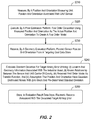
- FIG. 9 is a method associated with post-flight processing activities according to some embodiments.
- FIG. 10 is an interactive user interface display in accordance with some embodiments.
- FIG. 11 illustrates gimbals with three degrees of freedom for a sensor according to some embodiments.
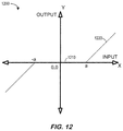
- FIG. 12 illustrates a non-linear dead-zone for a gimbal in accordance with some embodiments.
- FIG. 13 is a high-level block diagram of a system to improve target aiming accuracy in substantially real-time in accordance with yet another embodiment.
- FIG. 14 is a method to improve target aiming accuracy in accordance with some embodiments.
- FIG. 15 illustrates a monitoring platform in accordance with some embodiments.
- FIG. 16 is a tabular portion of an asset inspection database according to some embodiments.
- UAV Unmanned Aerial Vehicle
- UAS Unmanned Aerial System
- Such embodiments may be useful when inspecting industrial assets associated with various entities, including business or corporate entities, governments, individuals, non-profit organizations, and so forth.
- assets may be generally discrete or limited in their extent (e.g., a vehicle such as a plane, helicopter, ship, submersible, space launch vehicle, satellite, locomotive, and so forth) or may be geographically distributed (e.g., a road or rail track, a port or airport, a pipeline or electrical infrastructure, a power generation facility or manufacturing plant, and so forth).
- Some embodiments described herein may be used to inspect assets of these types (as well as others not listed) in an autonomous or semi-autonomous manner using robotic agents.
- assets such as distributed assets and/or individual assets
- assets may be used to perform any number of operations.
- assets may deteriorate due to weather, physical wear, or the like.
- one or more components of an asset may wear or deteriorate due to rain and wind or other environmental conditions or due to inadequate maintenance.
- spontaneous failures of one or more components or systems of an asset may occur which may be unrelated to wear or maintenance conditions but may instead be attributable to an undetected defect or an unknown stressor.
- understanding the health of the asset depends on inspecting for such defects in a timely and effective manner.
- the knowledge of positioning and targeting/aiming accuracies of an inspection UAV can be very important to the success of an inspection task. It may also impact decision making and motion/action planning processes for an inspection. For example, an operator may plan a motion path for a high accuracy UAV to navigate very close to an asset to obtain high resolution images. Note, however, that positioning and aiming accuracies may depend on both flight controller and on-board sensors, and the accuracies can vary under different weather and environmental conditions.
- a UAV may achieve high positioning accuracy under normal weather condition with clear sky view (e.g., to obtain a strong Global Positioning Satellite (“GPS”) signal, while the same system can fail to achieve centimeter-level positioning accuracy under windy condition (or in an environment with few line-of-sight GPS satellites).
- GPS Global Positioning Satellite
- many UAV vendors only provide specifications for on-board sensors under certain conditions. Thus, for a successful inspection plan in specific environmental and weather conditions, calibration experiments and analysis tools may be needed to obtain accurate knowledge of UAV positioning and aiming accuracies.
- FIG. 1 is a high-level block diagram of a system 100 according to some embodiments of the present invention.
- the system 100 includes a geometry evaluation platform 180 that receives information from an UAV 150 and a targeting goal data store 110 .
- the geometry evaluation platform 180 evaluates targeting aim accuracy of the UAV 150 (e.g., post-flight) and stores information to an evaluation result data store 120 (e.g., for post-flight or “off-line” processing).
- the UAV 150 includes a pose estimation platform 170 that receives information from one or more sensing systems 160 , such as an Inertial Measurement Unit (“IMU”) and Light Detection and Ranging (“LIDAR”) device 165 , and forwards information to the geometry evaluation platform 180 .
- sensing systems 160 such as an Inertial Measurement Unit (“IMU”) and Light Detection and Ranging (“LIDAR”) device 165 .
- IMU Inertial Measurement Unit
- LIDAR Light Detection and Ranging
- the targeting goal data store 110 may store a set of electronic records defining a three-dimensional model of an industrial asset including a plurality of points of interest
- the evaluation result data store 120 may store a set of electronic records reflecting target aiming accuracy associated with an inspection plan defining a path of movement for the UAV 150 .
- the UAS UAV and/or geometry evaluation platform 180 may also exchange information with remote human operator devices (e.g., via a firewall).
- a user interface of the geometry evaluation system 180 may communicate with front-end operator devices, access information in the targeting goal data store 110 and/or the evaluation result data store 120 , and facilitate the presentation of interactive user interface displays to a human operator.
- the UAV 150 and/or geometry evaluation platform 180 might also be associated with a third party, such as a vendor that performs a service for an enterprise.
- the geometry evaluation platform 180 might be, for example, associated with a Personal Computer (“PC”), laptop computer, smartphone, an enterprise server, a server farm, and/or a database or similar storage devices. According to some embodiments, an “automated” geometry evaluation platform 180 may automatically evaluate target aiming accuracy. As used herein, the term “automated” may refer to, for example, actions that can be performed with little (or no) intervention by a human.
- devices may exchange information via any communication network which may be one or more of a Local Area Network (“LAN”), a Metropolitan Area Network (“MAN”), a Wide Area Network (“WAN”), a proprietary network, a Public Switched Telephone Network (“PSTN”), a Wireless Application Protocol (“WAP”) network, a Bluetooth network, a wireless LAN network, and/or an Internet Protocol (“IP”) network such as the Internet, an intranet, or an extranet.
- LAN Local Area Network
- MAN Metropolitan Area Network
- WAN Wide Area Network
- PSTN Public Switched Telephone Network
- WAP Wireless Application Protocol
- Bluetooth a Bluetooth network
- wireless LAN network a wireless LAN network
- IP Internet Protocol
- any devices described herein may communicate via one or more such communication networks.
- the geometry evaluation platform 180 may store information into and/or retrieve information from the targeting goal data store 110 and/or the evaluation result data store 120 .
- the targeting goal data store 110 and/or the evaluation result data store 120 may contain data that was downloaded, received from a UAV vendor or manufacturer, that was originally input by an operator of an enterprise, that was generated by the geometry evaluation platform 180 , etc.
- the targeting goal data store 110 and/or the evaluation result data store 120 may be locally stored or reside remote from the geometry evaluation platform 180 .
- the targeting goal data store 110 and/or the evaluation result data store 220 may be used by the geometry evaluation platform 180 to provide post-flight processing associated with target aiming accuracy.
- any number of such devices may be included.
- various devices described herein might be combined according to embodiments of the present invention.
- the geometry evaluation platform 180 , targeting goal data store 110 and/or the evaluation result data store 120 be co-located and/or may comprise a single apparatus.
- autonomous inspection “robots” may fly themselves and/or be wirelessly controlled via a control system (e.g., by a human monitor using the remote device 160 ).
- the term “robot” might refer to a machine (e.g., an electro-mechanical apparatus) capable of carrying out a set of tasks (e.g., movement of all or part of the machine, operation of one or more type of sensors to acquire sensed data or measurements, and so forth) automatically (e.g., at least partially without input, oversight, or control by an operator), such as a set of tasks programmed by a computer.
- a set of tasks e.g., movement of all or part of the machine, operation of one or more type of sensors to acquire sensed data or measurements, and so forth
- an autonomous inspection robot may include one or more sensors to detect one or more characteristics of an industrial asset.
- the UAV 150 may also include a processing system that includes one or more processors operatively coupled to memory and storage components.
- the system 100 may automatically evaluate target aiming.
- actual positioning accuracy may involves two major error sources: 1) GPS and IMU sensor noise, and 2) flight control error.
- the sources of error may be more complex, including GPS and IMU sensor noise, gimbal sensor noise, gimbal control error, flight control error, etc. which all may contribute to an overall total aiming error. That is, the actual total aiming error may comprise a combination of control errors (flight controller, gimbal controller) and sensing errors (GPS, IMU sensors) and these error sources may be deeply coupled in a UAV system.
- FIG. 1 illustrates a system 100 that might be performed by some or all of the elements of the system 100 described with respect to FIG. 1 , or any other system, according to some embodiments of the present invention.
- the flow charts described herein do not imply a fixed order to the steps, and embodiments of the present invention may be practiced in any order that is practicable. Note that any of the methods described herein may be performed by hardware, software, or any combination of these approaches.
- a computer-readable storage medium may store thereon instructions that when executed by a machine result in performance according to any of the embodiments described herein.
- a position and orientation measuring unit may measure a position and orientation associated with a UAV sensor (e.g., a camera).
- the position and orientation measuring unit may include or receive information from an IMU and/or a LIDAR sensor.
- the sensor inspecting the asset might be associated with a camera, a video camera, an infra-red camera, a microphone, a chemical detector, a LIDAR sensor, a radiation detector, etc.
- the phrase “industrial asset” may be associated with, for example, a flare stack, a wind turbine, a power grid, an aircraft, a locomotive, a pipe, a storage tank, a dam, etc.
- a pose estimation platform may execute a first order calculation using the measured position and orientation as the actual position and orientation to create a first order model.
- a geometry evaluation platform may receive planned sensor position and orientation from a targeting goal data store.
- the system may calculate a standard deviation for a target aiming error of the sensor's projected location on an industrial asset being inspected utilizing:
- the position of a UAV may be measured by GPS and/or Inertial Navigation System (“INS”) and the inspection tool or sensor (such as a camera) may be controlled by a gimbal (e.g., motor) to aim the sensor at certain locations on asset.
- INS Inertial Navigation System
- the relative location of the inspection tool/camera to the UAV center of gravity may be known such that the system can calculate the position of the camera by using transformation matrices.
- Some embodiments described herein may be associated with a model-based method to quantify the aiming error by using planned camera position and orientation, together with actual/measured camera position and orientation.
- the system may use the location and geometry of the asset and the position and orientation of the camera as the inputs to the model and calculate a projected location on asset.
- a geometry evaluation platform may calculate a first target aiming error associated with sensor pitch error and a second target aiming error associated with sensor yaw error.
- FIG. 3A is an example 300 in three dimensions 310 of a UAV 320 aiming error (“ERR1”) due to gimbal pitch error in accordance with some embodiments.
- ERP1 UAV 320 aiming error
- a plane 322 is defined by the locations of the UAV 320 and an industrial asset model 330 (e.g., a cylindrical model) and ERR1 represents deviation 342 (dashed lines in FIG. 3A ) from a desired target aiming line-of-sight 344 (dotted line in FIG. 3A ).
- FIG. 3B is an example 350 in three dimensions 360 of a UAV 370 aiming error (“ERR2”) due to gimbal yaw error in accordance with some embodiments.
- a plane 322 is defined by the locations of the UAV 370 and an industrial asset model 380 (e.g., a cylindrical model). In particular the plane 372 is perpendicular to the plate 322 described with respect to FIG. 3A .
- ERR2 represents deviation 392 (dashed lines in FIG. 3B ) from a desired target aiming line-of-sight 394 (dotted line in FIG. 3B ).
- the system may assume that the industrial asset 380 is a cylinder as a first order approximation. Moreover, more complex models than a cylinder might cause greater projected error due to orientation error and three-dimensional modeling error, and, as a result, a cylinder model might be utilized even when a three-dimensional model of the industrial asset is available.
- the first order calculation one assumption might be made: that the measured position and orientation are the actual position and orientation (e.g., the sensor noise is not included).
- the system may assume that the position and orientation measurements have noises that are Gaussian distributed with zero means and standard deviation (e.g., from a vendor's specification).
- FIG. 4 illustrates 400 a three-dimensional 410 example of positioning accuracy results comparing actual (“A”) and predicted “(P”) locations for a UAV 420 relative to a wind turbine 430 in accordance with some embodiments.
- FIG. 5 illustrates 500 another three-dimensional example of aiming accuracy results comparing actual (“A”) and predicted (“P”) aiming relative to a flare stack 530 according to some embodiments.
- FIG. 6 is a high-level block diagram of target aiming accuracy evaluation system 600 in accordance with another embodiment.
- a UAV 650 may include a pose estimation platform 670 that receives information from sensing systems 660 (e.g., an IMU 662 and a LIDAR device 664 ).
- the UAV 650 also includes an image feature extraction unit 690 that receives information from the sensing systems 660 (e.g., the LIDAR device 664 ) including a camera 666 (e.g., a high-resolution camera, a video camera, an IR camera, etc.).
- a camera 666 e.g., a high-resolution camera, a video camera, an IR camera, etc.
- Extended Kalman filter may refer to, for example, any non-linear version of a Linear Quadratic Estimation (“LQE”), including algorithms that use a series of measurements observed over time (containing statistical noise and other inaccuracies) and produce estimates of unknown variables that may be more accurate than those based on a single measurement alone (e.g., by estimating a joint probability distribution over the variables for each timeframe).
- LQE Linear Quadratic Estimation
- the geometry evaluation platform 680 may use data from the extended Kalman filter 692 , a targeting goal data store 6110 and the camera 666 to evaluate target aiming accuracy for the UAV 650 and store results in an evaluation result data store 620 .
- FIG. 7 is a vision feature-based method to evaluate target aiming accuracy according to some embodiments.
- the system may store, in a targeting goal data store, electronic records representing planned sensor position and orientation.
- an inspection plan may further include a sensor type associated with a point of interest, an anomaly associated with a point of interest, a perspective associated with a point of interest, an amount of time associated with a point of interest (e.g., how long data should be collected), etc.
- a position and orientation measuring unit may measure a position and orientation associated with the sensor.
- an extended Kalman filter coupled to a pose estimation platform and an image feature extraction unit, may generate an adjusted transformation of image data.
- a geometry evaluation platform may compare the adjusted transformation of the image data with the planned sensor position and orientation based on a feature matching algorithm to calculate a target aiming error. The system may then store electronic records associated with the calculated target aiming error in an evaluation result data store at 750 .
- a vision feature-based method may be provided.
- an underlying assumption of the model-based method was that the sensor noise has zero mean and is secondary as compared to the control error.
- embodiments may use images taken at planned locations to directly calculate a bias of a feature on each image as the target aiming error.
- Such an approach may use a three-dimensional model of an industrial asset and select an appropriate feature (e.g., a metal corner of the asset) during an action planning phase.
- the approach may also detect the feature from images and calculate the feature location to the image center point as the bias. Note that this approach might utilize accurate information of the asset location and geometry (that is, a three-dimensional model).
- the extended Kalman filter may incorporate information from pose estimation and image feature extraction to have an adjusted transformation of the images.
- the images may then be transformed using the result from the extended Kalman filter.
- the transformed image may be compared with the targeting goal to compute the evaluation result.
- FIG. 8 is an example 800 demonstrating matching-based target aiming accuracy evaluation comparing a theoretical image 810 with an actual picture 820 of industrial asset features (“X” in FIG. 8 ) in accordance with some embodiments.
- FIG. 9 is a method associated with post-flight processing activities according to some embodiments.
- the system may perform a model-based evaluation of target aiming accuracy.
- the system may then perform a vision feature-based evaluation of target aiming accuracy at S 920 .
- the system might select to either only one approach or both approaches might be implemented simultaneously. Further note that different approaches might be more appropriate in different circumstances (e.g., a sunny day versus an evening flight or a flight on a cloudy day).
- post-flight processing may be performed to establish geo-tagging for the industrial asset. For example, FIG.
- FIG. 10 is an interactive user interface display 100 that might be used to define geo-tags for an industrial asset 1010 using a recorded view 1020 , street view 1030 , etc. associated with an inspection drone flight 1040 .
- an operator might define geo-tags 1050 in accordance target aiming accuracy evaluations.
- post-flight processing may be performed to improve future UAV inspections. For example, future flights might be adjusted so that the drone is positioned closer to an important industrial asset feature because the target aiming was not particular accurate in the initial flight.
- some embodiments may improve target aiming accuracy during a flight (“on-line”).
- on-line a UAV in an autonomous inspection can be challenging because disturbances in the environment and errors in the control systems may result in vibration problems.
- many commercial UAV models use special gimbals that have on-board stabilization capabilities to reduce vibration.
- special hardware mechanisms may be designed to generate over-damping motions for sensors when the UAV is vibrating. Such methods may reduce sensor vibration and improve the quality of sensor data.
- an over-damping mechanism will increase settling time and, in some industrial inspection tasks, high targeting accuracy may be desired when pointing a gimbal or sensor to a target point.
- an onboard control system to handle this problem using the location of the UAV, the orientation of the gimbal/sensor, the know location of industrial assets, and the predefined inspection points as input information.
- the system may use this information to continuously compute control commands that rotate the gimbal before taking a picture or sensing environmental information. This may modulate the original first-order system to a second-order and improve targeting accuracy.
- FIG. 11 illustrates a system 1100 with gimbals 1120 , 1130 , 1140 that provide three degrees of freedom for a UAV sensor 1110 (e.g., a camera) according to some embodiments.
- the three gimbals 1120 , 1130 , 1140 may be controlled by three motors that rotate.
- Each motor control component can be considered as a first-order over-damping mechanism, and the transfer function for each component can be described as:
- FIG. 12 is an example 1200 with a graph 1210 of a function 1220 between an input and an output that illustrates a non-linear dead-zone for a gimbal in accordance with some embodiments.
- ⁇ , K p and a are known, a non-linear controller may be designed to move the gimbal quickly and robustly. Unfortunately, ⁇ , K p , and a are not usually known. Note that in some situations the targeting angle may be very important while the rising and settling times are less important.
- FIG. 13 is a high-level block diagram of a system 1300 to improve target aiming accuracy in substantially real-time in accordance with yet another embodiment.
- Two sensors are used to get the location of the UAV, which will be used to compute the targeting accuracy.
- a differential GPS 1310 may use a Real Time Kinematic (“RTK”) technique to enhance the precision of position data derived from satellite-based positioning systems such as Global Navigation Satellite Systems (“GNSS”) including GPS, Russia's GLONASS, Europe's Galileo, and China's BeiDou.
- RTK Real Time Kinematic
- GNSS Global Navigation Satellite Systems
- This method may provide a precise pose estimation for hardware platforms at a relative low update frequency is low (e.g., approximately 1 Hz).
- An IMU 1320 may be an electronic device that measures and reports a body's specific force, angular rate, and/or the magnetic field surrounding the body using a combination of accelerometers, gyroscopes, and/or magnetometers.
- the update frequency of an IMU 1320 may be relatively high (e.g., over 100 Hz) as compared to the differential GPS 1310 . However, the relatively accuracy of the IMU may be low and drift cannot be ignored.
- a first extended Kalman filter 1330 may provide a good estimation of the UAV pose.
- the IMU 1310 may be sampled at the same rate as the differential GPS 1310 and, as a result, the output may run at approximately 1 Hz.
- a second extended Kalman filter 1340 may be used to provide fast estimation.
- the second Kalman filter 1314 may run at approximately 100 Hz, for example.
- the major input of the second Kalman filter 1340 may from the IMU 1320 and the differential GPS 1310 (e.g., RTK) may be used as correction signal.
- the estimated pose is used to compute the targeting point on an industrial asset.
- the projection line of the sensor may be computed using the pose of the platform and the orientation of the gimbal with respect to the platform (e.g., the UAV).
- the projection line can then be extracted from T.
- a projection computing unit 1350 may receive information from the second extended Kalman filter 1340 , a gimbal encoder 1390 , and a known asset location 1360 .
- the intersection point can then be computed using T and the model of the industrial asset.
- the point computed and the predefined point on the industrial asset may be used as an input of a Proportion Integration (“PI”) controller 1370 along with the known asset location 1360 :
- a d K p ( P desired ⁇ P actual )+ K i ⁇ ( P desired ⁇ P actual ) where P desired is a desired position and P actual is an actual position.
- the output of the PI controller 1370 may be provided to a gimbal orientation control 1380 which, in turn, can provide data to the differential GPS 1310 , the IMU 1320 , and/or the gimbal encoder 1390 .
- a d is below a predetermined threshold value, a picture may be taken and the robot platform (UAV) may move to the next point of interest or waypoint.
- the system 1300 may use the differential GPS 1310 (RTK), the IMU 1320 , and encoders to compute the projection line.
- RTK differential GPS 1310
- IMU 1320 the IMU 1320
- encoders the number of extended Kalman filters may be increased to provide an even more robust estimation.
- FIG. 14 is a method to improve target aiming accuracy in accordance with some embodiments.
- the system may store, in a three-dimensional model data store, electronic records comprising a three-dimensional model of an industrial asset, the three-dimensional model may include, according to some embodiments, locations of a plurality of points of interest associated with the industrial asset.
- a UAV location and pose platform may receive data from or measure data with a first sensor (e.g., RTK, GPS, etc.) providing a relatively accurate pose estimation at a relatively low update frequency.
- a first sensor e.g., RTK, GPS, etc.
- the UAV location and pose platform may receive data from or measure data with a second sensor (e.g., IMU) providing a less accurate pose estimation, as compared to the first sensor, at a relatively high update frequency.
- a second sensor e.g., IMU
- an estimate of the pose may be provided from a first extended Kalman filter by sampling data from the first and second sensors at a rate based on the first sensor's update frequency.
- a second extended Kalman filter may run at a rate based on the second sensor's update frequency using data from the second sensor as a major input and data from the first sensor as a correction signal.
- a projection computing platform may receive:
- the gimbal is associated with a motor that rotates the sensor.
- the PI controller may continuously compute motor control commands to rotate the gimble before sensing a characteristic of the industrial asset.
- the motor is associated with a first-order damping mechanism having a dead zone a and a transfer function of:
- T ⁇ ( s ) K p 1 + ⁇ ⁇ ⁇ s
- Kp is a gain
- ⁇ is a time constant.
- FIG. 15 is block diagram of a monitoring platform 1500 that may be, for example, associated with the systems 100 , 600 , 1300 of FIGS. 1, 6, and 13 , respectively.
- the monitoring platform 1500 comprises a processor 1510 , such as one or more commercially available Central Processing Units (“CPUs”) in the form of one-chip microprocessors, coupled to a communication device 1520 configured to communicate via a communication network (not shown in FIG. 15 ).
- the communication device 1520 may be used to communicate, for example, with one or more remote robots, UAV, human operator devices, etc.
- the monitoring platform 1500 further includes an input device 1540 (e.g., a computer mouse and/or keyboard to input inspection information, asset modeling data, drone control signals, etc.) and/an output device 1550 (e.g., a computer monitor to render a user interface display, transmit control signals to inspection robots, etc.).
- an input device 1540 e.g., a computer mouse and/or keyboard to input inspection information, asset modeling data, drone control signals, etc.
- an output device 1550 e.g., a computer monitor to render a user interface display, transmit control signals to inspection robots, etc.
- a mobile device and/or PC may be used to exchange information with the monitoring platform 1500 .
- the processor 1510 also communicates with a storage device 1530 .
- the storage device 1530 may comprise any appropriate information storage device, including combinations of magnetic storage devices (e.g., a hard disk drive), optical storage devices, mobile telephones, and/or semiconductor memory devices.
- the storage device 1530 stores a program 1512 and/or an asset inspection engine 1514 for controlling the processor 1510 .
- the processor 1510 performs instructions of the programs 1512 , 1514 , and thereby operates in accordance with any of the embodiments described herein.
- the processor 1510 may measure a position and orientation associated with a UAV sensor.
- the processor 1510 may execute a first order calculation using the measured position and orientation as the actual position and orientation to create a first order model.
- the processor 1510 may receive planned sensor position and orientation from a targeting goal data store and calculate a standard deviation for a target aiming error utilizing: (i) location and geometry information associated with the industrial asset, (ii) a known relationship between the sensor and a center-of-gravity of the UAV, (iii) the first order model as a transfer function, and (iv) an assumption that the position and orientation of the sensor have Gaussian-distributed noises with zero mean and a pre-determined standard deviation.
- the processor 1510 may measure a position and orientation associated with the sensor.
- the processor 1510 may receive image data from a camera of the UAV.
- An extended Kalman filter may generate an adjusted transformation of the image data, and the processor 1510 may: receive the adjusted transformation of the image, receive the planned sensor position and orientation, and compare the adjusted transformation of the image data with the planned sensor position and orientation based on a feature matching algorithm to calculate a target aiming error.
- a three-dimensional model data may store containing electronic records comprising a three-dimensional model of an industrial asset, the three-dimensional model including locations of a plurality of points of interest associated with the industrial asset.
- a UAV location and pose platform may include: a first sensor providing a relatively accurate pose estimation at a relatively low update frequency; and a second sensor providing a less accurate pose estimation, as compared to the first sensor, at a relatively high update frequency.
- a first extended Kalman filter may provide an estimation of the pose by sampling data from the first and second sensors at a rate based on the first sensor's update frequency.
- a second extended Kalman filter may run at a rate based on the second sensor's update frequency using data from the second sensor as a major input and data from the first sensor as a correction signal.
- the processor 1510 may then receive: (i) an estimated current location and pose of the UAV from the UAV location and pose platform, (ii) an orientation of a gimbal coupled to the UAV to rotate the sensor, (iii) a location of the industrial asset from the three-dimensional model data store, and (iv) an indication of a predefined inspection point associated with the industrial asset.
- the programs 1512 , 1514 may be stored in a compressed, uncompiled and/or encrypted format.
- the programs 1512 , 1514 may furthermore include other program elements, such as an operating system, clipboard application, a database management system, and/or device drivers used by the processor 1510 to interface with peripheral devices.
- information may be “received” by or “transmitted” to, for example: (i) the monitoring platform 1500 from another device; or (ii) a software application or module within the monitoring platform 1500 from another software application, module, or any other source.
- the storage device 1530 further stores target aiming database 1600 .
- target aiming database 1600 An example of a database that may be used in connection with the monitoring platform 1500 will now be described in detail with respect to FIG. 16 . Note that the database described herein is only one example, and additional and/or different information may be stored therein. Moreover, various databases might be split or combined in accordance with any of the embodiments described herein.
- a table is shown that represents the target aiming database 1600 that may be stored at the monitoring platform 1500 according to some embodiments.
- the table may include, for example, entries identifying asset inspection processes that have been executed in accordance with any of the embodiments described herein.
- the table may also define fields 1602 , 1604 , 1606 , 1608 , 1610 , 1612 for each of the entries.
- the fields 1602 , 1604 , 1606 , 1608 , 1610 , 1612 may, according to some embodiments, specify: an asset inspection identifier 1602 , an asset identifier 1604 , three-dimensional model data 1606 , inspection plan data 1608 , collected sensor data 1610 , and target aiming accuracy 1612 .
- the asset inspection database 1600 may be created and updated, for example, when an industrial asset is installed, inspections are performed, etc.
- the asset inspection identifier 1602 may be, for example, a unique alphanumeric code identifying an inspection process that was performed by an autonomous inspection robot under the supervision of a human monitor (and might include the date and/or time of the inspection).
- the asset identifier 1604 might identify the industrial asset that was being inspected.
- the three-dimensional model data 1606 e.g., including Points of Interest (“POI”)
- POI Points of Interest
- the inspection plan data 1608 might comprise the information that used to conduct the inspection.
- the collected sensor data 1610 might include the pictures, videos, etc. used to record characteristics of the industrial asset being inspected.
- the target aiming accuracy 1612 might reflect a percentage deviation from a desired location or angle, a category (“accurate” or “inaccurate”), a distance, etc.
- some embodiments may provide systems and methods to evaluate and/or improve target aiming accuracy in an automated and efficient manner. This may reduce the cost of industrial asset systems and/or inspection UAV without requiring extra hardware or substantial modification to software. Moreover, embodiments might be incorporated both on-line and/or off-line to use sensor information fusion methods when estimating targeting points on industrial assets. Note that embodiments be used for different industrial platforms and/or different vendors. Embodiments described herein may improve the targeting accuracy of industrial robotic inspection systems, which may improve the analytics results and the whole system performance.
Landscapes
- Engineering & Computer Science (AREA)
- Physics & Mathematics (AREA)
- Radar, Positioning & Navigation (AREA)
- Remote Sensing (AREA)
- General Physics & Mathematics (AREA)
- Electromagnetism (AREA)
- Computer Networks & Wireless Communication (AREA)
- Automation & Control Theory (AREA)
- Aviation & Aerospace Engineering (AREA)
- Signal Processing (AREA)
- Computer Vision & Pattern Recognition (AREA)
- Theoretical Computer Science (AREA)
- Multimedia (AREA)
- Bioinformatics & Cheminformatics (AREA)
- Bioinformatics & Computational Biology (AREA)
- Evolutionary Biology (AREA)
- Probability & Statistics with Applications (AREA)
- Life Sciences & Earth Sciences (AREA)
- Navigation (AREA)
Abstract
Description
T=T UAV gimbal T asset UAV
where TUAV gimabal represents a relation between the gimbal and the UAV and Tasset UAV represents a relation between the UAV and the industrial asset.
T=T UAV gimbal T asset UAV
where TUAV gimabal represents a relation between the gimbal and the UAV and Tasset UAV represents a relation between the UAV and the industrial asset.
-
- location and geometry information associated with the industrial asset (e.g., associated with a cylindrical model or representation of the asset),
- a known relationship between the sensor and a center-of-gravity of the UAV,
- the received first order model as a transfer function, and
- an assumption that the position and orientation of the sensor have Gaussian-distributed noises with zero mean and a pre-determined standard deviation.
At S250, electronic records associated with the calculated target aiming error may then be stored in an evaluation result data store.
where Kp is a gain and τ is a time constant. However, due to mechanical limitations, sometimes a dead-zone is added to the system to avoid frequent vibrations. A dead-zone may represent, for example, a kind of non-linearity in which the system does not respond to a given input until the input reaches a particular level (or it can refer to a condition in which output becomes zero when the input crosses certain limiting value).
T=T UAV gimbal T asset UAV
where TUAV gimabal represents a relation between the gimbal and the UAV and Tasset UAV represents a relation between the UAV and the industrial asset. The projection line can then be extracted from T. Note that a
A d =K p(P desired −P actual)+K i∫(P desired −P actual)
where Pdesired is a desired position and Pactual is an actual position. The output of the
-
- an estimated current location and pose of the UAV from the UAV location and pose platform,
- an orientation of a gimbal coupled to the UAV to rotate the sensor,
- a location of the industrial asset from the three-dimensional model data store, and
- an indication of a predefined inspection point associated with the industrial asset.
At S1470, a PI controller may compute a targeting point on the industrial asset using the following serial transformation:
T=T UAV gimbal T asset UAV
where TUAV gimabal represents a relation between the gimbal and the UAV and Tasset UAV represents a relation between the UAV and the industrial asset.
where Kp is a gain and τ is a time constant. Moreover, the PI controller may sense the characteristic of the industrial asset when a motor control command Ad is below a pre-determined threshold value:
A d =K p(P desired −P actual)+K i∫(P desired −P actual)
where Pdesired is a desired position and Pactual is an actual position.
T=T UAV gimbal T asset UAV
where TUAV gimabal represents a relation between the gimbal and the UAV and Tasset UAV represents a relation between the UAV and the industrial asset.
Claims (19)
T=T UAV gimbal T asset UAV
Priority Applications (2)
| Application Number | Priority Date | Filing Date | Title |
|---|---|---|---|
| US15/861,054 US10690525B2 (en) | 2018-01-03 | 2018-01-03 | Systems and methods associated with unmanned aerial vehicle targeting accuracy |
| PCT/US2018/062427 WO2019135834A1 (en) | 2018-01-03 | 2018-11-26 | Systems and methods associated with unmanned aerial vehicle targeting accuracy |
Applications Claiming Priority (1)
| Application Number | Priority Date | Filing Date | Title |
|---|---|---|---|
| US15/861,054 US10690525B2 (en) | 2018-01-03 | 2018-01-03 | Systems and methods associated with unmanned aerial vehicle targeting accuracy |
Publications (2)
| Publication Number | Publication Date |
|---|---|
| US20190204123A1 US20190204123A1 (en) | 2019-07-04 |
| US10690525B2 true US10690525B2 (en) | 2020-06-23 |
Family
ID=64664504
Family Applications (1)
| Application Number | Title | Priority Date | Filing Date |
|---|---|---|---|
| US15/861,054 Active 2038-09-03 US10690525B2 (en) | 2018-01-03 | 2018-01-03 | Systems and methods associated with unmanned aerial vehicle targeting accuracy |
Country Status (2)
| Country | Link |
|---|---|
| US (1) | US10690525B2 (en) |
| WO (1) | WO2019135834A1 (en) |
Cited By (2)
| Publication number | Priority date | Publication date | Assignee | Title |
|---|---|---|---|---|
| US20220083774A1 (en) * | 2020-09-14 | 2022-03-17 | Tata Consultancy Services Limited | Method and system for asset inspection using unmanned aerial vehicles |
| US11310423B2 (en) * | 2019-12-16 | 2022-04-19 | Industrial Technology Research Institute | Image capturing method and image capturing apparatus |
Families Citing this family (21)
| Publication number | Priority date | Publication date | Assignee | Title |
|---|---|---|---|---|
| US10916150B2 (en) | 2018-05-03 | 2021-02-09 | Arkidan Systems Inc. | Computer-assisted aerial surveying and navigation |
| US10970586B2 (en) * | 2018-06-28 | 2021-04-06 | General Electric Company | Systems and methods of 3D scene segmentation and matching for robotic operations |
| CN110658540A (en) * | 2019-09-18 | 2020-01-07 | 华南农业大学 | A method of using UAV low-altitude flight target positioning technology to test the accuracy of rice transplanter satellite navigation automatic operation |
| CN112198887B (en) * | 2019-12-31 | 2022-04-01 | 北京理工大学 | Multi-rotor unmanned aerial vehicle onboard computer performance evaluation system method |
| CN111366148B (en) * | 2020-03-27 | 2022-11-22 | 西安应用光学研究所 | Target positioning method suitable for multiple observations of airborne photoelectric observing and sighting system |
| CN111722295B (en) * | 2020-07-04 | 2021-04-23 | 东南大学 | Underwater strapdown gravity measurement data processing method |
| CN112346104B (en) * | 2020-09-11 | 2023-08-08 | 中国人民解放军国防科技大学 | A UAV Information Fusion Positioning Method |
| JP7522007B2 (en) * | 2020-10-30 | 2024-07-24 | 川崎重工業株式会社 | Unmanned delivery system and unmanned delivery method |
| CN112616132B (en) * | 2020-12-16 | 2022-04-01 | 同济大学 | A low-altitude air-ground UAV channel multipath tracking method based on geometric prior model |
| CN112577706B (en) * | 2020-12-25 | 2022-05-27 | 中国航天空气动力技术研究院 | Method for acquiring pose of embedded wind tunnel free flight test model |
| CN112672398B (en) * | 2020-12-28 | 2023-06-16 | 上海微波技术研究所(中国电子科技集团公司第五十研究所) | 3D-GPSR routing method based on self-adaptive kalman prediction |
| WO2022141620A1 (en) * | 2021-01-04 | 2022-07-07 | Qualcomm Incorporated | Integrated visual-inertial odometry and image stabilization for image processing |
| CN113156991B (en) * | 2021-02-05 | 2023-02-17 | 北京林业大学 | A flight evaluation system and method based on a small multi-rotor aircraft |
| CN113076634B (en) * | 2021-03-24 | 2023-04-07 | 哈尔滨工业大学 | Multi-machine cooperative passive positioning method, device and system |
| CN113190041B (en) * | 2021-04-30 | 2022-05-10 | 哈尔滨工业大学 | An online target assignment method for UAV swarms based on constraint relaxation technology |
| US12135381B2 (en) * | 2021-08-31 | 2024-11-05 | James DOTAN | Precision positioning and pointing instrument |
| CN114460963B (en) * | 2021-12-27 | 2024-10-22 | 河南福多电力工程有限公司 | Automatic inspection system of unmanned aerial vehicle of transformer substation and operation method thereof |
| CN114509445B (en) * | 2022-01-11 | 2024-08-06 | 长江水利委员会长江科学院 | Cluster analysis-based pollutant identification early warning method and system |
| CN115293006B (en) * | 2022-09-01 | 2024-08-09 | 中国船舶集团有限公司第七一一研究所 | Ship sensor measuring point optimizing method and device |
| CN116455463B (en) * | 2023-05-05 | 2024-06-04 | 众芯汉创(北京)科技有限公司 | Communication optical cable differential operation and maintenance system based on unmanned aerial vehicle |
| CN119918292B (en) * | 2025-01-24 | 2025-10-31 | 西北工业大学 | Dynamic platform multi-infrared sensor collaborative multi-target perception digital simulation platform |
Citations (16)
| Publication number | Priority date | Publication date | Assignee | Title |
|---|---|---|---|---|
| US20050114023A1 (en) * | 2003-11-26 | 2005-05-26 | Williamson Walton R. | Fault-tolerant system, apparatus and method |
| US7092109B2 (en) | 2003-01-10 | 2006-08-15 | Canon Kabushiki Kaisha | Position/orientation measurement method, and position/orientation measurement apparatus |
| US8060270B2 (en) | 2008-02-29 | 2011-11-15 | The Boeing Company | System and method for inspection of structures and objects by swarm of remote unmanned vehicles |
| CN102510011A (en) | 2011-10-24 | 2012-06-20 | 华北电力大学 | Method for realizing the intelligent tour-inspection of power tower based on miniature multi-rotor unmanned helicopter |
| US8392045B2 (en) | 2008-09-05 | 2013-03-05 | The Boeing Company | System and methods for aircraft preflight inspection |
| US20140050352A1 (en) * | 2012-08-17 | 2014-02-20 | Ge Aviation Systems Llc | Method of identifying a tracked object for use in processing hyperspectral data |
| US8855846B2 (en) | 2005-10-20 | 2014-10-07 | Jason W. Grzywna | System and method for onboard vision processing |
| US9074848B1 (en) * | 2011-04-13 | 2015-07-07 | Litel Instruments | Precision geographic location system and method utilizing an image product |
| US20150248584A1 (en) * | 2012-09-28 | 2015-09-03 | Omg Plc | Determination of position from images and associated camera positions |
| US20160078759A1 (en) * | 2012-08-06 | 2016-03-17 | Cloudparc, Inc. | Tracking a Vehicle Using an Unmanned Aerial Vehicle |
| US9513635B1 (en) | 2015-12-30 | 2016-12-06 | Unmanned Innovation, Inc. | Unmanned aerial vehicle inspection system |
| US9740200B2 (en) | 2015-12-30 | 2017-08-22 | Unmanned Innovation, Inc. | Unmanned aerial vehicle inspection system |
| US20170248967A1 (en) | 2016-02-25 | 2017-08-31 | A.M.T.S., Llc | Unmanned aircraft for positioning an instrument for inspection purposes and methods of inspecting a target surface |
| US10032285B1 (en) * | 2015-11-05 | 2018-07-24 | National Technology & Engineering Solutions Of Sandia, Llc | Multi-hypothesis moving object detection system |
| US20190197292A1 (en) * | 2017-12-21 | 2019-06-27 | X Development Llc | Image based localization for unmanned aerial vehicles, and associated systems and methods |
| US20190204093A1 (en) * | 2017-12-29 | 2019-07-04 | Walmart Apollo, Llc | System and method for determining autonomous vehicle location using incremental image analysis |
-
2018
- 2018-01-03 US US15/861,054 patent/US10690525B2/en active Active
- 2018-11-26 WO PCT/US2018/062427 patent/WO2019135834A1/en not_active Ceased
Patent Citations (18)
| Publication number | Priority date | Publication date | Assignee | Title |
|---|---|---|---|---|
| US7092109B2 (en) | 2003-01-10 | 2006-08-15 | Canon Kabushiki Kaisha | Position/orientation measurement method, and position/orientation measurement apparatus |
| US20050114023A1 (en) * | 2003-11-26 | 2005-05-26 | Williamson Walton R. | Fault-tolerant system, apparatus and method |
| US8855846B2 (en) | 2005-10-20 | 2014-10-07 | Jason W. Grzywna | System and method for onboard vision processing |
| US8060270B2 (en) | 2008-02-29 | 2011-11-15 | The Boeing Company | System and method for inspection of structures and objects by swarm of remote unmanned vehicles |
| US8392045B2 (en) | 2008-09-05 | 2013-03-05 | The Boeing Company | System and methods for aircraft preflight inspection |
| US9074848B1 (en) * | 2011-04-13 | 2015-07-07 | Litel Instruments | Precision geographic location system and method utilizing an image product |
| CN102510011B (en) | 2011-10-24 | 2014-10-29 | 华北电力大学 | Method for realizing the intelligent tour-inspection of power tower based on miniature multi-rotor unmanned helicopter |
| CN102510011A (en) | 2011-10-24 | 2012-06-20 | 华北电力大学 | Method for realizing the intelligent tour-inspection of power tower based on miniature multi-rotor unmanned helicopter |
| US20160078759A1 (en) * | 2012-08-06 | 2016-03-17 | Cloudparc, Inc. | Tracking a Vehicle Using an Unmanned Aerial Vehicle |
| US20140050352A1 (en) * | 2012-08-17 | 2014-02-20 | Ge Aviation Systems Llc | Method of identifying a tracked object for use in processing hyperspectral data |
| US20150248584A1 (en) * | 2012-09-28 | 2015-09-03 | Omg Plc | Determination of position from images and associated camera positions |
| US9607219B2 (en) | 2012-09-28 | 2017-03-28 | 2D3 Limited | Determination of position from images and associated camera positions |
| US10032285B1 (en) * | 2015-11-05 | 2018-07-24 | National Technology & Engineering Solutions Of Sandia, Llc | Multi-hypothesis moving object detection system |
| US9513635B1 (en) | 2015-12-30 | 2016-12-06 | Unmanned Innovation, Inc. | Unmanned aerial vehicle inspection system |
| US9740200B2 (en) | 2015-12-30 | 2017-08-22 | Unmanned Innovation, Inc. | Unmanned aerial vehicle inspection system |
| US20170248967A1 (en) | 2016-02-25 | 2017-08-31 | A.M.T.S., Llc | Unmanned aircraft for positioning an instrument for inspection purposes and methods of inspecting a target surface |
| US20190197292A1 (en) * | 2017-12-21 | 2019-06-27 | X Development Llc | Image based localization for unmanned aerial vehicles, and associated systems and methods |
| US20190204093A1 (en) * | 2017-12-29 | 2019-07-04 | Walmart Apollo, Llc | System and method for determining autonomous vehicle location using incremental image analysis |
Non-Patent Citations (12)
| Title |
|---|
| {hacek over (R)}ezá{hacek over (o)}, Ing. Martin "Inertial stabilization, estimation and visual servoing for aerial surveillance", Oct. 2013, Czech Technical University in Prague, (cover 8pgs + 1-52pgs, 60 total pages), Part 1. |
| {hacek over (R)}ezá{hacek over (o)}, Ing. Martin "Inertial stabilization, estimation and visual servoing for aerial surveillance", Oct. 2013, Czech Technical University in Prague, Chapter 4, (pp. 102-157, 56 total pages), Part 3. |
| {hacek over (R)}ezá{hacek over (o)}, Ing. Martin "Inertial stabilization, estimation and visual servoing for aerial surveillance", Oct. 2013, Czech Technical University in Prague, Chapter 4, (pp. 53-101, 49 total pages), Part 2. |
| Angelino, Cesario Vincenzo et al., "UAV Position and Attitude Estimation using IMU, GNSS and Camera", 2012 15th International Conference on Information Fusion, Singapore, Jul. 9-12, 2012, (pp. 735-742, 8 total pages). |
| Anwar, Hamza; "A Framework for Aerial Inspection of Siltation in Waterways", International Conference on Intelligen Robots and Systems (IROS), 2015, pp. 6273-6278. |
| Dos Santos Marques, Nuno Miguel, Thesis: "Integrated Architecture for Vision-based Indoor Localization and Mapping of a Quadrotor Micro-air Vehicle", Oct. 2014, 118pgs. |
| International Search Report/Written Opinion; PCT/US2018/062427 dated May 6, 2019, pp. 19. |
| Kanellakis, Christoforos et al., "Survey on Computer Vision for UAVs: Current Developments and Trends", J Intell Robot Syst., vol. 87, 2017, DOI: 10.1007/s10846-017-0483-z, (pp. 141-168, 28 total pages). |
| Post, T.H. (Tjark) "Precise location of a UAV using visual odometry", MSc Report, Robotics and Mechatronics, Dec. 2015, 58pgs. |
| Ramani, Aditya et al., "Determining Intruder Aircraft Position using Series of Stereoscopic 2-D Images", 2017 International Conference on Unmanned Aircraft Systems (ICUAS), Miami, Jun. 13-16, 2017, ISSN: 978-1-5090-4494-8, (pp. 902-911, 10 total pages). |
| Tahar, Khairul Nizman et al., "Aerial Mapping Using Autonomous Fixed-Wing Unmanned Aerial Vehicle", 2012 IEEE 8th International Colloquium on Signal Processing and its Applications, Melaka, Mar. 23-25, 2012, ISSN: 978-1-4673-0961-5, (pp. 164-168, 5 total pages). |
| Teulière, Céline et al., "3D model-based tracking for UAV position control", Intelligent Robots and Systems, 2010, DOI: 10.1109/IROS.2010.5649700, 6pgs. |
Cited By (3)
| Publication number | Priority date | Publication date | Assignee | Title |
|---|---|---|---|---|
| US11310423B2 (en) * | 2019-12-16 | 2022-04-19 | Industrial Technology Research Institute | Image capturing method and image capturing apparatus |
| US20220083774A1 (en) * | 2020-09-14 | 2022-03-17 | Tata Consultancy Services Limited | Method and system for asset inspection using unmanned aerial vehicles |
| US11776252B2 (en) * | 2020-09-14 | 2023-10-03 | Tata Consultancy Services Limited | Method and system for asset inspection using unmanned aerial vehicles |
Also Published As
| Publication number | Publication date |
|---|---|
| WO2019135834A1 (en) | 2019-07-11 |
| US20190204123A1 (en) | 2019-07-04 |
Similar Documents
| Publication | Publication Date | Title |
|---|---|---|
| US10690525B2 (en) | Systems and methods associated with unmanned aerial vehicle targeting accuracy | |
| US10682677B2 (en) | System and method providing situational awareness for autonomous asset inspection robot monitor | |
| Phillips et al. | Automating data collection for robotic bridge inspections | |
| US10777004B2 (en) | System and method for generating three-dimensional robotic inspection plan | |
| EP3622473B1 (en) | Intelligent and automated review of industrial asset integrity data | |
| CN108921947B (en) | Method, device, equipment, storage medium and acquisition entity for generating electronic map | |
| US10607406B2 (en) | Automated and adaptive three-dimensional robotic site surveying | |
| Al-Darraji et al. | A technical framework for selection of autonomous uav navigation technologies and sensors | |
| WO2025136451A1 (en) | System, apparatus, and method for improved location identification | |
| Kanellakis et al. | Towards visual inspection of wind turbines: A case of visual data acquisition using autonomous aerial robots | |
| US20230324922A1 (en) | Autonomous Robotic Platform | |
| Hafez et al. | Integrity risk-based model predictive control for mobile robots | |
| Punzo et al. | Bipartite guidance, navigation and control architecture for autonomous aerial inspections under safety constraints | |
| CN116245510B (en) | Methods, devices, and storage media for road asset detection and management based on vehicle-road cooperation | |
| CN116858229A (en) | A bridge defect locating method | |
| Krasuski et al. | Algorithms for improving the position determination of an UAV equipped with a single-frequency GPS receiver for low-altitude photogrammetry | |
| Wang et al. | Enhancing UAV Efficiency in Bridge Inspection through BIM-based Flight Planning and Image Quality Assurance | |
| US20240427343A1 (en) | Mobile apparatus, method for determining position, and non-transitory recording medium | |
| Silva Filho et al. | Semi-autonomous industrial robotic inspection: remote methane detection in oilfield | |
| Reyes-Munoz et al. | Autonomous aerial system for intelligent close-quarter inspection | |
| Vitzilaios et al. | Intelligent Aerial Drones for Traversability Assessment of Railroad Tracks (Year\Phase 2) | |
| Gavrilets et al. | High-integrity navigation for sensor-based 3D world modeling | |
| SURESH BIJJAHALLI | Intelligent navigation systems for autonomous vehicle operations in urban environments | |
| Soto | Design of a Robotic Inspection Platform for Structural Health Monitoring | |
| Xiong | GNSS Drift Correction Control for UAVs in Urban Canyons |
Legal Events
| Date | Code | Title | Description |
|---|---|---|---|
| AS | Assignment |
Owner name: GENERAL ELECTRIC COMPANY, NEW YORK Free format text: ASSIGNMENT OF ASSIGNORS INTEREST;ASSIGNORS:ZHAO, YANG;TAN, HUAN;GRAY, STEVEN;AND OTHERS;SIGNING DATES FROM 20171215 TO 20171219;REEL/FRAME:044524/0248 |
|
| FEPP | Fee payment procedure |
Free format text: ENTITY STATUS SET TO UNDISCOUNTED (ORIGINAL EVENT CODE: BIG.); ENTITY STATUS OF PATENT OWNER: LARGE ENTITY |
|
| STPP | Information on status: patent application and granting procedure in general |
Free format text: NON FINAL ACTION MAILED |
|
| STPP | Information on status: patent application and granting procedure in general |
Free format text: RESPONSE TO NON-FINAL OFFICE ACTION ENTERED AND FORWARDED TO EXAMINER |
|
| STPP | Information on status: patent application and granting procedure in general |
Free format text: PUBLICATIONS -- ISSUE FEE PAYMENT VERIFIED |
|
| STCF | Information on status: patent grant |
Free format text: PATENTED CASE |
|
| MAFP | Maintenance fee payment |
Free format text: PAYMENT OF MAINTENANCE FEE, 4TH YEAR, LARGE ENTITY (ORIGINAL EVENT CODE: M1551); ENTITY STATUS OF PATENT OWNER: LARGE ENTITY Year of fee payment: 4 |