EP1437470A1 - Ausstellungsvorrichtung für Dreh-/Kippfenster und Dreh-/Kipptüren - Google Patents
Ausstellungsvorrichtung für Dreh-/Kippfenster und Dreh-/Kipptüren Download PDFInfo
- Publication number
- EP1437470A1 EP1437470A1 EP03104182A EP03104182A EP1437470A1 EP 1437470 A1 EP1437470 A1 EP 1437470A1 EP 03104182 A EP03104182 A EP 03104182A EP 03104182 A EP03104182 A EP 03104182A EP 1437470 A1 EP1437470 A1 EP 1437470A1
- Authority
- EP
- European Patent Office
- Prior art keywords
- connection
- connection means
- fitting
- push rod
- transmission element
- Prior art date
- Legal status (The legal status is an assumption and is not a legal conclusion. Google has not performed a legal analysis and makes no representation as to the accuracy of the status listed.)
- Granted
Links
- 230000033001 locomotion Effects 0.000 claims abstract description 10
- 230000005540 biological transmission Effects 0.000 claims description 27
- 239000000446 fuel Substances 0.000 claims 1
- 108010089746 wobe Proteins 0.000 claims 1
- 230000008878 coupling Effects 0.000 description 8
- 238000010168 coupling process Methods 0.000 description 8
- 238000005859 coupling reaction Methods 0.000 description 8
- 238000007664 blowing Methods 0.000 description 1
- 230000003247 decreasing effect Effects 0.000 description 1
- 230000002349 favourable effect Effects 0.000 description 1
- 238000009434 installation Methods 0.000 description 1
Images

Classifications
-
- E—FIXED CONSTRUCTIONS
- E05—LOCKS; KEYS; WINDOW OR DOOR FITTINGS; SAFES
- E05D—HINGES OR SUSPENSION DEVICES FOR DOORS, WINDOWS OR WINGS
- E05D15/00—Suspension arrangements for wings
- E05D15/48—Suspension arrangements for wings allowing alternative movements
- E05D15/52—Suspension arrangements for wings allowing alternative movements for opening about a vertical as well as a horizontal axis
- E05D15/5202—Suspension arrangements for wings allowing alternative movements for opening about a vertical as well as a horizontal axis with non-horizontally extending checks
-
- E—FIXED CONSTRUCTIONS
- E05—LOCKS; KEYS; WINDOW OR DOOR FITTINGS; SAFES
- E05Y—INDEXING SCHEME ASSOCIATED WITH SUBCLASSES E05D AND E05F, RELATING TO CONSTRUCTION ELEMENTS, ELECTRIC CONTROL, POWER SUPPLY, POWER SIGNAL OR TRANSMISSION, USER INTERFACES, MOUNTING OR COUPLING, DETAILS, ACCESSORIES, AUXILIARY OPERATIONS NOT OTHERWISE PROVIDED FOR, APPLICATION THEREOF
- E05Y2900/00—Application of doors, windows, wings or fittings thereof
- E05Y2900/10—Application of doors, windows, wings or fittings thereof for buildings or parts thereof
- E05Y2900/13—Type of wing
- E05Y2900/132—Doors
-
- E—FIXED CONSTRUCTIONS
- E05—LOCKS; KEYS; WINDOW OR DOOR FITTINGS; SAFES
- E05Y—INDEXING SCHEME ASSOCIATED WITH SUBCLASSES E05D AND E05F, RELATING TO CONSTRUCTION ELEMENTS, ELECTRIC CONTROL, POWER SUPPLY, POWER SIGNAL OR TRANSMISSION, USER INTERFACES, MOUNTING OR COUPLING, DETAILS, ACCESSORIES, AUXILIARY OPERATIONS NOT OTHERWISE PROVIDED FOR, APPLICATION THEREOF
- E05Y2900/00—Application of doors, windows, wings or fittings thereof
- E05Y2900/10—Application of doors, windows, wings or fittings thereof for buildings or parts thereof
- E05Y2900/13—Type of wing
- E05Y2900/148—Windows
Definitions
- the invention relates to an opening device for windows and / or doors, with first and second, a frame or assigned to a casement Fitting modules and with one connecting the fitting modules Extension arm, as well as with a casement side Espagnolette fitting, the first fitting module being a Face plate and a longitudinally displaceable compared to this Has push rod and assigned to the frame is, and wherein the second fitting module the casement is assigned, and wherein the push rod is a first connection means and the blowing rod fitting a second connection means having.
- a disadvantage of this coupling pairing is that Case in which the rotated or tilt open state of the Window, the connecting rod fitting is switched, when the window is subsequently closed, one No active connection depending on the degree of switching is more reliable because the clutch shoe and the coupling pin is not opposite.
- the invention has for its object a locking device of the type mentioned at the outset, that a circuit of the espagnolette fitting when the window is turned or tilted open no problems when closing the window later regarding the operative connection between the Espagnolette fitting and the push rod leads.
- the opening device is designed such that the connection means through a transmission element for transmission of motion between the connecting rod fitting and the push rod in every relative position of the casement the frame are connected, the connecting means offset in the direction of the longitudinal axis of the push rod are arranged.
- the connection means through the transmission element can also be a circuit of the connecting rod fitting in the not closed Condition of the window does not lead to uncoupling, so when the window is subsequently closed no problems regarding the operative connection between the drive rod and the push rod can occur.
- the Offset of the two connection means opened against each other also the possibility of the slight switching difference of the Push rod of the first fitting module, which is opened of the window forced by the inclination of the Transmission element results to be kept so low that this switching difference within the tolerance range remains.
- the offset between the connection means and the correspondingly executed one Dimension the length of the connecting transmission element in this way is that the switching difference of the push rod between one closed and one turn or tilt open Position of the casement in relation to the frame within the switch position tolerance ranges of Push rod lies. Because the size of the switching differential at decreasing length of the transmission element and as the length becomes smaller, the result is an interval in which an optimal relationship between Space requirements and switching difference results.
- a further development of the invention is according to claim 3, 4 and 5 provided that the transmission element a rod-like base body and first end and has second connecting lugs, which with the first and second connection means can be connected, the first and second connection means a mushroom-like contour with a cylindrical shaft area and a plate-like Head area, and that the first and second connection tabs recess areas for receiving of the connection means, the height of the cylindrical Shaft area a multiple of the thickness of the connecting lugs and that the opening diameter the recess areas of the connecting lugs the diameter of the shaft area, so that an angular offset between the longitudinal axis of the transmission element and a direction transverse to the longitudinal axis of the shaft region is possible.
- connection means Due to the mushroom-like contour of the connection means on the one hand and the connecting lugs on the other as well as the corresponding scope between them Elements is a connection with degrees of freedom with regard to the inclination of the transmission element possible when the window is open or open, without the movement transmission in the longitudinal direction the transmission element would be affected.
- the connecting means has radially projecting retaining wings, and that the connecting lugs over corresponding with these made connection recesses, with the connecting lugs and the holding wings in one Mounting position for establishing a connection to each other are oriented and in a functional position Establishing a positive connection against each other are rotated about the longitudinal axis of the shaft region.
- the transmission element is a rod-like Basic body and first and second ends Has connection elements with the first and second Connection means are connectable, the connection means and connecting elements as ball joints a joint ball and a ball socket for receiving the Articulated ball are executed.
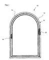
- FIG. 1 shows a top view of an arched window 10, consisting of a frame 12, which is fixed with a masonry, not shown, is connected, and one Casement 14, which rotates relative to the frame 12 or is tiltable. Inside the casement a drive rod fitting 16 is arranged, which by the Operating handle 18 is driven.
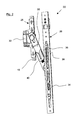
- FIG. 2 shows a spatial view of an opening device 20.
- the display device 20 is for use on the hinge side, i.e. on the control handle 18 opposite side designed, in Fig. 1 only the position 22 of the opening device 20 below of the arch 24 is recognizable.
- the representations 2 corresponds to the position of the opening device 20 in a tilted wing position.
- the opening device 20 consists of a first fitting module 26, a second fitting module 28 and a Extension arm arranged between the fitting modules 30.
- the extension arm 30 is on the fitting modules 26, 28 each rotatably supported via a hinge pin, whereby the hinge pin with an associated with the fitting module 28 Pivot arm 32 is connected.
- the first fitting module 26 has a faceplate 34, which can be screwed directly to the frame 12, and one with longitudinal movement relative to this Push rod 36.
- the push rod 36 is connected to one in FIG. 3 shown locking pin 38 for closing the Display device 20 provided. Thereby the Locking pin 38 along the faceplate longitudinal axis is displaceable with the push rod 36 for Closing the opening device 20 in on the opening arm 30 arranged locking pin receptacle 40 and blocked thus the mobility of the extension arm.
- the push rod 36 is driven as in FIG. 3 shown, starting from the connecting rod fitting 16 through a transmission element 42.
- This transmission element 42 consists of a rod-like base body 44 as well as first and second connection tabs at the ends 46, 48.
- These connecting lugs 46, 48 are with connecting means 50, 52 connectable, which is a mushroom-like Contour with a cylindrical shaft area and a have plate-like head area.
- the connection means either screwable with the espagnolette fitting respectively connected to the push rod, or it can have appropriate Connection lugs and corresponding recess areas by turning it slightly.
- the transmission element is in the closed state of the window 42 parallel to the push rod 36.
- rotated open state of the window is recognizable, that the transmission element 42 for bridging the distance slightly increased by the rotation between the connection means 50, 52 is slightly inclined.
- the associated slight switching differential, which is the push rod adjusts is within the tolerance range.
- To ensure the mobility is at least one of the base bodies 44 opposite the connecting lugs 46, 48 about the longitudinal axis of the base body rotatably mounted.
- the transmission element ensures through the constant connection between the Espagnolette fitting and the push rod that light Movements of the espagnolette fitting in the tilt or turn open position Condition does not cause problems with the following one Closing the window with regard to the active connection between the connecting rod and the push rod being able to lead.
Landscapes
- Engineering & Computer Science (AREA)
- Mechanical Engineering (AREA)
- Wing Frames And Configurations (AREA)
- Power-Operated Mechanisms For Wings (AREA)
- Hinges (AREA)
- Supports Or Holders For Household Use (AREA)
- Freezers Or Refrigerated Showcases (AREA)
Abstract
Description
- Fig. 1
- eine Draufsicht auf ein Rundbogenfenster;
- Fig. 2
- eine räumliche Ansicht einer Ausstellvorrichtung im kippgeöffneten Zustand;
- Fig. 3
- eine räumliche Ansicht einer Ausstellvorrichtung im drehgeöffneten Zustand.
Claims (7)
- Ausstellvorrichtung für Fenster und/oder Türen, mit ersten (26) und zweiten (28), einem Blendrahmen (12) beziehungsweise einem Flügelrahmen (14) zugeordneten Beschlagmodulen (26, 28) und mit einem die Beschlagmodule (26, 28) verbindenden Ausstellarm (30), sowie mit einem flügelrahmenseitigen Treibstangenbeschlag (16), wobei das erste Beschlagmodul (26) eine Stulpschiene (34) und eine gegenüber dieser längsverschiebliche Schubstange (36) aufweist und dem Blendrahmen (12) zugeordnet ist, und wobei das zweite Beschlagmodul (28) dem Flügelrahmen (14) zugeordnet ist, und wobei die Schubstange (36) ein erstes Anschlussmittel (50) und der Treibstangebeschlag (16) ein zweites Anschlussmittel (52) aufweist, dadurch gekennzeichnet, dass die Anschlussmittel (50, 52) durch ein Übertragungselement (42) zur Bewegungsübertragung zwischen dem Treibstangenbeschlag (16) und der Schubstange (36) in jeder Relativstellung des Flügelrahmens (14) gegenüber dem Blendrahmen (12) verbunden sind, wobei die Anschlussmittel (50, 52) in Richtung der Schubstangenlängsachse versetzt angeordnet sind.
- Ausstellvorrichtung nach Anspruch 1, dadurch gekennzeichnet, dass der Versatz zwischen den Anschlussmitteln (50, 52) und die dazu korrespondierend ausgeführte Länge des verbindenden Übertragungselements (42) derart bemessen ist, dass die Schaltdifferenz der Schubstange (36) zwischen einer geschlossenen und einer dreh- oder kippgeöffneten Stellung des Flügelrahmens (14) gegenüber dem Blendrahmen (12) innerhalb der Schaltpositions-Toleranzbereiche der Schubstange (36) liegt.
- Ausstellvorrichtung nach Anspruch 1 oder 2, dadurch gekennzeichnet, dass das Übertragungselement (42) einen stangenartigen Grundkörper (44) und jeweils endseitig erste (46) und zweite (48) Anschlusslaschen aufweist, die mit den ersten (50) und zweiten (52) Anschlussmitteln verbindbar sind.
- Ausstellvorrichtung nach einem der vorhergehenden Ansprüche, dadurch gekennzeichnet, dass die ersten (50) und zweiten (52) Anschlussmittel eine pilzartige Kontur mit einem zylindrischen Schaftbereich und einem tellerartigen Kopfbereich aufweisen, und dass die ersten und zweiten Anschlusslaschen Aussparungsbereiche zur Aufnahme der Anschlussmittel aufweisen.
- Ausstellvorrichtung nach einem der vorhergehenden Ansprüche, dadurch gekennzeichnet, dass die Höhe des zylindrischen Schaftbereichs ein Mehrfaches der Dicke der Anschlusslaschen beträgt, und dass der Öffnungsdurchmesser der Aussparungsbereiche der Anschlusslaschen (46, 48) den Durchmesser des Schaftbereichs übersteigt, so dass ein Winkelversatz zwischen der Längsachse des Übertragungselements (42) und einer Richtung quer zur Längsachse des Schaftbereichs ermöglicht ist.
- Ausstellvorrichtung nach einem der vorhergehenden Ansprüche, dadurch gekennzeichnet, dass der tellerartige Kopfbereich der Anschlussmittel (50, 52) radial abragende Halteflügel (51) aufweist, und dass die Anschlusslaschen (46, 48) über mit diesen korrespondierend ausgeführte Anschlussaussparungen verfügen, wobei die Anschlusslaschen (46, 48) und die Halteflügel (51) in einer Montageposition zur Herstellung einer Verbindung zueinander orientiert sind und in einer Funktionsposition zur Herstellung einer formschlüssigen Verbindung gegeneinander um die Längsachse des Schaftbereichs verdreht sind.
- Ausstellvorrichtung nach Anspruch 1, dadurch gekennzeichnet, dass das Übertragungselement einen stangenartigen Grundkörper und jeweils endseitig erste und zweite Anschlusselemente aufweist, die mit den ersten und zweiten Anschlussmitteln verbindbar sind, wobei die Anschlussmittel und Anschlusselemente als Kugelgelenke mit einer Gelenkkugel und einer Kugelpfanne zur Aufnahme der Gelenkkugel ausgeführt sind.
Applications Claiming Priority (2)
| Application Number | Priority Date | Filing Date | Title |
|---|---|---|---|
| DE10300198A DE10300198A1 (de) | 2003-01-08 | 2003-01-08 | Ausstellvorrichtung für Fenster und/oder Türen |
| DE10300198 | 2003-01-08 |
Publications (2)
| Publication Number | Publication Date |
|---|---|
| EP1437470A1 true EP1437470A1 (de) | 2004-07-14 |
| EP1437470B1 EP1437470B1 (de) | 2005-08-03 |
Family
ID=32478156
Family Applications (1)
| Application Number | Title | Priority Date | Filing Date |
|---|---|---|---|
| EP03104182A Expired - Lifetime EP1437470B1 (de) | 2003-01-08 | 2003-11-13 | Ausstellungsvorrichtung für Dreh-/Kippfenster und Dreh-/Kipptüren |
Country Status (5)
| Country | Link |
|---|---|
| EP (1) | EP1437470B1 (de) |
| AT (1) | ATE301230T1 (de) |
| DE (2) | DE10300198A1 (de) |
| ES (1) | ES2247487T3 (de) |
| PL (1) | PL364337A1 (de) |
Cited By (1)
| Publication number | Priority date | Publication date | Assignee | Title |
|---|---|---|---|---|
| CN106837031A (zh) * | 2017-03-20 | 2017-06-13 | 广东合和建筑五金制品有限公司 | 平开窗铰链 |
Citations (3)
| Publication number | Priority date | Publication date | Assignee | Title |
|---|---|---|---|---|
| CH208308A (de) * | 1939-02-18 | 1940-01-31 | Strasser Emil | Fenster. |
| DE3203320A1 (de) * | 1982-02-01 | 1983-09-22 | Fa. Aug. Winkhaus, 4404 Telgte | Drehkippfenster |
| DE19826051A1 (de) * | 1998-06-12 | 1999-12-16 | Winkhaus Fa August | Ausstellvorrichtung eines Drehkippflügel-Beschlags eines Fensters |
Family Cites Families (1)
| Publication number | Priority date | Publication date | Assignee | Title |
|---|---|---|---|---|
| DE1244014B (de) * | 1961-07-25 | 1967-07-06 | Wilhelm Weber | Betaetigungsvorrichtung fuer einen kipp- und schwenkbaren Fensterfluegel |
-
2003
- 2003-01-08 DE DE10300198A patent/DE10300198A1/de not_active Withdrawn
- 2003-11-13 DE DE50300902T patent/DE50300902D1/de not_active Expired - Lifetime
- 2003-11-13 EP EP03104182A patent/EP1437470B1/de not_active Expired - Lifetime
- 2003-11-13 ES ES03104182T patent/ES2247487T3/es not_active Expired - Lifetime
- 2003-11-13 AT AT03104182T patent/ATE301230T1/de active
-
2004
- 2004-01-08 PL PL04364337A patent/PL364337A1/xx not_active IP Right Cessation
Patent Citations (3)
| Publication number | Priority date | Publication date | Assignee | Title |
|---|---|---|---|---|
| CH208308A (de) * | 1939-02-18 | 1940-01-31 | Strasser Emil | Fenster. |
| DE3203320A1 (de) * | 1982-02-01 | 1983-09-22 | Fa. Aug. Winkhaus, 4404 Telgte | Drehkippfenster |
| DE19826051A1 (de) * | 1998-06-12 | 1999-12-16 | Winkhaus Fa August | Ausstellvorrichtung eines Drehkippflügel-Beschlags eines Fensters |
Cited By (1)
| Publication number | Priority date | Publication date | Assignee | Title |
|---|---|---|---|---|
| CN106837031A (zh) * | 2017-03-20 | 2017-06-13 | 广东合和建筑五金制品有限公司 | 平开窗铰链 |
Also Published As
| Publication number | Publication date |
|---|---|
| ATE301230T1 (de) | 2005-08-15 |
| PL364337A1 (en) | 2004-07-12 |
| EP1437470B1 (de) | 2005-08-03 |
| DE10300198A1 (de) | 2004-07-22 |
| ES2247487T3 (es) | 2006-03-01 |
| DE50300902D1 (de) | 2005-09-08 |
Similar Documents
| Publication | Publication Date | Title |
|---|---|---|
| EP1370742B1 (de) | Fenster-oder türaufbau | |
| EP1836367A1 (de) | Dreh-/kippfenster mit elektromotorischem antrieb mit schubkette | |
| EP0515931B1 (de) | Drehkippbeschlag | |
| DE68903724T2 (de) | Beschlag fuer tuer, fenster oder dergleichen. | |
| EP0265606B1 (de) | Scharniergelenk für fenster, Türen od.dgl. | |
| WO2008034652A1 (de) | Motorischer antrieb | |
| DE2451556A1 (de) | Feststellvorrichtung zur oeffnungsbegrenzung von kipp- und klappfluegeln, insbesondere kipp-schwenkfluegeln, an fenstern, tueren o.dgl. | |
| EP0908585B1 (de) | Beschlag mit einer verriegelbaren Handhabe für Fenster, Türen oder dergleichen | |
| EP1437470B1 (de) | Ausstellungsvorrichtung für Dreh-/Kippfenster und Dreh-/Kipptüren | |
| DE3619682C2 (de) | ||
| EP1223287B1 (de) | Montagefreundliche Scherenanordnung mit Zusatzfunktion | |
| DE2658626A1 (de) | Dreh-kipp-beschlag | |
| EP1200698B1 (de) | Öffnungsbegrenzendes beschlagteil | |
| EP1422372B1 (de) | Fenster oder Tür | |
| DE19933576A1 (de) | Beschlag für Fenster oder Türen | |
| WO2008119451A1 (de) | Beschlag für ein fenster, eine tür oder dergleichen | |
| EP0704593B1 (de) | Dreh-Beschlag oder Dreh-Kipp-Beschlag von Fenster, Türen oder dergleichen mit verrastbarem Exzenterteil zum Einstellen einer horizontalen Falzluft und/oder eines Flügelanpressdrucks zwischen Festrahmen und/oder Flügelrahmen | |
| EP0450626B1 (de) | Zweiteiliges Scharnier für eine Klappe vorzugsweise an einem Möbelteil | |
| WO1997026432A1 (de) | Drehkipp-beschlag für fenster, türen oder dergleichen mit drehlager-betätigungseinrichtung | |
| EP3696357B1 (de) | Zur verdeckten anordnung vorgesehenes ecklager | |
| EP3203004B1 (de) | Scherenlager eines dreh-kipp-beschlages | |
| EP1347137B1 (de) | Austellvorrichtung für Drehkippfenster oder Drehkipptüren | |
| DE3935420C2 (de) | Dreh-Kipp-Beschlag für Fenster oder Türen | |
| EP0790380A1 (de) | Eckscharnier, insbesondere für Drehkipp-Ecklager für Fenster und Türen od. dgl. | |
| WO2006131447A1 (de) | Beschlag |
Legal Events
| Date | Code | Title | Description |
|---|---|---|---|
| PUAI | Public reference made under article 153(3) epc to a published international application that has entered the european phase |
Free format text: ORIGINAL CODE: 0009012 |
|
| AK | Designated contracting states |
Kind code of ref document: A1 Designated state(s): AT BE BG CH CY CZ DE DK EE ES FI FR GB GR HU IE IT LI LU MC NL PT RO SE SI SK TR |
|
| AX | Request for extension of the european patent |
Extension state: AL LT LV MK |
|
| 17P | Request for examination filed |
Effective date: 20041207 |
|
| GRAP | Despatch of communication of intention to grant a patent |
Free format text: ORIGINAL CODE: EPIDOSNIGR1 |
|
| AKX | Designation fees paid |
Designated state(s): AT BE BG CH CY CZ DE DK EE ES FI FR GB GR HU IE IT LI LU MC NL PT RO SE SI SK TR |
|
| GRAS | Grant fee paid |
Free format text: ORIGINAL CODE: EPIDOSNIGR3 |
|
| GRAA | (expected) grant |
Free format text: ORIGINAL CODE: 0009210 |
|
| AK | Designated contracting states |
Kind code of ref document: B1 Designated state(s): AT BE BG CH CY CZ DE DK EE ES FI FR GB GR HU IE IT LI LU MC NL PT RO SE SI SK TR |
|
| PG25 | Lapsed in a contracting state [announced via postgrant information from national office to epo] |
Ref country code: CZ Free format text: LAPSE BECAUSE OF FAILURE TO SUBMIT A TRANSLATION OF THE DESCRIPTION OR TO PAY THE FEE WITHIN THE PRESCRIBED TIME-LIMIT Effective date: 20050803 Ref country code: FI Free format text: LAPSE BECAUSE OF FAILURE TO SUBMIT A TRANSLATION OF THE DESCRIPTION OR TO PAY THE FEE WITHIN THE PRESCRIBED TIME-LIMIT Effective date: 20050803 Ref country code: EE Free format text: LAPSE BECAUSE OF FAILURE TO SUBMIT A TRANSLATION OF THE DESCRIPTION OR TO PAY THE FEE WITHIN THE PRESCRIBED TIME-LIMIT Effective date: 20050803 Ref country code: NL Free format text: LAPSE BECAUSE OF FAILURE TO SUBMIT A TRANSLATION OF THE DESCRIPTION OR TO PAY THE FEE WITHIN THE PRESCRIBED TIME-LIMIT Effective date: 20050803 Ref country code: IE Free format text: LAPSE BECAUSE OF FAILURE TO SUBMIT A TRANSLATION OF THE DESCRIPTION OR TO PAY THE FEE WITHIN THE PRESCRIBED TIME-LIMIT Effective date: 20050803 Ref country code: SK Free format text: LAPSE BECAUSE OF FAILURE TO SUBMIT A TRANSLATION OF THE DESCRIPTION OR TO PAY THE FEE WITHIN THE PRESCRIBED TIME-LIMIT Effective date: 20050803 Ref country code: SI Free format text: LAPSE BECAUSE OF FAILURE TO SUBMIT A TRANSLATION OF THE DESCRIPTION OR TO PAY THE FEE WITHIN THE PRESCRIBED TIME-LIMIT Effective date: 20050803 Ref country code: RO Free format text: LAPSE BECAUSE OF FAILURE TO SUBMIT A TRANSLATION OF THE DESCRIPTION OR TO PAY THE FEE WITHIN THE PRESCRIBED TIME-LIMIT Effective date: 20050803 Ref country code: GB Free format text: LAPSE BECAUSE OF FAILURE TO SUBMIT A TRANSLATION OF THE DESCRIPTION OR TO PAY THE FEE WITHIN THE PRESCRIBED TIME-LIMIT Effective date: 20050803 |
|
| REG | Reference to a national code |
Ref country code: GB Ref legal event code: FG4D Free format text: NOT ENGLISH |
|
| REG | Reference to a national code |
Ref country code: CH Ref legal event code: EP |
|
| REG | Reference to a national code |
Ref country code: IE Ref legal event code: FG4D Free format text: LANGUAGE OF EP DOCUMENT: GERMAN |
|
| REF | Corresponds to: |
Ref document number: 50300902 Country of ref document: DE Date of ref document: 20050908 Kind code of ref document: P |
|
| PG25 | Lapsed in a contracting state [announced via postgrant information from national office to epo] |
Ref country code: DK Free format text: LAPSE BECAUSE OF FAILURE TO SUBMIT A TRANSLATION OF THE DESCRIPTION OR TO PAY THE FEE WITHIN THE PRESCRIBED TIME-LIMIT Effective date: 20051103 Ref country code: SE Free format text: LAPSE BECAUSE OF FAILURE TO SUBMIT A TRANSLATION OF THE DESCRIPTION OR TO PAY THE FEE WITHIN THE PRESCRIBED TIME-LIMIT Effective date: 20051103 Ref country code: GR Free format text: LAPSE BECAUSE OF FAILURE TO SUBMIT A TRANSLATION OF THE DESCRIPTION OR TO PAY THE FEE WITHIN THE PRESCRIBED TIME-LIMIT Effective date: 20051103 Ref country code: BG Free format text: LAPSE BECAUSE OF FAILURE TO SUBMIT A TRANSLATION OF THE DESCRIPTION OR TO PAY THE FEE WITHIN THE PRESCRIBED TIME-LIMIT Effective date: 20051103 |
|
| PG25 | Lapsed in a contracting state [announced via postgrant information from national office to epo] |
Ref country code: CY Free format text: LAPSE BECAUSE OF FAILURE TO SUBMIT A TRANSLATION OF THE DESCRIPTION OR TO PAY THE FEE WITHIN THE PRESCRIBED TIME-LIMIT Effective date: 20051113 |
|
| PG25 | Lapsed in a contracting state [announced via postgrant information from national office to epo] |
Ref country code: BE Free format text: LAPSE BECAUSE OF NON-PAYMENT OF DUE FEES Effective date: 20051130 Ref country code: LU Free format text: LAPSE BECAUSE OF NON-PAYMENT OF DUE FEES Effective date: 20051130 Ref country code: MC Free format text: LAPSE BECAUSE OF NON-PAYMENT OF DUE FEES Effective date: 20051130 |
|
| PG25 | Lapsed in a contracting state [announced via postgrant information from national office to epo] |
Ref country code: PT Free format text: LAPSE BECAUSE OF FAILURE TO SUBMIT A TRANSLATION OF THE DESCRIPTION OR TO PAY THE FEE WITHIN THE PRESCRIBED TIME-LIMIT Effective date: 20060103 |
|
| NLV1 | Nl: lapsed or annulled due to failure to fulfill the requirements of art. 29p and 29m of the patents act | ||
| PG25 | Lapsed in a contracting state [announced via postgrant information from national office to epo] |
Ref country code: HU Free format text: LAPSE BECAUSE OF FAILURE TO SUBMIT A TRANSLATION OF THE DESCRIPTION OR TO PAY THE FEE WITHIN THE PRESCRIBED TIME-LIMIT Effective date: 20060204 |
|
| GBV | Gb: ep patent (uk) treated as always having been void in accordance with gb section 77(7)/1977 [no translation filed] |
Effective date: 20050803 |
|
| REG | Reference to a national code |
Ref country code: ES Ref legal event code: FG2A Ref document number: 2247487 Country of ref document: ES Kind code of ref document: T3 |
|
| REG | Reference to a national code |
Ref country code: IE Ref legal event code: FD4D |
|
| ET | Fr: translation filed | ||
| PLBE | No opposition filed within time limit |
Free format text: ORIGINAL CODE: 0009261 |
|
| STAA | Information on the status of an ep patent application or granted ep patent |
Free format text: STATUS: NO OPPOSITION FILED WITHIN TIME LIMIT |
|
| 26N | No opposition filed |
Effective date: 20060504 |
|
| BERE | Be: lapsed |
Owner name: AUG. WINKHAUS G.M.B.H. & CO. KG Effective date: 20051130 |
|
| PG25 | Lapsed in a contracting state [announced via postgrant information from national office to epo] |
Ref country code: CH Free format text: LAPSE BECAUSE OF NON-PAYMENT OF DUE FEES Effective date: 20071130 Ref country code: LI Free format text: LAPSE BECAUSE OF NON-PAYMENT OF DUE FEES Effective date: 20071130 |
|
| REG | Reference to a national code |
Ref country code: CH Ref legal event code: PL |
|
| PGFP | Annual fee paid to national office [announced via postgrant information from national office to epo] |
Ref country code: FR Payment date: 20101209 Year of fee payment: 8 |
|
| PGFP | Annual fee paid to national office [announced via postgrant information from national office to epo] |
Ref country code: IT Payment date: 20101120 Year of fee payment: 8 Ref country code: TR Payment date: 20101115 Year of fee payment: 8 |
|
| PGFP | Annual fee paid to national office [announced via postgrant information from national office to epo] |
Ref country code: ES Payment date: 20101125 Year of fee payment: 8 |
|
| REG | Reference to a national code |
Ref country code: FR Ref legal event code: ST Effective date: 20120731 |
|
| PG25 | Lapsed in a contracting state [announced via postgrant information from national office to epo] |
Ref country code: IT Free format text: LAPSE BECAUSE OF NON-PAYMENT OF DUE FEES Effective date: 20111113 |
|
| PG25 | Lapsed in a contracting state [announced via postgrant information from national office to epo] |
Ref country code: FR Free format text: LAPSE BECAUSE OF NON-PAYMENT OF DUE FEES Effective date: 20111130 |
|
| REG | Reference to a national code |
Ref country code: ES Ref legal event code: FD2A Effective date: 20130606 |
|
| PG25 | Lapsed in a contracting state [announced via postgrant information from national office to epo] |
Ref country code: ES Free format text: LAPSE BECAUSE OF NON-PAYMENT OF DUE FEES Effective date: 20111114 |
|
| PG25 | Lapsed in a contracting state [announced via postgrant information from national office to epo] |
Ref country code: TR Free format text: LAPSE BECAUSE OF NON-PAYMENT OF DUE FEES Effective date: 20111113 |
|
| PGFP | Annual fee paid to national office [announced via postgrant information from national office to epo] |
Ref country code: AT Payment date: 20151125 Year of fee payment: 13 |
|
| PGFP | Annual fee paid to national office [announced via postgrant information from national office to epo] |
Ref country code: DE Payment date: 20170131 Year of fee payment: 14 |
|
| REG | Reference to a national code |
Ref country code: AT Ref legal event code: MM01 Ref document number: 301230 Country of ref document: AT Kind code of ref document: T Effective date: 20161113 |
|
| PG25 | Lapsed in a contracting state [announced via postgrant information from national office to epo] |
Ref country code: AT Free format text: LAPSE BECAUSE OF NON-PAYMENT OF DUE FEES Effective date: 20161113 |
|
| REG | Reference to a national code |
Ref country code: DE Ref legal event code: R119 Ref document number: 50300902 Country of ref document: DE |
|
| PG25 | Lapsed in a contracting state [announced via postgrant information from national office to epo] |
Ref country code: DE Free format text: LAPSE BECAUSE OF NON-PAYMENT OF DUE FEES Effective date: 20180602 |