EP1429886B1 - Synchronised tubular friction welding arrangement and method - Google Patents
Synchronised tubular friction welding arrangement and method Download PDFInfo
- Publication number
- EP1429886B1 EP1429886B1 EP02766042A EP02766042A EP1429886B1 EP 1429886 B1 EP1429886 B1 EP 1429886B1 EP 02766042 A EP02766042 A EP 02766042A EP 02766042 A EP02766042 A EP 02766042A EP 1429886 B1 EP1429886 B1 EP 1429886B1
- Authority
- EP
- European Patent Office
- Prior art keywords
- arrangement
- shaft
- chuck assembly
- jaws
- cylindrical shaft
- Prior art date
- Legal status (The legal status is an assumption and is not a legal conclusion. Google has not performed a legal analysis and makes no representation as to the accuracy of the status listed.)
- Expired - Lifetime
Links
Images


Classifications
-
- B—PERFORMING OPERATIONS; TRANSPORTING
- B21—MECHANICAL METAL-WORKING WITHOUT ESSENTIALLY REMOVING MATERIAL; PUNCHING METAL
- B21D—WORKING OR PROCESSING OF SHEET METAL OR METAL TUBES, RODS OR PROFILES WITHOUT ESSENTIALLY REMOVING MATERIAL; PUNCHING METAL
- B21D3/00—Straightening or restoring form of metal rods, metal tubes, metal profiles, or specific articles made therefrom, whether or not in combination with sheet metal parts
- B21D3/10—Straightening or restoring form of metal rods, metal tubes, metal profiles, or specific articles made therefrom, whether or not in combination with sheet metal parts between rams and anvils or abutments
-
- B—PERFORMING OPERATIONS; TRANSPORTING
- B23—MACHINE TOOLS; METAL-WORKING NOT OTHERWISE PROVIDED FOR
- B23K—SOLDERING OR UNSOLDERING; WELDING; CLADDING OR PLATING BY SOLDERING OR WELDING; CUTTING BY APPLYING HEAT LOCALLY, e.g. FLAME CUTTING; WORKING BY LASER BEAM
- B23K20/00—Non-electric welding by applying impact or other pressure, with or without the application of heat, e.g. cladding or plating
- B23K20/12—Non-electric welding by applying impact or other pressure, with or without the application of heat, e.g. cladding or plating the heat being generated by friction; Friction welding
- B23K20/121—Control circuits therefor
-
- B—PERFORMING OPERATIONS; TRANSPORTING
- B23—MACHINE TOOLS; METAL-WORKING NOT OTHERWISE PROVIDED FOR
- B23K—SOLDERING OR UNSOLDERING; WELDING; CLADDING OR PLATING BY SOLDERING OR WELDING; CUTTING BY APPLYING HEAT LOCALLY, e.g. FLAME CUTTING; WORKING BY LASER BEAM
- B23K20/00—Non-electric welding by applying impact or other pressure, with or without the application of heat, e.g. cladding or plating
- B23K20/12—Non-electric welding by applying impact or other pressure, with or without the application of heat, e.g. cladding or plating the heat being generated by friction; Friction welding
- B23K20/129—Non-electric welding by applying impact or other pressure, with or without the application of heat, e.g. cladding or plating the heat being generated by friction; Friction welding specially adapted for particular articles or workpieces
-
- B—PERFORMING OPERATIONS; TRANSPORTING
- B23—MACHINE TOOLS; METAL-WORKING NOT OTHERWISE PROVIDED FOR
- B23K—SOLDERING OR UNSOLDERING; WELDING; CLADDING OR PLATING BY SOLDERING OR WELDING; CUTTING BY APPLYING HEAT LOCALLY, e.g. FLAME CUTTING; WORKING BY LASER BEAM
- B23K37/00—Auxiliary devices or processes, not specially adapted for a procedure covered by only one of the other main groups of this subclass
- B23K37/04—Auxiliary devices or processes, not specially adapted for a procedure covered by only one of the other main groups of this subclass for holding or positioning work
- B23K37/053—Auxiliary devices or processes, not specially adapted for a procedure covered by only one of the other main groups of this subclass for holding or positioning work aligning cylindrical work; Clamping devices therefor
- B23K37/0533—External pipe alignment clamps
-
- F—MECHANICAL ENGINEERING; LIGHTING; HEATING; WEAPONS; BLASTING
- F16—ENGINEERING ELEMENTS AND UNITS; GENERAL MEASURES FOR PRODUCING AND MAINTAINING EFFECTIVE FUNCTIONING OF MACHINES OR INSTALLATIONS; THERMAL INSULATION IN GENERAL
- F16C—SHAFTS; FLEXIBLE SHAFTS; ELEMENTS OR CRANKSHAFT MECHANISMS; ROTARY BODIES OTHER THAN GEARING ELEMENTS; BEARINGS
- F16C3/00—Shafts; Axles; Cranks; Eccentrics
- F16C3/02—Shafts; Axles
-
- F—MECHANICAL ENGINEERING; LIGHTING; HEATING; WEAPONS; BLASTING
- F16—ENGINEERING ELEMENTS AND UNITS; GENERAL MEASURES FOR PRODUCING AND MAINTAINING EFFECTIVE FUNCTIONING OF MACHINES OR INSTALLATIONS; THERMAL INSULATION IN GENERAL
- F16D—COUPLINGS FOR TRANSMITTING ROTATION; CLUTCHES; BRAKES
- F16D3/00—Yielding couplings, i.e. with means permitting movement between the connected parts during the drive
- F16D3/16—Universal joints in which flexibility is produced by means of pivots or sliding or rolling connecting parts
- F16D3/26—Hooke's joints or other joints with an equivalent intermediate member to which each coupling part is pivotally or slidably connected
- F16D3/38—Hooke's joints or other joints with an equivalent intermediate member to which each coupling part is pivotally or slidably connected with a single intermediate member with trunnions or bearings arranged on two axes perpendicular to one another
- F16D3/40—Hooke's joints or other joints with an equivalent intermediate member to which each coupling part is pivotally or slidably connected with a single intermediate member with trunnions or bearings arranged on two axes perpendicular to one another with intermediate member provided with two pairs of outwardly-directed trunnions on intersecting axes
- F16D3/405—Apparatus for assembling or dismantling
-
- B—PERFORMING OPERATIONS; TRANSPORTING
- B23—MACHINE TOOLS; METAL-WORKING NOT OTHERWISE PROVIDED FOR
- B23K—SOLDERING OR UNSOLDERING; WELDING; CLADDING OR PLATING BY SOLDERING OR WELDING; CUTTING BY APPLYING HEAT LOCALLY, e.g. FLAME CUTTING; WORKING BY LASER BEAM
- B23K2101/00—Articles made by soldering, welding or cutting
- B23K2101/005—Camshafts
-
- B—PERFORMING OPERATIONS; TRANSPORTING
- B23—MACHINE TOOLS; METAL-WORKING NOT OTHERWISE PROVIDED FOR
- B23K—SOLDERING OR UNSOLDERING; WELDING; CLADDING OR PLATING BY SOLDERING OR WELDING; CUTTING BY APPLYING HEAT LOCALLY, e.g. FLAME CUTTING; WORKING BY LASER BEAM
- B23K2101/00—Articles made by soldering, welding or cutting
- B23K2101/006—Vehicles
-
- F—MECHANICAL ENGINEERING; LIGHTING; HEATING; WEAPONS; BLASTING
- F16—ENGINEERING ELEMENTS AND UNITS; GENERAL MEASURES FOR PRODUCING AND MAINTAINING EFFECTIVE FUNCTIONING OF MACHINES OR INSTALLATIONS; THERMAL INSULATION IN GENERAL
- F16C—SHAFTS; FLEXIBLE SHAFTS; ELEMENTS OR CRANKSHAFT MECHANISMS; ROTARY BODIES OTHER THAN GEARING ELEMENTS; BEARINGS
- F16C2226/00—Joining parts; Fastening; Assembling or mounting parts
- F16C2226/30—Material joints
- F16C2226/36—Material joints by welding
-
- F—MECHANICAL ENGINEERING; LIGHTING; HEATING; WEAPONS; BLASTING
- F16—ENGINEERING ELEMENTS AND UNITS; GENERAL MEASURES FOR PRODUCING AND MAINTAINING EFFECTIVE FUNCTIONING OF MACHINES OR INSTALLATIONS; THERMAL INSULATION IN GENERAL
- F16D—COUPLINGS FOR TRANSMITTING ROTATION; CLUTCHES; BRAKES
- F16D2250/00—Manufacturing; Assembly
Definitions
- This invention relates generally to an arrangement and a method for welding first and second shaft termination elements at respective first and second ends of a cylindral shaft and more particularly, to a welding arrangement that will weld tubular products that require low cycle time, minimal misalignment, and near perfect radial alignment of the welded ends.
- magna pulse and magna arc methods are used in the construction of drive shafts and other tubular products. Again, typically one side of the tubular product is completed at a time. This causes set up problems that limit the ability to maintain radial alignment and verification of the quality of the weld is difficult to accomplish. Double ended magna arc or pulse welders are complex, difficult to repair and maintain, and expensive. In addition, They also require that extremely close tolerances be in squareness, cleanliness, and flatness of the components prior to and during the weld process to maintain a proper arc gap. This is difficult to accomplish and maintain in a production environment.
- JP-A-11 077 338 discloses an arrangement for friction butt welding first and second elongate elements in alignment with a predetermined axis, the arrangement comrpising:
- said first chuck assembly is rotated by said rotary drive while said second chuck assembly, which does not rotate, is translated towards said first chuck assembly to press the second ends of the two elongate elements together while the first elongate element rotates relative to the second elongate element (which does not rotate) to produce a friction butt weld at said second end.
- This arrangement is not capable of simultaneously welding respective shaft termination elements to the ends of a cylindrical shaft.
- US-A-4 060 190 which is considered to represent the most relevant state of the art, discloses an apparatus and method for welding end parts to a central shaft.
- This application discloses the use of only one chuck assembly for clamping the central part at the two extremities, the clamping means being rotated all together through a pinion.
- This central clamp is therefore fixedly positioned at the centre part of the welding machine.
- the two end parts are fixed in end part receivers which are translated towards the central part for welding through the use of drive arrangements, as the central part is rotated.
- an object of this invention to provide a system wherein the weld ends of a tubular assembly can be welded simultaneously in a simple, cost-effective and production robust manner.
- the invention which provides a n arrangement for welding first and second shaft termination elements at respective first and second ends of a cylindrical shaft, and in alignment with a predetermined axis, the arrangement comprising:
- the invention also includes a method of welding first and second shaft termination elements at respective first and second ends of a cylindrical shaft, and in alignment with a predetermined axis, the method comprising the steps of:
- a shaft receiver drive arrangement for translating the shaft receiver between a first shaft receiver position where the cylindrical shaft is supported by the shaft receiver at a transaxial location that is substantially in axial alignment with the first chuck assembly, and a second shaft receiver position distal from the first shaft receiver position.
- the cylindrical shaft is axially displaceable with respect to the shaft receiver, and the chuck assembly drive includes a pneumatic drive.
- the rotatory drive urges the first chuck assembly to rotate at approximately between 600 to 4000 rpm.
- the plurality of first gripping elements of the first chuck assembly includes, in certain embodiments, first and second sets of jaws.
- the first set of jaws is arranged to communicate with the cylindrical shaft prior to the second set of jaws, and may be regulated by mechanical cam.
- the first set of jaws may additionally include a precision alignment arrangement for locking the cylindrical shaft at a predetermined axial location.
- Such a precision alignment arrangement includes a plurality of angulated guideways associated with respective jaws of the first set of jaws, the angulated guideways having a precise angular orientation with respect to one another.
- the plurality of angulated guideways are equiangularly distributed about the predetermined axis.
- the second set of jaws is provided, in certain embodiments, with a clamping arrangement for locking the cylindrical shaft at the predetermined axial location determined by the first set of jaws.
- the first and second sets of jaws are hydraulically actuated, whereby the second set of jaws is operated in response to a first hydraulic pressure applied to the first set of jaws exceeding a predetermined break-over first hydraulic pressure value.
- the break-over first hydraulic pressure has a magnitude sufficient to cause the first set of jaws to lock the cylindrical shaft at the predetermined axial location.
- the welding arrangements there is provided a non-rotating housing about which the first chuck assembly is rotated by the rotatory drive.
- the first chuck assembly is installed on a rotatable housing, and there is further provided a fluid delivery arrangement disposed at the interface of the non-rotating and the rotatable housings.
- the fluid delivery arrangement is provided with a first fluid channel system for supplying pressurized clamping fluid for causing the first chuck assembly to grip the cylindrical shaft and a second fluid channel system for supplying pressurized unclamping fluid for causing the first chuck assembly to release the cylindrical shaft.
- the second fluid channel system has a first fluid passageway at the interface of the non-rotating and the rotatable housings, and there is further provided a pressurized fluid supply port installed on the non-rotating housing. Additionally, there is provided a fluid drain port installed on the non-rotating housing.
- a bearing arrangement is interposed between the non-rotating and the rotatable housings, and there is further provided a fluid seal for limiting flow of a pressurized fluid through the bearing arrangement.
- first and second installation drive arrangements urge the first and second shaft termination elements, respectively, axially toward the cylindrical shaft as the cylindrical shaft is rotated by applying respective first and second axial forces in respective axially opposing directions.
- the respective first and second axial forces each are exerted at respective magnitudes of axial force for respective determined periods of time.
- At least one of the first and second axial forces is applied at a plurality of magnitudes of axial force for respective determined sequential periods of time.
- at least one of the first and second axial forces is applied in response to a distance of axial displacement resulting from the application of the respective first and second axial forces.
- the respective determined sequential periods of time correspond to engagement phases of an installation of the first shaft termination element.
- the engagement phases of the installation of the first shaft termination element comprise a heating phase and a forging phase.
- the first installation drive arrangement is operated to apply approximately between 1.1 to 4.4 KN (250 to 1000 pounds) of axial force for a duration of approximately between 1.5 and 3 seconds during the heating phase, and applies approximately between 11.1 to 53.4 KN (2500 to 12000 pounds) of axial force for a duration of approximately between 2 and 5 seconds during the forging phase.
- the further phase of scrubbing the first shaft termination element against the first end of the cylindrical shaft Prior to performing the heating and forging phases there is provided in one embodiment the further phase of scrubbing the first shaft termination element against the first end of the cylindrical shaft.
- the first installation drive arrangement is operated to apply approximately between 0.6 to 1.5 KN (50 to 350 pounds) of axial force for a duration of approximately between 0.5 and 2 seconds during the further phase of scrubbing.
- At least one of the first and second axial forces is applied in response to a temperature resulting from the application of the respective first and second axial forces, the temperature being controlled in response to the modulation of the weld force between tube ends and the respective shaft termination element while rotating the tube.
- the cylindrical shaft is rotated at a fixed preselected speed that is determined in response to the diameter of the cylindrical shaft. In some embodiments, the cylindrical shaft is rotated at a speed that achieves a determined rotational surface speed of the cylindrical shaft.
- the further may include the additional steps of:
- the step of first actuating includes the further steps of:
- the step of first actuating includes the further step of second subset actuating a second subset of jaws, the step of second subset actuating being performed after the step of first subset actuating.
- the step of first actuating is performed in response to a step of applying an hydraulic pressure, and the step of second subset actuating is performed in response to the hydraulic pressure exceeding a predetermined hydraulic pressure magnitude.
- Fig. 1 is a simplified schematic representation of a synchronous welding system 100 constructed in accordance with the principles of the invention, as represented from above.
- a human operator 11 loads a drive shaft tube 15 onto a deployable drive shaft support that is designated generally as 17 that will be discussed in greater detail below in connection with Figs. 3B and 9.
- Human operator 11 may be replaced, in other embodiments of the invention, with a robotic delivery system (not shown).
- the human operator is shown in this figure to be holding a further drive shaft tube, designated herein as drive shaft tube 15'.
- Drive shaft tube 15' is in all respects substantially identical to drive shaft tube 15 that is shown to be already installed on deployable drive shaft support 17, and its corresponding portions are similarly designated, but with the addition of a prime (').
- Drive shaft tube 15 is shown to have a first portion 20 having a first diameter determined at a first datum line 21.
- the drive shaft tube also has a second portion 23 having a second diameter determined at a second datum line 24.
- Datum lines 21 and 24 are used as the reference for most dimensions of the drive shaft tube during manufacture thereof.
- the end to be achieved in the processing to be effected by synchronous welding system 100 on drive shaft tube 15 is the installation by friction welding of a first end piece 30, which in this embodiment of the invention is a constant velocity joint, onto the end of first portion 20, and the installation of a second end piece 32, which in this embodiment of the invention is a portion of a universal joint, onto the end of second portion 23.
- Such installation of the first and second end pieces is to be performed simultaneously while, in this specific illustrative embodiment of the invention, all of the elements are supported on a common axis, to achieve high radial and axial alignment as described herein.
- Synchronous welding system 100 is comprised of several major subsystems that include, in this specific illustrative embodiment of the invention, a base 40, a driven chuck assembly designated generally as 45, a translatable chuck assembly designated generally as 50.
- Driven chuck assembly 45 is installed on base 40 and has associated therewith a rotatory drive arrangement designated generally as 55.
- Rotatory drive arrangement 55 in this embodiment has an electric motor 56 that is mechanically coupled to driven chuck assembly 45 by a drive belt 57 that transfers rotatory energy from electric motor 56 to driven chuck assembly 45.
- a fixture in the form of a driven chuck assembly 45 and electric motor 56 maintain their position with respect to base 40 during all operations.
- translatable chuck assembly 50 is translatable in the direction of dual-head arrow 51 along base 40. Such translation of translatable chuck assembly 50 is effected by any known means, including pneumatic and/or hydraulic actuation (not shown). Finally, there is provided the aforementioned deployable drive shaft support 17, which as will be described is deployable to avoid interference with the translation of translatable chuck assembly 50.
- Fig. 1 additionally shows that a further first end piece 30' and a further second end piece 32' are shown to be pre-loaded in receptacles 60 and 61 of the respective chuck assemblies 45 and 50. More specifically, in this specific illustrative embodiment of the invention, further first end piece 30' is pre-installed in receptacle 60 which, as will be described below, clamps onto further first end piece 30' and transports same to the location of first end piece 30 after first end piece 30 has been installed onto drive shaft tube 15. Similarly, further second end piece 32' is pre-installed in receptacle 61, and also clamps onto further second end piece 32' and transports same to the location of second end piece 32 after second end piece 32 has been installed onto drive shaft tube 15.
- Fig. 2A is a simplified schematic front representation of synchronous welding system 100 of Fig. 1. Elements of structure that previously have been discussed are similarly designated.
- driven chuck assembly 45 has a chuck assembly 70 that is shown in this figure to have a plurality of chuck jaws 71 in an open condition.
- translatable chuck assembly 50 has a chuck assembly 75 that is shown in this figure to have a plurality of chuck jaws 76 in an open condition.
- the drive shaft tube is shown in this figure to be supported by deployable drive shaft support 17.
- the deployable drive shaft support is formed of a support platform 80 that is itself supported to be pivotable on hinged arms 81, pivotal deployment of deployable drive shaft support 17 being effected by actuation of an hydraulic cylinder 84.
- Fig. 2B is a simplified schematic side representation of the synchronous welding system of Fig. 2A, and shows the rotatory coupling between electric motor 56 and chuck assembly 70 via drive belt 57.
- chuck assembly 70 is shown to have a plurality of chuck jaws 71 distributed circumferentially therearound.
- an end representation of further first end piece 30' is shown in this figure to facilitate comprehension of its spatial relationship in the uninstalled position with respect to the rotating center of chuck assembly 70.
- Fig. 3A is a simplified schematic front representation of the synchronous welding system of Fig. 1 showing drive shaft tube 15 having been translated to the right so as to be within chuck assembly 70. Elements of structure that previously have been discussed are similarly designated.
- Chuck jaws 71 are shown to be closed on first portion 20 of drive shaft tube 15.
- chuck assembly 70 may have over 12 chuck jaws 71. Accuracy of the clamping is achieved by a sequential closure of the chuck jaws. More specifically, in this specific illustrative embodiment of the invention, three chuck jaws (not specifically designated) are first closed on first portion 20 of drive shaft tube 15.
- the three jaws are controlled in their operation by a cam plate (not specifically identified) that ensures that the three chuck jaws maintain radial equality as they translate radially toward, and communicate with first portion 20 of drive shaft tube 15.
- a cam plate not specifically identified
- the remaining chuck jaws are closed without disturbing the axial location of drive shaft tube 15 established during closure of the three cam-controlled chuck jaws.
- chuck jaws 71 are hydraulically actuated, and sequential operation of the closure of the chuck jaws is effected by hydraulic pressure break-over that results from the hydraulic pressure build-up that results from the engagement of the three cam-controlled chuck jaws.
- hydraulic pressure builds in the supply system (not shown).
- hydraulic fluid illustratively by operation of a pressure-responsive valve (not shown) is diverted to actuate selective ones or all of the remaining chuck jaws.
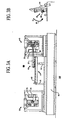
- Fig. 3B is a simplified schematic side representation of a portion of the deployable drive shaft support 17 portion of synchronous welding system 100 showing deployable drive shaft support 17 in a withdrawn position.
- extension of hydraulic cylinder 84 causes support platform 80 to be pivoted in the direction of arrow 86. Such pivotal withdrawal of support platform 80 is required to prevent collision with translatable chuck assembly 50 when it is translated along base 40 as described below.
- Fig. 4 is a simplified schematic front representation of synchronous welding system 100 wherein deployable drive shaft support 17 is in the condition of Fig. 3A. Elements of structure that previously have been discussed are similarly designated. Deployable drive shaft support 17 (not shown in this figure) has been withdrawn. As shown, chuck jaws 71 of chuck assembly 70 are shown in an engaged condition with first portion 20 of drive shaft tube 15. Translatable chuck assembly 50, however, is shown to have chuck jaws 76 of chuck assembly 75 to be in the open condition. Translatable chuck assembly 50 is therefore ready to be translated leftward, in the direction of arrow 88.
- Fig. 5 is a simplified schematic front representation of synchronous welding system 100 wherein translatable chuck assembly 50 has been translated leftward, and chuck jaws 76 of chuck assembly 75 are closed to communicate with second portion 23 of drive shaft tube 15.
- the closure of chuck jaws 76 is effected in accordance with the procedure described hereinabove in connection with the closure of chuck jaws 71 of chuck assembly 70. More specifically, three chuck jaws (not specifically designated) are first closed on first portion 23 of drive shaft tube 15.
- the three jaws are controlled in their operation by a cam plate (not specifically identified in this figure) that ensures that the three chuck jaws maintain radial equality as they translate radially toward, and communicate with first portion 23 of drive shaft tube 15.
- the cam plate is shown cross-sectionally in Fig. 11B.
- chuck jaws 71 and chuck jaws 76 being engaged with drive shaft tube 15 permits the rotatory motion that is applied to chuck assembly 70 by operation of electric motor 56 (not shown in this figure) and drive belt 57 to transmit via drive shaft tube 15 to chuck assembly 75.
- chuck assembly 70, drive shaft tube 15, and chuck jaws 76 rotate as a unit.
- hydraulic actuators 90 and 91 are shown to be drawn in so as to urge first end piece 30 and second end piece 32 axially in the directions of respective arrows 93 and 94.
- first end piece 30 and second end piece 32 are clamped so as not to be rotatable.
- first end piece 30, drive shaft tube 15, and second end piece 32 are maintained in precise axial alignment.
- the force applied in the directions of respective arrows 93 and 94 is not necessarily constant, and may be applied in stages. More specifically, in one specific illustrative embodiment of the invention, there is provided a first force stage where the end pieces are each merely scuffed against the rotating drive shaft tube 15 in order to square-off the mating surfaces. In a practical embodiment of the invention, this first stage, which may be termed a "scrub" stage, has a duration of approximately one (1) second. The axial force applied during this first stage may be on the order of several hundred pounds, where a pound force is approximately 4 ⁇ 5N. Then, in a second stage, additional axial force is applied to effect the heating to a level adequate to achieve welding.
- This second stage which may be termed a "heating” stage, may in one embodiment have a duration of approximately two (2) seconds.
- the axial force applied during this second stage may be approximately between four hundred and two thousand 1 ⁇ 8 - 8 ⁇ 9 KN (400-2000 pounds).
- the temperature during heat phase is monitored with commercially available equipment to insure that the weld temperature of each end of the tube and their respective yokes is correct to obtain a proper weld.
- Proper temperature is obtained, in a practical embodiment, by modulating the magnitude of the weld force between the tube ends and their respective yokes while rotating the tube at a fixed preselected speed.
- This method allows components of different diameters at each end to be welded successfully. It is to be noted that different diameters will have different surface speeds, and since the heat generated is a function of surface speed and the applicable coefficient of friction, the variation in the applied force will make up for the difference in the surface speed of each end of the tube.
- the coefficient of friction is constant for the same material, i.e., at both ends of same tube.
- a forging axial force is applied simultaneously to first end piece 3 0 and second end piece 32.
- the third stage may, in one embodiment of the invention have a duration of approximately three and one-half (3.5) seconds.
- the axial force applied during this third stage may be approximately 26.7 KN (approximately six thousand (6000) pounds). As stated, precise axial alignment is maintained between the components, ultimately resulting in an axially true drive shaft.
- the first is an open loop system where the thermal and force characteristics of the weld are only recorded and verified. This verification data is compared against predetermined acceptable weld criteria.
- the data may be derived from thermal sensors and pressure transducers (not shown).
- a linear displacement transducer may, in certain embodiments, be employed to ascertain the extent to which the axial dimension of the drive shaft is affected by the welding process.
- the second method involves monitoring of the distance per stage.
- the third and preferred method is the closed loop control of burn off, heat up, and forge force.
- the feedback pressure sensor is correlated to the forge force applied in the referenced third stage of the friction weld.
- the forge force is the primary control loop in the final stage of the friction weld.
- the force on the servo rams is the inner, cascaded control loop in the burn off (first stage) and heat up (second stage) portions of the weld process.
- the finished length, as measured by a linear gauge (not shown) is verified, but is not a primary control parameter.
- Fig. 6 is a simplified schematic front representation of synchronous welding system 100 in the condition of releasing of the axial force (in the direction of the arrows 100 and 101) arrangement with the drive shaft and the driven chuck in a disengaged condition. Elements of structure that previously have been discussed are similarly designated.
- hydraulic actuators 90 and 91 are in extended position, whereby the axial forging force on drive shaft tube 15 exerted via first end piece 30 and second end piece 32 has been released.
- chuck jaws 76 of chuck assembly 75 are opened, and therefore translatable chuck assembly 50 is now ready to be translated in the direction of arrow 101.
- Fig. 7 is a simplified schematic front representation of synchronous welding system 100 with translatable chuck assembly 50 having been restored to the left, and thereby is disengaged from drive shaft tube 15, which now forms a portion of a completed drive shaft. Elements of structure that previously have been discussed are similarly designated.
- deployable drive shaft support 17 is shown in the deployed condition ready to accept drive shaft tube 15 with first end piece 30 and second end piece 32 installed thereon.
- Fig. 8 is a simplified schematic side representation of deployable drive shaft support 17 in a deployed position for supporting drive shaft tube 15. As shown, hydraulic cylinder 84 is in a withdrawn condition, whereby support platform 80 is raised in the direction of arrow 105.
- chuck jaws 71 of chuck assembly 70 are in the open condition.
- drive shaft tube 15 with first end piece 30 can be axially removed from chuck assembly 70.
- Fig. 9 is a simplified schematic front representation of synchronous welding system 100 with drive shaft tube 15 with first end piece 30 and second end piece 32 installed thereon fully disengaged from driven chuck assembly 45 and translatable chuck assembly 50, and supported by deployable drive shaft support 17.
- the completed drive shaft can be removed from deployable drive shaft support 17 and replaced by drive shaft tube 15', illustratively by human operator 11 in Fig. 1, to commence welding of another drive shaft using drive shaft tube 15', further first end piece 30', and further second end piece 32'.
- Fig. 10 is a simplified schematic phantom representation of driven chuck assembly 45. Elements of structure that previously have been discussed are similarly designated.
- chuck assembly 70 is located as a subassembly of driven chuck assembly 45, and there is additionally provided an end piece carrier that is generally designated as 150.
- the end piece carrier is translatable in the directions of two-headed arrow 153.
- End piece carrier 150 is shown to have a receptacle 155 in which is deposited further first end piece 30' in anticipation of it being installed on further drive shaft tube 15' (not shown in this figure) of Fig. 1.
- the completed drive shaft is removed from deployable drive shaft support 17 by human operator 11, and further drive shaft tube 15' is installed thereon by the human operator.
- End piece carrier 150 is translated toward the left whereby further first end piece 30' is caused to be installed in a first central clamping station 160. Such translation is effected by actuation of hydraulic actuator 162, which urges end piece carrier 150 along tracks 165.
- First central clamping station 160 maintains the relocated further first end piece 30' in a clamped so as to be non-rotatable and axially co-located with further drive shaft tube 15' (not shown in this figure) during the friction welding process, which proceeds as described hereinabove with respect to the welding of first end piece 30 and drive shaft tube 15.
- a sensor 157 In controlling the operation of the translation of end piece carrier 150, its location is determined by a sensor 157 that is of the proximity type. Sensor 157 issues an electrical signal responsive to the proximity of sensor arm 158.
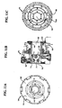
- Figs. 11A, 11B, and 11C are respective simplified schematic front, cross-sectional side, and back representations of chuck assembly 70. Elements of structure that previously have been discussed are similarly designated.
- chuck assembly 70 is provided with a housing 180 having a substantially planar forward surface 182 having a central aperture 185 therethrough. Radially inward of central aperture 185 are a plurality of chuck jaws 71. Twelve such chuck jaws are shown in this figure, and it can be seen in Fig. 11B that more than one row of jaws are employed in this specific illustrative embodiment of the invention.
- chuck jaws that are located proximal to cam plate 187 are designated as chuck jaws 71, and those that are disposed axially inward are designated chuck jaws 71'.
- Cam plate 187 controls the rate of actuation and the centralization of three of chuck jaws 71, one of which is controlled chuck jaw 71". The two other controlled chuck jaws are not shown in this cross-sectional representation. The operation of cam plate 187 has been described hereinabove in connection with Fig. 5.
- Chuck assembly 70 is, as previously stated, rotatable in response to electric motor 56 (not shown in this figure) and drive belt 57 (not shown in this figure). The chuck assembly is rotated on bearings 190, shown in Fig. 11B.
- Fig. 11C is a representation of chuck assembly 70 from the back. Central aperture 185 is designated from this direction as 185'. Figs. 11B and 11C show drain port 193 and drain line 194 through which hydraulic oil is discharged. These elements will be described in greater detail in connection with Fig. 12.
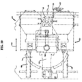
- Fig 12 is an enlarged representation of chuck assembly 70, as shown in Fig. 11B, further showing in greater detail additional internal features. Elements of structure that previously have been discussed are similarly designated.
- chuck assembly 70 is provided with a rotatable housing 200 and a non-rotating housing 201. The rotating and non-rotating housings are shown on opposite sides of bearings 190.
- Rotatable housing 200 is coupled to housing 180 by a fastener 205.
- housing 180 is also rotatable.
- Non-rotating housing 201 has a stationary fluid inlet port 207 that, in this specific illustrative embodiment of the invention, receives pressurized fluid (not shown) from a source (not shown).
- the pressurized fluid received at stationary fluid inlet port 207 is delivered via an internal channel 208 to an unclamping supply port 209 for effecting unclamping of chuck jaws 71.
- Pressurized fluid for clamping of the chuck jaws is received at a clamping fluid inlet port 210 that is connected by a channel 212 (shown in phantom) to chuck jaws 71".
- Further fluid channels (not shown) are provided to supply pressurized fluid for clamping and unclamping to the other chuck jaws.
- unclamping supply port 209 and clamping fluid inlet port 210 are but labyrinth grooves in non-rotating housing 201 at the interface of rotatable housing 200.
- End seals 215 and 216 limit leakage to the bearings of the fluid that bypasses internal drain port 220.
- two such drain ports are provided. Fluid that is bypassed via the bearings is expelled at drain line 194, and the remaining fluid is expelled at external port 193.
Landscapes
- Engineering & Computer Science (AREA)
- Mechanical Engineering (AREA)
- General Engineering & Computer Science (AREA)
- Physics & Mathematics (AREA)
- Optics & Photonics (AREA)
- Ocean & Marine Engineering (AREA)
- Pressure Welding/Diffusion-Bonding (AREA)
- Shafts, Cranks, Connecting Bars, And Related Bearings (AREA)
- Automatic Assembly (AREA)
- Golf Clubs (AREA)
- Residential Or Office Buildings (AREA)
- Motor Power Transmission Devices (AREA)
- Nitrogen And Oxygen Or Sulfur-Condensed Heterocyclic Ring Systems (AREA)
- Jib Cranes (AREA)
- Pivots And Pivotal Connections (AREA)
Applications Claiming Priority (7)
| Application Number | Priority Date | Filing Date | Title |
|---|---|---|---|
| US31374101P | 2001-08-20 | 2001-08-20 | |
| US31373901P | 2001-08-20 | 2001-08-20 | |
| US31373401P | 2001-08-20 | 2001-08-20 | |
| US313734P | 2001-08-20 | ||
| US313741P | 2001-08-20 | ||
| US313739P | 2001-08-20 | ||
| PCT/US2002/026562 WO2003066271A1 (en) | 2001-08-20 | 2002-08-20 | Synchronized tubular friction welding arrangement |
Publications (2)
| Publication Number | Publication Date |
|---|---|
| EP1429886A1 EP1429886A1 (en) | 2004-06-23 |
| EP1429886B1 true EP1429886B1 (en) | 2006-03-01 |
Family
ID=27739121
Family Applications (3)
| Application Number | Title | Priority Date | Filing Date |
|---|---|---|---|
| EP02768634A Withdrawn EP1421288A1 (en) | 2001-08-20 | 2002-08-20 | Shaft truing system |
| EP02766042A Expired - Lifetime EP1429886B1 (en) | 2001-08-20 | 2002-08-20 | Synchronised tubular friction welding arrangement and method |
| EP02757360A Withdrawn EP1421289A1 (en) | 2001-08-20 | 2002-08-20 | True vehicle running center shaft assembly system |
Family Applications Before (1)
| Application Number | Title | Priority Date | Filing Date |
|---|---|---|---|
| EP02768634A Withdrawn EP1421288A1 (en) | 2001-08-20 | 2002-08-20 | Shaft truing system |
Family Applications After (1)
| Application Number | Title | Priority Date | Filing Date |
|---|---|---|---|
| EP02757360A Withdrawn EP1421289A1 (en) | 2001-08-20 | 2002-08-20 | True vehicle running center shaft assembly system |
Country Status (9)
| Country | Link |
|---|---|
| US (1) | US7162903B2 (enExample) |
| EP (3) | EP1421288A1 (enExample) |
| JP (3) | JP2005516774A (enExample) |
| AT (1) | ATE318675T1 (enExample) |
| AU (3) | AU2002329793A1 (enExample) |
| CA (3) | CA2457046A1 (enExample) |
| DE (1) | DE60209512D1 (enExample) |
| MX (3) | MXPA04001592A (enExample) |
| WO (2) | WO2003066271A1 (enExample) |
Cited By (1)
| Publication number | Priority date | Publication date | Assignee | Title |
|---|---|---|---|---|
| CN112792475A (zh) * | 2021-03-25 | 2021-05-14 | 苏州康克莱自动化科技有限公司 | 横杆与接头焊接设备及同步焊接方法 |
Families Citing this family (13)
| Publication number | Priority date | Publication date | Assignee | Title |
|---|---|---|---|---|
| JP5042059B2 (ja) * | 2008-02-13 | 2012-10-03 | 富士フイルム株式会社 | 内視鏡用可撓管のエージング装置及びエージング方法 |
| CN102114503B (zh) * | 2010-12-08 | 2012-11-14 | 太原重工股份有限公司 | 卧式矫直机管棒料的旋转机构 |
| KR101365524B1 (ko) | 2011-12-19 | 2014-02-21 | (주)포스코 | 롤샤프트 교정 장치 |
| EP2996837B1 (en) * | 2013-05-13 | 2017-04-05 | Dana Automotive Systems Group, LLC | A method of joining workpieces |
| WO2015057201A1 (en) * | 2013-10-15 | 2015-04-23 | Ellwood National Investment Corp. | Open containment frame for roller compression treatment of rotating shaft products |
| US9228820B2 (en) * | 2014-02-11 | 2016-01-05 | Chin-Chang Huang | Straightness measuring instrument |
| CN104438960A (zh) * | 2014-11-13 | 2015-03-25 | 成都迅德科技有限公司 | 一种钢筋矫直机 |
| CN106670266A (zh) * | 2017-02-27 | 2017-05-17 | 福建恒劲科博测控技术有限公司 | 一种凸轮轴专用三轴自动矫直机及自动矫直方法 |
| CN111974833B (zh) * | 2020-09-03 | 2024-10-15 | 浙江索兰德环境科技有限公司 | 一种铝管调直器 |
| CN115283484A (zh) * | 2022-07-28 | 2022-11-04 | 盘星新型合金材料(常州)有限公司 | 非晶转轴用变形整形治具及变形整形方法、应用 |
| CN115709345B (zh) * | 2022-11-04 | 2024-09-03 | 盐城美联桥汽车部件有限公司 | 一种波纹管激光焊辅助方法 |
| CN117415190B (zh) * | 2023-12-18 | 2024-03-05 | 山西正大制管有限公司 | 一种加工镀锌管道用矫直机 |
| CN118080613B (zh) * | 2024-04-29 | 2024-07-02 | 潍坊潍尔达石油机械有限公司 | 多辊矫直装置及矫直工艺 |
Family Cites Families (24)
| Publication number | Priority date | Publication date | Assignee | Title |
|---|---|---|---|---|
| US3269002A (en) * | 1959-08-12 | 1966-08-30 | American Mach & Foundry | Friction welding |
| US3213659A (en) * | 1963-01-28 | 1965-10-26 | Ohio Crankshaft Co | Apparatus and method for straightening metal shafts |
| US3253444A (en) * | 1963-07-11 | 1966-05-31 | Gen Motors Corp | Method and apparatus for straightening tubular members |
| US3316743A (en) * | 1963-07-26 | 1967-05-02 | Herbert C Ovshinsky | Straightening machine |
| GB1074747A (en) * | 1963-11-08 | 1967-07-05 | American Brake Shoe Co | Apparatus for straightening shafts |
| FR1416365A (fr) * | 1964-04-10 | 1965-11-05 | American Mach & Foundry | Soudage par frottement |
| FR1455696A (fr) * | 1964-12-01 | 1966-04-01 | Steelweld Ltd | Appareil pour la soudure par frottement |
| US3583191A (en) * | 1969-02-13 | 1971-06-08 | Cargill Detroit Corp | Compressive straightener |
| GB1293141A (en) * | 1969-07-16 | 1972-10-18 | Welding Inst | Improvements relating to friction welding |
| US3684856A (en) * | 1971-06-28 | 1972-08-15 | Lifshits V S | Resistance butt welding machine |
| US3800995A (en) * | 1972-08-25 | 1974-04-02 | Production Technology Inc | Twin-spindle inertia welding machine |
| US3823588A (en) * | 1972-10-19 | 1974-07-16 | Newport News Shipbuilding | Method and system for straightening large diameter shafts by selective cold rolling |
| FR2218156B2 (enExample) * | 1973-02-21 | 1976-09-10 | Naphtachimie Sa | |
| CA1035267A (en) * | 1974-11-21 | 1978-07-25 | Royston P. Jenkin | Pipe straightening and spinning apparatus |
| US4087036A (en) * | 1976-10-14 | 1978-05-02 | Pemtec, Inc. | Friction welding method and apparatus |
| DE2905386A1 (de) * | 1979-02-13 | 1980-10-02 | Hornbacher Karl Heinz Ing Grad | Einrichtung zum automatischen richten von wellen |
| US4700439A (en) * | 1984-07-17 | 1987-10-20 | Hines Industries, Inc. | Driveshaft fabricating apparatus |
| US4624123A (en) * | 1985-05-07 | 1986-11-25 | Bertolette Machines, Inc. | Straightening machine for motor armature assemblies and the like |
| US4788844A (en) * | 1987-05-01 | 1988-12-06 | Inventive Enterprises Inc. | Apparatus for straightening slender shafts |
| US5253499A (en) | 1992-06-11 | 1993-10-19 | Dana Corporation | Method for straightening coupling shafts |
| JPH1177338A (ja) * | 1997-09-03 | 1999-03-23 | Mitsubishi Heavy Ind Ltd | 摩擦接合方法 |
| JP3209170B2 (ja) * | 1997-12-02 | 2001-09-17 | 日本軽金属株式会社 | アルミニウム合金製中空部材の摩擦圧接方法及び継手 |
| EP1178867B1 (en) * | 1998-11-02 | 2004-09-29 | Spinduction Weld, Inc. | Improved method of solid state welding and welded parts |
| JP2000288746A (ja) * | 1999-04-07 | 2000-10-17 | Kawasaki Steel Corp | 棒材のクランプ装置 |
-
2002
- 2002-08-20 CA CA002457046A patent/CA2457046A1/en not_active Abandoned
- 2002-08-20 AU AU2002329793A patent/AU2002329793A1/en not_active Abandoned
- 2002-08-20 EP EP02768634A patent/EP1421288A1/en not_active Withdrawn
- 2002-08-20 MX MXPA04001592A patent/MXPA04001592A/es unknown
- 2002-08-20 US US10/487,289 patent/US7162903B2/en not_active Expired - Fee Related
- 2002-08-20 JP JP2003565682A patent/JP2005516774A/ja active Pending
- 2002-08-20 MX MXPA04001594A patent/MXPA04001594A/es unknown
- 2002-08-20 CA CA002457190A patent/CA2457190A1/en not_active Abandoned
- 2002-08-20 AU AU2002331656A patent/AU2002331656A1/en not_active Abandoned
- 2002-08-20 CA CA002457874A patent/CA2457874A1/en not_active Abandoned
- 2002-08-20 WO PCT/US2002/026562 patent/WO2003066271A1/en not_active Ceased
- 2002-08-20 JP JP2003578762A patent/JP2005519767A/ja active Pending
- 2002-08-20 EP EP02766042A patent/EP1429886B1/en not_active Expired - Lifetime
- 2002-08-20 MX MXPA04001593A patent/MXPA04001593A/es unknown
- 2002-08-20 WO PCT/US2002/026567 patent/WO2003081060A1/en not_active Ceased
- 2002-08-20 JP JP2003571619A patent/JP2005518512A/ja active Pending
- 2002-08-20 EP EP02757360A patent/EP1421289A1/en not_active Withdrawn
- 2002-08-20 DE DE60209512T patent/DE60209512D1/de not_active Expired - Lifetime
- 2002-08-20 AU AU2002323380A patent/AU2002323380A1/en not_active Abandoned
- 2002-08-20 AT AT02766042T patent/ATE318675T1/de not_active IP Right Cessation
Cited By (1)
| Publication number | Priority date | Publication date | Assignee | Title |
|---|---|---|---|---|
| CN112792475A (zh) * | 2021-03-25 | 2021-05-14 | 苏州康克莱自动化科技有限公司 | 横杆与接头焊接设备及同步焊接方法 |
Also Published As
| Publication number | Publication date |
|---|---|
| JP2005516774A (ja) | 2005-06-09 |
| ATE318675T1 (de) | 2006-03-15 |
| CA2457874A1 (en) | 2003-08-14 |
| JP2005518512A (ja) | 2005-06-23 |
| EP1421289A1 (en) | 2004-05-26 |
| DE60209512D1 (de) | 2006-04-27 |
| MXPA04001592A (es) | 2005-09-08 |
| MXPA04001594A (es) | 2005-07-25 |
| AU2002329793A1 (en) | 2003-09-02 |
| CA2457190A1 (en) | 2003-09-04 |
| US7162903B2 (en) | 2007-01-16 |
| EP1429886A1 (en) | 2004-06-23 |
| AU2002323380A1 (en) | 2003-09-09 |
| MXPA04001593A (es) | 2005-09-08 |
| CA2457046A1 (en) | 2003-10-02 |
| AU2002331656A1 (en) | 2003-10-08 |
| US20040231381A1 (en) | 2004-11-25 |
| EP1421288A1 (en) | 2004-05-26 |
| WO2003066271A1 (en) | 2003-08-14 |
| WO2003081060A1 (en) | 2003-10-02 |
| JP2005519767A (ja) | 2005-07-07 |
Similar Documents
| Publication | Publication Date | Title |
|---|---|---|
| EP1429886B1 (en) | Synchronised tubular friction welding arrangement and method | |
| US5845384A (en) | Joining system and method of detachably and securely joining two members | |
| US7275677B2 (en) | Synchronized tubular friction welding arrangement | |
| US20070228104A1 (en) | Friction stir welding spindle assembly | |
| GB2070489A (en) | Intermediate workpiece supporting in crankshaft or camshaft milling | |
| JPS61121805A (ja) | 心棒組立体 | |
| KR100552647B1 (ko) | 중공제품, 상기 중공제품을 제조하는 방법과 장치, 및상기 중공제품을 사용하는 유체이송시스템 | |
| JPS62502521A (ja) | 摩擦溶接装置 | |
| JP2557017B2 (ja) | 長尺管用摩擦圧接機 | |
| JP2005516774A5 (enExample) | ||
| JP3204205B2 (ja) | 等速自在継手の加工治具 | |
| US7275295B2 (en) | True vehicle running center shaft assembly system | |
| JP3743483B2 (ja) | 組付方法および組付装置 | |
| US3576289A (en) | Combined spindle and internal chuck for friction welder | |
| JPH05196790A (ja) | 燃料棒における端栓の溶接装置 | |
| US20090001136A1 (en) | Apparatus and Method for Rotational Friction Welding | |
| JP2001062615A (ja) | 工作物把持装置及び同装置を用いた加工方法 | |
| CN112757064A (zh) | 磨床传动机构 | |
| JPH09239607A (ja) | フェースクランプチャック | |
| JPS622921B2 (enExample) | ||
| JPH0413082B2 (enExample) | ||
| JP3012777B2 (ja) | 外輪部材の芯出し保持装置 | |
| JPH0521308Y2 (enExample) | ||
| JPS62251001A (ja) | リード面加工装置 | |
| JPH10328907A (ja) | 工作機械 |
Legal Events
| Date | Code | Title | Description |
|---|---|---|---|
| PUAI | Public reference made under article 153(3) epc to a published international application that has entered the european phase |
Free format text: ORIGINAL CODE: 0009012 |
|
| 17P | Request for examination filed |
Effective date: 20040319 |
|
| AK | Designated contracting states |
Kind code of ref document: A1 Designated state(s): AT BE BG CH CY CZ DE DK EE ES FI FR GB GR IE IT LI LU MC NL PT SE SK TR |
|
| AX | Request for extension of the european patent |
Extension state: AL LT LV MK RO SI |
|
| RIN1 | Information on inventor provided before grant (corrected) |
Inventor name: OLSCHEFSKI, ROBERT, D. Inventor name: JURANITCH, JAMES, C. |
|
| 17Q | First examination report despatched |
Effective date: 20040929 |
|
| GRAP | Despatch of communication of intention to grant a patent |
Free format text: ORIGINAL CODE: EPIDOSNIGR1 |
|
| RTI1 | Title (correction) |
Free format text: SYNCHRONISED TUBULAR FRICTION WELDING ARRANGEMENT AND METHOD |
|
| RTI1 | Title (correction) |
Free format text: SYNCHRONISED TUBULAR FRICTION WELDING ARRANGEMENT AND METHOD |
|
| GRAS | Grant fee paid |
Free format text: ORIGINAL CODE: EPIDOSNIGR3 |
|
| GRAA | (expected) grant |
Free format text: ORIGINAL CODE: 0009210 |
|
| AK | Designated contracting states |
Kind code of ref document: B1 Designated state(s): AT BE BG CH CY CZ DE DK EE ES FI FR GB GR IE IT LI LU MC NL PT SE SK TR |
|
| PG25 | Lapsed in a contracting state [announced via postgrant information from national office to epo] |
Ref country code: FI Free format text: LAPSE BECAUSE OF FAILURE TO SUBMIT A TRANSLATION OF THE DESCRIPTION OR TO PAY THE FEE WITHIN THE PRESCRIBED TIME-LIMIT Effective date: 20060301 Ref country code: IT Free format text: LAPSE BECAUSE OF FAILURE TO SUBMIT A TRANSLATION OF THE DESCRIPTION OR TO PAY THE FEE WITHIN THE PRESCRIBED TIME-LIMIT;WARNING: LAPSES OF ITALIAN PATENTS WITH EFFECTIVE DATE BEFORE 2007 MAY HAVE OCCURRED AT ANY TIME BEFORE 2007. THE CORRECT EFFECTIVE DATE MAY BE DIFFERENT FROM THE ONE RECORDED. Effective date: 20060301 Ref country code: SK Free format text: LAPSE BECAUSE OF FAILURE TO SUBMIT A TRANSLATION OF THE DESCRIPTION OR TO PAY THE FEE WITHIN THE PRESCRIBED TIME-LIMIT Effective date: 20060301 Ref country code: BE Free format text: LAPSE BECAUSE OF FAILURE TO SUBMIT A TRANSLATION OF THE DESCRIPTION OR TO PAY THE FEE WITHIN THE PRESCRIBED TIME-LIMIT Effective date: 20060301 Ref country code: CH Free format text: LAPSE BECAUSE OF FAILURE TO SUBMIT A TRANSLATION OF THE DESCRIPTION OR TO PAY THE FEE WITHIN THE PRESCRIBED TIME-LIMIT Effective date: 20060301 Ref country code: AT Free format text: LAPSE BECAUSE OF FAILURE TO SUBMIT A TRANSLATION OF THE DESCRIPTION OR TO PAY THE FEE WITHIN THE PRESCRIBED TIME-LIMIT Effective date: 20060301 Ref country code: NL Free format text: LAPSE BECAUSE OF FAILURE TO SUBMIT A TRANSLATION OF THE DESCRIPTION OR TO PAY THE FEE WITHIN THE PRESCRIBED TIME-LIMIT Effective date: 20060301 Ref country code: LI Free format text: LAPSE BECAUSE OF FAILURE TO SUBMIT A TRANSLATION OF THE DESCRIPTION OR TO PAY THE FEE WITHIN THE PRESCRIBED TIME-LIMIT Effective date: 20060301 |
|
| REG | Reference to a national code |
Ref country code: GB Ref legal event code: FG4D |
|
| REG | Reference to a national code |
Ref country code: CH Ref legal event code: EP |
|
| REG | Reference to a national code |
Ref country code: IE Ref legal event code: FG4D |
|
| REF | Corresponds to: |
Ref document number: 60209512 Country of ref document: DE Date of ref document: 20060427 Kind code of ref document: P |
|
| PG25 | Lapsed in a contracting state [announced via postgrant information from national office to epo] |
Ref country code: DK Free format text: LAPSE BECAUSE OF FAILURE TO SUBMIT A TRANSLATION OF THE DESCRIPTION OR TO PAY THE FEE WITHIN THE PRESCRIBED TIME-LIMIT Effective date: 20060601 Ref country code: SE Free format text: LAPSE BECAUSE OF FAILURE TO SUBMIT A TRANSLATION OF THE DESCRIPTION OR TO PAY THE FEE WITHIN THE PRESCRIBED TIME-LIMIT Effective date: 20060601 Ref country code: BG Free format text: LAPSE BECAUSE OF FAILURE TO SUBMIT A TRANSLATION OF THE DESCRIPTION OR TO PAY THE FEE WITHIN THE PRESCRIBED TIME-LIMIT Effective date: 20060601 |
|
| PG25 | Lapsed in a contracting state [announced via postgrant information from national office to epo] |
Ref country code: DE Free format text: LAPSE BECAUSE OF FAILURE TO SUBMIT A TRANSLATION OF THE DESCRIPTION OR TO PAY THE FEE WITHIN THE PRESCRIBED TIME-LIMIT Effective date: 20060602 |
|
| PG25 | Lapsed in a contracting state [announced via postgrant information from national office to epo] |
Ref country code: ES Free format text: LAPSE BECAUSE OF FAILURE TO SUBMIT A TRANSLATION OF THE DESCRIPTION OR TO PAY THE FEE WITHIN THE PRESCRIBED TIME-LIMIT Effective date: 20060612 |
|
| PG25 | Lapsed in a contracting state [announced via postgrant information from national office to epo] |
Ref country code: PT Free format text: LAPSE BECAUSE OF FAILURE TO SUBMIT A TRANSLATION OF THE DESCRIPTION OR TO PAY THE FEE WITHIN THE PRESCRIBED TIME-LIMIT Effective date: 20060801 |
|
| PG25 | Lapsed in a contracting state [announced via postgrant information from national office to epo] |
Ref country code: IE Free format text: LAPSE BECAUSE OF NON-PAYMENT OF DUE FEES Effective date: 20060821 |
|
| PG25 | Lapsed in a contracting state [announced via postgrant information from national office to epo] |
Ref country code: MC Free format text: LAPSE BECAUSE OF NON-PAYMENT OF DUE FEES Effective date: 20060831 |
|
| NLV1 | Nl: lapsed or annulled due to failure to fulfill the requirements of art. 29p and 29m of the patents act | ||
| REG | Reference to a national code |
Ref country code: CH Ref legal event code: PL |
|
| PLBE | No opposition filed within time limit |
Free format text: ORIGINAL CODE: 0009261 |
|
| STAA | Information on the status of an ep patent application or granted ep patent |
Free format text: STATUS: NO OPPOSITION FILED WITHIN TIME LIMIT |
|
| 26N | No opposition filed |
Effective date: 20061204 |
|
| GBPC | Gb: european patent ceased through non-payment of renewal fee |
Effective date: 20060820 |
|
| EN | Fr: translation not filed | ||
| PG25 | Lapsed in a contracting state [announced via postgrant information from national office to epo] |
Ref country code: GB Free format text: LAPSE BECAUSE OF NON-PAYMENT OF DUE FEES Effective date: 20060820 |
|
| PG25 | Lapsed in a contracting state [announced via postgrant information from national office to epo] |
Ref country code: GR Free format text: LAPSE BECAUSE OF FAILURE TO SUBMIT A TRANSLATION OF THE DESCRIPTION OR TO PAY THE FEE WITHIN THE PRESCRIBED TIME-LIMIT Effective date: 20060602 Ref country code: FR Free format text: LAPSE BECAUSE OF FAILURE TO SUBMIT A TRANSLATION OF THE DESCRIPTION OR TO PAY THE FEE WITHIN THE PRESCRIBED TIME-LIMIT Effective date: 20070309 Ref country code: CZ Free format text: LAPSE BECAUSE OF FAILURE TO SUBMIT A TRANSLATION OF THE DESCRIPTION OR TO PAY THE FEE WITHIN THE PRESCRIBED TIME-LIMIT Effective date: 20060301 |
|
| PG25 | Lapsed in a contracting state [announced via postgrant information from national office to epo] |
Ref country code: EE Free format text: LAPSE BECAUSE OF FAILURE TO SUBMIT A TRANSLATION OF THE DESCRIPTION OR TO PAY THE FEE WITHIN THE PRESCRIBED TIME-LIMIT Effective date: 20060301 |
|
| PG25 | Lapsed in a contracting state [announced via postgrant information from national office to epo] |
Ref country code: LU Free format text: LAPSE BECAUSE OF NON-PAYMENT OF DUE FEES Effective date: 20060820 Ref country code: TR Free format text: LAPSE BECAUSE OF FAILURE TO SUBMIT A TRANSLATION OF THE DESCRIPTION OR TO PAY THE FEE WITHIN THE PRESCRIBED TIME-LIMIT Effective date: 20060301 |
|
| PG25 | Lapsed in a contracting state [announced via postgrant information from national office to epo] |
Ref country code: FR Free format text: LAPSE BECAUSE OF FAILURE TO SUBMIT A TRANSLATION OF THE DESCRIPTION OR TO PAY THE FEE WITHIN THE PRESCRIBED TIME-LIMIT Effective date: 20060301 Ref country code: CY Free format text: LAPSE BECAUSE OF FAILURE TO SUBMIT A TRANSLATION OF THE DESCRIPTION OR TO PAY THE FEE WITHIN THE PRESCRIBED TIME-LIMIT Effective date: 20060301 |