EP1428279B1 - Flow field - Google Patents
Flow field Download PDFInfo
- Publication number
- EP1428279B1 EP1428279B1 EP02761318A EP02761318A EP1428279B1 EP 1428279 B1 EP1428279 B1 EP 1428279B1 EP 02761318 A EP02761318 A EP 02761318A EP 02761318 A EP02761318 A EP 02761318A EP 1428279 B1 EP1428279 B1 EP 1428279B1
- Authority
- EP
- European Patent Office
- Prior art keywords
- flow field
- channel
- flow
- fluid
- serpentine
- Prior art date
- Legal status (The legal status is an assumption and is not a legal conclusion. Google has not performed a legal analysis and makes no representation as to the accuracy of the status listed.)
- Expired - Lifetime
Links
Images


Classifications
-
- H—ELECTRICITY
- H01—ELECTRIC ELEMENTS
- H01M—PROCESSES OR MEANS, e.g. BATTERIES, FOR THE DIRECT CONVERSION OF CHEMICAL ENERGY INTO ELECTRICAL ENERGY
- H01M8/00—Fuel cells; Manufacture thereof
- H01M8/02—Details
-
- H—ELECTRICITY
- H01—ELECTRIC ELEMENTS
- H01M—PROCESSES OR MEANS, e.g. BATTERIES, FOR THE DIRECT CONVERSION OF CHEMICAL ENERGY INTO ELECTRICAL ENERGY
- H01M8/00—Fuel cells; Manufacture thereof
- H01M8/02—Details
- H01M8/0202—Collectors; Separators, e.g. bipolar separators; Interconnectors
- H01M8/0258—Collectors; Separators, e.g. bipolar separators; Interconnectors characterised by the configuration of channels, e.g. by the flow field of the reactant or coolant
- H01M8/026—Collectors; Separators, e.g. bipolar separators; Interconnectors characterised by the configuration of channels, e.g. by the flow field of the reactant or coolant characterised by grooves, e.g. their pitch or depth
-
- H—ELECTRICITY
- H01—ELECTRIC ELEMENTS
- H01M—PROCESSES OR MEANS, e.g. BATTERIES, FOR THE DIRECT CONVERSION OF CHEMICAL ENERGY INTO ELECTRICAL ENERGY
- H01M8/00—Fuel cells; Manufacture thereof
- H01M8/02—Details
- H01M8/0202—Collectors; Separators, e.g. bipolar separators; Interconnectors
- H01M8/0258—Collectors; Separators, e.g. bipolar separators; Interconnectors characterised by the configuration of channels, e.g. by the flow field of the reactant or coolant
- H01M8/0263—Collectors; Separators, e.g. bipolar separators; Interconnectors characterised by the configuration of channels, e.g. by the flow field of the reactant or coolant having meandering or serpentine paths
-
- H—ELECTRICITY
- H01—ELECTRIC ELEMENTS
- H01M—PROCESSES OR MEANS, e.g. BATTERIES, FOR THE DIRECT CONVERSION OF CHEMICAL ENERGY INTO ELECTRICAL ENERGY
- H01M8/00—Fuel cells; Manufacture thereof
- H01M8/02—Details
- H01M8/0202—Collectors; Separators, e.g. bipolar separators; Interconnectors
- H01M8/0258—Collectors; Separators, e.g. bipolar separators; Interconnectors characterised by the configuration of channels, e.g. by the flow field of the reactant or coolant
- H01M8/0265—Collectors; Separators, e.g. bipolar separators; Interconnectors characterised by the configuration of channels, e.g. by the flow field of the reactant or coolant the reactant or coolant channels having varying cross sections
-
- Y—GENERAL TAGGING OF NEW TECHNOLOGICAL DEVELOPMENTS; GENERAL TAGGING OF CROSS-SECTIONAL TECHNOLOGIES SPANNING OVER SEVERAL SECTIONS OF THE IPC; TECHNICAL SUBJECTS COVERED BY FORMER USPC CROSS-REFERENCE ART COLLECTIONS [XRACs] AND DIGESTS
- Y02—TECHNOLOGIES OR APPLICATIONS FOR MITIGATION OR ADAPTATION AGAINST CLIMATE CHANGE
- Y02E—REDUCTION OF GREENHOUSE GAS [GHG] EMISSIONS, RELATED TO ENERGY GENERATION, TRANSMISSION OR DISTRIBUTION
- Y02E60/00—Enabling technologies; Technologies with a potential or indirect contribution to GHG emissions mitigation
- Y02E60/30—Hydrogen technology
- Y02E60/50—Fuel cells
-
- Y—GENERAL TAGGING OF NEW TECHNOLOGICAL DEVELOPMENTS; GENERAL TAGGING OF CROSS-SECTIONAL TECHNOLOGIES SPANNING OVER SEVERAL SECTIONS OF THE IPC; TECHNICAL SUBJECTS COVERED BY FORMER USPC CROSS-REFERENCE ART COLLECTIONS [XRACs] AND DIGESTS
- Y10—TECHNICAL SUBJECTS COVERED BY FORMER USPC
- Y10T—TECHNICAL SUBJECTS COVERED BY FORMER US CLASSIFICATION
- Y10T428/00—Stock material or miscellaneous articles
- Y10T428/24—Structurally defined web or sheet [e.g., overall dimension, etc.]
- Y10T428/24355—Continuous and nonuniform or irregular surface on layer or component [e.g., roofing, etc.]
Definitions
- This invention relates to flow fields for uniform distribution of fluids or their active components or properties to and from a target area.
- the flow field may be embodied in a flow field device such as a flow field plate or bipolar plate used for distribution of reactants to, and removal of products from, opposite sides of a catalyzed membrane in an electrochemical cell such as a fuel cell.
- references depict flow fields having multiple interleaved serpentine channels wherein sequential segments of each channel are parallel, including: U.S. Pats. Nos. 5,683,828 ; 5,750,281 ; 5,773,160 ; 5,804,326 ; 5,840,438 ; 5,858,567 ; 5,998,055 ; 6,071,635 and 6,093,502 .
- U.S. Pat. No. 5,922,485 depicts flow fields having serpentine channels composed of concentric circular segments, as well as straight-line serpentine channels.
- U.S. Pat. No. 6,048,634 depicts flow field patterns wherein pairs of adjacent channels carry flow in opposite directions, including spiral patterns and serpentine patterns wherein sequential segments of the channels are parallel.
- U.S. Pat. No. 4,292,379 describes flow fields on either side of a bipolar plate wherein the depth and/or separation of parallel channels are varied so as to create an uneven distribution that matches the uneven distribution created by the opposing face of the plate.
- U.S. Pat. No. 4,324,844 concerns an electrochemical cell that includes cooling fluid flow passages having varying surface area and spacing.
- WO 02/056402 relates to an electrochemical fuel cell stack comprising a membrane-electrode-unit and a distributor plate comprising a channel area with gas channels for distributing anode or cathode gas to the membrane-electrode-unit.
- the gas channel sections of a gas channel are situated in parallel to one another. According to an other embodiment, the gas channel sections are not running in parallel with one another but instead form one constant angle to one another.
- EP1075033 relates to a planar fuel cell stack with spiral-shaped channels.
- JP 2000 003715 relates to solid electrolyte fuel cell with flow passages which radially extend from a central part to the peripheral part with an equal angle space.
- US 5,922,485 relates to a solid polymer electrolyte fuel cell.
- the solid polymer electrolyte fuel cell features a unit cell structure including separators, each including an oxidant gas inlet, fuel gas inlets, coolant inlets, an oxidant gas outlet, fuel gas outlets and coolant outlets.
- the inlets are arranged in a peripheral region of the separators and the outlets in a central region of the separators.
- the oxidant gas, fuel gas and coolant are made to flow from the peripheral region to the central region such that the temperatures of the oxidant and fuel gases are higher near the reactant gas outlets.
- a continuous coolant flow path is provided by forming protrusions in the reactant gas conduits.
- the present invention provides a fluid distribution assembly comprising a flow field device embodying a flow field and a fluid transport layer disposed between the flow field device and a target area, where, for at least one finite non-zero flow rate and at least one use rate of an active component or property of the fluid in the fluid transport layer, lateral flux of the active component or property varies by no more than 35% through at least 90% of all overland portions of said fluid transport layer.
- the flow field device of the present invention is a flow field device embodying a flow field comprising at least one serpentine channel comprising major segments wherein at least three sequential major segments of said serpentine channel are non-parallel wherein said serpentine channel has an inlet, wherein sequential major segments of said serpentine channel form acute angles, and wherein said acute angles decrease monotonically with distance from the inlet, as measured along said channel.
- the present invention provides flow fields for uniform distribution of fluids or their active components or properties to and from a target area.
- the flow field may be embodied in a flow field plate or bipolar plate used for distribution of reactants to, and removal of products from, opposite sides of a catalyzed membrane in an electrochemical cell such as a fuel cell.
- the flow fields according to the present invention are typically embodied in a flow field device, which is typically separated from the target area by a fluid transport layer.
- the flow fields according to the present invention provide more uniform access of the fluid or its active component or property to the target area, by providing highly uniform lateral flux through the fluid transport layer separating the flow field from the target area for the transported fluid.
- the flow field according to the present invention may be embodied in a flow field device such as a bipolar plate (BPP) for an electrochemical cell such as a fuel cell.
- Electrochemical cells include fuel cells, sensors, electrolyzers, and electrochemical reactors. Fuel cells utilize a fuel such as hydrogen and an oxidizing agent such as oxygen to produce an electrical current. The two chemical reactants, i.e., the fuel and the oxidizing agent, separately react at two isolated electrodes containing catalyst. An ion exchange element is located between the electrodes to prevent direct chemical reaction of the two reactants and to conduct ions. In the case of a typical hydrogen fuel cell, the ion exchange element is an ion conducting membrane (ICM).
- ICM ion conducting membrane
- the ICM conducts protons (H + ) from the hydrogen electrode to the oxygen electrode. Electrons follow a separate external electrical path, thereby generating an electric current.
- the combination of an ICM and electrodes is commonly referred to as a "membrane electrode assembly," or MEA.
- the catalyst electrode material may be coated directly on the ICM to form a catalyst-coated membrane, or may be coated on the fluid transport layer discussed below.
- bipolar plates In conventional fuel cells, MEA's are arranged in a stack separated by rigid, electrically-conductive plates which may be known as bipolar plates (BPP).
- the bipolar plate has one or more fluid-conducting channels engraved, milled, molded or stamped in the surface(s) facing the MEA(s).
- the fluid-conducting channels on one side of the plate direct fuel to the anode of one MEA while the channels on the other side direct oxidant to the cathode of the next MEA in the stack.
- the bipolar plates conduct the electrical current generated in each MEA throughout the stack.
- bipolar plate should be understood to include the end plates of a stack, which perform the functions of the bipolar plate on one side only and serve the first and last MEA's of the stack.
- a stack having a single MEA has only two end plates, which are both encompassed by the term "bipolar plate” as used herein.
- DCC diffuser/current collector
- gas diffusion layer gas diffusion layer
- electrode backing layer an additional fluid transport layer is typically situated between the bipolar plate and the active catalytic sites of the MEA.
- DCC diffuser/current collector
- gas diffusion layer gas diffusion layer
- electrode backing layer an additional fluid transport layer is typically situated between the bipolar plate and the active catalytic sites of the MEA.
- DCC diffuser/current collector
- gas diffusion layer gas diffusion layer
- electrode backing layer the term DCC is a part of the MEA.
- typical DCC's are porous throughout and do not function as structural members.
- the DCC typically comprises carbon fiber paper, non-woven roll goods, or cloth such as ELAT TM electrode backing material (E-tek, Inc., Natick, MA), typically at a thickness of about 0.4 mm.
- ELAT TM electrode backing material E-tek, Inc., Natick, MA
- Another typical material is Toray Carbon Paper (Toray Industries, Inc., Tokyo, Japan), typically at a thickness of about 0.2 mm, which may additionally be coated with a carbon particle dispersion.
- Uniform distribution of fuel and oxidants over the catalyst electrodes in a fuel cell should result in more uniform utilization of the catalyst, resulting in better performance, stability and durability. Furthermore, this is expected to result in more uniform distribution of current density (Amps/cm 2 ), and waste heat generation. This should reduce degradation mechanisms that are thermally related, and lead to better durability and longer lifetimes. It is desirable then to find methods to distribute reactant gases most uniformly over the surface of the target area.
- the partial pressures of fuel and oxidants at the surface of the catalyst at any given point in an electrode of a fuel cell are directly related to the speed of the lateral flux of the gas in the DCC above.
- Gasses are transported to the catalyst surface by a combination of diffusion and convection. Closest to the catalyst surface it is to be expected that gasses arrive by diffusion, subject to Fick's Law. The rate of transport in this diffusion-dominated zone is dependent on the gradient in concentration. Farther away from the catalyst surface, gas is transported by a combination of diffusion and convection. Since the gradient in the diffusion zone depends on the rate at which gasses are replenished by convection in the zone above, greater and more uniform lateral flux through the DCC should result in greater and more uniform flux of reactant gasses to the catalyst surface.
- the importance of convection as well as diffusion can be illustrated by considering the Peclet number for mass transport to the center of a land area.
- the Peclet number is one way of comparing the relative importance of convective transport to diffusive transport; it is defined as velocity times distance divided by the diffusivity. For a value of 1, convection and diffusion contribute equally.
- the flow fields according to the present invention advantageously include significant land areas.
- 40% or more of the active area of a flow field according to the present invention is land area; more typically 50% or more, more typically 60% or more, and more typically 70% or more.
- the flow field according to the present invention may comprise any number of channels.
- the flow field according to the present invention is typically composed of a single channel, but may alternately be composed of a channel composed of multiple courses effectively parallel to each other, such as depicted in Fig. 18 .
- the active area of the flow field may be any suitable size and shape, including rectangular, square, polygonal, circular, elliptical and irregular shapes.
- the active area corresponds to the target area, which may be any suitable size and shape, including rectangular, square, polygonal, circular, elliptical and irregular shapes.
- the active area may be subdivided into separate zones serving separate portions of the target area and treating each portion as a single target area, served by a single channel or a channel composed of multiple courses.
- the flow field channels may have any suitable cross-section, including rectangular and sloped-side cross-sections.
- the channels may comprise micro-flow channels or microstructured features as disclosed in U.S. Patent Applications S.N. 09/557,712 and 09/430,568 .
- the channels terminate at one end in an inlet, which is typically a single opening but may also be multiple openings, and may open into or comprise a manifold.
- the channels terminate at another end in an outlet, which is typically a single opening but may also be multiple openings, and may open into or comprise a manifold. Where the entire flow of gas into the flow field is to be consumed or removed through the fluid transport layer, no outlet is necessary.
- the fluid distributed by use of the flow field according to the present invention may be any fluid, including gasses, liquids, supercritical fluids, or combinations thereof.
- the fluid comprises an active component or has an active property, defined above.
- the active component may be the oxygen content of air supplied to the cathode side of the cell or the hydrogen content of a reformate fuel gas supplied to the anode side of the cell. If a pure hydrogen source is used, the active component is the entire fluid. In the case of hydrogen or oxygen, the active component is used up as it is partially or completely consumed in an electrochemical reaction.
- the use rate is the rate at which the active component is withdrawn from the fluid in the transport layer for consumption in the target area.
- the flow fields according to the present invention may be used for uniform distribution of cooling fluids, in a fuel cell or some other device.
- the active property is the thermal energy content of the coolant.
- the air and fuel flows may themselves function as cooling fluids.
- the use rate is the rate at which thermal energy is withdrawn from the active area into the fluid in the transport layer.
- the flow fields according to the present invention may be used for uniform distribution of solvents, in which case the active property is the solvating capacity of the fluid and the use rate is the rate at which solutes are dissolved from the active area into the fluid in the transport layer.
- the flow fields according to the present invention may be used for uniform distribution of air in a planar air bearing, in which case the active component is the entire gas and the use rate is the rate at which air escapes the bearing.
- the flow field according to the present invention is embodied in a flow field device.
- the flow field device may be made of any suitable material, but should be stable to the fluids transported and the conditions of use.
- Flow field plates or bipolar plates according to the present invention for use in fuel cells are typically made of an electrically conductive material such as a metal, including titanium and stainless steel or conductive carbon materials such as graphite or carbon composites. Alternately, materials may be used which are plated, vacuum coated or otherwise coated with conductive anti-corrosion layers by wet methods, vacuum methods, or any suitable method.
- the channel or channels of the flow field are cut, molded, stamped or otherwise formed into the flow field device by any suitable method.
- the bipolar plates of the present invention may be made by any suitable method, including the methods described in U.S. Patent No. 5,728,446, to Johnston, et. al ., and pending U.S. Patent Applications S.N. 09/099,269 , 09/557,712 and 09/430,568 .
- a flow field is cut, molded, stamped or otherwise formed into the material comprising the fluid transport layer.
- the adjacent "bipolar plate" may then be substantially flat, or may bear additional flow field channels.
- the fluid transport layer may be the DCC of a fuel cell, discussed above.
- the fluid transport layer may be made of any suitable porous or permeable material.
- the material is typically an electrically conductive carbon-based material.
- the fluid transport layer may be any suitable thickness.
- the fluid transport layer is typically less than 1 mm, more typically less than 500 microns (500 ⁇ m), and can be less than 300 microns (300 ⁇ m).
- the fluid transport layer is typically at least 50 (50 ⁇ m) microns in thickness.
- the fluid transport layer may have any suitable in-plane permeability for gasses, but is typically not greater than 1 x 10 -5 m 2 , typically between 1 x 10 -8 m 2 and 1 x 10 -13 m 2 and more typically between 1 x 10 -10 m 2 and 1 x 10 -12 m 2 .
- the fluid distribution assembly provides more uniform access of the fluid to the target area, by providing highly uniform lateral flux through the fluid transport layer separating the flow field from the target area.
- fluid flux may be determined by analysis of a flow field design using computational fluid dynamic (CFD) calculations.
- CFD is well established as an investigative tool for analyzing complex systems of fluid flow, and therefore any reliable CFD code may be used.
- the CFD code "Fluent” (ver. 5.5, Fluent, Inc., Riverside, New Hampshire) is used.
- This is a general purpose, finite volume code which uses a form of the SIMPLE method for computing the cell pressures and fluid velocities, using the assumptions of steady-state laminar flow with constant viscosity and temperature.
- Porous media such as the fluid transport layer
- Darcy's Law for which the pressure drop is linearly dependent on the viscosity and flow velocity and inversely dependent on permeability.
- the fluid distribution assembly typically provides uniformity to the extent that lateral flux of the active component varies by no more than 35% through at least 90% of all overland portions of the fluid transport layer. More typically, lateral flux of the active component varies by no more than 30% through at least 90% of all overland portions of the fluid transport layer, more typically by no more than 25%, and more typically by no more than 20%. It is assumed that there is a non-zero flow rate of a fluid into the inlet of the flow field, since, of course, any flow field will be uniformly still at zero flow. It is assumed that the desired uniformity can be achieved for at least one rate of use of the active component of the fluid, e.g. one rate of oxygen consumption, as described more fully below and in the Examples herein.
- Any suitable flow field design which provides uniform flux through the overland portions of the fluid transport layer can be used.
- designs having non-parallel sequential channel segments are used.
- progressive designs are used, where the distance between analogous parts of sequential major segments is progressively closer toward one end of a flow field channel, or where land areas separating the major segments decrease in size progressively with distance from the inlet.
- Designs having non-parallel sequential channel segments may include a "zig-zag" serpentine design, comprising at least one serpentine channel having non-parallel sequential major segments, such as depicted in Fig. 3 and schematically in Fig. 2 .
- the major segments may be curved, but are typically straight line segments. Turning segments may be made up of curved segments or one or more straight segments. Alternately, the major segments may meet at a point.
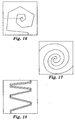
- Progressive designs include "progressive zig-zag” designs, comprising a "zig-zag” design where the spacing of adjacent channel segments is progressively closer toward one end of a flow field channel, such as depicted in Fig. 10 and schematically in Fig. 9 .
- a parallel-segment serpentine might also be made progressive, as depicted in Fig. 13 .
- Progressive spiral designs are also contemplated, such as depicted in Figs. 14-17 .
- the designs in Figs. 14-16 require an outlet that is not in plane with the flow field.
- design parameters for a given flow field design may also be determined by application of geometry and Darcy's Law, as demonstrated following for the case of a zig-zag flow field.
- a fuel cell stack may be designed for a preferential operating condition of operating current density and mass flow rates. In this case it is expedient to have the flow field optimized for those operating conditions. For a given flow field design and size, the pressure drop between the inlet and outlet will vary with total mass flow rate. At the preferred operating conditions, the flow rate will be fixed so the overall pressure drop will be fixed for the flow field.
- Figure 2 defines the geometry and parameters of a single zig-zag flow field according to the present invention.
- the apex half-angle, number and size of loops and the DCC permeabilities can be varied to optimize the tradeoff between pressure drop and uniformity and magnitude of the gas velocities flowing over the lands.
- the expression developed here gives a first order guideline to selection of those parameters. The expression can then be adapted to allow treatment of the case in which there is gas consumption.
- Figure 2 defines the geometry and parameters of the zig-zag flow field.
- a single loop has a minimum channel spacing on the end of width, w, and a maximum spacing on the other end of with, H.
- the length of the channel leg between the loop ends is L.
- Gas flows primarily in the channel, but also flows over the land, through the DCC, which has in-plane permeability, K L .
- the coordinate x specifies the point at which we want to derive an expression for the velocity in the y-direction, U y ( x ), across the land at point x .
- the gradient of pressure over the land at any value of x 0 is thus determined by the pressure drop along the loop channel between coordinates (x 0 , -y 0 /2) and (x 0 , y 0 /2), divided by the distance, y 0 .
- Equation (3) can be used to calculate the velocity as a function of position x, for different values of the parameter, ⁇ .
- the pressure is in units of Pascal, viscosity in kg/m ⁇ sec, permeability in units of m 2 , all dimensions in meters, and the velocity in m/sec.
- the pressure drop from inlet to outlet is about 5 psig, or 34,500 Pa.
- N can be fixed and the area A (or the rectangular length) of the electrode can be allowed to change, or the number of loops can change with ⁇ and the area A can be fixed.
- the magnitude of the flows e.g.
- the magnitude of the gas speed through the DCC can be controlled by its permeability, K , as shown by equation (3).
- Gas speed increases with higher DCC permeability.
- the rate at which the flow speed becomes uniform (within a certain %) with increasing ⁇ depends on the flow field parameters w and L , since they enter into the coefficients and sums of the cosine and tangent terms in (3).
- the overall geometry of the flow field would also seem to be important. E.g. if it were not square, but had an aspect ratio of 4, meaning it was 4 times longer than it was wide, how the flow channels zig-zagged over the area would be important. If the area was covered by fewer but longer loops running nearly parallel to the long direction, the pressure drop per loop would be larger than if there were more, shorter loops oriented orthogonally.
- a "progressive zig-zag" flow field according to the present invention can be designed to partially compensate for the loss of oxygen partial pressure due to consumption by progressively narrowing the apex angle closer to the flow field outlet.
- M w is the molecular weight of oxygen
- R the gas constant
- This invention is useful in constructing electrochemical cells such as fuel cells.
- the gas densities and viscosities used modeled those encountered on the air (cathode) side of a fuel cell, where an air flow provides oxygen to the cell. Similar models for the anode side could be constructed using gas densities and viscosities for a hydrogen fuel flow. The assumptions used in these models were steady-state laminar flow with constant viscosity (2.1 x 10 -5 kg/m ⁇ s) and temperature (75°C); no reactions or gas consumption were included except oxygen consumption as noted. Models that include oxygen consumption assume a constant and uniform oxygen consumption rate over the target area. The gas was considered ideal, implying that the density changes directly with the pressure.
- the porous medium of the fluid transport layer was modeled using Darcy's Law, for which the pressure drop has first order dependence on the viscosity, permeability, and flow velocity.
- air flow into the flow field inlet was 800 sccm and exit pressure was 253,000 Pascals (2.5 atmospheres).
- a CFD model was built for a comparative flow field, having a single serpentine channel composed of parallel adjacent segments, for a 50 cm 2 active area fuel cell, consisting of 25 parallel segments (making 24 loops) each 0.8 mm wide and 1.0 mm deep and spaced 2.0 mm apart (the land width).
- the CFD model calculations were done for the case of 800 sccm air flow, and no oxygen consumption.
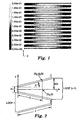
- Fig. 1 depicts the comparative flow field and shows, in the indicated gray scale, calculated gas velocities flowing over the lands in the Y direction within the DCC. Velocities are distributed along a spectrum from the lightest areas, representing velocities greater than 0.2 m/sec, to the dark areas, representing velocities less than 1/4 th that of the lightest area. From one side of each loop of the flow field channel to the other, there is considerable nonuniformity in the gas velocity over the land area.
- the total air mass flow rate was 800 sccm.
- Fig. 3 depicts the flow field and shows calculated gas velocities flowing in the Y direction over the lands within the DCC in the same gray scale as Fig. 1 .
- the velocities are approximately 0.13 m/sec. Some higher velocities are seen near the inlet and outlet holes. This represents a large improvement in uniformity over comparative Example 1C.
- Fig. 4 is a graph of inlet-to-outlet pressure drop as a function of mass flow rate for the comparative Example 2 and comparative Example 1 flow fields. It is seen that they have the same pressure drop, and therefore pressure drop was not disrupted by the change from a parallel-segment serpentine to a zig-zag serpentine design.
- Comparative Examples 3 and 4 were similar to comparative Example 2 except that apex half-angles ⁇ were changed to lower and higher values, 0.89 and 2.10 degrees respectively.
- the separation between sequential segments of the serpentine channels at the widest part (H) was 2.6 mm, 3.6 mm and 5.6 mm respectively for comparative Examples 3, 2 and 4. Due to the change in apex half-angle, the flow field of comparative Example 3 hard 31 segments (30 loops) and the flow field of comparative Example 4 had 19 segments (18 loops), and therefore the total channel length and pressure drop were larger for comparative Example 3 and less for comparative Example 4. It also follows that land area was less for comparative Example 3 and greater for comparative Example 4. Fig.
- FIG. 5 is a graph of gas velocity in the Y direction across a typical land feature as a function of lateral position along the land feature (i.e., in the X direction as depicted in Figs. 1 and 3 ), for each of comparative Examples 2-4 and comparative Example 1. Gas velocities in each of comparative Examples 2-4 are more uniform than in comparative Example 1, although comparative Example 2 appears to be more optimal than comparative Examples 3 and 4.
- the plots in Fig. 5 also show that the magnitude of the average velocities is reduced as the apex half-angle increases. As shown in more detail above, this effect can be offset by changing the value of the permeability, K, of the DCC.
- Example 5C the CFD model for the comparative flow field of comparative Example 1C, having a single serpentine channel composed of parallel adjacent channels, was run with the modification that oxygen consumption was added to the model at a stoichiometric flow ratio, ⁇ , of 2.0.
- the stoichiometric flow ratio is the ratio of oxygen supplied to oxygen consumed.
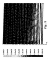
- Fig. 7 depicts the resulting in-plane oxygen flux, which is predominantly in the Y direction.
- Figs. 7 and 8 demonstrate that non-uniformities are amplified when oxygen consumption is initiated.
- the "zig-zag" serpentine is far superior in uniformity.
- a CFD model was built for a flow field similar to Example 6, including oxygen consumption at a stoichiometric flow ratio ( ⁇ ) of 2.0, but differing in that the apex half-angle, ⁇ , as defined in Fig. 9 , is progressively narrowed from 1.75 degrees at the inlet to 0.80 degrees at the outlet.
- the small end of the lands is fixed at 0.4mm while the large end varies from 4.8 mm to 2.4 mm. Note that the average large end is 3.6 mm, matching Example 2, and the number of channel segments is 25 as well, also matching Example 2.
- This "progressive zig-zig" flow field also comprised channel segments each 0.8 mm wide x 1.0 mm deep, forming an active area of 50 cm 2 and the overall channel length and land area were approximately the same as in Example 2.
- Figs. 10 and 11 demonstrate the in-plane oxygen flux in the Y direction and the gas velocities in the Y direction for this progressive zig-zag flow field.
- the progressively narrowing apex angle causes overland gas velocity on the downstream side of the flow field to increase, thereby compensating for the progressively decreasing partial pressure of oxygen caused by consumption.
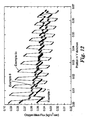
- Fig. 12 compares the flow fields of Examples 5C, 6 and 7. It is evident that the zig-zag serpentine flow field according to the present invention demonstrates far more uniform oxygen flux than the comparative parallel-segment serpentine, and the progressive zig-zag demonstrates even better uniformity.
Landscapes
- Life Sciences & Earth Sciences (AREA)
- Engineering & Computer Science (AREA)
- Manufacturing & Machinery (AREA)
- Sustainable Development (AREA)
- Sustainable Energy (AREA)
- Chemical & Material Sciences (AREA)
- Chemical Kinetics & Catalysis (AREA)
- Electrochemistry (AREA)
- General Chemical & Material Sciences (AREA)
- Fuel Cell (AREA)
- Crystals, And After-Treatments Of Crystals (AREA)
- Inert Electrodes (AREA)
- Physical Or Chemical Processes And Apparatus (AREA)
Applications Claiming Priority (3)
| Application Number | Priority Date | Filing Date | Title |
|---|---|---|---|
| US09/954,601 US6780536B2 (en) | 2001-09-17 | 2001-09-17 | Flow field |
| US954601 | 2001-09-17 | ||
| PCT/US2002/025424 WO2003026053A1 (en) | 2001-09-17 | 2002-08-12 | Flow field |
Publications (2)
| Publication Number | Publication Date |
|---|---|
| EP1428279A1 EP1428279A1 (en) | 2004-06-16 |
| EP1428279B1 true EP1428279B1 (en) | 2008-05-14 |
Family
ID=25495671
Family Applications (1)
| Application Number | Title | Priority Date | Filing Date |
|---|---|---|---|
| EP02761318A Expired - Lifetime EP1428279B1 (en) | 2001-09-17 | 2002-08-12 | Flow field |
Country Status (8)
| Country | Link |
|---|---|
| US (1) | US6780536B2 (https=) |
| EP (1) | EP1428279B1 (https=) |
| JP (1) | JP4874519B2 (https=) |
| KR (1) | KR20040033053A (https=) |
| AT (1) | ATE395721T1 (https=) |
| CA (1) | CA2460563A1 (https=) |
| DE (1) | DE60226624D1 (https=) |
| WO (1) | WO2003026053A1 (https=) |
Families Citing this family (45)
| Publication number | Priority date | Publication date | Assignee | Title |
|---|---|---|---|---|
| DE10204598A1 (de) * | 2002-02-05 | 2003-08-07 | Volkswagen Ag | Verfahren zur Verbesserung eines Wärme- und Stofftransports in einer Diffusionsschicht einer Brennstoffzelle und entsprechende Brennstoffzelle |
| US6890680B2 (en) * | 2002-02-19 | 2005-05-10 | Mti Microfuel Cells Inc. | Modified diffusion layer for use in a fuel cell system |
| US7482088B2 (en) * | 2003-01-31 | 2009-01-27 | 3M Innovative Properties Company | Flow field |
| JP3956864B2 (ja) * | 2003-02-13 | 2007-08-08 | トヨタ自動車株式会社 | 流路構造を有する燃料電池のセパレータ |
| US20040265675A1 (en) * | 2003-06-24 | 2004-12-30 | General Electric Company | Fuel Cell Flow Field Design |
| FR2858466A1 (fr) * | 2003-07-28 | 2005-02-04 | Renault Sa | Plaque bipolaire pour pile a combustible |
| WO2005024985A2 (de) * | 2003-08-29 | 2005-03-17 | Zentrum für Sonnenenergie- und Wasserstoff-Forschung Baden-Württemberg Gemeinnützige Stiftung | Gasverteilerfeld für eine brennstoffzelle und ein solches enthaltende brennstoffzelle |
| US7297428B2 (en) * | 2003-10-31 | 2007-11-20 | 3M Innovative Properties Company | Registration arrangement for fuel cell assemblies |
| US20050095485A1 (en) * | 2003-10-31 | 2005-05-05 | 3M Innovative Properties Company | Fuel cell end plate assembly |
| US20050130017A1 (en) * | 2003-12-15 | 2005-06-16 | Zhiqiang Xu | Fuel cell plate |
| US20050136317A1 (en) * | 2003-12-19 | 2005-06-23 | 3M Innovative Properties Company | Molded multi-part flow field structure |
| FR2869464B1 (fr) * | 2004-04-21 | 2006-05-26 | Renault Sas | Plaque bipolaire pour pile a combustible |
| US7531264B2 (en) * | 2004-06-07 | 2009-05-12 | Hyteon Inc. | Fuel cell stack with even distributing gas manifolds |
| US7524575B2 (en) * | 2004-06-07 | 2009-04-28 | Hyteon Inc. | Flow field plate for use in fuel cells |
| US20060008695A1 (en) * | 2004-07-09 | 2006-01-12 | Dingrong Bai | Fuel cell with in-cell humidification |
| US7314680B2 (en) * | 2004-09-24 | 2008-01-01 | Hyteon Inc | Integrated fuel cell power module |
| KR100626034B1 (ko) * | 2004-11-13 | 2006-09-20 | 삼성에스디아이 주식회사 | 바이폴라 플레이트 및 직접액체연료전지 스택 |
| FR2879353B1 (fr) * | 2004-12-10 | 2013-08-02 | Renault Sas | Plaque bipolaire comportant un sillon qui s'etend selon une double spirale et qui comporte un segment retiligne agence dans la zone centrale de la spirale |
| US7479333B2 (en) * | 2004-12-13 | 2009-01-20 | Hyteon, Inc. | Fuel cell stack with multiple groups of cells and flow passes |
| US7041408B1 (en) * | 2004-12-28 | 2006-05-09 | Utc Fuel Cells, Llc | Varied fuel cell oxidant flow channel depth resulting in fewer cooler plates |
| US7311990B2 (en) * | 2004-12-29 | 2007-12-25 | 3M Innovative Properties Company | Form-in-place fastening for fuel cell assemblies |
| US20060141138A1 (en) * | 2004-12-29 | 2006-06-29 | 3M Innovative Properties Company | Microwave annealing of membranes for use in fuel cell assemblies |
| US7339635B2 (en) * | 2005-01-14 | 2008-03-04 | 3M Innovative Properties Company | Pre-stacked optical films with adhesive layer |
| US20060188763A1 (en) * | 2005-02-22 | 2006-08-24 | Dingrong Bai | Fuel cell system comprising modular design features |
| CN100527501C (zh) * | 2005-10-20 | 2009-08-12 | 中国科学院电工研究所 | 一种用于燃料电池的流场板 |
| EP1970985A1 (de) * | 2007-03-08 | 2008-09-17 | Siemens Aktiengesellschaft | Brennstoffzelle |
| JP5018150B2 (ja) * | 2007-03-12 | 2012-09-05 | ソニー株式会社 | 燃料電池、電子機器、燃料供給板および燃料供給方法 |
| WO2008126358A1 (ja) * | 2007-03-15 | 2008-10-23 | Panasonic Corporation | 高分子電解質形燃料電池及びそれを備える燃料電池スタック |
| DE102008033211A1 (de) | 2008-07-15 | 2010-01-21 | Daimler Ag | Bipolarplatte für eine Brennstoffzellenanordnung, insbesondere zur Anordnung zwischen zwei benachbarten Membran-Elektroden-Anordnungen |
| DE102008033209A1 (de) | 2008-07-15 | 2010-01-21 | Daimler Ag | Brennstoffzellenanordnung |
| US8177884B2 (en) | 2009-05-20 | 2012-05-15 | United Technologies Corporation | Fuel deoxygenator with porous support plate |
| JP2012142135A (ja) * | 2010-12-28 | 2012-07-26 | Toyota Motor Corp | 燃料電池 |
| GB2519493A (en) | 2012-08-14 | 2015-04-22 | Powerdisc Dev Corp Ltd | Fuel cells components, stacks and modular fuel cell systems |
| US9644277B2 (en) | 2012-08-14 | 2017-05-09 | Loop Energy Inc. | Reactant flow channels for electrolyzer applications |
| CA2919875C (en) | 2012-08-14 | 2021-08-17 | Powerdisc Development Corporation Ltd. | Fuel cell flow channels and flow fields |
| DE102012109080B3 (de) | 2012-09-26 | 2013-12-24 | Zentrum für Sonnenenergie- und Wasserstoff-Forschung Baden-Württemberg Gemeinnützige Stiftung | Medienverteilerfeldplatte mit erhöhter, homogener Stromdichteverteilung für eine elektrochemische Zelle und eine solche enthaltende elektrochemische Zelle |
| EP2907185B1 (en) * | 2012-10-09 | 2017-01-18 | Nuvera Fuel Cells, LLC | Design of bipolar plates for use in conduction-cooled electrochemical cells |
| WO2014063908A1 (en) * | 2012-10-23 | 2014-05-01 | Metacon Ab | Disc shaped fuel cell |
| US10180289B2 (en) | 2014-01-30 | 2019-01-15 | Dana Canada Corporation | Flow balanced heat exchanger for battery thermal management |
| CN104852068B (zh) * | 2015-05-26 | 2017-08-01 | 苏州弗尔赛能源科技股份有限公司 | 一种质子交换膜燃料电池双极板分配头及其设计方法 |
| CA2987962A1 (en) | 2015-06-04 | 2016-12-08 | Dana Canada Corporation | Heat exchanger with regional flow distribution for uniform cooling of battery cells |
| EP3433894B1 (en) | 2016-03-22 | 2024-05-08 | Loop Energy Inc. | Fuel cell flow field design for thermal management |
| JP7052418B2 (ja) * | 2018-03-01 | 2022-04-12 | トヨタ自動車株式会社 | ガス拡散層 |
| US12586798B2 (en) | 2021-07-03 | 2026-03-24 | Cevizdere LLC | Methods and apparatus for mold mitigation in fuel cell humidifiers |
| CN113675424B (zh) * | 2021-07-27 | 2023-03-31 | 华南理工大学 | 一种基于正弦波纹的衍生型波纹流场板 |
Family Cites Families (68)
| Publication number | Priority date | Publication date | Assignee | Title |
|---|---|---|---|---|
| US4324844A (en) * | 1980-04-28 | 1982-04-13 | Westinghouse Electric Corp. | Variable area fuel cell cooling |
| US4292379A (en) * | 1980-04-28 | 1981-09-29 | Westinghouse Electric Corp. | Variable area fuel cell process channels |
| JPS60189868A (ja) * | 1984-03-12 | 1985-09-27 | Fuji Electric Corp Res & Dev Ltd | 燃料電池 |
| JPH081805B2 (ja) * | 1985-06-14 | 1996-01-10 | 株式会社日立製作所 | 燃料電池 |
| JPS6240168A (ja) * | 1985-08-13 | 1987-02-21 | Mitsubishi Electric Corp | 積層形燃料電池 |
| US4631239A (en) * | 1985-12-04 | 1986-12-23 | Westinghouse Electric Corp. | Fuel cell plates with improved arrangement of process channels for enhanced pressure drop across the plates |
| US4853301A (en) * | 1985-12-04 | 1989-08-01 | The United States Of America As Represented By The United States Department Of Energy | Fuel cell plates with skewed process channels for uniform distribution of stack compression load |
| US4855193A (en) * | 1986-06-20 | 1989-08-08 | United Technologies Corporation | Bipolar fuel cell |
| US5108849A (en) * | 1989-08-30 | 1992-04-28 | Her Majesty The Queen In Right Of Canada, As Represented By The Minister Of National Defence In Her Britannic Majesty's Government Of The United Kingdom Of Great Britain And Northern Ireland | Fuel cell fluid flow field plate |
| US4988583A (en) * | 1989-08-30 | 1991-01-29 | Her Majesty The Queen As Represented By The Minister Of National Defence Of Her Majesty's Canadian Government | Novel fuel cell fluid flow field plate |
| JPH0463562A (ja) * | 1990-07-03 | 1992-02-28 | Terumo Corp | 食品用材料の製造方法 |
| DE4128515C1 (https=) | 1991-08-28 | 1992-11-12 | Abb Patent Gmbh, 6800 Mannheim, De | |
| US5252410A (en) * | 1991-09-13 | 1993-10-12 | Ballard Power Systems Inc. | Lightweight fuel cell membrane electrode assembly with integral reactant flow passages |
| US5300370A (en) | 1992-11-13 | 1994-04-05 | Ballard Power Systems Inc. | Laminated fluid flow field assembly for electrochemical fuel cells |
| US5773160A (en) * | 1994-06-24 | 1998-06-30 | Ballard Power Systems Inc. | Electrochemical fuel cell stack with concurrent flow of coolant and oxidant streams and countercurrent flow of fuel and oxidant streams |
| RU2174728C2 (ru) * | 1994-10-12 | 2001-10-10 | Х Пауэр Корпорейшн | Топливный элемент, использующий интегральную технологию пластин для распределения жидкости |
| DE4443939C1 (de) * | 1994-12-09 | 1996-08-29 | Fraunhofer Ges Forschung | PEM-Brennstoffzelle mit strukturierten Platten |
| US5514487A (en) * | 1994-12-27 | 1996-05-07 | Ballard Power Systems Inc. | Edge manifold assembly for an electrochemical fuel cell stack |
| US5879826A (en) * | 1995-07-05 | 1999-03-09 | Humboldt State University Foundation | Proton exchange membrane fuel cell |
| US5840438A (en) * | 1995-08-25 | 1998-11-24 | Ballard Power Systems Inc. | Electrochemical fuel cell with an electrode substrate having an in-plane nonuniform structure for control of reactant and product transport |
| US5641586A (en) * | 1995-12-06 | 1997-06-24 | The Regents Of The University Of California Office Of Technology Transfer | Fuel cell with interdigitated porous flow-field |
| JP3540491B2 (ja) * | 1996-03-07 | 2004-07-07 | 政廣 渡辺 | 燃料電池及び電解セル並びにその冷却・除湿方法 |
| US5686199A (en) * | 1996-05-07 | 1997-11-11 | Alliedsignal Inc. | Flow field plate for use in a proton exchange membrane fuel cell |
| JP3713912B2 (ja) * | 1996-08-08 | 2005-11-09 | アイシン精機株式会社 | 燃料電池のガス通路板 |
| US5798187A (en) * | 1996-09-27 | 1998-08-25 | The Regents Of The University Of California | Fuel cell with metal screen flow-field |
| US5773161A (en) * | 1996-10-02 | 1998-06-30 | Energy Research Corporation | Bipolar separator |
| JPH10125338A (ja) * | 1996-10-22 | 1998-05-15 | Fuji Electric Co Ltd | 固体高分子電解質型燃料電池 |
| US5804326A (en) * | 1996-12-20 | 1998-09-08 | Ballard Power Systems Inc. | Integrated reactant and coolant fluid flow field layer for an electrochemical fuel cell |
| US5858569A (en) * | 1997-03-21 | 1999-01-12 | Plug Power L.L.C. | Low cost fuel cell stack design |
| JPH10284096A (ja) | 1997-04-01 | 1998-10-23 | Fuji Electric Co Ltd | 固体高分子電解質型燃料電池 |
| US5885728A (en) * | 1997-04-04 | 1999-03-23 | Ucar Carbon Technology Corporation | Flexible graphite composite |
| US5942347A (en) * | 1997-05-20 | 1999-08-24 | Institute Of Gas Technology | Proton exchange membrane fuel cell separator plate |
| US6048634A (en) * | 1997-06-18 | 2000-04-11 | H Power Corporation | Fuel cell using water-soluble fuel |
| US5776625A (en) * | 1997-06-18 | 1998-07-07 | H Power Corporation | Hydrogen-air fuel cell |
| JP3272980B2 (ja) * | 1997-06-26 | 2002-04-08 | 松下電器産業株式会社 | 燃料電池 |
| US5906898A (en) * | 1997-09-18 | 1999-05-25 | M-C Power Corporation | Finned internal manifold oxidant cooled fuel cell stack system |
| US6099984A (en) * | 1997-12-15 | 2000-08-08 | General Motors Corporation | Mirrored serpentine flow channels for fuel cell |
| JPH11283639A (ja) * | 1998-03-27 | 1999-10-15 | Toyota Motor Corp | 燃料電池用セパレータおよび燃料電池 |
| JP4205774B2 (ja) * | 1998-03-02 | 2009-01-07 | 本田技研工業株式会社 | 燃料電池 |
| US6071635A (en) * | 1998-04-03 | 2000-06-06 | Plug Power, L.L.C. | Easily-formable fuel cell assembly fluid flow plate having conductivity and increased non-conductive material |
| US5945232A (en) * | 1998-04-03 | 1999-08-31 | Plug Power, L.L.C. | PEM-type fuel cell assembly having multiple parallel fuel cell sub-stacks employing shared fluid plate assemblies and shared membrane electrode assemblies |
| JP2000003715A (ja) | 1998-04-15 | 2000-01-07 | Fuji Electric Corp Res & Dev Ltd | 固体電解質型燃料電池 |
| GB9808524D0 (en) | 1998-04-23 | 1998-06-17 | British Gas Plc | Fuel cell flow-field structure formed by layer deposition |
| US6007933A (en) * | 1998-04-27 | 1999-12-28 | Plug Power, L.L.C. | Fuel cell assembly unit for promoting fluid service and electrical conductivity |
| CA2241566A1 (en) | 1998-06-23 | 1999-12-23 | Bondface Technology Inc. | Flow field plate |
| GB9814121D0 (en) | 1998-07-01 | 1998-08-26 | British Gas Plc | Separator plate for the use in a fuel cell stack |
| JP2000077083A (ja) | 1998-08-31 | 2000-03-14 | Isuzu Motors Ltd | 燃料電池 |
| DE19840517A1 (de) * | 1998-09-04 | 2000-03-16 | Manhattan Scientifics Inc | Gasdiffusionsstruktur senkrecht zur Membran von Polymerelektrolyt-Membran Brennstoffzellen |
| US6207312B1 (en) * | 1998-09-18 | 2001-03-27 | Energy Partners, L.C. | Self-humidifying fuel cell |
| JP4245091B2 (ja) * | 1998-10-01 | 2009-03-25 | 本田技研工業株式会社 | 燃料電池 |
| US6174616B1 (en) * | 1998-10-07 | 2001-01-16 | Plug Power Inc. | Fuel cell assembly unit for promoting fluid service and design flexibility |
| US6093502A (en) * | 1998-10-28 | 2000-07-25 | Plug Power Inc. | Fuel cell with selective pressure variation and dynamic inflection |
| AU1600800A (en) * | 1998-10-29 | 2000-05-22 | 3M Innovative Properties Company | Microstructured flow fields |
| JP2000195530A (ja) | 1998-12-24 | 2000-07-14 | Aisin Takaoka Ltd | 燃料電池及びセパレータ |
| AU4175000A (en) | 1999-03-25 | 2000-10-09 | George A. Marchetti | Thin graphite bipolar plate with associated gaskets and carbon cloth flow-field for use in a fuel cell |
| US6569554B1 (en) | 1999-07-28 | 2003-05-27 | Sulzer Hexis Ag | Fuel cell battery with a stack of planar cells |
| JP2001057219A (ja) | 1999-08-19 | 2001-02-27 | Mitsubishi Electric Corp | 燃料電池 |
| JP2001076747A (ja) | 1999-08-31 | 2001-03-23 | Micro:Kk | 固体高分子型燃料電池 |
| US6150049A (en) * | 1999-09-17 | 2000-11-21 | Plug Power Inc. | Fluid flow plate for distribution of hydration fluid in a fuel cell |
| US6309773B1 (en) | 1999-12-13 | 2001-10-30 | General Motors Corporation | Serially-linked serpentine flow channels for PEM fuel cell |
| US6586128B1 (en) * | 2000-05-09 | 2003-07-01 | Ballard Power Systems, Inc. | Differential pressure fluid flow fields for fuel cells |
| CA2352443C (en) * | 2000-07-07 | 2005-12-27 | Nippon Steel Corporation | Separators for solid polymer fuel cells and method for producing same, and solid polymer fuel cells |
| US6551736B1 (en) * | 2000-10-30 | 2003-04-22 | Teledyne Energy Systems, Inc. | Fuel cell collector plates with improved mass transfer channels |
| US6544681B2 (en) * | 2000-12-26 | 2003-04-08 | Ballard Power Systems, Inc. | Corrugated flow field plate assembly for a fuel cell |
| DE10100757A1 (de) | 2001-01-10 | 2002-08-01 | Daimler Chrysler Ag | Elektrochemischer Brennstoffzellenstapel |
| US6503653B2 (en) * | 2001-02-23 | 2003-01-07 | General Motors Corporation | Stamped bipolar plate for PEM fuel cell stack |
| US6607857B2 (en) * | 2001-05-31 | 2003-08-19 | General Motors Corporation | Fuel cell separator plate having controlled fiber orientation and method of manufacture |
| US6686084B2 (en) * | 2002-01-04 | 2004-02-03 | Hybrid Power Generation Systems, Llc | Gas block mechanism for water removal in fuel cells |
-
2001
- 2001-09-17 US US09/954,601 patent/US6780536B2/en not_active Expired - Lifetime
-
2002
- 2002-08-12 KR KR10-2004-7003855A patent/KR20040033053A/ko not_active Ceased
- 2002-08-12 DE DE60226624T patent/DE60226624D1/de not_active Expired - Lifetime
- 2002-08-12 CA CA002460563A patent/CA2460563A1/en not_active Abandoned
- 2002-08-12 JP JP2003529563A patent/JP4874519B2/ja not_active Expired - Fee Related
- 2002-08-12 AT AT02761318T patent/ATE395721T1/de not_active IP Right Cessation
- 2002-08-12 EP EP02761318A patent/EP1428279B1/en not_active Expired - Lifetime
- 2002-08-12 WO PCT/US2002/025424 patent/WO2003026053A1/en not_active Ceased
Also Published As
| Publication number | Publication date |
|---|---|
| JP4874519B2 (ja) | 2012-02-15 |
| US20030059662A1 (en) | 2003-03-27 |
| WO2003026053A1 (en) | 2003-03-27 |
| US6780536B2 (en) | 2004-08-24 |
| EP1428279A1 (en) | 2004-06-16 |
| ATE395721T1 (de) | 2008-05-15 |
| DE60226624D1 (de) | 2008-06-26 |
| CA2460563A1 (en) | 2003-03-27 |
| KR20040033053A (ko) | 2004-04-17 |
| JP2005503654A (ja) | 2005-02-03 |
Similar Documents
| Publication | Publication Date | Title |
|---|---|---|
| EP1428279B1 (en) | Flow field | |
| US7838139B2 (en) | Flow field plate geometries | |
| US6555261B1 (en) | Microstructured flow fields | |
| US7067213B2 (en) | Flow field plate geometries | |
| US6586128B1 (en) | Differential pressure fluid flow fields for fuel cells | |
| CA2471122C (en) | Fuel cell fluid flow field plates | |
| US8304145B2 (en) | High tortuosity diffusion medium | |
| JP2006527906A (ja) | フローフィールドプレートジオメトリ | |
| WO1997042672A1 (en) | Flow field plate for use in a proton exchange membrane fuel cell | |
| WO2004114446A1 (en) | Flow field plate geometries | |
| CA2953419A1 (en) | Flow fields for use with and electrochemical cell | |
| WO2023044562A1 (en) | Flow fields for electrolyzers with liquid water supplied to the cathode | |
| US20240120510A1 (en) | Gas diffusion layer, separator and electrochemical reactor | |
| CN117973048A (zh) | Pem电解槽组合式流场结构设计方法 | |
| US20070009779A1 (en) | Fuel cell | |
| CN111971831B (zh) | 电化学电池堆的阴极流场分布 | |
| EP1839360A1 (en) | Improved fuel cell cathode flow field | |
| Ma et al. | Effects of partially narrowed flow channel on performance of polymer electrolyte fuel cell | |
| Li | Bipolar plates and flow field design | |
| US20110014538A1 (en) | Fuel cell | |
| Barbir | Fuel cell stack design principles with some design concepts of micro-mini fuel cells | |
| EP4648145A1 (en) | Flow channel plate and electrochemical cell | |
| Debe et al. | Design and development of a novel flow field for Pem fuel cells to obtain uniform flow distribution | |
| GB2403061A (en) | Flow field plate geometries | |
| US20110014537A1 (en) | Fuel cell |
Legal Events
| Date | Code | Title | Description |
|---|---|---|---|
| PUAI | Public reference made under article 153(3) epc to a published international application that has entered the european phase |
Free format text: ORIGINAL CODE: 0009012 |
|
| 17P | Request for examination filed |
Effective date: 20040408 |
|
| AK | Designated contracting states |
Kind code of ref document: A1 Designated state(s): AT BE BG CH CY CZ DE DK EE ES FI FR GB GR IE IT LI LU MC NL PT SE SK TR |
|
| AX | Request for extension of the european patent |
Extension state: AL LT LV MK RO SI |
|
| 17Q | First examination report despatched |
Effective date: 20040722 |
|
| GRAP | Despatch of communication of intention to grant a patent |
Free format text: ORIGINAL CODE: EPIDOSNIGR1 |
|
| GRAS | Grant fee paid |
Free format text: ORIGINAL CODE: EPIDOSNIGR3 |
|
| GRAA | (expected) grant |
Free format text: ORIGINAL CODE: 0009210 |
|
| AK | Designated contracting states |
Kind code of ref document: B1 Designated state(s): AT BE BG CH CY CZ DE DK EE ES FI FR GB GR IE IT LI LU MC NL PT SE SK TR |
|
| REG | Reference to a national code |
Ref country code: GB Ref legal event code: FG4D |
|
| REG | Reference to a national code |
Ref country code: CH Ref legal event code: EP |
|
| REG | Reference to a national code |
Ref country code: IE Ref legal event code: FG4D Free format text: LANGUAGE OF EP DOCUMENT: FRENCH |
|
| REF | Corresponds to: |
Ref document number: 60226624 Country of ref document: DE Date of ref document: 20080626 Kind code of ref document: P |
|
| PG25 | Lapsed in a contracting state [announced via postgrant information from national office to epo] |
Ref country code: FI Free format text: LAPSE BECAUSE OF FAILURE TO SUBMIT A TRANSLATION OF THE DESCRIPTION OR TO PAY THE FEE WITHIN THE PRESCRIBED TIME-LIMIT Effective date: 20080514 Ref country code: ES Free format text: LAPSE BECAUSE OF FAILURE TO SUBMIT A TRANSLATION OF THE DESCRIPTION OR TO PAY THE FEE WITHIN THE PRESCRIBED TIME-LIMIT Effective date: 20080825 |
|
| NLV1 | Nl: lapsed or annulled due to failure to fulfill the requirements of art. 29p and 29m of the patents act | ||
| PG25 | Lapsed in a contracting state [announced via postgrant information from national office to epo] |
Ref country code: NL Free format text: LAPSE BECAUSE OF FAILURE TO SUBMIT A TRANSLATION OF THE DESCRIPTION OR TO PAY THE FEE WITHIN THE PRESCRIBED TIME-LIMIT Effective date: 20080514 Ref country code: AT Free format text: LAPSE BECAUSE OF FAILURE TO SUBMIT A TRANSLATION OF THE DESCRIPTION OR TO PAY THE FEE WITHIN THE PRESCRIBED TIME-LIMIT Effective date: 20080514 |
|
| PG25 | Lapsed in a contracting state [announced via postgrant information from national office to epo] |
Ref country code: CZ Free format text: LAPSE BECAUSE OF FAILURE TO SUBMIT A TRANSLATION OF THE DESCRIPTION OR TO PAY THE FEE WITHIN THE PRESCRIBED TIME-LIMIT Effective date: 20080514 Ref country code: DK Free format text: LAPSE BECAUSE OF FAILURE TO SUBMIT A TRANSLATION OF THE DESCRIPTION OR TO PAY THE FEE WITHIN THE PRESCRIBED TIME-LIMIT Effective date: 20080514 Ref country code: SE Free format text: LAPSE BECAUSE OF FAILURE TO SUBMIT A TRANSLATION OF THE DESCRIPTION OR TO PAY THE FEE WITHIN THE PRESCRIBED TIME-LIMIT Effective date: 20080814 Ref country code: PT Free format text: LAPSE BECAUSE OF FAILURE TO SUBMIT A TRANSLATION OF THE DESCRIPTION OR TO PAY THE FEE WITHIN THE PRESCRIBED TIME-LIMIT Effective date: 20081014 |
|
| PG25 | Lapsed in a contracting state [announced via postgrant information from national office to epo] |
Ref country code: BE Free format text: LAPSE BECAUSE OF FAILURE TO SUBMIT A TRANSLATION OF THE DESCRIPTION OR TO PAY THE FEE WITHIN THE PRESCRIBED TIME-LIMIT Effective date: 20080514 Ref country code: SK Free format text: LAPSE BECAUSE OF FAILURE TO SUBMIT A TRANSLATION OF THE DESCRIPTION OR TO PAY THE FEE WITHIN THE PRESCRIBED TIME-LIMIT Effective date: 20080514 |
|
| PLBE | No opposition filed within time limit |
Free format text: ORIGINAL CODE: 0009261 |
|
| STAA | Information on the status of an ep patent application or granted ep patent |
Free format text: STATUS: NO OPPOSITION FILED WITHIN TIME LIMIT |
|
| PG25 | Lapsed in a contracting state [announced via postgrant information from national office to epo] |
Ref country code: MC Free format text: LAPSE BECAUSE OF NON-PAYMENT OF DUE FEES Effective date: 20080831 |
|
| REG | Reference to a national code |
Ref country code: CH Ref legal event code: PL |
|
| 26N | No opposition filed |
Effective date: 20090217 |
|
| GBPC | Gb: european patent ceased through non-payment of renewal fee |
Effective date: 20080814 |
|
| PG25 | Lapsed in a contracting state [announced via postgrant information from national office to epo] |
Ref country code: EE Free format text: LAPSE BECAUSE OF FAILURE TO SUBMIT A TRANSLATION OF THE DESCRIPTION OR TO PAY THE FEE WITHIN THE PRESCRIBED TIME-LIMIT Effective date: 20080514 Ref country code: BG Free format text: LAPSE BECAUSE OF FAILURE TO SUBMIT A TRANSLATION OF THE DESCRIPTION OR TO PAY THE FEE WITHIN THE PRESCRIBED TIME-LIMIT Effective date: 20080814 |
|
| PG25 | Lapsed in a contracting state [announced via postgrant information from national office to epo] |
Ref country code: LI Free format text: LAPSE BECAUSE OF NON-PAYMENT OF DUE FEES Effective date: 20080831 Ref country code: CH Free format text: LAPSE BECAUSE OF NON-PAYMENT OF DUE FEES Effective date: 20080831 |
|
| PG25 | Lapsed in a contracting state [announced via postgrant information from national office to epo] |
Ref country code: IE Free format text: LAPSE BECAUSE OF NON-PAYMENT OF DUE FEES Effective date: 20080812 |
|
| PG25 | Lapsed in a contracting state [announced via postgrant information from national office to epo] |
Ref country code: IT Free format text: LAPSE BECAUSE OF FAILURE TO SUBMIT A TRANSLATION OF THE DESCRIPTION OR TO PAY THE FEE WITHIN THE PRESCRIBED TIME-LIMIT Effective date: 20080514 |
|
| PG25 | Lapsed in a contracting state [announced via postgrant information from national office to epo] |
Ref country code: GB Free format text: LAPSE BECAUSE OF NON-PAYMENT OF DUE FEES Effective date: 20080814 |
|
| PG25 | Lapsed in a contracting state [announced via postgrant information from national office to epo] |
Ref country code: LU Free format text: LAPSE BECAUSE OF NON-PAYMENT OF DUE FEES Effective date: 20080812 Ref country code: CY Free format text: LAPSE BECAUSE OF FAILURE TO SUBMIT A TRANSLATION OF THE DESCRIPTION OR TO PAY THE FEE WITHIN THE PRESCRIBED TIME-LIMIT Effective date: 20080514 |
|
| PG25 | Lapsed in a contracting state [announced via postgrant information from national office to epo] |
Ref country code: TR Free format text: LAPSE BECAUSE OF FAILURE TO SUBMIT A TRANSLATION OF THE DESCRIPTION OR TO PAY THE FEE WITHIN THE PRESCRIBED TIME-LIMIT Effective date: 20080514 |
|
| PG25 | Lapsed in a contracting state [announced via postgrant information from national office to epo] |
Ref country code: GR Free format text: LAPSE BECAUSE OF FAILURE TO SUBMIT A TRANSLATION OF THE DESCRIPTION OR TO PAY THE FEE WITHIN THE PRESCRIBED TIME-LIMIT Effective date: 20080815 |
|
| REG | Reference to a national code |
Ref country code: FR Ref legal event code: ST Effective date: 20110708 |
|
| PG25 | Lapsed in a contracting state [announced via postgrant information from national office to epo] |
Ref country code: FR Free format text: LAPSE BECAUSE OF NON-PAYMENT OF DUE FEES Effective date: 20080901 |
|
| PGFP | Annual fee paid to national office [announced via postgrant information from national office to epo] |
Ref country code: DE Payment date: 20190730 Year of fee payment: 18 |
|
| REG | Reference to a national code |
Ref country code: DE Ref legal event code: R119 Ref document number: 60226624 Country of ref document: DE |
|
| PG25 | Lapsed in a contracting state [announced via postgrant information from national office to epo] |
Ref country code: DE Free format text: LAPSE BECAUSE OF NON-PAYMENT OF DUE FEES Effective date: 20210302 |